EP2682684A2 - Humidifier apparatus using a photocatalyst having an air-cleaning function - Google Patents
Humidifier apparatus using a photocatalyst having an air-cleaning function Download PDFInfo
- Publication number
- EP2682684A2 EP2682684A2 EP12752956.8A EP12752956A EP2682684A2 EP 2682684 A2 EP2682684 A2 EP 2682684A2 EP 12752956 A EP12752956 A EP 12752956A EP 2682684 A2 EP2682684 A2 EP 2682684A2
- Authority
- EP
- European Patent Office
- Prior art keywords
- photocatalyst
- housing
- filter
- air
- adsorption
- Prior art date
- Legal status (The legal status is an assumption and is not a legal conclusion. Google has not performed a legal analysis and makes no representation as to the accuracy of the status listed.)
- Granted
Links
- 239000011941 photocatalyst Substances 0.000 title claims abstract description 121
- 238000004140 cleaning Methods 0.000 title claims abstract description 64
- 238000001179 sorption measurement Methods 0.000 claims abstract description 83
- 239000011148 porous material Substances 0.000 claims abstract description 75
- XLYOFNOQVPJJNP-UHFFFAOYSA-N water Substances O XLYOFNOQVPJJNP-UHFFFAOYSA-N 0.000 claims abstract description 52
- 238000010521 absorption reaction Methods 0.000 claims abstract description 43
- 238000010926 purge Methods 0.000 claims description 7
- 238000005265 energy consumption Methods 0.000 abstract description 4
- 239000000356 contaminant Substances 0.000 description 22
- GWEVSGVZZGPLCZ-UHFFFAOYSA-N Titan oxide Chemical compound O=[Ti]=O GWEVSGVZZGPLCZ-UHFFFAOYSA-N 0.000 description 9
- 230000000052 comparative effect Effects 0.000 description 8
- 150000001450 anions Chemical class 0.000 description 7
- 239000003463 adsorbent Substances 0.000 description 5
- 238000006243 chemical reaction Methods 0.000 description 5
- 239000000428 dust Substances 0.000 description 4
- CBENFWSGALASAD-UHFFFAOYSA-N Ozone Chemical compound [O-][O+]=O CBENFWSGALASAD-UHFFFAOYSA-N 0.000 description 3
- 230000009471 action Effects 0.000 description 3
- 230000000844 anti-bacterial effect Effects 0.000 description 3
- 230000003373 anti-fouling effect Effects 0.000 description 3
- 239000003054 catalyst Substances 0.000 description 3
- 230000009467 reduction Effects 0.000 description 3
- 239000004408 titanium dioxide Substances 0.000 description 3
- 239000003440 toxic substance Substances 0.000 description 3
- 239000012855 volatile organic compound Substances 0.000 description 3
- OKTJSMMVPCPJKN-UHFFFAOYSA-N Carbon Chemical compound [C] OKTJSMMVPCPJKN-UHFFFAOYSA-N 0.000 description 2
- VYPSYNLAJGMNEJ-UHFFFAOYSA-N Silicium dioxide Chemical compound O=[Si]=O VYPSYNLAJGMNEJ-UHFFFAOYSA-N 0.000 description 2
- 238000010586 diagram Methods 0.000 description 2
- 230000000694 effects Effects 0.000 description 2
- 238000001704 evaporation Methods 0.000 description 2
- 238000009434 installation Methods 0.000 description 2
- 230000003647 oxidation Effects 0.000 description 2
- 238000007254 oxidation reaction Methods 0.000 description 2
- 238000006552 photochemical reaction Methods 0.000 description 2
- 231100000614 poison Toxicity 0.000 description 2
- 238000000746 purification Methods 0.000 description 2
- 241000894006 Bacteria Species 0.000 description 1
- 229920002472 Starch Polymers 0.000 description 1
- 229910021536 Zeolite Inorganic materials 0.000 description 1
- 230000004913 activation Effects 0.000 description 1
- 230000004075 alteration Effects 0.000 description 1
- PNEYBMLMFCGWSK-UHFFFAOYSA-N aluminium oxide Inorganic materials [O-2].[O-2].[O-2].[Al+3].[Al+3] PNEYBMLMFCGWSK-UHFFFAOYSA-N 0.000 description 1
- 230000008901 benefit Effects 0.000 description 1
- 239000000440 bentonite Substances 0.000 description 1
- 229910000278 bentonite Inorganic materials 0.000 description 1
- SVPXDRXYRYOSEX-UHFFFAOYSA-N bentoquatam Chemical compound O.O=[Si]=O.O=[Al]O[Al]=O SVPXDRXYRYOSEX-UHFFFAOYSA-N 0.000 description 1
- 238000005119 centrifugation Methods 0.000 description 1
- 238000000354 decomposition reaction Methods 0.000 description 1
- 230000008021 deposition Effects 0.000 description 1
- HNPSIPDUKPIQMN-UHFFFAOYSA-N dioxosilane;oxo(oxoalumanyloxy)alumane Chemical compound O=[Si]=O.O=[Al]O[Al]=O HNPSIPDUKPIQMN-UHFFFAOYSA-N 0.000 description 1
- 238000005868 electrolysis reaction Methods 0.000 description 1
- 238000005516 engineering process Methods 0.000 description 1
- 239000003365 glass fiber Substances 0.000 description 1
- 229910052737 gold Inorganic materials 0.000 description 1
- 229910001410 inorganic ion Inorganic materials 0.000 description 1
- 239000000463 material Substances 0.000 description 1
- 244000005700 microbiome Species 0.000 description 1
- 230000004048 modification Effects 0.000 description 1
- 238000012986 modification Methods 0.000 description 1
- 229910000510 noble metal Inorganic materials 0.000 description 1
- 150000002926 oxygen Chemical class 0.000 description 1
- 229910052697 platinum Inorganic materials 0.000 description 1
- 229910052704 radon Inorganic materials 0.000 description 1
- SYUHGPGVQRZVTB-UHFFFAOYSA-N radon atom Chemical compound [Rn] SYUHGPGVQRZVTB-UHFFFAOYSA-N 0.000 description 1
- 239000000741 silica gel Substances 0.000 description 1
- 229910002027 silica gel Inorganic materials 0.000 description 1
- 229910052709 silver Inorganic materials 0.000 description 1
- 239000007921 spray Substances 0.000 description 1
- 238000005507 spraying Methods 0.000 description 1
- 239000008107 starch Substances 0.000 description 1
- 235000019698 starch Nutrition 0.000 description 1
- 231100000331 toxic Toxicity 0.000 description 1
- 231100000167 toxic agent Toxicity 0.000 description 1
- 230000002588 toxic effect Effects 0.000 description 1
- 239000010457 zeolite Substances 0.000 description 1
Images



Classifications
-
- F—MECHANICAL ENGINEERING; LIGHTING; HEATING; WEAPONS; BLASTING
- F24—HEATING; RANGES; VENTILATING
- F24F—AIR-CONDITIONING; AIR-HUMIDIFICATION; VENTILATION; USE OF AIR CURRENTS FOR SCREENING
- F24F6/00—Air-humidification, e.g. cooling by humidification
- F24F6/12—Air-humidification, e.g. cooling by humidification by forming water dispersions in the air
-
- A—HUMAN NECESSITIES
- A61—MEDICAL OR VETERINARY SCIENCE; HYGIENE
- A61L—METHODS OR APPARATUS FOR STERILISING MATERIALS OR OBJECTS IN GENERAL; DISINFECTION, STERILISATION OR DEODORISATION OF AIR; CHEMICAL ASPECTS OF BANDAGES, DRESSINGS, ABSORBENT PADS OR SURGICAL ARTICLES; MATERIALS FOR BANDAGES, DRESSINGS, ABSORBENT PADS OR SURGICAL ARTICLES
- A61L9/00—Disinfection, sterilisation or deodorisation of air
- A61L9/16—Disinfection, sterilisation or deodorisation of air using physical phenomena
- A61L9/18—Radiation
- A61L9/20—Ultraviolet radiation
- A61L9/205—Ultraviolet radiation using a photocatalyst or photosensitiser
-
- B—PERFORMING OPERATIONS; TRANSPORTING
- B01—PHYSICAL OR CHEMICAL PROCESSES OR APPARATUS IN GENERAL
- B01D—SEPARATION
- B01D53/00—Separation of gases or vapours; Recovering vapours of volatile solvents from gases; Chemical or biological purification of waste gases, e.g. engine exhaust gases, smoke, fumes, flue gases, aerosols
- B01D53/02—Separation of gases or vapours; Recovering vapours of volatile solvents from gases; Chemical or biological purification of waste gases, e.g. engine exhaust gases, smoke, fumes, flue gases, aerosols by adsorption, e.g. preparative gas chromatography
- B01D53/04—Separation of gases or vapours; Recovering vapours of volatile solvents from gases; Chemical or biological purification of waste gases, e.g. engine exhaust gases, smoke, fumes, flue gases, aerosols by adsorption, e.g. preparative gas chromatography with stationary adsorbents
- B01D53/0407—Constructional details of adsorbing systems
-
- B—PERFORMING OPERATIONS; TRANSPORTING
- B01—PHYSICAL OR CHEMICAL PROCESSES OR APPARATUS IN GENERAL
- B01D—SEPARATION
- B01D53/00—Separation of gases or vapours; Recovering vapours of volatile solvents from gases; Chemical or biological purification of waste gases, e.g. engine exhaust gases, smoke, fumes, flue gases, aerosols
- B01D53/34—Chemical or biological purification of waste gases
- B01D53/74—General processes for purification of waste gases; Apparatus or devices specially adapted therefor
- B01D53/86—Catalytic processes
- B01D53/88—Handling or mounting catalysts
- B01D53/885—Devices in general for catalytic purification of waste gases
-
- F—MECHANICAL ENGINEERING; LIGHTING; HEATING; WEAPONS; BLASTING
- F24—HEATING; RANGES; VENTILATING
- F24F—AIR-CONDITIONING; AIR-HUMIDIFICATION; VENTILATION; USE OF AIR CURRENTS FOR SCREENING
- F24F11/00—Control or safety arrangements
- F24F11/0008—Control or safety arrangements for air-humidification
-
- F—MECHANICAL ENGINEERING; LIGHTING; HEATING; WEAPONS; BLASTING
- F24—HEATING; RANGES; VENTILATING
- F24F—AIR-CONDITIONING; AIR-HUMIDIFICATION; VENTILATION; USE OF AIR CURRENTS FOR SCREENING
- F24F11/00—Control or safety arrangements
- F24F11/70—Control systems characterised by their outputs; Constructional details thereof
- F24F11/72—Control systems characterised by their outputs; Constructional details thereof for controlling the supply of treated air, e.g. its pressure
- F24F11/74—Control systems characterised by their outputs; Constructional details thereof for controlling the supply of treated air, e.g. its pressure for controlling air flow rate or air velocity
-
- F—MECHANICAL ENGINEERING; LIGHTING; HEATING; WEAPONS; BLASTING
- F24—HEATING; RANGES; VENTILATING
- F24F—AIR-CONDITIONING; AIR-HUMIDIFICATION; VENTILATION; USE OF AIR CURRENTS FOR SCREENING
- F24F13/00—Details common to, or for air-conditioning, air-humidification, ventilation or use of air currents for screening
- F24F13/20—Casings or covers
-
- F—MECHANICAL ENGINEERING; LIGHTING; HEATING; WEAPONS; BLASTING
- F24—HEATING; RANGES; VENTILATING
- F24F—AIR-CONDITIONING; AIR-HUMIDIFICATION; VENTILATION; USE OF AIR CURRENTS FOR SCREENING
- F24F13/00—Details common to, or for air-conditioning, air-humidification, ventilation or use of air currents for screening
- F24F13/28—Arrangement or mounting of filters
-
- F—MECHANICAL ENGINEERING; LIGHTING; HEATING; WEAPONS; BLASTING
- F24—HEATING; RANGES; VENTILATING
- F24F—AIR-CONDITIONING; AIR-HUMIDIFICATION; VENTILATION; USE OF AIR CURRENTS FOR SCREENING
- F24F6/00—Air-humidification, e.g. cooling by humidification
- F24F6/02—Air-humidification, e.g. cooling by humidification by evaporation of water in the air
- F24F6/04—Air-humidification, e.g. cooling by humidification by evaporation of water in the air using stationary unheated wet elements
- F24F6/043—Air-humidification, e.g. cooling by humidification by evaporation of water in the air using stationary unheated wet elements with self-sucking action, e.g. wicks
-
- F—MECHANICAL ENGINEERING; LIGHTING; HEATING; WEAPONS; BLASTING
- F24—HEATING; RANGES; VENTILATING
- F24F—AIR-CONDITIONING; AIR-HUMIDIFICATION; VENTILATION; USE OF AIR CURRENTS FOR SCREENING
- F24F8/00—Treatment, e.g. purification, of air supplied to human living or working spaces otherwise than by heating, cooling, humidifying or drying
- F24F8/10—Treatment, e.g. purification, of air supplied to human living or working spaces otherwise than by heating, cooling, humidifying or drying by separation, e.g. by filtering
- F24F8/108—Treatment, e.g. purification, of air supplied to human living or working spaces otherwise than by heating, cooling, humidifying or drying by separation, e.g. by filtering using dry filter elements
-
- F—MECHANICAL ENGINEERING; LIGHTING; HEATING; WEAPONS; BLASTING
- F24—HEATING; RANGES; VENTILATING
- F24F—AIR-CONDITIONING; AIR-HUMIDIFICATION; VENTILATION; USE OF AIR CURRENTS FOR SCREENING
- F24F8/00—Treatment, e.g. purification, of air supplied to human living or working spaces otherwise than by heating, cooling, humidifying or drying
- F24F8/10—Treatment, e.g. purification, of air supplied to human living or working spaces otherwise than by heating, cooling, humidifying or drying by separation, e.g. by filtering
- F24F8/117—Treatment, e.g. purification, of air supplied to human living or working spaces otherwise than by heating, cooling, humidifying or drying by separation, e.g. by filtering using wet filtering
-
- F—MECHANICAL ENGINEERING; LIGHTING; HEATING; WEAPONS; BLASTING
- F24—HEATING; RANGES; VENTILATING
- F24F—AIR-CONDITIONING; AIR-HUMIDIFICATION; VENTILATION; USE OF AIR CURRENTS FOR SCREENING
- F24F8/00—Treatment, e.g. purification, of air supplied to human living or working spaces otherwise than by heating, cooling, humidifying or drying
- F24F8/10—Treatment, e.g. purification, of air supplied to human living or working spaces otherwise than by heating, cooling, humidifying or drying by separation, e.g. by filtering
- F24F8/15—Treatment, e.g. purification, of air supplied to human living or working spaces otherwise than by heating, cooling, humidifying or drying by separation, e.g. by filtering by chemical means
- F24F8/167—Treatment, e.g. purification, of air supplied to human living or working spaces otherwise than by heating, cooling, humidifying or drying by separation, e.g. by filtering by chemical means using catalytic reactions
-
- B—PERFORMING OPERATIONS; TRANSPORTING
- B01—PHYSICAL OR CHEMICAL PROCESSES OR APPARATUS IN GENERAL
- B01D—SEPARATION
- B01D2253/00—Adsorbents used in seperation treatment of gases and vapours
- B01D2253/10—Inorganic adsorbents
-
- B—PERFORMING OPERATIONS; TRANSPORTING
- B01—PHYSICAL OR CHEMICAL PROCESSES OR APPARATUS IN GENERAL
- B01D—SEPARATION
- B01D2255/00—Catalysts
- B01D2255/20—Metals or compounds thereof
- B01D2255/207—Transition metals
- B01D2255/20707—Titanium
-
- B—PERFORMING OPERATIONS; TRANSPORTING
- B01—PHYSICAL OR CHEMICAL PROCESSES OR APPARATUS IN GENERAL
- B01D—SEPARATION
- B01D2255/00—Catalysts
- B01D2255/80—Type of catalytic reaction
- B01D2255/802—Photocatalytic
-
- B—PERFORMING OPERATIONS; TRANSPORTING
- B01—PHYSICAL OR CHEMICAL PROCESSES OR APPARATUS IN GENERAL
- B01D—SEPARATION
- B01D2257/00—Components to be removed
- B01D2257/70—Organic compounds not provided for in groups B01D2257/00 - B01D2257/602
- B01D2257/708—Volatile organic compounds V.O.C.'s
-
- B—PERFORMING OPERATIONS; TRANSPORTING
- B01—PHYSICAL OR CHEMICAL PROCESSES OR APPARATUS IN GENERAL
- B01D—SEPARATION
- B01D2257/00—Components to be removed
- B01D2257/90—Odorous compounds not provided for in groups B01D2257/00 - B01D2257/708
-
- B—PERFORMING OPERATIONS; TRANSPORTING
- B01—PHYSICAL OR CHEMICAL PROCESSES OR APPARATUS IN GENERAL
- B01D—SEPARATION
- B01D2257/00—Components to be removed
- B01D2257/91—Bacteria; Microorganisms
-
- B—PERFORMING OPERATIONS; TRANSPORTING
- B01—PHYSICAL OR CHEMICAL PROCESSES OR APPARATUS IN GENERAL
- B01D—SEPARATION
- B01D2259/00—Type of treatment
- B01D2259/45—Gas separation or purification devices adapted for specific applications
- B01D2259/4508—Gas separation or purification devices adapted for specific applications for cleaning air in buildings
-
- B—PERFORMING OPERATIONS; TRANSPORTING
- B01—PHYSICAL OR CHEMICAL PROCESSES OR APPARATUS IN GENERAL
- B01D—SEPARATION
- B01D2259/00—Type of treatment
- B01D2259/80—Employing electric, magnetic, electromagnetic or wave energy, or particle radiation
- B01D2259/802—Visible light
-
- B—PERFORMING OPERATIONS; TRANSPORTING
- B01—PHYSICAL OR CHEMICAL PROCESSES OR APPARATUS IN GENERAL
- B01D—SEPARATION
- B01D2259/00—Type of treatment
- B01D2259/80—Employing electric, magnetic, electromagnetic or wave energy, or particle radiation
- B01D2259/804—UV light
-
- F—MECHANICAL ENGINEERING; LIGHTING; HEATING; WEAPONS; BLASTING
- F24—HEATING; RANGES; VENTILATING
- F24F—AIR-CONDITIONING; AIR-HUMIDIFICATION; VENTILATION; USE OF AIR CURRENTS FOR SCREENING
- F24F13/00—Details common to, or for air-conditioning, air-humidification, ventilation or use of air currents for screening
- F24F13/20—Casings or covers
- F24F2013/205—Mounting a ventilator fan therein
-
- F—MECHANICAL ENGINEERING; LIGHTING; HEATING; WEAPONS; BLASTING
- F24—HEATING; RANGES; VENTILATING
- F24F—AIR-CONDITIONING; AIR-HUMIDIFICATION; VENTILATION; USE OF AIR CURRENTS FOR SCREENING
- F24F2221/00—Details or features not otherwise provided for
- F24F2221/02—Details or features not otherwise provided for combined with lighting fixtures
Definitions
- the present invention relates to a humidifier apparatus using a photocatalyst having an air-cleaning function, and more particularly, to a humidifier apparatus using a photocatalyst, which can provide an air-cleaning function and a humidification function while minimizing energy consumption.
- the interior of a house, office, school, or the like is generally provided with an air cleaner for purification of indoor air.
- an anion generating type system is used to provide moisture while purifying indoor air.
- the anion generating type system adopts electrolysis by generating a spark upon application of high voltage to metallic electrode rods, and thus has problems such as anion emission and generation of activated oxygen and ozone.
- anion generating efficiency can be significantly reduced when dust or foreign matter is attached to a surface of a discharge plate.
- a system of generating anions through decomposition of water into fine droplets through centrifugation has a complicated structure and produces severe motor noise.
- An aspect of the present invention is to provide a humidifier apparatus using a photocatalyst having an air-cleaning function, which can provide moisture while purifying indoor air and can be semi-permanently used using a photocatalyst.
- Another aspect of the present invention is to provide a humidifier apparatus using a photocatalyst having an air-cleaning function, which permits easy installation and disassembly and can reduce energy consumption in use.
- a further aspect of the present invention is to provide a humidifier apparatus using a photocatalyst having an air-cleaning function, which does not generate noise in use while improving indoor environment.
- Yet another aspect of the present invention is to provide a humidifier apparatus using a photocatalyst having an air-cleaning function, which includes a column type housing to permit optimal utilization of space per unit area and filter pores disposed inside the apparatus and each having a close and dense honeycomb shape.
- a humidifier apparatus using a photocatalyst having an air-cleaning function includes:
- the photocatalyst cleaning unit may include a photocatalyst filter being stacked on the adsorption filter, which includes a plurality of photocatalyst pores coated with a photocatalyst and combined in a honeycomb shape so as to purge the foreign matter adsorbed to the adsorption filter; and a light supply unit being disposed above the photocatalyst filter, which emits light to the photocatalyst included in the photocatalyst filter to activate the photocatalyst.
- the light supply unit may include a light emitting unit, which comprises a light emitting diode (LED); and a power controller controlling the light emitting unit to be operated by alternating power and controlling the light emitting unit to be turned on/off.
- a light emitting unit which comprises a light emitting diode (LED); and a power controller controlling the light emitting unit to be operated by alternating power and controlling the light emitting unit to be turned on/off.
- LED light emitting diode
- the discharge unit may include a discharge plate, which covers an upper portion of the housing, and includes a plurality of through-holes formed therein; and a discharge fan being disposed under the discharge plate, which suctions air from the housing, and discharges the air through the discharge plate.
- the discharge unit may further include a guide piece being connected to an upper portion of the discharge plate, which guides flow of the air discharged through the through-holes.
- the discharge unit may further include a discharge controller, which regulates an amount of air discharged from the housing to the outside by outside controlling the discharge fan.
- the housing may have a cylindrical shape.
- the inlet hole may be formed at a location of the housing below the humidifying filter and above the water.
- the humidifier apparatus a photocatalyst with a semi-permanent lifespan and thus has high energy efficiency, thereby providing economic feasibility through reduction in operating costs.
- the humidifier apparatus can supply moisture into a dry room while purifying indoor air, and facilitates installation and disassembly thereof.
- the humidifier apparatus does not generate noise in use while maintaining a humidification function and an air-cleaning function.
- the humidifier apparatus has a column type outer appearance and includes filters arranged within the housing and including pores closely and densely combined in a honeycomb shape, thereby enabling efficient utilization of space per unit area.
- a humidifier apparatus using a photocatalyst having an air-cleaning function may be applied to other fields directed to, for example, providing an air-cleaning function and a humidification function while minimizing energy consumption.
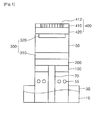
- Fig. 1 is a diagram of a humidifier apparatus using a photocatalyst having an air-cleaning function in accordance with the present invention.
- the housing 50 has a cylindrical shape and is placed upright
- Humidification refers to supply of moisture to a room in a dry condition and requires supply of water 10.
- the humidifier apparatus for humidification, is provided with a water tank 30 which stores the water 10.
- the housing 50 is placed in the apparatus such that a lower portion of the housing is accommodated in the water tank 30.
- the housing 50 is formed with a plurality of inlet holes 55 through which external air can be introduced into the housing 50.
- the inlet holes 55 are formed at a location above the water 10 so as to prevent interference with the water 10.
- the housing 50 is provided therein with an absorption bar 70, which has a lower portion extending into the water 10 and includes a plurality of absorption pores 75 combined in a bar or cylindrical shape so as to absorb the water.
- the absorption bar 70 serves to absorb the water 10 through the plurality of the absorption pores 75.
- the absorption bar 70 is provided with a humidifying filter 100 configured to surround an upper portion of the absorption bar 70.
- the humidifying filter 100 includes a plurality of humidifying pores 110 combined in a honeycomb shape and closely secured to an inner surface of the housing 50.
- the humidifying filter 100 serves to absorb the water 10 from the absorption bar 70.
- the humidifying filter 100 provides a humidification function by allowing the water absorbed from the absorption bar 70 to evaporate.
- the humidifying filter 100 is placed on a holder (not shown), which is formed on the inner surface of the housing 50 to hold the humidifying filter 100.
- the holder protrudes from the inner surface of the housing 50 in a horizontal direction and is configured so as not to obstruct the function of the absorption bar 70 and the function of the humidifying filter 100 receiving the water 10 through the absorption bar 70.
- the water 10 is absorbed into the humidifying filter 100 through the absorption bar 70 and evaporated from the humidifying filter 100, thereby providing moisture to a room.
- An adsorption filter 200 shaped corresponding to the humidifying filter 100 is placed on the humidifying filter 100.
- the adsorption filter 200 is stacked on the humidifying filter 100 and includes a plurality of adsorption pores 210 combined in a honeycomb shape to adsorb dust or contaminants introduced into the housing 50.
- a photocatalyst cleaning unit 300 is placed on the adsorption filter 200.
- the photocatalyst cleaning unit 300 serves to purge the contaminants adsorbed to the adsorption filter 200.
- the photocatalyst cleaning unit 300 is shaped corresponding to the adsorption filter 200 and is stacked on the adsorption filter 200.
- the photocatalyst cleaning unit 300 is provided with a photocatalyst filter 310, which includes a plurality of photocatalyst pores 314 coated with a photocatalyst 312 and combined in a honeycomb shape.
- the photocatalyst cleaning unit 300 includes a light supply unit 320 placed above the photocatalyst filter 310 and emitting light to the photocatalyst 312 in the photocatalyst filter 310 to activate the photocatalyst 312.
- the apparatus includes a discharge unit 400 placed above the photocatalyst cleaning unit 300.
- the discharge unit 400 is placed above the photocatalyst cleaning unit 300 and suctions the moisture supplied from the humidifying filter 100 and air from the housing 50 to discharge the moisture and air to the outside of the housing 50.
- the discharge unit 400 includes a discharge plate 410, which is configured to cover an upper portion of the housing 50 and formed with a plurality of through-holes 412.
- the discharge unit 400 includes a discharge fan 420, which is disposed under the discharge plate 410 and suctions air from the housing 50 to discharge the air to the outside through the discharge plate 410.
- the contaminants when air containing contaminants enters the housing 50, the contaminants are adsorbed to the adsorption filter 200 and purged through the photocatalyst cleaning unit 300 to provide purified air, which in turn is discharged to the outside of the housing 50 through the discharge unit 400.
- Fig. 2 is an exploded perspective view of the humidifier apparatus using a photocatalyst having an air-cleaning function in accordance with the present invention.
- FIG. 2 the components of the humidifier apparatus shown in Fig. 1 are dissembled. Now, these components will be described in more detail.
- the water tank 30 stores water 10, and the housing 50 having a cylindrical shape stands upright and has a lower portion extending into the water 10.
- the housing 50 receives the absorption bar 70, which includes the plurality of absorption pores 75 combined in a bar shape.
- the absorption bar 70 has a lower portion received in the water 10.
- the absorption pores 75 of the absorption bar 70 efficiently absorb water 10 through capillary action, whereby the entirety of the absorption bar 70 can absorb the water 10.
- the absorption bar 70 is connected at the upper portion thereof to the humidifying filter 100.
- the humidifying filter 100 is connected to the upper portion of the absorption bar 70 to surround an outer periphery of the upper portion of the absorption bar 70, includes the plurality of humidifying pores 110 combined in a honeycomb shape, and is closely secured to the inner surface of the housing 50.
- the humidifying pores 110 are in close contact with each other to achieve efficient absorption of the water 10 from the absorption bar 70 and are arranged along the circular inner surface of the housing 50 to constitute the humidifying filter 100.
- the housing 50 is formed with inlet holes 55 through which external air can be introduced into the housing 50.
- Such inlet holes 55 are formed at a location of the housing above an upper level of the water 10 contained in the water tank 30 and below a lower side of the humidifying filter 100.
- the location of the inlet holes 55 is determined so as to allow air introduced into the housing 50 through the inlet holes 55 to supply moisture to a room while evaporating the water suctioned into the humidifying filter 100.
- the adsorption filter 200 is placed on the humidifying filter 100.
- the adsorption filter 200 has a shape corresponding to the shape of the humidifying filter 100, includes the plurality of adsorption pores 210 combined in a honeycomb shape, and is closely secured to the inner surface of the housing 50.
- the adsorption pores 210 are in close contact with each other to achieve efficient adsorption of contaminants in air introduced into the housing 50 through the inlet holes 55 and are arranged along the circular inner surface of the housing 50 to constitute the adsorption filter 100.
- the plural adsorption pores 210 are combined in a honeycomb shape and efficiently adsorb contaminants such as volatile organic compounds (VOCs) from air introduced into the housing 50.
- VOCs volatile organic compounds
- the housing 50 is formed in a column shape and both the humidifying pores 110 of the humidifying filter 100 and the adsorption pores 210 of the adsorption filter 200 are formed in a honeycomb structure, thereby improving space utilization per unit area.
- the humidifying pores 110 or the adsorption pores 210 have a circular cross-section, a space can be created at a portion other than portions where circles meet each other, even in the case where the plural humidifying pores 110 or adsorption pores 210 are in close contact with each other.
- each of the humidifying pores 110 and the adsorption pores 210 has a honeycomb-shaped cross-section, for example, a hexagonal structure.
- each of the humidifying pores 110 or each of the adsorption pores 210 can be in close contact with other hexagonal humidifying or adsorption pores without creating a space between the pores.
- the humidifying pores 110 or the adsorption pores 210 having a honeycomb-shaped hexagonal cross-section can be brought into close and dense contact with each other without creating a space therebetween.
- the humidifying pores 110 of the humidifying filter 100 and the adsorption pores 210 of the adsorption filter 200 are combined in a honeycomb structure and disposed in a close and dense arrangement, thereby providing optimal space utilization.
- the photocatalyst cleaning unit 300 includes a photocatalyst filter 310 stacked on the adsorption filter 200, and a light supply unit 320 stacked above the photocatalyst filter 310.
- the plural photocatalyst pores 314 coated with the photocatalyst 312 are brought into close contact with each other and combined in a honeycomb shape so as to allow contaminants adsorbed to the adsorption filter 200 to be efficiently purged, and are arranged along the circular inner surface of the housing 50, thereby constituting the photocatalyst filter 310.
- the plurality of photocatalyst pores 314 is formed to receive a large amount of the photocatalyst 312 in a narrow space.
- the light supply unit 320 emits light to the photocatalyst 312 coated on the photocatalyst filter 310 to activate the photocatalyst 312.
- the light supply unit 320 may include a light emitting unit 322, which is constituted by a light emitting diode (LED).
- a light emitting unit 322 which is constituted by a light emitting diode (LED).
- the LED of the light emitting unit 322 is illustrated as one embodiment and the light emitting unit 322 may include a variety of lamps (not shown) as needed.
- the light emitting unit 322 may emit visible or UV (ultraviolet) light through a separate lamp capable of emitting both visible and UV light.
- the light emitting unit 322 may emit UV or visible light.
- the photocatalyst 312 refers to a material which can receive light to promote chemical reaction, and such reaction can be called a photochemical reaction.
- the photocatalyst 312 may employ a visible light catalyst which can be activated to promote reaction by visible light, or a UV light catalyst (titanium dioxide (TiO 2 which can be activated to promote the reaction by UV light according to the kind of light emitted from the LED.
- a visible light catalyst which can be activated to promote reaction by visible light
- a UV light catalyst titanium dioxide (TiO 2 which can be activated to promote the reaction by UV light according to the kind of light emitted from the LED.
- TiO 2 titanium dioxide
- the photocatalyst 312 serves to decompose contaminants including a toxic substance within the housing 50 while providing an anti-bacterial function and an anti-fouling function.
- discharge unit 400 is place on the photocatalyst cleaning unit 300.
- the discharge unit 400 includes the discharge plate 410, which is configured to cover the upper portion of the housing 50 and formed with the plurality of through-holes 412.
- the discharge unit 400 includes the discharge fan 420 disposed under the discharge plate 410 to suction air from the housing 50 and discharge the air to the outside through the discharge plate 410.
- the discharge plate 410 allows only purged moisture to be discharged to the outside of the housing 50 through the through-holes 412 of the discharge plate 410.
- moisture evaporated from the humidifying filter 100 is purged while passing through the adsorption filter 200 and the photocatalyst cleaning unit 300.
- the discharge fan 420 allows the purged moisture to be more efficiently discharged through the discharge plate 410.
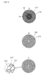
- Fig. 3 shows cross-sectional views of main parts of the humidifier apparatus using a photocatalyst having an air-cleaning function in accordance with the present invention.
- a cross-sectional view A of the absorption bar 70 including the absorption pores 75 and the humidifying filter 100 including the humidifying pores 110 is shown.
- a cross-sectional view B of the adsorption filter 200 including the adsorption pores 210 is shown.
- a cross-sectional view C of the photocatalyst filter 310 including the photocatalyst 312 and the photocatalyst pores 314 is shown.
- the plurality of absorption pores 75 is combined to have a circular cross-section so as to absorb water.
- the plurality of humidifying pores 110 is combined to have a circular cross-section.
- the absorption pores 75 may have a diameter of 1 ⁇ m to 20 ⁇ m.
- the adsorption pores 75 can provide insufficient capillary action, thereby reducing the amount of water suctioned into the absorption pores 75.
- the humidifying pores 110 may have a diameter of 20 ⁇ m to 35 ⁇ m.
- a humidifying media can suffer from rapid reduction in lifespan due to deposition of inorganic ions in water.
- the humidifying filter 100 is unlikely to absorb water and thus cannot function properly.
- the absorption bar 70 and the humidifying filter 100 may be formed of glass fibers, pulps, or titanium dioxide (TiO 2 ).
- a cross-section of the adsorption filter 200 including the adsorption pores 210 is shown.
- the plurality of the adsorption pores 210 is combined to have a circular cross-section.
- the adsorption filter 200 including the plurality of the adsorption pores 210 serves to adsorb moisture introduced into the housing 50.
- the adsorption filter 200 employs an adsorbent, and the plurality of adsorption pores 210 is provided to increase an adsorption area of the contaminants with respect to the adsorbent.
- the adsorbent may be selected from among activated carbon, diatomite, zeolite, silica gel, starch, bentonite, alumina, and the like.
- the plurality of the photocatalyst pores 314 is combined to have a circular cross-section.
- the photocatalyst 312 is spray-coated on the surfaces of the photocatalyst pores 314.
- the photocatalyst 312 may be formed of titanium dioxide (TiO 2 ), and provided a visible light source, the photocatalyst 312 may be formed of TiO 2 or a visible light catalyst loaded with a noble metal, such as Pt, Au, Ag, and the like.
- the photocatalyst 312 serves to decompose contaminants including toxic substances within the housing 50 through oxidation while providing an anti-bacterial function and an anti-fouling function.
- the photocatalyst 312 promotes chemical reaction upon receiving light.
- the photocatalyst is further activated through photochemical reaction when exposed to light in UV or visible light wavelength bands.
- Fig. 4 is an exploded perspective view of a humidifier apparatus using a photocatalyst having an air-cleaning function in accordance with one embodiment of the present invention.
- FIG. 4 other components are added to the humidifier apparatus shown in Fig. 2 .
- a housing 50 having a cylindrical shape is provided with inlet holes 55, through which external air is introduced into the housing 50, and has a lower portion submerged in water 10 which fills a water tank 30.
- the housing 50 is provided with an absorption bar 70, which includes a plurality of absorption pores 75 combined to absorb the water 10 through capillary action.
- a humidifying filter 100 is connected to an upper portion of the absorption bar 70 to surround an outer periphery of the upper portion of the absorption bar 70 and includes a plurality of humidifying pores 110 combined in a honeycomb shape.
- the humidifying filter 100 is closely secured to an inner surface of the housing 50.
- Such a humidifying filter 100 absorbs the water 10 through the absorption bar 70 and supplies moisture into a room while evaporating the water 10.
- an adsorption filter 200 having a shape corresponding to the humidifying filter 100 is stacked on the humidifying filter 100.
- the adsorption filter 200 also includes a plurality of adsorption pores 210 combined in a honeycomb shape and is closely secured to the inner surface of the housing 50.
- the adsorption pores 210 serve to adsorb contaminants in air introduced into the housing through the inlet holes 55.
- the adsorption filter 200 employs an adsorbent.
- the plurality of adsorption pores 210 is provided to increase an adsorption area of contaminants with respect to the adsorbent.
- the plurality of adsorption pores 210 combined in a honeycomb shape has a function of efficiently adsorbing dust or contaminants introduced into the housing 50.
- the contaminants adsorbed to the adsorption filter 200 are decomposed by the photocatalyst cleaning unit 300.
- the photocatalyst cleaning unit 300 includes a photocatalyst filter 310 stacked on the adsorption filter 200, and a light supply unit 320 stacked above the photocatalyst filter 310
- the photocatalyst filter 310 includes the plurality of the photocatalyst pores 314 combined to have a circular shape.
- the photocatalyst pores 314 are coated with the photocatalyst 312 by spraying the photocatalyst 312 onto the surfaces of the photocatalyst pores 314.
- contaminants adsorbed to the adsorption filter 200 can be efficiently decomposed through the photocatalyst filter 310 in which the plurality of photocatalyst pores 314 coated with the photocatalyst 312 is combined.
- the light supply unit 320 includes a light emitting unit 322, which is constituted by a light emitting diode (LED).
- a light emitting unit 322 which is constituted by a light emitting diode (LED).
- the light emitting unit 322 may emit UV light through a variety of lamps, as needed.
- the light supply unit 320 includes a power controller 324 which controls the light emitting unit 322 to be operated by alternating power and controls the light emitting unit 322 to be turned on/off.
- the power controller 324 controls the intensity of light emitted from the light emitting unit 322 to the photocatalyst filter 310 to regulate activation of the photocatalyst 312 in the photocatalyst filter 310.
- the contaminants adsorbed to the adsorption filter 200 can be efficiently decomposed in the photocatalyst filter 310 by controlling the light emitting unit 322 through the power controller 324.
- the light emitting unit 322 emits light in UV and visible wavelength bands to activate the photocatalyst 312.
- the photocatalyst 312 may be composed of titanium dioxide (TiO 2 ) and serve to decompose the contaminants in the housing 50 through oxidation while providing an anti-bacterial function and an anti-fouling function.
- a discharge unit 400 is stacked on the photocatalyst cleaning unit 300.
- the discharge unit 400 includes a discharge plate 410, which is configured to cover an upper portion of the housing 50 and formed with a plurality of through-holes 412.
- the discharge unit 400 includes a discharge fan 420 disposed under the discharge plate 410 to suction air from the housing 50 and discharge the air to the outside through the discharge plate 410.
- the discharge unit 400 further includes a guide piece 430 connected to an upper portion of the discharge plate 410 to guide flow of the air discharged through the through-holes 412.
- the guide piece 430 Upon discharge of air to the outside from the housing 50, the guide piece 430 guides the flow of the air while rotating in a state of being coupled to the upper portion of the discharge plate 410.
- the discharge unit 400 further includes a discharge controller 440 placed outside and controlling the discharge fan 420 to regulate the amount of air discharged from the housing 50 to the outside.
- the discharge controller 440 controls the rotating speed of the discharge fan 420 to control the amount of air discharged from the housing 50 to the outside.
- Fig. 5 is an exploded perspective view of a humidifier apparatus using a photocatalyst having an air-cleaning function in accordance with another embodiment of the present invention.
- the humidifier apparatus includes a housing 50 having a different structure from the above embodiment.
- the housing 50 may have a square pillar shape.
- the housing 50 has a lower portion partially received in a water tank 30 which stores water 10.
- the housing 50 is formed with a plurality of inlet holes 55 through which external air can be introduced into the housing 50, in which the inlet holes are formed at a location of the housing between an upper level of the water 10 in the water tank 30 and a humidifying filter 100.
- the humidifying filter 100 has a shape corresponding to an inner surface of the housing 50 and is brought into close contact therewith.
- the humidifying filter 100 serves to absorb the water 10 in order to supply moisture into a room.
- an adsorption filter 200 having a shape corresponding to the humidifying filter 100 is stacked on the humidifying filter 100.
- the adsorption filter 200 serves to adsorb contaminants such as dust in air introduced into the housing 50 through the inlet holes 55.
- a photocatalyst cleaning unit 300 is placed on the adsorption filter 200 to purge the contaminants adsorbed to the adsorption filter 200.
- Such a photocatalyst cleaning unit 300 serves to supply purified air into a room through the housing 50 by purging the contaminants adsorbed to the adsorption filter 200.
- air purified by the photocatalyst cleaning unit 300 is discharged from the housing 50 through the guide piece 430.
- the guide piece 430 can be rotated while being coupled to an upper portion of the housing 50, it is possible to discharge the air from the housing 50 in various directions as needed.
- the housing 50 may have other shapes, for example, a polygonal pillar shape.
- the humidifying filter 100, the adsorption filter 200 and the photocatalyst filter 310 be configured corresponding to the shape of the inner surface of the housing 50.
- a humidifier apparatus using a photocatalyst having an air-cleaning function in accordance with the present invention (example) and a humidifier apparatus having an air-cleaning function through generation of anions (comparative example) were compared.
- the humidifier apparatuses of the example and the comparative example were operated for a total of 100 hours, and then were evaluated as to air-cleaning function, humidifying amount and noise generation through operation for 10 hours.
- Table 1 Air-cleaning function Humidifying amount (g/hr) Noise generation Example Excellent about 80 g/hr No noise Comparative Example Good (03 (ozone) detected) about 80 g/hr Noise generated
- both the apparatuses of the example and the comparative example provided an air-cleaning function of removing indoor toxic substances and bacteria
- the apparatus of the comparative example underwent gradual reduction in generation of anions over time and generated ozone O 3 , which is toxic to humans.
- the apparatus of the example maintained an excellent air-cleaning function over time.
- the apparatus of the example generated no substantial noise in operation.
- the apparatus of the comparative example generated motor noise. There was a significant difference in terms of noise generation between the example and the comparative example when compared by an observer.
- the humidifier apparatus using a photocatalyst having an air-cleaning function according to the present invention provides excellent effects in terms of air-cleaning, humidification and noise generation, as compared with existing humidifier apparatuses having an air-cleaning function.
- the apparatus according to the present invention is manufactured in a column type structure, thereby providing an advantage of good space utilization.
Landscapes
- Engineering & Computer Science (AREA)
- Chemical & Material Sciences (AREA)
- General Engineering & Computer Science (AREA)
- Mechanical Engineering (AREA)
- Combustion & Propulsion (AREA)
- Chemical Kinetics & Catalysis (AREA)
- General Chemical & Material Sciences (AREA)
- Health & Medical Sciences (AREA)
- Oil, Petroleum & Natural Gas (AREA)
- Environmental & Geological Engineering (AREA)
- Analytical Chemistry (AREA)
- Biomedical Technology (AREA)
- General Health & Medical Sciences (AREA)
- Animal Behavior & Ethology (AREA)
- Dispersion Chemistry (AREA)
- Public Health (AREA)
- Veterinary Medicine (AREA)
- Life Sciences & Earth Sciences (AREA)
- Epidemiology (AREA)
- Physics & Mathematics (AREA)
- Fluid Mechanics (AREA)
- Disinfection, Sterilisation Or Deodorisation Of Air (AREA)
- Catalysts (AREA)
- Air Humidification (AREA)
Abstract
Description
- The present invention relates to a humidifier apparatus using a photocatalyst having an air-cleaning function, and more particularly, to a humidifier apparatus using a photocatalyst, which can provide an air-cleaning function and a humidification function while minimizing energy consumption.
- Currently, most people spend 90% of the day in a room and are exposed to a variety of gaseous contaminants, such as volatile organic compounds, radon, and microorganisms.
- Thus, it is very important to supply clean air into a room through purification of indoor air.
- Accordingly, the interior of a house, office, school, or the like is generally provided with an air cleaner for purification of indoor air.
- In addition, although an air cleaner and a humidifier have been manufactured as separate products, a product combining an air-cleaning function and a humidification function has recently been introduced to the market to satisfy consumer demand.
- Conventionally, an anion generating type system is used to provide moisture while purifying indoor air.
- However, the anion generating type system adopts electrolysis by generating a spark upon application of high voltage to metallic electrode rods, and thus has problems such as anion emission and generation of activated oxygen and ozone.
- In addition, anion generating efficiency can be significantly reduced when dust or foreign matter is attached to a surface of a discharge plate.
- Further, a system of generating anions through decomposition of water into fine droplets through centrifugation has a complicated structure and produces severe motor noise.
- An aspect of the present invention is to provide a humidifier apparatus using a photocatalyst having an air-cleaning function, which can provide moisture while purifying indoor air and can be semi-permanently used using a photocatalyst.
- Another aspect of the present invention is to provide a humidifier apparatus using a photocatalyst having an air-cleaning function, which permits easy installation and disassembly and can reduce energy consumption in use.
- A further aspect of the present invention is to provide a humidifier apparatus using a photocatalyst having an air-cleaning function, which does not generate noise in use while improving indoor environment.
- Yet another aspect of the present invention is to provide a humidifier apparatus using a photocatalyst having an air-cleaning function, which includes a column type housing to permit optimal utilization of space per unit area and filter pores disposed inside the apparatus and each having a close and dense honeycomb shape.
- In accordance with one aspect of the present invention, a humidifier apparatus using a photocatalyst having an air-cleaning function includes:
- a housing, which has a lower portion being received in a water tank for storing water, and includes an inlet hole for intake of external air into the housing; an absorption bar being disposed within the housing so as to allow a lower portion of the absorption bar to be submerged in the water, whihc includes a plurality of adsorption pores combined to absorb the water; a humidifying filter being secured to an inner surface of the housing and covering an upper portion of the absorption bar, which includes a plurality of humidifying pores combined with each other; an adsorption filter being stacked on the humidifying filter, which includes a plurality of adsorption pores combined with each other to adsorb foreign matter introduced into the housing; a photocatalyst cleaning unit being stacked on the adsorption filter, which purges the foreign matter adsorbed to the adsorption filter; and a discharge unit being disposed above the photocatalyst cleaning unit, which absorbs the moisture supplied from the humidifying filter and air from the housing, and discharges the absorbed moisture and air to an outside of the housing.
- The photocatalyst cleaning unit may include a photocatalyst filter being stacked on the adsorption filter, which includes a plurality of photocatalyst pores coated with a photocatalyst and combined in a honeycomb shape so as to purge the foreign matter adsorbed to the adsorption filter; and a light supply unit being disposed above the photocatalyst filter, which emits light to the photocatalyst included in the photocatalyst filter to activate the photocatalyst.
- The light supply unit may include a light emitting unit, which comprises a light emitting diode (LED); and a power controller controlling the light emitting unit to be operated by alternating power and controlling the light emitting unit to be turned on/off.
- The discharge unit may include a discharge plate, which covers an upper portion of the housing, and includes a plurality of through-holes formed therein; and a discharge fan being disposed under the discharge plate, which suctions air from the housing, and discharges the air through the discharge plate.
- The discharge unit may further include a guide piece being connected to an upper portion of the discharge plate, which guides flow of the air discharged through the through-holes.
- The discharge unit may further include a discharge controller, which regulates an amount of air discharged from the housing to the outside by outside controlling the discharge fan.
- The housing may have a cylindrical shape.
- The inlet hole may be formed at a location of the housing below the humidifying filter and above the water.
- The humidifier apparatus according to the present invention a photocatalyst with a semi-permanent lifespan and thus has high energy efficiency, thereby providing economic feasibility through reduction in operating costs.
- The humidifier apparatus according to the present invention can supply moisture into a dry room while purifying indoor air, and facilitates installation and disassembly thereof.
- The humidifier apparatus according to the present invention does not generate noise in use while maintaining a humidification function and an air-cleaning function.
- The humidifier apparatus according to the present invention has a column type outer appearance and includes filters arranged within the housing and including pores closely and densely combined in a honeycomb shape, thereby enabling efficient utilization of space per unit area.
-
-
Fig. 1 is a diagram of a humidifier apparatus using a photocatalyst having an air-cleaning function in accordance with the present invention. -
Fig. 2 is an exploded perspective view of the humidifier apparatus using a photocatalyst having an air-cleaning function in accordance with the present invention. -
Fig. 3 shows cross-sectional views of main parts of the humidifier apparatus using a photocatalyst having an air-cleaning function in accordance with the present invention. -
Fig. 4 is an exploded perspective view of a humidifier apparatus using a photocatalyst having an air-cleaning function in accordance with one embodiment of the present invention. -
Fig. 5 is an exploded perspective view of a humidifier apparatus using a photocatalyst having an air-cleaning function in accordance with another embodiment of the present invention. - In the following detailed description of various specific embodiments in which the present invention may be practiced, reference is made to the accompanying drawings by way of illustration. These embodiments will be described so as to provide thorough understanding of the present invention such that the present invention can be practiced by those skilled in the art. It should be understood that the various embodiments of the invention, although different, are not necessarily mutually exclusive. For example, particular features, structures or characteristics described in one embodiment may be included in other embodiments without departing from the spirit and scope of the present invention. Furthermore, it should be understood that embodiments of the invention may be implemented using different technologies. Further, it should be understood that locations or arrangements of individual components in the respective embodiments can be changed without departing from the spirit and scope of the present invention. The following detailed description is, therefore, not to be taken in a limiting sense, and the scope of the present invention is defined only by the appended claims, along with the full scope of equivalents to which such claims are entitled. In the drawings, like reference numerals denote the same or similar components throughout several aspects, and areas, thicknesses, shapes and the like can be exaggerated for convenience in description.
- Now, exemplary embodiments of the present invention will be described in detail with reference to the accompanying drawings so as to allow the present invention to be easily practiced by those skilled in the art to which the present invention pertains.
- Here, it should be understood that the technical features of a humidifier apparatus using a photocatalyst having an air-cleaning function according to the present invention, particularly, the technical features of a humidifying filter and a photocatalyst filter, may be applied to other fields directed to, for example, providing an air-cleaning function and a humidification function while minimizing energy consumption.
-
Fig. 1 is a diagram of a humidifier apparatus using a photocatalyst having an air-cleaning function in accordance with the present invention. - Referring to
Fig. 1 , ahousing 50 and components in thehousing 50 will be described. Thehousing 50 has a cylindrical shape and is placed upright - Humidification refers to supply of moisture to a room in a dry condition and requires supply of
water 10. - For humidification, the humidifier apparatus according to the invention is provided with a
water tank 30 which stores thewater 10. - The
housing 50 is placed in the apparatus such that a lower portion of the housing is accommodated in thewater tank 30. - In addition, the
housing 50 is formed with a plurality ofinlet holes 55 through which external air can be introduced into thehousing 50. - Here, the
inlet holes 55 are formed at a location above thewater 10 so as to prevent interference with thewater 10. - Further, the
housing 50 is provided therein with anabsorption bar 70, which has a lower portion extending into thewater 10 and includes a plurality ofabsorption pores 75 combined in a bar or cylindrical shape so as to absorb the water. - The
absorption bar 70 serves to absorb thewater 10 through the plurality of theabsorption pores 75. - Here, the
absorption bar 70 is provided with ahumidifying filter 100 configured to surround an upper portion of theabsorption bar 70. - The
humidifying filter 100 includes a plurality of humidifyingpores 110 combined in a honeycomb shape and closely secured to an inner surface of thehousing 50. - The humidifying
filter 100 serves to absorb thewater 10 from theabsorption bar 70. - As such, the
humidifying filter 100 provides a humidification function by allowing the water absorbed from theabsorption bar 70 to evaporate. - Preferably, the
humidifying filter 100 is placed on a holder (not shown), which is formed on the inner surface of thehousing 50 to hold thehumidifying filter 100. - Preferably, the holder protrudes from the inner surface of the
housing 50 in a horizontal direction and is configured so as not to obstruct the function of theabsorption bar 70 and the function of thehumidifying filter 100 receiving thewater 10 through theabsorption bar 70. - As such, in the apparatus, the
water 10 is absorbed into thehumidifying filter 100 through theabsorption bar 70 and evaporated from thehumidifying filter 100, thereby providing moisture to a room. - An
adsorption filter 200 shaped corresponding to thehumidifying filter 100 is placed on thehumidifying filter 100. - The
adsorption filter 200 is stacked on thehumidifying filter 100 and includes a plurality ofadsorption pores 210 combined in a honeycomb shape to adsorb dust or contaminants introduced into thehousing 50. - In addition, a
photocatalyst cleaning unit 300 is placed on theadsorption filter 200. - The
photocatalyst cleaning unit 300 serves to purge the contaminants adsorbed to theadsorption filter 200. - The
photocatalyst cleaning unit 300 is shaped corresponding to theadsorption filter 200 and is stacked on theadsorption filter 200. Thephotocatalyst cleaning unit 300 is provided with aphotocatalyst filter 310, which includes a plurality ofphotocatalyst pores 314 coated with aphotocatalyst 312 and combined in a honeycomb shape. - Further, the
photocatalyst cleaning unit 300 includes alight supply unit 320 placed above thephotocatalyst filter 310 and emitting light to thephotocatalyst 312 in thephotocatalyst filter 310 to activate thephotocatalyst 312. - Further, the apparatus includes a
discharge unit 400 placed above thephotocatalyst cleaning unit 300. - The
discharge unit 400 is placed above thephotocatalyst cleaning unit 300 and suctions the moisture supplied from thehumidifying filter 100 and air from thehousing 50 to discharge the moisture and air to the outside of thehousing 50. - Here, the
discharge unit 400 includes adischarge plate 410, which is configured to cover an upper portion of thehousing 50 and formed with a plurality of through-holes 412. - Further, the
discharge unit 400 includes adischarge fan 420, which is disposed under thedischarge plate 410 and suctions air from thehousing 50 to discharge the air to the outside through thedischarge plate 410. - As such, when air containing contaminants enters the
housing 50, the contaminants are adsorbed to theadsorption filter 200 and purged through thephotocatalyst cleaning unit 300 to provide purified air, which in turn is discharged to the outside of thehousing 50 through thedischarge unit 400. -
Fig. 2 is an exploded perspective view of the humidifier apparatus using a photocatalyst having an air-cleaning function in accordance with the present invention. - Referring to
Fig. 2 , the components of the humidifier apparatus shown inFig. 1 are dissembled. Now, these components will be described in more detail. - The
water tank 30stores water 10, and thehousing 50 having a cylindrical shape stands upright and has a lower portion extending into thewater 10. - The
housing 50 receives theabsorption bar 70, which includes the plurality ofabsorption pores 75 combined in a bar shape. - Here, the
absorption bar 70 has a lower portion received in thewater 10. - With this configuration, the absorption pores 75 of the
absorption bar 70 efficiently absorbwater 10 through capillary action, whereby the entirety of theabsorption bar 70 can absorb thewater 10. - In addition, the
absorption bar 70 is connected at the upper portion thereof to thehumidifying filter 100. - The
humidifying filter 100 is connected to the upper portion of theabsorption bar 70 to surround an outer periphery of the upper portion of theabsorption bar 70, includes the plurality ofhumidifying pores 110 combined in a honeycomb shape, and is closely secured to the inner surface of thehousing 50. - The humidifying pores 110 are in close contact with each other to achieve efficient absorption of the
water 10 from theabsorption bar 70 and are arranged along the circular inner surface of thehousing 50 to constitute thehumidifying filter 100. - In particular, the
housing 50 is formed with inlet holes 55 through which external air can be introduced into thehousing 50. - Such inlet holes 55 are formed at a location of the housing above an upper level of the
water 10 contained in thewater tank 30 and below a lower side of thehumidifying filter 100. - That is, the location of the inlet holes 55 is determined so as to allow air introduced into the
housing 50 through the inlet holes 55 to supply moisture to a room while evaporating the water suctioned into thehumidifying filter 100. - The
adsorption filter 200 is placed on thehumidifying filter 100. - The
adsorption filter 200 has a shape corresponding to the shape of thehumidifying filter 100, includes the plurality ofadsorption pores 210 combined in a honeycomb shape, and is closely secured to the inner surface of thehousing 50. - That is, the adsorption pores 210 are in close contact with each other to achieve efficient adsorption of contaminants in air introduced into the
housing 50 through the inlet holes 55 and are arranged along the circular inner surface of thehousing 50 to constitute theadsorption filter 100. - As a result, in the
adsorption filter 200, the plural adsorption pores 210 are combined in a honeycomb shape and efficiently adsorb contaminants such as volatile organic compounds (VOCs) from air introduced into thehousing 50. - With such a configuration, contaminants adsorbed to the
adsorption filter 200 are purged through thephotocatalyst cleaning unit 300 on theadsorption filter 200, so that purified air can be finally supplied from thephotocatalyst cleaning unit 300. - In particular, the
housing 50 is formed in a column shape and both the humidifying pores 110 of thehumidifying filter 100 and the adsorption pores 210 of theadsorption filter 200 are formed in a honeycomb structure, thereby improving space utilization per unit area. - Further, when the humidifying pores 110 or the adsorption pores 210 have a circular cross-section, a space can be created at a portion other than portions where circles meet each other, even in the case where the plural humidifying pores 110 or
adsorption pores 210 are in close contact with each other. - In the present invention, each of the humidifying pores 110 and the adsorption pores 210 has a honeycomb-shaped cross-section, for example, a hexagonal structure.
- With such a honeycomb-shaped hexagonal cross-section, each of the humidifying pores 110 or each of the adsorption pores 210 can be in close contact with other hexagonal humidifying or adsorption pores without creating a space between the pores.
- Accordingly, the humidifying pores 110 or the adsorption pores 210 having a honeycomb-shaped hexagonal cross-section can be brought into close and dense contact with each other without creating a space therebetween.
- Further, the humidifying pores 110 of the
humidifying filter 100 and the adsorption pores 210 of theadsorption filter 200 are combined in a honeycomb structure and disposed in a close and dense arrangement, thereby providing optimal space utilization. - Further, the
photocatalyst cleaning unit 300 includes aphotocatalyst filter 310 stacked on theadsorption filter 200, and alight supply unit 320 stacked above thephotocatalyst filter 310. - The plural photocatalyst pores 314 coated with the
photocatalyst 312 are brought into close contact with each other and combined in a honeycomb shape so as to allow contaminants adsorbed to theadsorption filter 200 to be efficiently purged, and are arranged along the circular inner surface of thehousing 50, thereby constituting thephotocatalyst filter 310. - Here, the plurality of photocatalyst pores 314 is formed to receive a large amount of the
photocatalyst 312 in a narrow space. - The
light supply unit 320 emits light to thephotocatalyst 312 coated on thephotocatalyst filter 310 to activate thephotocatalyst 312. - The
light supply unit 320 may include alight emitting unit 322, which is constituted by a light emitting diode (LED). - Here, it should be understood that the LED of the
light emitting unit 322 is illustrated as one embodiment and thelight emitting unit 322 may include a variety of lamps (not shown) as needed. - In particular, the
light emitting unit 322 may emit visible or UV (ultraviolet) light through a separate lamp capable of emitting both visible and UV light. - As such, the
light emitting unit 322 may emit UV or visible light. - In particular, the
photocatalyst 312 refers to a material which can receive light to promote chemical reaction, and such reaction can be called a photochemical reaction. - Here, the
photocatalyst 312 may employ a visible light catalyst which can be activated to promote reaction by visible light, or a UV light catalyst (titanium dioxide (TiO2 which can be activated to promote the reaction by UV light according to the kind of light emitted from the LED. Thephotocatalyst 312 serves to decompose contaminants including a toxic substance within thehousing 50 while providing an anti-bacterial function and an anti-fouling function. - Further, the
discharge unit 400 is place on thephotocatalyst cleaning unit 300. - The
discharge unit 400 includes thedischarge plate 410, which is configured to cover the upper portion of thehousing 50 and formed with the plurality of through-holes 412. - Further, the
discharge unit 400 includes thedischarge fan 420 disposed under thedischarge plate 410 to suction air from thehousing 50 and discharge the air to the outside through thedischarge plate 410. - The
discharge plate 410 allows only purged moisture to be discharged to the outside of thehousing 50 through the through-holes 412 of thedischarge plate 410. Here, moisture evaporated from thehumidifying filter 100 is purged while passing through theadsorption filter 200 and thephotocatalyst cleaning unit 300. - The
discharge fan 420 allows the purged moisture to be more efficiently discharged through thedischarge plate 410. -
Fig. 3 shows cross-sectional views of main parts of the humidifier apparatus using a photocatalyst having an air-cleaning function in accordance with the present invention. - In
Fig. 3 , a cross-sectional view A of theabsorption bar 70 including the absorption pores 75 and thehumidifying filter 100 including the humidifying pores 110 is shown. - In addition, a cross-sectional view B of the
adsorption filter 200 including the adsorption pores 210 is shown. - Further, a cross-sectional view C of the
photocatalyst filter 310 including thephotocatalyst 312 and the photocatalyst pores 314 is shown. - Referring to the cross-sectional view A, the plurality of absorption pores 75 is combined to have a circular cross-section so as to absorb water.
- In addition, in the
humidifying filter 100 surrounding part of theabsorption bar 70, the plurality of humidifying pores 110 is combined to have a circular cross-section. - Here, the absorption pores 75 may have a diameter of 1 µm to 20 µm.
- If the diameter of the absorption pores 75 exceeds 20 µm, the adsorption pores can provide insufficient capillary action, thereby reducing the amount of water suctioned into the absorption pores 75.
- Further, the humidifying pores 110 may have a diameter of 20 µm to 35 µm.
- If the diameter of the humidifying pores 110 is less than 20 µm, a humidifying media can suffer from rapid reduction in lifespan due to deposition of inorganic ions in water.
- If the diameter of the humidifying pores 110 exceeds 35 µm, the
humidifying filter 100 is unlikely to absorb water and thus cannot function properly. - In addition, the
absorption bar 70 and thehumidifying filter 100 may be formed of glass fibers, pulps, or titanium dioxide (TiO2). - Referring to the cross-sectional view B, a cross-section of the
adsorption filter 200 including the adsorption pores 210 is shown. - Here, in the
adsorption filter 200, the plurality of the adsorption pores 210 is combined to have a circular cross-section. - In addition, the
adsorption filter 200 including the plurality of the adsorption pores 210 serves to adsorb moisture introduced into thehousing 50. - Here, the
adsorption filter 200 employs an adsorbent, and the plurality of adsorption pores 210 is provided to increase an adsorption area of the contaminants with respect to the adsorbent. - The adsorbent may be selected from among activated carbon, diatomite, zeolite, silica gel, starch, bentonite, alumina, and the like.
- Referring to the cross-sectional view C, a cross-section of the
photocatalyst filter 310 including the photocatalyst pores 314 is shown. - Here, in the
photocatalyst filter 310, the plurality of the photocatalyst pores 314 is combined to have a circular cross-section. - In addition, the
photocatalyst 312 is spray-coated on the surfaces of the photocatalyst pores 314. - Here, provided a UV light source, the
photocatalyst 312 may be formed of titanium dioxide (TiO2), and provided a visible light source, thephotocatalyst 312 may be formed of TiO2 or a visible light catalyst loaded with a noble metal, such as Pt, Au, Ag, and the like. Thephotocatalyst 312 serves to decompose contaminants including toxic substances within thehousing 50 through oxidation while providing an anti-bacterial function and an anti-fouling function. - The
photocatalyst 312 promotes chemical reaction upon receiving light. Thus, the photocatalyst is further activated through photochemical reaction when exposed to light in UV or visible light wavelength bands. -
Fig. 4 is an exploded perspective view of a humidifier apparatus using a photocatalyst having an air-cleaning function in accordance with one embodiment of the present invention. - Referring to
Fig. 4 , other components are added to the humidifier apparatus shown inFig. 2 . - A
housing 50 having a cylindrical shape is provided with inlet holes 55, through which external air is introduced into thehousing 50, and has a lower portion submerged inwater 10 which fills awater tank 30. - The
housing 50 is provided with anabsorption bar 70, which includes a plurality ofabsorption pores 75 combined to absorb thewater 10 through capillary action. - Further, a
humidifying filter 100 is connected to an upper portion of theabsorption bar 70 to surround an outer periphery of the upper portion of theabsorption bar 70 and includes a plurality ofhumidifying pores 110 combined in a honeycomb shape. Thehumidifying filter 100 is closely secured to an inner surface of thehousing 50. - Such a
humidifying filter 100 absorbs thewater 10 through theabsorption bar 70 and supplies moisture into a room while evaporating thewater 10. - Further, an
adsorption filter 200 having a shape corresponding to thehumidifying filter 100 is stacked on thehumidifying filter 100. - The
adsorption filter 200 also includes a plurality ofadsorption pores 210 combined in a honeycomb shape and is closely secured to the inner surface of thehousing 50. - The adsorption pores 210 serve to adsorb contaminants in air introduced into the housing through the inlet holes 55.
- Here, the
adsorption filter 200 employs an adsorbent. - The plurality of adsorption pores 210 is provided to increase an adsorption area of contaminants with respect to the adsorbent.
- As such, in the
adsorption filter 200, the plurality ofadsorption pores 210 combined in a honeycomb shape has a function of efficiently adsorbing dust or contaminants introduced into thehousing 50. - Further, the contaminants adsorbed to the
adsorption filter 200 are decomposed by thephotocatalyst cleaning unit 300. - Here, the
photocatalyst cleaning unit 300 includes aphotocatalyst filter 310 stacked on theadsorption filter 200, and alight supply unit 320 stacked above thephotocatalyst filter 310 - The
photocatalyst filter 310 includes the plurality of the photocatalyst pores 314 combined to have a circular shape. - Further, the photocatalyst pores 314 are coated with the
photocatalyst 312 by spraying thephotocatalyst 312 onto the surfaces of the photocatalyst pores 314. - As such, contaminants adsorbed to the
adsorption filter 200 can be efficiently decomposed through thephotocatalyst filter 310 in which the plurality ofphotocatalyst pores 314 coated with thephotocatalyst 312 is combined. - The
light supply unit 320 includes alight emitting unit 322, which is constituted by a light emitting diode (LED). - As described above, the
light emitting unit 322 may emit UV light through a variety of lamps, as needed. - Further, the
light supply unit 320 includes apower controller 324 which controls thelight emitting unit 322 to be operated by alternating power and controls thelight emitting unit 322 to be turned on/off. - The
power controller 324 controls the intensity of light emitted from thelight emitting unit 322 to thephotocatalyst filter 310 to regulate activation of thephotocatalyst 312 in thephotocatalyst filter 310. - As such, the contaminants adsorbed to the
adsorption filter 200 can be efficiently decomposed in thephotocatalyst filter 310 by controlling thelight emitting unit 322 through thepower controller 324. - Further, the
light emitting unit 322 emits light in UV and visible wavelength bands to activate thephotocatalyst 312. - Here, the
photocatalyst 312 may be composed of titanium dioxide (TiO2) and serve to decompose the contaminants in thehousing 50 through oxidation while providing an anti-bacterial function and an anti-fouling function. - In addition, a
discharge unit 400 is stacked on thephotocatalyst cleaning unit 300. - The
discharge unit 400 includes adischarge plate 410, which is configured to cover an upper portion of thehousing 50 and formed with a plurality of through-holes 412. - Further, the
discharge unit 400 includes adischarge fan 420 disposed under thedischarge plate 410 to suction air from thehousing 50 and discharge the air to the outside through thedischarge plate 410. - The
discharge unit 400 further includes aguide piece 430 connected to an upper portion of thedischarge plate 410 to guide flow of the air discharged through the through-holes 412. - Upon discharge of air to the outside from the
housing 50, theguide piece 430 guides the flow of the air while rotating in a state of being coupled to the upper portion of thedischarge plate 410. - In particular, the
discharge unit 400 further includes adischarge controller 440 placed outside and controlling thedischarge fan 420 to regulate the amount of air discharged from thehousing 50 to the outside. - The
discharge controller 440 controls the rotating speed of thedischarge fan 420 to control the amount of air discharged from thehousing 50 to the outside. -
Fig. 5 is an exploded perspective view of a humidifier apparatus using a photocatalyst having an air-cleaning function in accordance with another embodiment of the present invention. - In
Fig. 5 , the humidifier apparatus according to this embodiment includes ahousing 50 having a different structure from the above embodiment. - The
housing 50 may have a square pillar shape. - Further, the
housing 50 has a lower portion partially received in awater tank 30 which storeswater 10. - Here, the
housing 50 is formed with a plurality of inlet holes 55 through which external air can be introduced into thehousing 50, in which the inlet holes are formed at a location of the housing between an upper level of thewater 10 in thewater tank 30 and ahumidifying filter 100. - The
humidifying filter 100 has a shape corresponding to an inner surface of thehousing 50 and is brought into close contact therewith. - Here, the
humidifying filter 100 serves to absorb thewater 10 in order to supply moisture into a room. - Likewise, an
adsorption filter 200 having a shape corresponding to thehumidifying filter 100 is stacked on thehumidifying filter 100. - Here, the
adsorption filter 200 serves to adsorb contaminants such as dust in air introduced into thehousing 50 through the inlet holes 55. - Further, a
photocatalyst cleaning unit 300 is placed on theadsorption filter 200 to purge the contaminants adsorbed to theadsorption filter 200. - Such a
photocatalyst cleaning unit 300 serves to supply purified air into a room through thehousing 50 by purging the contaminants adsorbed to theadsorption filter 200. - In addition, air purified by the
photocatalyst cleaning unit 300 is discharged from thehousing 50 through theguide piece 430. - Here, since the
guide piece 430 can be rotated while being coupled to an upper portion of thehousing 50, it is possible to discharge the air from thehousing 50 in various directions as needed. - Although not shown in
Fig. 5 , thehousing 50 may have other shapes, for example, a polygonal pillar shape. In this case, it is desirable that thehumidifying filter 100, theadsorption filter 200 and thephotocatalyst filter 310 be configured corresponding to the shape of the inner surface of thehousing 50. - A humidifier apparatus using a photocatalyst having an air-cleaning function in accordance with the present invention (example) and a humidifier apparatus having an air-cleaning function through generation of anions (comparative example) were compared.
- The humidifier apparatuses of the example and the comparative example were operated for a total of 100 hours, and then were evaluated as to air-cleaning function, humidifying amount and noise generation through operation for 10 hours.
Table 1 Air-cleaning function Humidifying amount (g/hr) Noise generation Example Excellent about 80 g/hr No noise Comparative Example Good (03 (ozone) detected) about 80 g/hr Noise generated - Although both the apparatuses of the example and the comparative example provided an air-cleaning function of removing indoor toxic substances and bacteria, the apparatus of the comparative example underwent gradual reduction in generation of anions over time and generated ozone O3, which is toxic to humans. On the contrary, the apparatus of the example maintained an excellent air-cleaning function over time.
- There was no significant difference in terms of humidifying amount between the example and the comparative example.
- The apparatus of the example generated no substantial noise in operation. On the contrary, the apparatus of the comparative example generated motor noise. There was a significant difference in terms of noise generation between the example and the comparative example when compared by an observer.
- As can be seen from such an experimental example, the humidifier apparatus using a photocatalyst having an air-cleaning function according to the present invention provides excellent effects in terms of air-cleaning, humidification and noise generation, as compared with existing humidifier apparatuses having an air-cleaning function. In addition, the apparatus according to the present invention is manufactured in a column type structure, thereby providing an advantage of good space utilization.
- Although some specific embodiments have been described herein with reference to the accompanying drawings, it will be understood by those skilled in the art that these embodiments are provided for illustration only, and various modifications, changes, alterations and equivalent embodiments can be made without departing from the scope of the present invention.
- Therefore, the scope and sprit of the present invention should be defined only by the accompanying claims and equivalents thereof.
Claims (9)
- A humidifier apparatus using a photocatalyst having an air-cleaning function, comprising:a housing, which has a lower portion being received in a water tank for storing water, and includes an inlet hole for intake of external air into the housing;an absorption bar being disposed within the housing so as to allow a lower portion of the absorption bar to be submerged in the water, whihc includes a plurality of adsorption pores combined to absorb the water;a humidifying filter being secured to an inner surface of the housing and covering an upper portion of the absorption bar, which includes a plurality of humidifying pores combined with each other;an adsorption filter being stacked on the humidifying filter, which includes a plurality of adsorption pores combined with each other to adsorb foreign matter introduced into the housing;a photocatalyst cleaning unit being stacked on the adsorption filter, which purges the foreign matter adsorbed to the adsorption filter; anda discharge unit being disposed above the photocatalyst cleaning unit, which absorbs the moisture supplied from the humidifying filter and air from the housing, and discharges the absorbed moisture and air to an outside of the housing.
- The humidifier apparatus according to claim 1, wherein the photocatalyst cleaning unit comprises: a photocatalyst filter being stacked on the adsorption filter, which includes a plurality of photocatalyst pores coated with a photocatalyst and combined in a honeycomb shape so as to purge the foreign matter adsorbed to the adsorption filter; and a light supply unit being disposed above the photocatalyst filter, which emits light to the photocatalyst included in the photocatalyst filter to activate the photocatalyst.
- The humidifier apparatus according to claim 2, wherein the light supply unit comprises a light emitting unit, which comprises a light emitting diode (LED); and a power controller controlling the light emitting unit to be operated by alternating power and controlling the light emitting unit to be turned on/off.
- The humidifier apparatus according to claim 1, wherein the discharge unit comprises a discharge plate, which covers an upper portion of the housing, and includes a plurality of through-holes formed therein; and a discharge fan being disposed under the discharge plate, which suctions air from the housing, and discharges the air through the discharge plate.
- The humidifier apparatus according to claim 4, wherein the discharge unit further comprises a guide piece being connected to an upper portion of the discharge plate, which guides flow of the air discharged through the through-holes.
- The humidifier apparatus according to claim 4, wherein the discharge unit further comprises a discharge controller, which regulate an amount of air discharged from the housing to the outside by outside controlling the discharge fan.
- The humidifier apparatus according to claim 1, wherein the housing has a cylindrical shape.
- The humidifier apparatus according to claim 1, wherein the inlet hole is formed at a location of the housing below the humidifying filter and above the water.
- The humidifier apparatus according to claim 1, wherein the humidifying filter and the adsorption filter comprise the humidifying pores and the adsorption pores that are combined in honeycomb shapes.
Applications Claiming Priority (2)
| Application Number | Priority Date | Filing Date | Title |
|---|---|---|---|
| KR1020110018413A KR101267628B1 (en) | 2011-03-02 | 2011-03-02 | Having air conditioner combining air clean ability using photocatalyst of humidifying device |
| PCT/KR2012/001510 WO2012118329A2 (en) | 2011-03-02 | 2012-02-28 | Humidifier apparatus using a photocatalyst having an air-cleaning function |
Publications (3)
| Publication Number | Publication Date |
|---|---|
| EP2682684A2 true EP2682684A2 (en) | 2014-01-08 |
| EP2682684A4 EP2682684A4 (en) | 2014-08-27 |
| EP2682684B1 EP2682684B1 (en) | 2019-05-22 |
Family
ID=46758376
Family Applications (1)
| Application Number | Title | Priority Date | Filing Date |
|---|---|---|---|
| EP12752956.8A Active EP2682684B1 (en) | 2011-03-02 | 2012-02-28 | Humidifier apparatus using a photocatalyst having an air-cleaning function |
Country Status (6)
| Country | Link |
|---|---|
| US (1) | US9080780B2 (en) |
| EP (1) | EP2682684B1 (en) |
| JP (1) | JP5706975B2 (en) |
| KR (1) | KR101267628B1 (en) |
| CN (1) | CN103403461B (en) |
| WO (1) | WO2012118329A2 (en) |
Cited By (3)
| Publication number | Priority date | Publication date | Assignee | Title |
|---|---|---|---|---|
| EP3050577A4 (en) * | 2013-09-26 | 2017-07-26 | LG Hausys, Ltd. | Led photocatalyst module using photocatalyst |
| EP3964758A1 (en) * | 2020-09-08 | 2022-03-09 | Mel-Lop AG | Air circulation device for cleaning the air of aerosols potentially loaded with viruses |
| NL2026107B1 (en) * | 2020-07-21 | 2022-03-21 | Johan Van Der Sluis Martin | Air humidification device and method for humidifying air |
Families Citing this family (27)
| Publication number | Priority date | Publication date | Assignee | Title |
|---|---|---|---|---|
| KR102187220B1 (en) * | 2013-08-09 | 2020-12-04 | 서울바이오시스 주식회사 | air purifying apparatus having shuntable air duct |
| JP5842962B2 (en) * | 2013-12-27 | 2016-01-13 | ダイキン工業株式会社 | Air cleaner |
| WO2015101472A1 (en) | 2013-12-30 | 2015-07-09 | Koninklijke Philips N.V. | Method and device for performing pco reaction and air purifier comprising the device |
| CN104006455A (en) * | 2014-05-08 | 2014-08-27 | 亿利资源集团有限公司 | Air purifier with humidifying performance |
| CN104019499B (en) * | 2014-05-08 | 2017-01-18 | 亿利资源集团有限公司 | Air purifier with humidifying and sterilizing performance |
| CN104089335B (en) * | 2014-07-09 | 2016-05-04 | 宁波市镇海拓迪工业产品设计有限公司 | A kind of air purifier that has water saving humidification function concurrently |
| CN104676768B (en) * | 2015-01-31 | 2017-10-31 | 宁波欧琳环境科技有限公司 | air purifier with humidification function |
| KR102353450B1 (en) * | 2015-06-09 | 2022-01-24 | 에스케이매직 주식회사 | An humidification filter assembly |
| WO2017221998A1 (en) * | 2016-06-23 | 2017-12-28 | 株式会社Nano Wave | Air purification device |
| CN106500228B (en) * | 2016-12-21 | 2021-12-24 | 珠海格力电器股份有限公司 | Splash-proof structure and humidifying device |
| CN107062496B (en) * | 2017-01-15 | 2022-01-28 | 广东德尔玛科技股份有限公司 | Humidifier with purifier |
| CN106895490A (en) * | 2017-03-21 | 2017-06-27 | 东莞新净源净化设备有限公司 | Purification head and the clarifier with purification head |
| CN106912364A (en) * | 2017-03-21 | 2017-07-04 | 东莞新净源净化设备有限公司 | Cultivation case and the clarifier with the cultivation case |
| US11384956B2 (en) * | 2017-05-22 | 2022-07-12 | Sharkninja Operating Llc | Modular fan assembly with articulating nozzle |
| CN107228419A (en) * | 2017-07-14 | 2017-10-03 | 成都翰道科技有限公司 | A kind of air purifier |
| CN111318115B (en) * | 2018-12-14 | 2021-09-21 | 广东美的白色家电技术创新中心有限公司 | Air purifier |
| GB201900020D0 (en) * | 2019-01-02 | 2019-02-13 | Dyson Technology Ltd | Air treatment apparatus |
| GB201900024D0 (en) * | 2019-01-02 | 2019-02-13 | Dyson Technology Ltd | Air treatment apparatus |
| GB201900016D0 (en) | 2019-01-02 | 2019-02-13 | Dyson Technology Ltd | Air treatment apparatus |
| GB201900022D0 (en) * | 2019-01-02 | 2019-02-13 | Dyson Technology Ltd | Air treatment apparatus |
| KR102223134B1 (en) * | 2019-03-21 | 2021-03-05 | 한국과학기술연구원 | Water treatment apparatus |
| US20210138400A1 (en) * | 2019-11-13 | 2021-05-13 | WaytoMake Co., Ltd. | Compound filter module for vehicle air cleaner |
| KR102292792B1 (en) * | 2019-11-14 | 2021-08-25 | (주)웨이투메이크 | Compound filter for air cleaner |
| KR102285834B1 (en) * | 2019-12-04 | 2021-08-03 | 주식회사 도경21 | The air-cleaner module to have pipes of honeycomb structure |
| US20220307708A1 (en) * | 2021-03-25 | 2022-09-29 | Vektra Systems LLC | Desiccant air purification device |
| CN115845770A (en) * | 2022-12-30 | 2023-03-28 | 苏州智货电子科技有限公司 | Photocatalytic reaction promoting device and method of using the same |
| KR102744300B1 (en) * | 2023-12-18 | 2024-12-19 | 위아비 주식회사 | The detachable mobile air purifying robot capable of autonomous driving |
Family Cites Families (24)
| Publication number | Priority date | Publication date | Assignee | Title |
|---|---|---|---|---|
| US2596801A (en) * | 1946-12-03 | 1952-05-13 | Wilhelmi Carl John | Ventilator mechanism |
| JPS6213946A (en) * | 1985-07-10 | 1987-01-22 | Mitsubishi Electric Corp | humidifier |
| JPH0414933U (en) * | 1990-05-24 | 1992-02-06 | ||
| US5186903A (en) * | 1991-09-27 | 1993-02-16 | North Carolina Center For Scientific Research, Inc. | Apparatus for treating indoor air |
| JPH06213946A (en) | 1993-01-20 | 1994-08-05 | Chubu Electric Power Co Inc | Distribution line ground resistance measuring device and distribution line ground resistance measuring method |
| JP3474702B2 (en) * | 1996-03-14 | 2003-12-08 | フロー工業株式会社 | Apparatus and method for producing air containing hydroxyl negative ions with humidification function |
| SE9800537L (en) * | 1998-02-20 | 1999-08-21 | Gunnar Loefqvist | Humidifiers |
| GB9805224D0 (en) * | 1998-03-12 | 1998-05-06 | Philips Electronics Nv | Air filters |
| DE19847347C2 (en) | 1998-10-14 | 2001-03-29 | Ldt Gmbh & Co | Magnetic bearings |
| CN2522283Y (en) * | 2001-12-12 | 2002-11-27 | 袁建 | Moistening device used in automobile |
| KR20040027002A (en) | 2002-09-27 | 2004-04-01 | 에이앤젯테크놀로지 주식회사 | Photo frame type humidifier |
| JP2004184058A (en) | 2002-10-08 | 2004-07-02 | Daikin Ind Ltd | Humidity control device |
| KR200321269Y1 (en) | 2003-04-24 | 2003-07-31 | 전성수 | Humidifier-type air cleaner |
| KR100533589B1 (en) * | 2003-06-12 | 2005-12-05 | (주) 빛과환경 | The disinfection humidifier applied photocatalyst |
| US20050129591A1 (en) | 2003-12-16 | 2005-06-16 | Di Wei | Bifunctional layered photocatalyst/thermocatalyst for improving indoor air quality |
| JP2005344979A (en) * | 2004-06-02 | 2005-12-15 | Hitachi Home & Life Solutions Inc | humidifier |
| WO2007055430A1 (en) * | 2005-11-08 | 2007-05-18 | Young Jung Bang | Air purifier with sterilization, deodorization and absorbing toxic materials |
| US20070221061A1 (en) * | 2006-03-10 | 2007-09-27 | Hamilton Beach/Proctor-Silex, Inc. | Air purifier |
| JP5050678B2 (en) * | 2007-06-18 | 2012-10-17 | パナソニック株式会社 | Humidifier |
| US20090000325A1 (en) * | 2007-06-26 | 2009-01-01 | Johnnie Johnson | Portable, self-contained, evaporative air cooler |
| JP5142816B2 (en) * | 2008-05-19 | 2013-02-13 | 旭化成せんい株式会社 | Fiber structure for vaporization filter |
| CN101590256A (en) | 2008-05-27 | 2009-12-02 | 北京道顺国际技术开发有限责任公司 | Room air vertical efficient purification and humidistat |
| CN101590273A (en) * | 2008-05-29 | 2009-12-02 | 北京道顺国际技术开发有限责任公司 | The vertical plasma of runner humidifying and photocatalysis air cleaning device |
| US8277741B2 (en) * | 2008-10-28 | 2012-10-02 | Mccabe Colin Adam | Anti-germicidal and/or antimicrobial apparatus for reducing and/or eliminating germs and/or bacteria from the soles of footwear and method for use |
-
2011
- 2011-03-02 KR KR1020110018413A patent/KR101267628B1/en not_active Expired - Fee Related
-
2012
- 2012-02-28 EP EP12752956.8A patent/EP2682684B1/en active Active
- 2012-02-28 CN CN201280011306.6A patent/CN103403461B/en not_active Expired - Fee Related
- 2012-02-28 JP JP2013554406A patent/JP5706975B2/en not_active Expired - Fee Related
- 2012-02-28 US US13/984,156 patent/US9080780B2/en not_active Expired - Fee Related
- 2012-02-28 WO PCT/KR2012/001510 patent/WO2012118329A2/en not_active Ceased
Cited By (3)
| Publication number | Priority date | Publication date | Assignee | Title |
|---|---|---|---|---|
| EP3050577A4 (en) * | 2013-09-26 | 2017-07-26 | LG Hausys, Ltd. | Led photocatalyst module using photocatalyst |
| NL2026107B1 (en) * | 2020-07-21 | 2022-03-21 | Johan Van Der Sluis Martin | Air humidification device and method for humidifying air |
| EP3964758A1 (en) * | 2020-09-08 | 2022-03-09 | Mel-Lop AG | Air circulation device for cleaning the air of aerosols potentially loaded with viruses |
Also Published As
| Publication number | Publication date |
|---|---|
| EP2682684B1 (en) | 2019-05-22 |
| KR20120099903A (en) | 2012-09-12 |
| WO2012118329A3 (en) | 2012-12-13 |
| US20130330238A1 (en) | 2013-12-12 |
| CN103403461A (en) | 2013-11-20 |
| KR101267628B1 (en) | 2013-05-24 |
| US9080780B2 (en) | 2015-07-14 |
| EP2682684A4 (en) | 2014-08-27 |
| JP5706975B2 (en) | 2015-04-22 |
| WO2012118329A2 (en) | 2012-09-07 |
| JP2014506988A (en) | 2014-03-20 |
| CN103403461B (en) | 2016-03-09 |
Similar Documents
| Publication | Publication Date | Title |
|---|---|---|
| EP2682684B1 (en) | Humidifier apparatus using a photocatalyst having an air-cleaning function | |
| US11788746B2 (en) | Fluid treatment device | |
| KR20140003240A (en) | Apparatus for cleaning fluid | |
| AU2010213703A1 (en) | UV air treatment method and device | |
| US20140234163A1 (en) | Method and device for purification and deodorization of air | |
| US20180236438A1 (en) | Visible light-activated photocatalytic coating composition and air purification filter | |
| KR20150028163A (en) | Apparatus for purifying air using ultraviolet rays | |
| KR20170036434A (en) | Air cleaner for vehicle with humidification function | |
| JP4806108B2 (en) | Deodorizing device | |
| CN101590256A (en) | Room air vertical efficient purification and humidistat | |
| KR20110035552A (en) | Air washer | |
| KR20160015083A (en) | Air purifier | |
| KR20170125523A (en) | Air sterilization and purification device | |
| CN116457616A (en) | Plug-in device for an air conditioning system and air conditioning system comprising such a plug-in device | |
| KR20030027362A (en) | Air cleaner | |
| CN211514085U (en) | Anion photocatalyst air purification device | |
| KR102532294B1 (en) | Air cleaner of vehicles | |
| KR20170070449A (en) | Deodorization, a method for manufacturing the same and air purifyer including the same | |
| KR200204736Y1 (en) | Air cleaner | |
| KR200388479Y1 (en) | Air purge sterilization system | |
| KR20240022789A (en) | Air purifying device | |
| KR20060111025A (en) | Deodorization filter structure of air cleaner | |
| KR200312720Y1 (en) | Artificial flowers comprising photocatalyst for air cleaning | |
| KR100460254B1 (en) | Air Sterilizing Equipment For Removal Ethylene Gas | |
| KR200396959Y1 (en) | Device for Eliminating Noxious Gas |
Legal Events
| Date | Code | Title | Description |
|---|---|---|---|
| PUAI | Public reference made under article 153(3) epc to a published international application that has entered the european phase |
Free format text: ORIGINAL CODE: 0009012 |
|
| 17P | Request for examination filed |
Effective date: 20130919 |
|
| AK | Designated contracting states |
Kind code of ref document: A2 Designated state(s): AL AT BE BG CH CY CZ DE DK EE ES FI FR GB GR HR HU IE IS IT LI LT LU LV MC MK MT NL NO PL PT RO RS SE SI SK SM TR |
|
| DAX | Request for extension of the european patent (deleted) | ||
| A4 | Supplementary search report drawn up and despatched |
Effective date: 20140730 |
|
| REG | Reference to a national code |
Ref country code: DE Ref legal event code: R079 Ref document number: 602012060376 Country of ref document: DE Free format text: PREVIOUS MAIN CLASS: F24F0006000000 Ipc: F24F0013280000 |
|
| GRAP | Despatch of communication of intention to grant a patent |
Free format text: ORIGINAL CODE: EPIDOSNIGR1 |
|
| STAA | Information on the status of an ep patent application or granted ep patent |
Free format text: STATUS: GRANT OF PATENT IS INTENDED |
|
| RIC1 | Information provided on ipc code assigned before grant |
Ipc: B01D 53/88 20060101ALI20181102BHEP Ipc: B01D 46/00 20060101ALI20181102BHEP Ipc: F24F 3/16 20060101ALI20181102BHEP Ipc: A61L 9/20 20060101ALI20181102BHEP Ipc: F24F 13/28 20060101AFI20181102BHEP Ipc: F24F 6/04 20060101ALI20181102BHEP Ipc: B01D 53/04 20060101ALI20181102BHEP |
|
| INTG | Intention to grant announced |
Effective date: 20181123 |
|
| GRAJ | Information related to disapproval of communication of intention to grant by the applicant or resumption of examination proceedings by the epo deleted |
Free format text: ORIGINAL CODE: EPIDOSDIGR1 |
|
| STAA | Information on the status of an ep patent application or granted ep patent |
Free format text: STATUS: REQUEST FOR EXAMINATION WAS MADE |
|
| GRAR | Information related to intention to grant a patent recorded |
Free format text: ORIGINAL CODE: EPIDOSNIGR71 |
|
| GRAS | Grant fee paid |
Free format text: ORIGINAL CODE: EPIDOSNIGR3 |
|
| STAA | Information on the status of an ep patent application or granted ep patent |
Free format text: STATUS: GRANT OF PATENT IS INTENDED |
|
| GRAA | (expected) grant |
Free format text: ORIGINAL CODE: 0009210 |
|
| STAA | Information on the status of an ep patent application or granted ep patent |
Free format text: STATUS: THE PATENT HAS BEEN GRANTED |
|
| INTC | Intention to grant announced (deleted) | ||
| RAP1 | Party data changed (applicant data changed or rights of an application transferred) |
Owner name: LG HAUSYS, LTD. |
|
| RIN1 | Information on inventor provided before grant (corrected) |
Inventor name: JUNG, SEONG-MOON Inventor name: LEE, JU-HYUNG Inventor name: LEE, DONG-II Inventor name: SEO, JOO-HWAN |
|
| AK | Designated contracting states |
Kind code of ref document: B1 Designated state(s): AL AT BE BG CH CY CZ DE DK EE ES FI FR GB GR HR HU IE IS IT LI LT LU LV MC MK MT NL NO PL PT RO RS SE SI SK SM TR |
|
| INTG | Intention to grant announced |
Effective date: 20190415 |
|
| REG | Reference to a national code |
Ref country code: GB Ref legal event code: FG4D |
|
| REG | Reference to a national code |
Ref country code: CH Ref legal event code: EP |
|
| REG | Reference to a national code |
Ref country code: IE Ref legal event code: FG4D |
|
| REG | Reference to a national code |
Ref country code: AT Ref legal event code: REF Ref document number: 1136584 Country of ref document: AT Kind code of ref document: T Effective date: 20190615 |
|
| REG | Reference to a national code |
Ref country code: DE Ref legal event code: R096 Ref document number: 602012060376 Country of ref document: DE |
|
| REG | Reference to a national code |
Ref country code: SE Ref legal event code: TRGR |
|
| REG | Reference to a national code |
Ref country code: NL Ref legal event code: MP Effective date: 20190522 |
|
| REG | Reference to a national code |
Ref country code: LT Ref legal event code: MG4D |
|
| PG25 | Lapsed in a contracting state [announced via postgrant information from national office to epo] |
Ref country code: LT Free format text: LAPSE BECAUSE OF FAILURE TO SUBMIT A TRANSLATION OF THE DESCRIPTION OR TO PAY THE FEE WITHIN THE PRESCRIBED TIME-LIMIT Effective date: 20190522 Ref country code: NL Free format text: LAPSE BECAUSE OF FAILURE TO SUBMIT A TRANSLATION OF THE DESCRIPTION OR TO PAY THE FEE WITHIN THE PRESCRIBED TIME-LIMIT Effective date: 20190522 Ref country code: FI Free format text: LAPSE BECAUSE OF FAILURE TO SUBMIT A TRANSLATION OF THE DESCRIPTION OR TO PAY THE FEE WITHIN THE PRESCRIBED TIME-LIMIT Effective date: 20190522 Ref country code: NO Free format text: LAPSE BECAUSE OF FAILURE TO SUBMIT A TRANSLATION OF THE DESCRIPTION OR TO PAY THE FEE WITHIN THE PRESCRIBED TIME-LIMIT Effective date: 20190822 Ref country code: HR Free format text: LAPSE BECAUSE OF FAILURE TO SUBMIT A TRANSLATION OF THE DESCRIPTION OR TO PAY THE FEE WITHIN THE PRESCRIBED TIME-LIMIT Effective date: 20190522 Ref country code: PT Free format text: LAPSE BECAUSE OF FAILURE TO SUBMIT A TRANSLATION OF THE DESCRIPTION OR TO PAY THE FEE WITHIN THE PRESCRIBED TIME-LIMIT Effective date: 20190922 Ref country code: AL Free format text: LAPSE BECAUSE OF FAILURE TO SUBMIT A TRANSLATION OF THE DESCRIPTION OR TO PAY THE FEE WITHIN THE PRESCRIBED TIME-LIMIT Effective date: 20190522 Ref country code: ES Free format text: LAPSE BECAUSE OF FAILURE TO SUBMIT A TRANSLATION OF THE DESCRIPTION OR TO PAY THE FEE WITHIN THE PRESCRIBED TIME-LIMIT Effective date: 20190522 |
|
| PG25 | Lapsed in a contracting state [announced via postgrant information from national office to epo] |
Ref country code: GR Free format text: LAPSE BECAUSE OF FAILURE TO SUBMIT A TRANSLATION OF THE DESCRIPTION OR TO PAY THE FEE WITHIN THE PRESCRIBED TIME-LIMIT Effective date: 20190823 Ref country code: BG Free format text: LAPSE BECAUSE OF FAILURE TO SUBMIT A TRANSLATION OF THE DESCRIPTION OR TO PAY THE FEE WITHIN THE PRESCRIBED TIME-LIMIT Effective date: 20190822 Ref country code: RS Free format text: LAPSE BECAUSE OF FAILURE TO SUBMIT A TRANSLATION OF THE DESCRIPTION OR TO PAY THE FEE WITHIN THE PRESCRIBED TIME-LIMIT Effective date: 20190522 Ref country code: LV Free format text: LAPSE BECAUSE OF FAILURE TO SUBMIT A TRANSLATION OF THE DESCRIPTION OR TO PAY THE FEE WITHIN THE PRESCRIBED TIME-LIMIT Effective date: 20190522 |
|
| REG | Reference to a national code |
Ref country code: AT Ref legal event code: MK05 Ref document number: 1136584 Country of ref document: AT Kind code of ref document: T Effective date: 20190522 |
|
| PG25 | Lapsed in a contracting state [announced via postgrant information from national office to epo] |
Ref country code: EE Free format text: LAPSE BECAUSE OF FAILURE TO SUBMIT A TRANSLATION OF THE DESCRIPTION OR TO PAY THE FEE WITHIN THE PRESCRIBED TIME-LIMIT Effective date: 20190522 Ref country code: DK Free format text: LAPSE BECAUSE OF FAILURE TO SUBMIT A TRANSLATION OF THE DESCRIPTION OR TO PAY THE FEE WITHIN THE PRESCRIBED TIME-LIMIT Effective date: 20190522 Ref country code: SK Free format text: LAPSE BECAUSE OF FAILURE TO SUBMIT A TRANSLATION OF THE DESCRIPTION OR TO PAY THE FEE WITHIN THE PRESCRIBED TIME-LIMIT Effective date: 20190522 Ref country code: CZ Free format text: LAPSE BECAUSE OF FAILURE TO SUBMIT A TRANSLATION OF THE DESCRIPTION OR TO PAY THE FEE WITHIN THE PRESCRIBED TIME-LIMIT Effective date: 20190522 Ref country code: AT Free format text: LAPSE BECAUSE OF FAILURE TO SUBMIT A TRANSLATION OF THE DESCRIPTION OR TO PAY THE FEE WITHIN THE PRESCRIBED TIME-LIMIT Effective date: 20190522 Ref country code: RO Free format text: LAPSE BECAUSE OF FAILURE TO SUBMIT A TRANSLATION OF THE DESCRIPTION OR TO PAY THE FEE WITHIN THE PRESCRIBED TIME-LIMIT Effective date: 20190522 |
|
| PGFP | Annual fee paid to national office [announced via postgrant information from national office to epo] |
Ref country code: SE Payment date: 20191205 Year of fee payment: 9 |
|
| REG | Reference to a national code |
Ref country code: DE Ref legal event code: R097 Ref document number: 602012060376 Country of ref document: DE |
|
| PG25 | Lapsed in a contracting state [announced via postgrant information from national office to epo] |
Ref country code: SM Free format text: LAPSE BECAUSE OF FAILURE TO SUBMIT A TRANSLATION OF THE DESCRIPTION OR TO PAY THE FEE WITHIN THE PRESCRIBED TIME-LIMIT Effective date: 20190522 Ref country code: IT Free format text: LAPSE BECAUSE OF FAILURE TO SUBMIT A TRANSLATION OF THE DESCRIPTION OR TO PAY THE FEE WITHIN THE PRESCRIBED TIME-LIMIT Effective date: 20190522 |
|
| PGFP | Annual fee paid to national office [announced via postgrant information from national office to epo] |
Ref country code: FR Payment date: 20191209 Year of fee payment: 9 |
|
| PLBE | No opposition filed within time limit |
Free format text: ORIGINAL CODE: 0009261 |
|
| STAA | Information on the status of an ep patent application or granted ep patent |
Free format text: STATUS: NO OPPOSITION FILED WITHIN TIME LIMIT |
|
| PG25 | Lapsed in a contracting state [announced via postgrant information from national office to epo] |
Ref country code: TR Free format text: LAPSE BECAUSE OF FAILURE TO SUBMIT A TRANSLATION OF THE DESCRIPTION OR TO PAY THE FEE WITHIN THE PRESCRIBED TIME-LIMIT Effective date: 20190522 |
|
| 26N | No opposition filed |
Effective date: 20200225 |
|
| PG25 | Lapsed in a contracting state [announced via postgrant information from national office to epo] |
Ref country code: PL Free format text: LAPSE BECAUSE OF FAILURE TO SUBMIT A TRANSLATION OF THE DESCRIPTION OR TO PAY THE FEE WITHIN THE PRESCRIBED TIME-LIMIT Effective date: 20190522 |
|
| PGFP | Annual fee paid to national office [announced via postgrant information from national office to epo] |
Ref country code: GB Payment date: 20191209 Year of fee payment: 9 Ref country code: DE Payment date: 20191205 Year of fee payment: 9 |
|
| PG25 | Lapsed in a contracting state [announced via postgrant information from national office to epo] |
Ref country code: SI Free format text: LAPSE BECAUSE OF FAILURE TO SUBMIT A TRANSLATION OF THE DESCRIPTION OR TO PAY THE FEE WITHIN THE PRESCRIBED TIME-LIMIT Effective date: 20190522 |
|
| REG | Reference to a national code |
Ref country code: CH Ref legal event code: PL |
|
| REG | Reference to a national code |
Ref country code: BE Ref legal event code: MM Effective date: 20200229 |
|
| PG25 | Lapsed in a contracting state [announced via postgrant information from national office to epo] |
Ref country code: MC Free format text: LAPSE BECAUSE OF FAILURE TO SUBMIT A TRANSLATION OF THE DESCRIPTION OR TO PAY THE FEE WITHIN THE PRESCRIBED TIME-LIMIT Effective date: 20190522 Ref country code: LU Free format text: LAPSE BECAUSE OF NON-PAYMENT OF DUE FEES Effective date: 20200228 |
|
| PG25 | Lapsed in a contracting state [announced via postgrant information from national office to epo] |
Ref country code: CH Free format text: LAPSE BECAUSE OF NON-PAYMENT OF DUE FEES Effective date: 20200229 Ref country code: LI Free format text: LAPSE BECAUSE OF NON-PAYMENT OF DUE FEES Effective date: 20200229 |
|
| PG25 | Lapsed in a contracting state [announced via postgrant information from national office to epo] |
Ref country code: IE Free format text: LAPSE BECAUSE OF NON-PAYMENT OF DUE FEES Effective date: 20200228 |
|
| PG25 | Lapsed in a contracting state [announced via postgrant information from national office to epo] |
Ref country code: BE Free format text: LAPSE BECAUSE OF NON-PAYMENT OF DUE FEES Effective date: 20200229 |
|
| REG | Reference to a national code |
Ref country code: DE Ref legal event code: R119 Ref document number: 602012060376 Country of ref document: DE |
|
| GBPC | Gb: european patent ceased through non-payment of renewal fee |
Effective date: 20210228 |
|
| PG25 | Lapsed in a contracting state [announced via postgrant information from national office to epo] |
Ref country code: DE Free format text: LAPSE BECAUSE OF NON-PAYMENT OF DUE FEES Effective date: 20210901 Ref country code: SE Free format text: LAPSE BECAUSE OF NON-PAYMENT OF DUE FEES Effective date: 20210301 Ref country code: GB Free format text: LAPSE BECAUSE OF NON-PAYMENT OF DUE FEES Effective date: 20210228 Ref country code: FR Free format text: LAPSE BECAUSE OF NON-PAYMENT OF DUE FEES Effective date: 20210228 |
|
| PG25 | Lapsed in a contracting state [announced via postgrant information from national office to epo] |
Ref country code: MT Free format text: LAPSE BECAUSE OF FAILURE TO SUBMIT A TRANSLATION OF THE DESCRIPTION OR TO PAY THE FEE WITHIN THE PRESCRIBED TIME-LIMIT Effective date: 20190522 Ref country code: CY Free format text: LAPSE BECAUSE OF FAILURE TO SUBMIT A TRANSLATION OF THE DESCRIPTION OR TO PAY THE FEE WITHIN THE PRESCRIBED TIME-LIMIT Effective date: 20190522 |
|
| PG25 | Lapsed in a contracting state [announced via postgrant information from national office to epo] |
Ref country code: MK Free format text: LAPSE BECAUSE OF FAILURE TO SUBMIT A TRANSLATION OF THE DESCRIPTION OR TO PAY THE FEE WITHIN THE PRESCRIBED TIME-LIMIT Effective date: 20190522 Ref country code: IS Free format text: LAPSE BECAUSE OF FAILURE TO SUBMIT A TRANSLATION OF THE DESCRIPTION OR TO PAY THE FEE WITHIN THE PRESCRIBED TIME-LIMIT Effective date: 20190922 |