EP2682669B1 - Linear light irradiation device and method for producing same - Google Patents
Linear light irradiation device and method for producing same Download PDFInfo
- Publication number
- EP2682669B1 EP2682669B1 EP12755151.3A EP12755151A EP2682669B1 EP 2682669 B1 EP2682669 B1 EP 2682669B1 EP 12755151 A EP12755151 A EP 12755151A EP 2682669 B1 EP2682669 B1 EP 2682669B1
- Authority
- EP
- European Patent Office
- Prior art keywords
- casing
- lens
- elastic body
- concave groove
- light irradiation
- Prior art date
- Legal status (The legal status is an assumption and is not a legal conclusion. Google has not performed a legal analysis and makes no representation as to the accuracy of the status listed.)
- Not-in-force
Links
- 238000004519 manufacturing process Methods 0.000 title claims description 10
- 230000002093 peripheral effect Effects 0.000 claims description 25
- 239000000758 substrate Substances 0.000 claims description 25
- 238000000034 method Methods 0.000 claims description 18
- 230000003287 optical effect Effects 0.000 claims description 12
- 238000005096 rolling process Methods 0.000 claims description 5
- 230000004308 accommodation Effects 0.000 claims description 4
- 238000003825 pressing Methods 0.000 claims description 4
- XUIMIQQOPSSXEZ-UHFFFAOYSA-N Silicon Chemical compound [Si] XUIMIQQOPSSXEZ-UHFFFAOYSA-N 0.000 description 18
- 229910052710 silicon Inorganic materials 0.000 description 18
- 239000010703 silicon Substances 0.000 description 18
- 230000005540 biological transmission Effects 0.000 description 6
- 238000007689 inspection Methods 0.000 description 5
- 238000005520 cutting process Methods 0.000 description 2
- 238000009792 diffusion process Methods 0.000 description 2
- 230000000694 effects Effects 0.000 description 2
- 238000001125 extrusion Methods 0.000 description 2
- 230000017525 heat dissipation Effects 0.000 description 2
- 238000000465 moulding Methods 0.000 description 2
- 230000007797 corrosion Effects 0.000 description 1
- 238000005260 corrosion Methods 0.000 description 1
- 230000007547 defect Effects 0.000 description 1
- 238000010586 diagram Methods 0.000 description 1
- 230000001678 irradiating effect Effects 0.000 description 1
- 239000007788 liquid Substances 0.000 description 1
- 239000002184 metal Substances 0.000 description 1
- 238000012986 modification Methods 0.000 description 1
- 230000004048 modification Effects 0.000 description 1
Images



Classifications
-
- F—MECHANICAL ENGINEERING; LIGHTING; HEATING; WEAPONS; BLASTING
- F21—LIGHTING
- F21S—NON-PORTABLE LIGHTING DEVICES; SYSTEMS THEREOF; VEHICLE LIGHTING DEVICES SPECIALLY ADAPTED FOR VEHICLE EXTERIORS
- F21S4/00—Lighting devices or systems using a string or strip of light sources
- F21S4/20—Lighting devices or systems using a string or strip of light sources with light sources held by or within elongate supports
- F21S4/28—Lighting devices or systems using a string or strip of light sources with light sources held by or within elongate supports rigid, e.g. LED bars
-
- F—MECHANICAL ENGINEERING; LIGHTING; HEATING; WEAPONS; BLASTING
- F21—LIGHTING
- F21V—FUNCTIONAL FEATURES OR DETAILS OF LIGHTING DEVICES OR SYSTEMS THEREOF; STRUCTURAL COMBINATIONS OF LIGHTING DEVICES WITH OTHER ARTICLES, NOT OTHERWISE PROVIDED FOR
- F21V15/00—Protecting lighting devices from damage
- F21V15/01—Housings, e.g. material or assembling of housing parts
- F21V15/013—Housings, e.g. material or assembling of housing parts the housing being an extrusion
-
- F—MECHANICAL ENGINEERING; LIGHTING; HEATING; WEAPONS; BLASTING
- F21—LIGHTING
- F21V—FUNCTIONAL FEATURES OR DETAILS OF LIGHTING DEVICES OR SYSTEMS THEREOF; STRUCTURAL COMBINATIONS OF LIGHTING DEVICES WITH OTHER ARTICLES, NOT OTHERWISE PROVIDED FOR
- F21V17/00—Fastening of component parts of lighting devices, e.g. shades, globes, refractors, reflectors, filters, screens, grids or protective cages
- F21V17/10—Fastening of component parts of lighting devices, e.g. shades, globes, refractors, reflectors, filters, screens, grids or protective cages characterised by specific fastening means or way of fastening
- F21V17/16—Fastening of component parts of lighting devices, e.g. shades, globes, refractors, reflectors, filters, screens, grids or protective cages characterised by specific fastening means or way of fastening by deformation of parts; Snap action mounting
-
- F—MECHANICAL ENGINEERING; LIGHTING; HEATING; WEAPONS; BLASTING
- F21—LIGHTING
- F21V—FUNCTIONAL FEATURES OR DETAILS OF LIGHTING DEVICES OR SYSTEMS THEREOF; STRUCTURAL COMBINATIONS OF LIGHTING DEVICES WITH OTHER ARTICLES, NOT OTHERWISE PROVIDED FOR
- F21V29/00—Protecting lighting devices from thermal damage; Cooling or heating arrangements specially adapted for lighting devices or systems
- F21V29/50—Cooling arrangements
- F21V29/502—Cooling arrangements characterised by the adaptation for cooling of specific components
- F21V29/507—Cooling arrangements characterised by the adaptation for cooling of specific components of means for protecting lighting devices from damage, e.g. housings
-
- F—MECHANICAL ENGINEERING; LIGHTING; HEATING; WEAPONS; BLASTING
- F21—LIGHTING
- F21V—FUNCTIONAL FEATURES OR DETAILS OF LIGHTING DEVICES OR SYSTEMS THEREOF; STRUCTURAL COMBINATIONS OF LIGHTING DEVICES WITH OTHER ARTICLES, NOT OTHERWISE PROVIDED FOR
- F21V29/00—Protecting lighting devices from thermal damage; Cooling or heating arrangements specially adapted for lighting devices or systems
- F21V29/50—Cooling arrangements
- F21V29/70—Cooling arrangements characterised by passive heat-dissipating elements, e.g. heat-sinks
- F21V29/74—Cooling arrangements characterised by passive heat-dissipating elements, e.g. heat-sinks with fins or blades
- F21V29/76—Cooling arrangements characterised by passive heat-dissipating elements, e.g. heat-sinks with fins or blades with essentially identical parallel planar fins or blades, e.g. with comb-like cross-section
-
- F—MECHANICAL ENGINEERING; LIGHTING; HEATING; WEAPONS; BLASTING
- F21—LIGHTING
- F21V—FUNCTIONAL FEATURES OR DETAILS OF LIGHTING DEVICES OR SYSTEMS THEREOF; STRUCTURAL COMBINATIONS OF LIGHTING DEVICES WITH OTHER ARTICLES, NOT OTHERWISE PROVIDED FOR
- F21V5/00—Refractors for light sources
- F21V5/04—Refractors for light sources of lens shape
- F21V5/043—Refractors for light sources of lens shape the lens having cylindrical faces, e.g. rod lenses, toric lenses
-
- G—PHYSICS
- G01—MEASURING; TESTING
- G01N—INVESTIGATING OR ANALYSING MATERIALS BY DETERMINING THEIR CHEMICAL OR PHYSICAL PROPERTIES
- G01N21/00—Investigating or analysing materials by the use of optical means, i.e. using sub-millimetre waves, infrared, visible or ultraviolet light
- G01N21/84—Systems specially adapted for particular applications
- G01N21/88—Investigating the presence of flaws or contamination
- G01N21/8806—Specially adapted optical and illumination features
-
- F—MECHANICAL ENGINEERING; LIGHTING; HEATING; WEAPONS; BLASTING
- F21—LIGHTING
- F21Y—INDEXING SCHEME ASSOCIATED WITH SUBCLASSES F21K, F21L, F21S and F21V, RELATING TO THE FORM OR THE KIND OF THE LIGHT SOURCES OR OF THE COLOUR OF THE LIGHT EMITTED
- F21Y2115/00—Light-generating elements of semiconductor light sources
- F21Y2115/10—Light-emitting diodes [LED]
-
- Y—GENERAL TAGGING OF NEW TECHNOLOGICAL DEVELOPMENTS; GENERAL TAGGING OF CROSS-SECTIONAL TECHNOLOGIES SPANNING OVER SEVERAL SECTIONS OF THE IPC; TECHNICAL SUBJECTS COVERED BY FORMER USPC CROSS-REFERENCE ART COLLECTIONS [XRACs] AND DIGESTS
- Y10—TECHNICAL SUBJECTS COVERED BY FORMER USPC
- Y10T—TECHNICAL SUBJECTS COVERED BY FORMER US CLASSIFICATION
- Y10T29/00—Metal working
- Y10T29/49—Method of mechanical manufacture
- Y10T29/49826—Assembling or joining
- Y10T29/49863—Assembling or joining with prestressing of part
- Y10T29/4987—Elastic joining of parts
- Y10T29/49872—Confining elastic part in socket
Definitions
- the present invention relates to a light irradiation device capable of irradiating, for example, line-shaped light using a plurality of LEDs, and in particular to a light irradiation device appropriately used for inspection such as checking presence or absence of a crack in a predetermined irradiation region of a work (product), reading a mark and the like.
- Patent Literature 1 there has been considered as a line light irradiation device that includes a long-size shaped LED substrate having a plurality of LEDs mounted thereon, a casing for accommodating this LED substrate, and a round bar shaped rod lens fixed to the casing for condensing light rays from the plurality of LEDs to line shaped one.
- a structure for fixing the rod lens positioned above the LEDs is configured of projections corresponding to an outer diameter of the rod lens and buffer members provided between the projections and the rod lens to thereby prevent looseness of the rod lens.
- the line light irradiation device described in this Patent Literature 1 is to be assembled by inserting the rod lens into the casing along a longitudinal direction while the casing is in a state of fixing the buffer members to the projections. If so, there arises a problem that it is hard to insert the rod lens into the casing due to a slip resistance between the buffer members and the rod lens. This problem becomes more remarkable as a longitudinal size of the casing becomes larger or longitudinal size of the rod lens becomes longer.
- the present invention has been made in order to solve the above problem at a stroke and a main expected object thereof is to fix a lens to a casing and not only prevent looseness thereof but also facilitate an assembling work.
- a line light irradiation device is characterized by including: an integrally molded casing having a bottom wall part extending in a longitudinal direction and a pair of side wall parts extending upward from both sides in the longitudinal direction of this bottom wall part; an LED substrate provided on the bottom wall part of the casing; a rod-shaped lens provided above the LED substrate along the longitudinal direction inside the casing; and a fixing mechanism for fixing the lens to the pair of side wall parts, wherein the fixing mechanism includes: an upward surface provided along the longitudinal direction in an inner surface of each of the side wall parts; a downward surface provided along the longitudinal direction in each side peripheral surface of the lens; a concave groove provided along the longitudinal direction above the upward surface in the inner surface of each of the side wall parts; and an elastic body detachably provided in the concave groove and fitting into the concave groove to be in contact with the side peripheral surface of the lens in a state that the downward surface is in contact with the upward surface to thereby press the downward surface to the upward surface.
- the upward surface may just be a surface having an upward component and is a concept including an inclined surface or a curved surface besides a substantially horizontal surface.
- the downward surface may just be a surface having a downward component and is a concept including an inclined surface or a curved surface besides a substantially horizontal surface. At this time, it is desirable that the upward surface and the downward surface may be in surface-contact.
- the fixing mechanism includes the upward surface provided in the inner surface of each of the side wall parts and the downward surface provided in the side peripheral surface of the lens, and the lens can be fixed to the casing while positioning the lens to the casing in the vertical direction by contacting between these upward surface and downward surface.
- the fixing mechanism includes the concave groove and the elastic body which is fit to this concave groove to press the side peripheral surface of the lens, the lens can be fixed to the casing while preventing the looseness of the lens with respect to the casing.
- the lens after contacting the downward surface with the upward surface, the lens can be pressed and fixed to the casing only by fitting the elastic body to the concave groove, whereby the assembling work can be facilitated.
- a shortest distance between the upper end portion of the concave groove and the side peripheral surface of the lens is smaller than a width size in the natural state of the elastic body.
- the casing is integrally formed by extrusion molding or pultrusion molding.
- the upward surface is formed of the upper surface of the projected rim part provided along the longitudinal direction in the inner surface of each of the side wall parts and the downward surface is formed of the lower surface of each of two notch portions which are provided along the side peripheral surface of the lens and symmetrically formed with respect to the optical axis.
- the lens can be positioned.
- the notch portions are only provided and it may be sufficient to only perform, for example, a process of such as cutting of the existing lens, the processing is easy and a manufacturing cost can also be made inexpensive.
- the projected rim part has the inward surface which is substantially perpendicular to the upward surface
- the notch portion has an outward surface which is substantially perpendicular to the downward surface
- the inward surface of the projected rim part is in contact with the outward surface of the notch portion
- the upward surface of the projected rim part is in contact with the downward surface of the notch portion.
- the space between the upper side portions above the projected rim parts of the pair of side wall parts is configured to be larger than the outer diameter of the lens.
- a manufacturing method peculiar to the above-mentioned line light irradiation device it is characterized by including: a lens accommodation process of accommodating the lens in the casing; and an elastic body fitting process of fitting the elastic body into the concave groove after the lens accommodation process.
- the elastic body fitting process fits the elastic body into the concave groove using a jig after the elastic body fitting process arranges the elastic body in the gap between the upper end portion of the concave portion and the side surface of the lens.
- the jig includes the jig main body having the tip surface which is in contact with the elastic body and the guide part which is provided in the jig main body and to be in contact with the upper surface of the casing, and, by bringing the guide part into contact with the upper surface of the casing, the tip surface of the jig main body is in contact with the elastic body to thereby fit the elastic body to the concave groove.
- the tip surface of the jig main body renders the elastic body to be fit into the concave groove in a state that the guide part is in contact with the upper surface of the casing, the elastic body can be surely fit into the concave groove and there arises no problem such that the elastic body is destroyed due to a power at the time of fitting added too excessively.
- the jig main body is the main body roller which is rotatable about the rotation axis
- the guide part is the guide roller coaxially provided with the rotation axis of the roller
- the side peripheral end surface of the main body roller is in contact with the elastic body to thereby fit the elastic body into the concave groove.
- the rod lens can be fix to the casing, and while not only preventing looseness thereof but also facilitating the assembling work, a light transmission portion of the rod lens can be prevented from being damaged.
- the line light irradiation device 100 is adapted to irradiate line shaped light to, for example, a predetermined irradiation region of an inspection object (work) and it is used for such as a product inspection system etc. which photographs the predetermined irradiation region with a photographing device (not shown), captures obtained image data with an image processing device (not shown) to perform an automatic inspection of checking presence or absence of a defect such as, e.g., a crack or dirt, a foreign matter in liquid, or mark inspection.
- a defect such as, e.g., a crack or dirt, a foreign matter in liquid, or mark inspection.
- this device is provided with: a casing 2; a LED substrate 3 accommodated in the casing 2; a rod lens 4 which is a rod-like lens accommodated in the casing 2; and a fixing mechanism 5 for fixing the rod lens 4 to the casing 2.
- the casing 2 is adapted to accommodate the LED substrate 3, rod lens 4 and a light transmission plate 6 such as a diffusion plate and a protection cover.
- the casing 2 is long sized metal one and is formed in a generally U-character shape in section perpendicularly intersecting in a longitudinal direction (extending direction), and includes a bottom wall part 21 extending in the longitudinal direction and a pair of left and right side wall parts 22 and 23 extending upward from longitudinal-directed both sides of this bottom wall part 21.
- This casing 2 is integrally formed one by extrusion molding or pultrusion molding, and on a back surface of the bottom wall part 21, there are provided plural sheets of radiator fins F along the longitudinal direction for radiating heat to the outside from the LED substrate 3.
- attachment grooves 2M for attaching the line light irradiation device 100 to an external member (e.g., rack etc.).
- front and rear side walls 24 and 25 are fixed to one end and the other end in the longitudinal direction of the casing 2 with screws and the like.
- the casing 2 is formed with a generally rectangular shaped light outgoing port 2H in the upper part thereof.
- an electrical cable 8 is extended from the rear side wall 25 for supplying electric power to the LED.
- the LED substrate 3 is a long sized substrate mounting a plurality of LEDs 31.
- the LED substrate 3 is formed by machine-mounting the plurality of LEDs 31 to be arranged in one or more lines (one line in Fig. 2 ) in a shorted side direction on a surface of a long sized print circuit board so as to align optical axes C1 thereof in a generally constant direction to be in a straight line state in a longer side direction.
- the LEDs 31 are surface mount typed ones of arranging LED elements in a center of a package which forms, for example, a thin rectangular plate shape. Such LEDs 31 are arranged so as to arrange the LED elements, for example, at predetermined intervals in the longer side direction and shorter side direction, respectively.
- This LED substrate 3 is fixed to an upper surface of the bottom wall part 21 of the casing 2. And regarding this LED substrate 3, a longer side direction side surface 3a of the LED substrate 3 contacts with a substrate contacting surface 211 which is a substrate positioning structure provided along the longitudinal direction on the bottom wall part 21, and the LED substrate 3 is thereby positioned to the casing 2 in a lateral direction (a direction perpendicular to the longitudinal direction).
- the rod lens 4 is a condenser lens of a generally circular shape with an equal cross-section having a generally same length as a length of each of the left and right side walls 22 and 23 of the casing 2.
- This rod lens 4 is provided along the longitudinal direction above the LED substrate 3 inside the casing 2 and is fixed to be in a predetermined position with respect to the plurality of LEDs 31 mounted on the LED substrate 3 by a fixing mechanism 5 to be described later.
- the rod lens 4 is fixed by the fixing mechanism 5 in a manner such that an optical axis C2 of the rod lens 4 coincides with the optical axes C1 of the plurality of LEDs 31 and that the rod lens 4 is spaced a predetermined distance with respect to the plurality of LEDs 31.
- the light transmission plate 6 such as a diffusion plate and a protection cover is provided in a front (upper portion) in a light outgoing side of the rod lens 4, and since this light transmission plate 6 is thermally expanded, it is attached by a slide groove 7 with a slight play formed in an inner surface of each of the left and right side walls 22 and 23.
- the fixing mechanism 5 is intended to fix the rod lens 4 to the pair of left and right side wall parts 22 and 23 of the casing 2, and it includes a projected rim part 51 provided along the longitudinal direction in an inner surface of each of the left and right side wall parts 22 and 23, two notch portions 52 provided along the longitudinal direction in side peripheral surfaces of the rod lens 4, a concave groove 53 provided along the longitudinal direction above the projected rim part 51 in the inner surface of each of the left and right side wall parts 22 and 23, and an elastic body 54 detachably provided in each of the concave grooves 53.
- each projected rim part 51 is provided to be projected inward from the inner surface and extending over from one end to the other end in the longitudinal direction of each of the left and right side wall parts 22 and 23, and it includes an upward surface 51a which is a generally horizontal plane and an inward surface 51b which is a plane generally perpendicular to the upward surface 51a.
- the two projected rim parts 51 provided in the respective left and right side wall parts 22 and 23 have the same shape laterally symmetrical with respect to the optical axis C2.
- a distance between the upper side portions above the projected rim parts 51 in the pair of left and right side wall parts 22 and 23 is configured to be larger than the outer diameter of the rod lens 4 and configured to be able to accommodate the rod lens 4 from an upper opening of the casing 2.
- each notch potion 52 is formed to extend over from one end to the other end in the longitudinal direction in each of the side peripheral surfaces of the rod lens 4, and it includes a downward surface 52a which is a plane contacting with the upward surface 51a of the projected rim part 51 and an outward surface 52b which is a plane generally perpendicular to the downward surface 52a.
- the two notch portions 52 formed in the rod lens 4 have the same shape laterally symmetrical with respect to the optical axis C2.
- a distance between the inward surfaces 51b of the two projected rim parts 51 is generally identical to the distance between the outward surfaces 52b of the two notch portions 52, and the inward surfaces 51b of the projected rim parts 51 are in contact with the outward surfaces 52b of the notch portions 52 in a state that the upward surfaces 51a of the projected rim parts 51 are in contact with the downward surfaces 52a of the notch portions 52.
- the rod lens 4 can be positioned with respect to the casing 2 in the vertical direction as well as in the horizontal direction. That is, the optical axis C1 of each LED 31 on the LED substrate 3 positioned in the lateral direction with respect to the casing 2 coincides with the optical axis C2 of the rod lens 4 positioned in the lateral direction with respect to the casing 2.
- the concave groove 53 is provided along the longitudinal direction above the projected rim part 51 to extend over from one end to the other end in the longitudinal direction in the inner surface of each of the left and right side wall parts 22 and 23.
- This concave groove 53 is formed in a manner such that the elastic body 54 is fit thereto in a state that the downward surface 52a of the notch portion 52 is in contact with the upward surface 51a of the projected rim part 51 and is formed in a position where the elastic body 54 contacts with the side peripheral surface of the rod lens 4.
- the elastic body 54 is a linear tube having flexibility which is detachably provided in the concave groove 53 and which is a silicon tube excellent in heat resistance and corrosion resistance in the present embodiment.
- This elastic body is fit to the concave groove 53 in a state that the downward surface 52a of the notch portion 52 is in contact with the upward surface 51a of the projected rim part 51 and is brought into contact with the side peripheral surface of the upper side portion above the notch 52 in the rod lens 4 to thereby press the notch portion 52 to the projected rim part 51.
- the rod lens 4 is accommodated from, for example, an upper part opening of the casing 2 (lens accommodating process).
- the notch portions 52 of the rod lens 4 and the projected rim parts 51 of the casing 2 are brought into contact with each other, whereby the rod lens 4 is vertically and laterally positioned with respect to the casing 2.
- Fig. 4 shown is a case where the front side wall 24 is attached to the left and right side walls 22 and 23 of the casing 2 in a step of accommodating the LED substrate 3 and rod lens 4.
- the silicon tubes 54 serving as the two elastic bodies are fit into the concave grooves of the left and right side walls 22 and 23 (elastic body fitting process).
- the silicon tube 54 is fitted into each of the concave grooves 53 using a jig.
- the jig J includes a jig main body J1 having a tip surface which contacts with the silicon tube 54 and a guide part J2 provided in the jig main body J1 and contacting with the upper surface of the casing 2.
- the jig main body J1 is a main body roller R rotatable about a rotation axis
- the guide part J2 is a guide roller R1 provided coaxially with the rotation axis of the main body roller R.
- the main body roller R has its one side surface Ra forming a plane shape and the other side surface Rb including a tapered surface Rb1.
- the guide roller R1 contacts with the upper surface of the casing 2, whereby a position of a side peripheral end surface Rc of the main body roller R is rendered to be a fitting position where the silicon tube 54 is fit to the concave groove 53.
- the side peripheral end surface Rc which is a tip surface of the main body roller R contacts with the silicon tube 54 and the silicon tube 54 is to be fit into the concave groove 53 by pressing in the silicon tube 54 from the upper portion.
- the other side surface Rb of the main body roller R has a tapered surface Rb1, the main body roller R does not contact with the side peripheral surface of the rod lens 4 in the fitting process of the silicon tube 54.
- the silicon tube 54 is fit to the concave groove 53, and the notch portion 52 of the rod lens 4 is pressed to be in a state of being fixed to the projected rim part 51 of each of the left and right side wall parts 22 and 23 by an elastic return force thereof.
- the shortest distance (a code "d" in Fig. 3 ) between the upper end portion of the concave groove 53 and the side peripheral surface of the rod lens 4 is set to be smaller than the outer diameter of the silicon tube 54 in a natural state (in a state of not being deformed by an external force).
- the silicon tube 54 fit to the concave groove 53 is prevented from being detached from the concave groove 53.
- the guide roller R1 is attached to the roller R, and by contacting this guide roller R1 with the upper surface of each of the side wall parts 22 and 23 and rolling the roller R along the inner surface of each of the side wall parts 22 and 23, the tip portion of the roller R presses the silicon tube 54 into the concave groove 53.
- the silicon tube 54 is partly rendered to protrude to a side of the front side wall 25. And the protruded portion is pulled outward in the longitudinal direction and a proximal portion of the protruded portion is cut off.
- the silicon tube 54 in the concave groove 53 shrinks inward in the longitudinal direction and is rendered to be coplanar with the end surface of the rod lens 4 or enter inside thereof.
- the light transmission plate 6 is slid to be attached to the slide groove 7, and thereafter the rear side wall 25 is fixed to each of the left and right side walls 22 and 23 with screws to thereby assemble the line light irradiation device 100.
- the fixing mechanism 5 includes the projected rim part 51 provided in the inner surface of each of the left and right side wall parts 22 and 23 and the notch portion 52 provided in the side peripheral surface of the rod lens 4, and by contacting between these upward surface 51a and the downward surface 52a, the rod lens 4 can be fixed to the casing 2 while positioning the rod lens 4 to the casing 2 in the vertical direction.
- the fixing mechanism 5 includes the concave groove 53 and the elastic body 54 which is fitted to this concave groove 53 to press the side peripheral surface of the rod lens 4, the rod lens 4 can be fixed to the casing 2 while preventing looseness of the rod lens 4 to the casing 2.
- the contact between the casing 2 and the rod lens 4 is performed only between the upward surface 51a of the projected rim part 51 and the downward surface 52a of the notch portion 52, and even though the rod lens 4 is moved by sliding in the longitudinal direction, a light transmission portion of the rod lens 4 is not damaged.
- the rod lens 4 after contacting the downward surface 52a of the notch portion 52 with the upward surface 51a of the projected rim part 51, the rod lens 4 can be fixed by pressing to the casing 2 only by fitting the elastic body 54 to the concave groove 53, and therefore the assembling work can be facilitated.
- the elastic body 54 since the elastic body 54 is not fitted to the concave groove 53 at the time of attaching the rod lens 4 to the casing 2, the attachment work of the rod lens 4 to the casing 2 can be facilitated.
- the casing 2 is integrally formed, not only the number of assembling man-hours can be reduced but also heat dissipation performance of the casing 2 can be improved. Moreover, only the notch portion 52 is provided in the rod lens 4, and it is sufficient to merely process the rod lens such as cutting, and therefore the processing is easy and a manufacturing cost can also be lowered.
- the rod-like lens may be the rod lens 4 having no notch portion.
- the upward surface 51a is provided in the inner surface of each of the left and right side walls 22 and 23 and is a curved surface having a curvature corresponding to the side peripheral surface of the rod lens 4.
- the downward surface 52a is formed of the side peripheral surface in the lower side of the rod lens 4.
- the rod-like lens may be a cylindrical lens having a semicircular shape in section.
- the upward surface 51a is formed of a generally horizontal upper surface of the projected rim part 51 provided in the inner surface of each of the left and right side walls 22 and 23.
- the downward surface 52a is formed of each of the left and right end portions of the lower surface of the cylindrical lens 4.
- the rod-like lens 4 may have a projected rim part 41 in each of left and right side portions along the longitudinal direction.
- the upward surface 51a is formed of a generally horizontal upper surface of the projected rim part 51 provided in the inner surface of each of the left and right side walls 22 and 23.
- the downward surface 52a is formed of each of a generally horizontal lower surface of the projected rim part 41 of the rod-like lens 4.
- the inward surface 51b is formed of an upper part side surface of the projected rim part 51 in each of the left and right side walls 22 and 23, and the outward surface 52b is formed of a side surface in the lower part of the projected rim part 41 in the rod-like lens 4.
- this rof-like lens 4 has an equal shape in section in the longitudinal direction and a concave portion 42 is opened for accommodating the LEDs.
- a bottom surface 42a of this concave portion 42 is formed to have a convex lens shape expanded toward the proximal side and a side surface 42b is substantially parallel to an optical axis.
- a central convex lens part 43 is formed in a tip surface of the lens 4 by expanding the central portion thereof, and left and right convex lens part 44 of a different curvature therefrom are formed in both left and right sides of this central convex lens part 43.
- a curved expanding surface 45 that is a reflection element formed to have an outline in a parabola in section.
- a lens can be fixed to a casing and not only looseness thereof can be prevented but also an assembling work can be facilitated.
Landscapes
- Engineering & Computer Science (AREA)
- General Engineering & Computer Science (AREA)
- General Health & Medical Sciences (AREA)
- General Physics & Mathematics (AREA)
- Life Sciences & Earth Sciences (AREA)
- Chemical & Material Sciences (AREA)
- Analytical Chemistry (AREA)
- Biochemistry (AREA)
- Physics & Mathematics (AREA)
- Health & Medical Sciences (AREA)
- Immunology (AREA)
- Pathology (AREA)
- Securing Globes, Refractors, Reflectors Or The Like (AREA)
- Led Device Packages (AREA)
- Non-Portable Lighting Devices Or Systems Thereof (AREA)
- Planar Illumination Modules (AREA)
Description
- The present invention relates to a light irradiation device capable of irradiating, for example, line-shaped light using a plurality of LEDs, and in particular to a light irradiation device appropriately used for inspection such as checking presence or absence of a crack in a predetermined irradiation region of a work (product), reading a mark and the like.
- Conventionally, as disclosed in Patent Literature 1, there has been considered as a line light irradiation device that includes a long-size shaped LED substrate having a plurality of LEDs mounted thereon, a casing for accommodating this LED substrate, and a round bar shaped rod lens fixed to the casing for condensing light rays from the plurality of LEDs to line shaped one. Specifically, a structure for fixing the rod lens positioned above the LEDs is configured of projections corresponding to an outer diameter of the rod lens and buffer members provided between the projections and the rod lens to thereby prevent looseness of the rod lens.
- However, the line light irradiation device described in this Patent Literature 1 is to be assembled by inserting the rod lens into the casing along a longitudinal direction while the casing is in a state of fixing the buffer members to the projections. If so, there arises a problem that it is hard to insert the rod lens into the casing due to a slip resistance between the buffer members and the rod lens. This problem becomes more remarkable as a longitudinal size of the casing becomes larger or longitudinal size of the rod lens becomes longer.
-
- Patent Literature 1:
JP-A2010-112939 US 2007/0 217 197 A1 , considered as the closest prior art, discloses an apparatus for emitting linear light having an optical component which is inserted into an extruded profile. Light-radiating devices can be inserted in slots inside the extruded profile. In the same way, a rod lens can be inserted. -
EP 1 182 396 discloses a line light irradiation device with several light emitting elements, each of them being provided with an individual lens. The lenses are covered by a common protection cover. - Therefore, the present invention has been made in order to solve the above problem at a stroke and a main expected object thereof is to fix a lens to a casing and not only prevent looseness thereof but also facilitate an assembling work. Solution to Problem
- This problem is solved by a line light irradiation device according to claim 1 and a manufacturing method according to
claim 6. - That is, a line light irradiation device according to the present invention is characterized by including: an integrally molded casing having a bottom wall part extending in a longitudinal direction and a pair of side wall parts extending upward from both sides in the longitudinal direction of this bottom wall part; an LED substrate provided on the bottom wall part of the casing; a rod-shaped lens provided above the LED substrate along the longitudinal direction inside the casing; and a fixing mechanism for fixing the lens to the pair of side wall parts, wherein the fixing mechanism includes: an upward surface provided along the longitudinal direction in an inner surface of each of the side wall parts; a downward surface provided along the longitudinal direction in each side peripheral surface of the lens; a concave groove provided along the longitudinal direction above the upward surface in the inner surface of each of the side wall parts; and an elastic body detachably provided in the concave groove and fitting into the concave groove to be in contact with the side peripheral surface of the lens in a state that the downward surface is in contact with the upward surface to thereby press the downward surface to the upward surface. Here, the upward surface may just be a surface having an upward component and is a concept including an inclined surface or a curved surface besides a substantially horizontal surface. Further, the downward surface may just be a surface having a downward component and is a concept including an inclined surface or a curved surface besides a substantially horizontal surface. At this time, it is desirable that the upward surface and the downward surface may be in surface-contact.
- With a configuration like this, the fixing mechanism includes the upward surface provided in the inner surface of each of the side wall parts and the downward surface provided in the side peripheral surface of the lens, and the lens can be fixed to the casing while positioning the lens to the casing in the vertical direction by contacting between these upward surface and downward surface. Further, since the fixing mechanism includes the concave groove and the elastic body which is fit to this concave groove to press the side peripheral surface of the lens, the lens can be fixed to the casing while preventing the looseness of the lens with respect to the casing. Moreover, after contacting the downward surface with the upward surface, the lens can be pressed and fixed to the casing only by fitting the elastic body to the concave groove, whereby the assembling work can be facilitated. At this time, since the elastic body is not fit to the concave groove at the time of attaching the lens to the casing, a work of attaching the lens to the casing can be facilitated. In addition, since the casing is integrally molded, not only the number of assembling man-hours can be reduced but also heat dissipation performance of the casing can be improved.
- In order to prevent the elastic body from being detached from the concave groove in a state the elastic body is fit to the concave groove, it is desirable that a shortest distance between the upper end portion of the concave groove and the side peripheral surface of the lens is smaller than a width size in the natural state of the elastic body.
- In order to reduce the number of manufacturing man-hours of the casing and to be able to appropriately use the casing in the line light irradiation device, it is desirable that the casing is integrally formed by extrusion molding or pultrusion molding.
- It is desirable that the upward surface is formed of the upper surface of the projected rim part provided along the longitudinal direction in the inner surface of each of the side wall parts and the downward surface is formed of the lower surface of each of two notch portions which are provided along the side peripheral surface of the lens and symmetrically formed with respect to the optical axis. With this configuration, even in the case of using integrally molded one, the lens can be positioned. Further, the notch portions are only provided and it may be sufficient to only perform, for example, a process of such as cutting of the existing lens, the processing is easy and a manufacturing cost can also be made inexpensive.
- In order to perform the horizontal positioning of the lens to the LED mounted on the LED substrate at the same time of fixing the lens to the casing, it is desirable that the projected rim part has the inward surface which is substantially perpendicular to the upward surface, the notch portion has an outward surface which is substantially perpendicular to the downward surface, the inward surface of the projected rim part is in contact with the outward surface of the notch portion, and the upward surface of the projected rim part is in contact with the downward surface of the notch portion. With this configuration, the horizontal positioning of the lens can be performed by the inward surface of the projected rim part and the downward surface of the notch, and the other positioning structure for positioning the casing and lens can be made unnecessary to thereby simplify the configuration of the line light irradiation device.
- It is desirable that the space between the upper side portions above the projected rim parts of the pair of side wall parts is configured to be larger than the outer diameter of the lens. With this configuration, the lens can be accommodated from an upper opening of the case and the assembling work can be facilitated.
- Further, as a manufacturing method peculiar to the above-mentioned line light irradiation device, it is characterized by including: a lens accommodation process of accommodating the lens in the casing; and an elastic body fitting process of fitting the elastic body into the concave groove after the lens accommodation process.
- Here, in order to facilitate the work of fitting the elastic body into the concave groove and improve the workability, it is desirable that the elastic body fitting process fits the elastic body into the concave groove using a jig after the elastic body fitting process arranges the elastic body in the gap between the upper end portion of the concave portion and the side surface of the lens.
- It is desirable that the jig includes the jig main body having the tip surface which is in contact with the elastic body and the guide part which is provided in the jig main body and to be in contact with the upper surface of the casing, and, by bringing the guide part into contact with the upper surface of the casing, the tip surface of the jig main body is in contact with the elastic body to thereby fit the elastic body to the concave groove. With this configuration, since the tip surface of the jig main body renders the elastic body to be fit into the concave groove in a state that the guide part is in contact with the upper surface of the casing, the elastic body can be surely fit into the concave groove and there arises no problem such that the elastic body is destroyed due to a power at the time of fitting added too excessively.
- More specifically, it is desirable that, the jig main body is the main body roller which is rotatable about the rotation axis, the guide part is the guide roller coaxially provided with the rotation axis of the roller, and by rolling the guide roller while contacting with the upper surface of the casing in a state that one side surface of the main body roller is along the inner side surface of the casing, the side peripheral end surface of the main body roller is in contact with the elastic body to thereby fit the elastic body into the concave groove. With a configuration like this, by only rolling the jig and the guide roller thereof on the upper surface of the casing, the elastic body can be fit into the concave groove. Advantageous Effects of Invention
- According to the present invention like this, the rod lens can be fix to the casing, and while not only preventing looseness thereof but also facilitating the assembling work, a light transmission portion of the rod lens can be prevented from being damaged.
-
- [
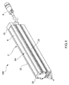
Fig. 1] Fig. 1 is a perspective view showing a line light irradiation device of the present embodiment. - [
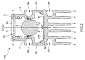
Fig. 2] Fig. 2 is a cross sectional view of the line light irradiation device of the same embodiment. - [
Fig. 3] Fig. 3 is a partially expanded sectional view showing details of a fixing mechanism of the same embodiment. - [
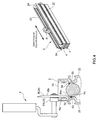
Fig. 4] Fig. 4 is a schematic diagram showing an inserting process of an elastic body of the same embodiment. - [
Fig. 5] Fig. 5 is a partially expanded sectional view of a line light irradiation device of a modified embodiment. - [
Fig. 6] Fig. 6 is a partially expanded sectional view of a line light irradiation device of a modified embodiment. - [
Fig. 7] Fig. 7 is a partially expanded sectional view of a line light irradiation device of a modified embodiment. -
- 1
- Line light irradiation device
- C
- Optical axis
- 2
- Casing
- 21
- Bottom wall part
- 22, 23
- Side wall part
- 3
- LED substrate
- 4
- Rod lens
- 5
- Fixing mechanism
- 51
- Projected rim part
- 51a
- Upward surface
- 51b
- Inward surface
- 52
- Notch portion
- 52a
- Downward surface
- 52b
- Outward surface
- 53
- Concave groove
- 54
- Elastic body
- Next, one embodiment of a line
light irradiation device 100 according to the present invention is described referring to drawings. - The line
light irradiation device 100 according to the present embodiment is adapted to irradiate line shaped light to, for example, a predetermined irradiation region of an inspection object (work) and it is used for such as a product inspection system etc. which photographs the predetermined irradiation region with a photographing device (not shown), captures obtained image data with an image processing device (not shown) to perform an automatic inspection of checking presence or absence of a defect such as, e.g., a crack or dirt, a foreign matter in liquid, or mark inspection. - Specifically, as shown in
Figs. 1 and2 , this device is provided with: acasing 2; aLED substrate 3 accommodated in thecasing 2; arod lens 4 which is a rod-like lens accommodated in thecasing 2; and afixing mechanism 5 for fixing therod lens 4 to thecasing 2. - As shown in
Fig. 2 , thecasing 2 is adapted to accommodate theLED substrate 3,rod lens 4 and alight transmission plate 6 such as a diffusion plate and a protection cover. Specifically, thecasing 2 is long sized metal one and is formed in a generally U-character shape in section perpendicularly intersecting in a longitudinal direction (extending direction), and includes abottom wall part 21 extending in the longitudinal direction and a pair of left and rightside wall parts bottom wall part 21. Thiscasing 2 is integrally formed one by extrusion molding or pultrusion molding, and on a back surface of thebottom wall part 21, there are provided plural sheets of radiator fins F along the longitudinal direction for radiating heat to the outside from theLED substrate 3. Further, in thebottom wall part 21, and left and rightside wall parts attachment grooves 2M for attaching the linelight irradiation device 100 to an external member (e.g., rack etc.). Further, front andrear side walls casing 2 with screws and the like. Thus, thecasing 2 is formed with a generally rectangular shaped lightoutgoing port 2H in the upper part thereof. In addition, anelectrical cable 8 is extended from therear side wall 25 for supplying electric power to the LED. - The
LED substrate 3 is a long sized substrate mounting a plurality ofLEDs 31. Specifically, theLED substrate 3 is formed by machine-mounting the plurality ofLEDs 31 to be arranged in one or more lines (one line inFig. 2 ) in a shorted side direction on a surface of a long sized print circuit board so as to align optical axes C1 thereof in a generally constant direction to be in a straight line state in a longer side direction. TheLEDs 31 are surface mount typed ones of arranging LED elements in a center of a package which forms, for example, a thin rectangular plate shape.Such LEDs 31 are arranged so as to arrange the LED elements, for example, at predetermined intervals in the longer side direction and shorter side direction, respectively. - This
LED substrate 3 is fixed to an upper surface of thebottom wall part 21 of thecasing 2. And regarding thisLED substrate 3, a longer sidedirection side surface 3a of theLED substrate 3 contacts with asubstrate contacting surface 211 which is a substrate positioning structure provided along the longitudinal direction on thebottom wall part 21, and theLED substrate 3 is thereby positioned to thecasing 2 in a lateral direction (a direction perpendicular to the longitudinal direction). - The
rod lens 4 is a condenser lens of a generally circular shape with an equal cross-section having a generally same length as a length of each of the left andright side walls casing 2. Thisrod lens 4 is provided along the longitudinal direction above theLED substrate 3 inside thecasing 2 and is fixed to be in a predetermined position with respect to the plurality ofLEDs 31 mounted on theLED substrate 3 by afixing mechanism 5 to be described later. Specifically, therod lens 4 is fixed by thefixing mechanism 5 in a manner such that an optical axis C2 of therod lens 4 coincides with the optical axes C1 of the plurality ofLEDs 31 and that therod lens 4 is spaced a predetermined distance with respect to the plurality ofLEDs 31. In addition, thelight transmission plate 6 such as a diffusion plate and a protection cover is provided in a front (upper portion) in a light outgoing side of therod lens 4, and since thislight transmission plate 6 is thermally expanded, it is attached by aslide groove 7 with a slight play formed in an inner surface of each of the left andright side walls - As shown in
Fig. 3 , thefixing mechanism 5 is intended to fix therod lens 4 to the pair of left and rightside wall parts casing 2, and it includes a projectedrim part 51 provided along the longitudinal direction in an inner surface of each of the left and rightside wall parts notch portions 52 provided along the longitudinal direction in side peripheral surfaces of therod lens 4, aconcave groove 53 provided along the longitudinal direction above the projectedrim part 51 in the inner surface of each of the left and rightside wall parts elastic body 54 detachably provided in each of theconcave grooves 53. - Especially, as shown in
Fig. 3 , each projectedrim part 51 is provided to be projected inward from the inner surface and extending over from one end to the other end in the longitudinal direction of each of the left and rightside wall parts upward surface 51a which is a generally horizontal plane and aninward surface 51b which is a plane generally perpendicular to theupward surface 51a. Further, the two projectedrim parts 51 provided in the respective left and rightside wall parts rim parts 51 in the pair of left and rightside wall parts rod lens 4 and configured to be able to accommodate therod lens 4 from an upper opening of thecasing 2. Thus, the accommodating work of therod lens 4 into thecasing 2 is facilitated. - Especially, as shown in
Fig. 3 , eachnotch potion 52 is formed to extend over from one end to the other end in the longitudinal direction in each of the side peripheral surfaces of therod lens 4, and it includes adownward surface 52a which is a plane contacting with theupward surface 51a of the projectedrim part 51 and anoutward surface 52b which is a plane generally perpendicular to thedownward surface 52a. The twonotch portions 52 formed in therod lens 4 have the same shape laterally symmetrical with respect to the optical axis C2. - And a distance between the
inward surfaces 51b of the two projectedrim parts 51 is generally identical to the distance between theoutward surfaces 52b of the twonotch portions 52, and theinward surfaces 51b of the projectedrim parts 51 are in contact with theoutward surfaces 52b of thenotch portions 52 in a state that theupward surfaces 51a of the projectedrim parts 51 are in contact with thedownward surfaces 52a of thenotch portions 52. Thus, therod lens 4 can be positioned with respect to thecasing 2 in the vertical direction as well as in the horizontal direction. That is, the optical axis C1 of eachLED 31 on theLED substrate 3 positioned in the lateral direction with respect to thecasing 2 coincides with the optical axis C2 of therod lens 4 positioned in the lateral direction with respect to thecasing 2. - The
concave groove 53 is provided along the longitudinal direction above the projectedrim part 51 to extend over from one end to the other end in the longitudinal direction in the inner surface of each of the left and rightside wall parts concave groove 53 is formed in a manner such that theelastic body 54 is fit thereto in a state that thedownward surface 52a of thenotch portion 52 is in contact with theupward surface 51a of the projectedrim part 51 and is formed in a position where theelastic body 54 contacts with the side peripheral surface of therod lens 4. - The
elastic body 54 is a linear tube having flexibility which is detachably provided in theconcave groove 53 and which is a silicon tube excellent in heat resistance and corrosion resistance in the present embodiment. This elastic body is fit to theconcave groove 53 in a state that thedownward surface 52a of thenotch portion 52 is in contact with theupward surface 51a of the projectedrim part 51 and is brought into contact with the side peripheral surface of the upper side portion above thenotch 52 in therod lens 4 to thereby press thenotch portion 52 to the projectedrim part 51. - Next, an assembling procedure of the line
light irradiation device 100 configured like this is described referring toFig. 4 . - First, after accommodating the
LED substrate 3 in thecasing 2 which has been pultrusion-molded or extrusion-molded and subjected to a prescribed process for fixing the front andrear side walls rod lens 4 is accommodated from, for example, an upper part opening of the casing 2 (lens accommodating process). In this state of accommodating therod lens 4 in the casing, thenotch portions 52 of therod lens 4 and the projectedrim parts 51 of thecasing 2 are brought into contact with each other, whereby therod lens 4 is vertically and laterally positioned with respect to thecasing 2. It is noted that, inFig. 4 , shown is a case where thefront side wall 24 is attached to the left andright side walls casing 2 in a step of accommodating theLED substrate 3 androd lens 4. - Then, the
silicon tubes 54 serving as the two elastic bodies are fit into the concave grooves of the left andright side walls 22 and 23 (elastic body fitting process). In this fitting work, after thesilicon tube 54 is arranged in a gap between the upper end portion of eachconcave groove 53 and the side peripheral surface of therod lens 4, thesilicon tube 54 is fitted into each of theconcave grooves 53 using a jig. - Here, the jig J includes a jig main body J1 having a tip surface which contacts with the
silicon tube 54 and a guide part J2 provided in the jig main body J1 and contacting with the upper surface of thecasing 2. Specifically, the jig main body J1 is a main body roller R rotatable about a rotation axis, and the guide part J2 is a guide roller R1 provided coaxially with the rotation axis of the main body roller R. The main body roller R has its one side surface Ra forming a plane shape and the other side surface Rb including a tapered surface Rb1. Further, the guide roller R1 contacts with the upper surface of thecasing 2, whereby a position of a side peripheral end surface Rc of the main body roller R is rendered to be a fitting position where thesilicon tube 54 is fit to theconcave groove 53. - Then, in a state that one of the side surface Ra of the main body roller R is along the inner side surface of the
casing 2, by rolling the guide roller R1 being in contact with the upper surface of thecasing 2, the side peripheral end surface Rc which is a tip surface of the main body roller R contacts with thesilicon tube 54 and thesilicon tube 54 is to be fit into theconcave groove 53 by pressing in thesilicon tube 54 from the upper portion. Further, since the other side surface Rb of the main body roller R has a tapered surface Rb1, the main body roller R does not contact with the side peripheral surface of therod lens 4 in the fitting process of thesilicon tube 54. Thus, thesilicon tube 54 is fit to theconcave groove 53, and thenotch portion 52 of therod lens 4 is pressed to be in a state of being fixed to the projectedrim part 51 of each of the left and rightside wall parts Fig. 3 ) between the upper end portion of theconcave groove 53 and the side peripheral surface of therod lens 4 is set to be smaller than the outer diameter of thesilicon tube 54 in a natural state (in a state of not being deformed by an external force). Thus, thesilicon tube 54 fit to theconcave groove 53 is prevented from being detached from theconcave groove 53. Here, the guide roller R1 is attached to the roller R, and by contacting this guide roller R1 with the upper surface of each of theside wall parts side wall parts silicon tube 54 into theconcave groove 53. - Moreover, in the assembling step, the
silicon tube 54 is partly rendered to protrude to a side of thefront side wall 25. And the protruded portion is pulled outward in the longitudinal direction and a proximal portion of the protruded portion is cut off. Thus, thesilicon tube 54 in theconcave groove 53 shrinks inward in the longitudinal direction and is rendered to be coplanar with the end surface of therod lens 4 or enter inside thereof. Thus, when therear side wall 25 is fixed to each of the left andright side walls silicon tube 54 is prevented from becoming an obstacle. - And after fitting the
silicon tube 54 to fix therod lens 4, thelight transmission plate 6 is slid to be attached to theslide groove 7, and thereafter therear side wall 25 is fixed to each of the left andright side walls light irradiation device 100. - According to the line
light irradiation device 100 according to the present embodiment configured like this, thefixing mechanism 5 includes the projectedrim part 51 provided in the inner surface of each of the left and rightside wall parts notch portion 52 provided in the side peripheral surface of therod lens 4, and by contacting between theseupward surface 51a and thedownward surface 52a, therod lens 4 can be fixed to thecasing 2 while positioning therod lens 4 to thecasing 2 in the vertical direction. - Further, since the
fixing mechanism 5 includes theconcave groove 53 and theelastic body 54 which is fitted to thisconcave groove 53 to press the side peripheral surface of therod lens 4, therod lens 4 can be fixed to thecasing 2 while preventing looseness of therod lens 4 to thecasing 2. - Furthermore, the contact between the
casing 2 and therod lens 4 is performed only between theupward surface 51a of the projectedrim part 51 and thedownward surface 52a of thenotch portion 52, and even though therod lens 4 is moved by sliding in the longitudinal direction, a light transmission portion of therod lens 4 is not damaged. - Moreover, after contacting the
downward surface 52a of thenotch portion 52 with theupward surface 51a of the projectedrim part 51, therod lens 4 can be fixed by pressing to thecasing 2 only by fitting theelastic body 54 to theconcave groove 53, and therefore the assembling work can be facilitated. At this time, since theelastic body 54 is not fitted to theconcave groove 53 at the time of attaching therod lens 4 to thecasing 2, the attachment work of therod lens 4 to thecasing 2 can be facilitated. - In addition, since the
casing 2 is integrally formed, not only the number of assembling man-hours can be reduced but also heat dissipation performance of thecasing 2 can be improved. Moreover, only thenotch portion 52 is provided in therod lens 4, and it is sufficient to merely process the rod lens such as cutting, and therefore the processing is easy and a manufacturing cost can also be lowered. - It is noted that the present invention is not limited to the above embodiment. For example, as shown in
Fig. 5 , the rod-like lens may be therod lens 4 having no notch portion. In this case, theupward surface 51a is provided in the inner surface of each of the left andright side walls rod lens 4. Also, thedownward surface 52a is formed of the side peripheral surface in the lower side of therod lens 4. - Further, as shown in
Fig. 6 , the rod-like lens may be a cylindrical lens having a semicircular shape in section. In this case, theupward surface 51a is formed of a generally horizontal upper surface of the projectedrim part 51 provided in the inner surface of each of the left andright side walls downward surface 52a is formed of each of the left and right end portions of the lower surface of thecylindrical lens 4. - Furthermore, as shown in
Fig. 7 , the rod-like lens 4 may have a projectedrim part 41 in each of left and right side portions along the longitudinal direction. In this case, theupward surface 51a is formed of a generally horizontal upper surface of the projectedrim part 51 provided in the inner surface of each of the left andright side walls downward surface 52a is formed of each of a generally horizontal lower surface of the projectedrim part 41 of the rod-like lens 4. Further, theinward surface 51b is formed of an upper part side surface of the projectedrim part 51 in each of the left andright side walls outward surface 52b is formed of a side surface in the lower part of the projectedrim part 41 in the rod-like lens 4. It is noted that this rof-like lens 4 has an equal shape in section in the longitudinal direction and aconcave portion 42 is opened for accommodating the LEDs. Abottom surface 42a of thisconcave portion 42 is formed to have a convex lens shape expanded toward the proximal side and aside surface 42b is substantially parallel to an optical axis. Meanwhile, a centralconvex lens part 43 is formed in a tip surface of thelens 4 by expanding the central portion thereof, and left and rightconvex lens part 44 of a different curvature therefrom are formed in both left and right sides of this centralconvex lens part 43. Further, in the side surface of thelens 4, there is provided a curved expandingsurface 45 that is a reflection element formed to have an outline in a parabola in section. - In addition, the present invention should not be limited to the above embodiments and it goes without saying that various modifications can be made. The invention is defined by appended claims only.
- By the present invention, a lens can be fixed to a casing and not only looseness thereof can be prevented but also an assembling work can be facilitated.
Claims (9)
- A line light irradiation device (100) comprising:an integrally molded casing (2) having a bottom wall part (21) extending in a longitudinal direction and a pair of side wall parts (22,23) extending upward from both sides in the longitudinal direction of the bottom wall part (21);a LED substrate (3) provided on the bottom wall part (21) of the casing (1);a rod-shaped lens (4) provided above the LED substrate (3) along the longitudinal direction inside the casing (1); anda fixing mechanism (5) for fixing the lens (4) to the pair of side wall parts (22,23),wherein the fixing mechanism (5) comprises:an upward surface (51a) provided along the longitudinal direction in an inner surface of each of the side wall parts (22,23);a downward surface (52a) provided along the longitudinal direction in each side peripheral surface of the lens (4);a concave groove (53) provided along the longitudinal direction above the upward surface (51a) in the inner surface of each of the side wall parts (22,23); andan elastic body (54) detachably provided in the concave groove (53) and fitting into the concave groove (53) to be in contact with the side peripheral surface of the lens (4) in a state that the downward surface (52a) is in contact with the upward surface (51a) to thereby press the downward surface (52a) to the upward surface (51a),characterized in that the line light irradiation device (100) is configured so that the elastic body (54) is fit into the concave groove (53) by pressing in the elastic body (54) from an upper opening of the casing (2).
- The line light irradiation device (100) according to claim 1, wherein the shortest distance between an upper end portion of the concave groove (53) and the side peripheral surface of the lens (4) is smaller than a width size in a natural state of the elastic body (54).
- The line light irradiation device (100) according to claim 1, wherein the upward surface (51a) is formed of an upper surface of a projected rim part (51) provided along the longitudinal direction in the inner surface of each of the side wall parts (22,23), and
the downward surface (52a) is formed of a lower surface of each of two notch portions (52) which are provided along the side peripheral surface of the lens (4) and symmetrically formed with respect to an optical axis (C). - The line light irradiation device (100) according to claim 3, wherein the projected rim part (51) has an inward surface (51b) which is substantially perpendicular to the upward surface (51a),
the notch portion (52) has an outward surface (52b) which is substantially perpendicular to the downward surface (52a), and
the upward surface (51a) of the projected rim part (51) is in contact with the downward surface (52a) of the notch portion (52) in a state that the inward surface (51b) of the projected rim part (51) is in contact with the outward surface(52b) of the notch portion (52). - The line light irradiation device (100) according to claim 3, wherein a space between upper side portions above the projected rim parts (51) of the pair of side wall parts (22,23) is configured to be larger than an outer diameter of the lens (4).
- A manufacturing method of the line light irradiation device (100) according to claim 1 comprising:a lens accommodation process of accommodating the lens (4) in the casing (2); andan elastic body fitting process of fitting the elastic body (54) into the concave groove (53) by pressing in the elastic body (54) from the upper opening of the casing (2) after the lens accommodation process.
- The manufacturing method according to claim 6, wherein the elastic body fitting process fits the elastic body (54) into the concave groove (53) using a jig after the elastic body fitting process arranges the elastic body (54) in a gap between the upper end portion of the concave portion (53) and the side surface of the lens (4).
- The manufacturing method according to claim 7, wherein the jig (J) includes a jig main body (J1) having a tip surface which is in contact with the elastic body (54), and a guide part (J2) which is provided in the jig main body (J1) and to be in contact with an upper surface of the casing (2), and
by bringing the guide part (J2) into contact with the upper surface of the casing (2), the tip surface of the jig main body (J1) is in contact with the elastic body (54) to thereby fit the elastic body (54) into the concave groove (53). - The manufacturing method according to claim 8, wherein the jig main body (J1) is a main body roller (R) which is rotatable about a rotation axis,
the guide part (J2) is a guide roller R1) coaxially provided with the rotation axis of the main body roller (R);
by rolling the guide roller (R1) while contacting with the upper surface of the casing (2) in a state that one side surface of the main body roller (R) is along an inner side surface of the casing (2), a side peripheral end surface of the main body roller (R) is in contact with the elastic body (54) to thereby fit the elastic body (54) into the concave groove (53).
Applications Claiming Priority (2)
| Application Number | Priority Date | Filing Date | Title |
|---|---|---|---|
| JP2011048237A JP5322014B2 (en) | 2011-03-04 | 2011-03-04 | Line light irradiation apparatus and manufacturing method |
| PCT/JP2012/053664 WO2012120987A1 (en) | 2011-03-04 | 2012-02-16 | Linear light irradiation device and method for producing same |
Publications (3)
| Publication Number | Publication Date |
|---|---|
| EP2682669A1 EP2682669A1 (en) | 2014-01-08 |
| EP2682669A4 EP2682669A4 (en) | 2014-09-17 |
| EP2682669B1 true EP2682669B1 (en) | 2016-04-27 |
Family
ID=46797956
Family Applications (1)
| Application Number | Title | Priority Date | Filing Date |
|---|---|---|---|
| EP12755151.3A Not-in-force EP2682669B1 (en) | 2011-03-04 | 2012-02-16 | Linear light irradiation device and method for producing same |
Country Status (6)
| Country | Link |
|---|---|
| US (1) | US9022597B2 (en) |
| EP (1) | EP2682669B1 (en) |
| JP (1) | JP5322014B2 (en) |
| KR (1) | KR101483896B1 (en) |
| CA (1) | CA2821704C (en) |
| WO (1) | WO2012120987A1 (en) |
Families Citing this family (14)
| Publication number | Priority date | Publication date | Assignee | Title |
|---|---|---|---|---|
| JP2014122799A (en) * | 2012-12-20 | 2014-07-03 | Ccs Inc | Line light radiation device |
| CN103557498B (en) * | 2013-11-12 | 2015-10-21 | 深圳雷曼光电科技股份有限公司 | Light source fixed support and adopt the support bracket fastened light fixture of this light source |
| US9527437B2 (en) * | 2015-01-26 | 2016-12-27 | The Boeing Company | Lighting assembly for interior cabin of a vehicle |
| JP6580511B2 (en) * | 2015-04-07 | 2019-09-25 | レボックス株式会社 | Lighting device |
| EP3273150B1 (en) * | 2016-07-20 | 2019-11-06 | Festool GmbH | Control lamp, illumination device and method of controlling surface structures |
| GB2554418A (en) * | 2016-09-26 | 2018-04-04 | Bee Lighting Ltd | Lighting unit |
| JP6914091B2 (en) * | 2017-04-25 | 2021-08-04 | 三菱電機株式会社 | Light source device and lighting device |
| EP3473926B1 (en) | 2017-10-23 | 2020-04-08 | Glashütte Limburg Leuchten GmbH + Co. KG | Lighting apparatus and method for attachment of two parts thereof |
| CN108758558A (en) * | 2018-06-07 | 2018-11-06 | 厦门普为光电科技有限公司 | The lampshade of lighting angle can be concentrated |
| US10865976B2 (en) * | 2019-04-02 | 2020-12-15 | Delta Electronics, Inc. | Light-emitting diode driver with wireless device function |
| JP2023173165A (en) * | 2022-05-25 | 2023-12-07 | 株式会社リコー | Lighting device and image reading device |
| US11898729B2 (en) * | 2022-06-09 | 2024-02-13 | Leedarson Lighting Co., Ltd. | Lighting apparatus |
| KR102834220B1 (en) * | 2023-05-23 | 2025-07-14 | 박병기 | Lighting Device |
| USD1101244S1 (en) * | 2024-03-19 | 2025-11-04 | Ip Llc A Series Of Moda Light Llc | Exterior light fixture |
Family Cites Families (9)
| Publication number | Priority date | Publication date | Assignee | Title |
|---|---|---|---|---|
| JPH01280571A (en) * | 1988-05-06 | 1989-11-10 | Oki Electric Ind Co Ltd | Optical printing head |
| JPH01311759A (en) * | 1988-06-10 | 1989-12-15 | Fuji Photo Film Co Ltd | Original lighting device |
| JPH06135052A (en) * | 1992-10-26 | 1994-05-17 | Sanyo Electric Co Ltd | Optical print head |
| JPH1172734A (en) * | 1997-08-29 | 1999-03-16 | Ricoh Co Ltd | Light beam scanning device |
| JP2000252664A (en) | 1999-03-04 | 2000-09-14 | Accuphase Laboratory Inc | Printed wiring board |
| DE60140161D1 (en) | 2000-08-22 | 2009-11-26 | Koninkl Philips Electronics Nv | Luminaire based on LED light emission supported |
| DE102006009444A1 (en) | 2006-03-01 | 2007-09-13 | Texmag Gmbh Vertriebsgesellschaft Gmbh | Device for emission of linear light |
| US7300179B1 (en) * | 2007-01-04 | 2007-11-27 | Disney Enterprises, Inc. | Light sheet display using light strips with adjustable positions and orientations |
| JP2010112939A (en) | 2008-11-05 | 2010-05-20 | Tozai Denko Co Ltd | Light source device |
-
2011
- 2011-03-04 JP JP2011048237A patent/JP5322014B2/en active Active
-
2012
- 2012-02-16 KR KR1020137015418A patent/KR101483896B1/en not_active Expired - Fee Related
- 2012-02-16 CA CA2821704A patent/CA2821704C/en active Active
- 2012-02-16 WO PCT/JP2012/053664 patent/WO2012120987A1/en not_active Ceased
- 2012-02-16 EP EP12755151.3A patent/EP2682669B1/en not_active Not-in-force
- 2012-02-16 US US13/978,522 patent/US9022597B2/en active Active
Also Published As
| Publication number | Publication date |
|---|---|
| CA2821704A1 (en) | 2012-09-13 |
| CA2821704C (en) | 2015-09-08 |
| EP2682669A4 (en) | 2014-09-17 |
| WO2012120987A1 (en) | 2012-09-13 |
| US9022597B2 (en) | 2015-05-05 |
| US20130329436A1 (en) | 2013-12-12 |
| JP5322014B2 (en) | 2013-10-23 |
| KR20130110195A (en) | 2013-10-08 |
| EP2682669A1 (en) | 2014-01-08 |
| KR101483896B1 (en) | 2015-01-16 |
| JP2012186014A (en) | 2012-09-27 |
Similar Documents
| Publication | Publication Date | Title |
|---|---|---|
| CA2821704C (en) | Line light irradiation device and manufacturing method thereof | |
| EP2682670A1 (en) | Linear light irradiation device | |
| US8436375B2 (en) | Light illuminating device | |
| US8342734B2 (en) | Vehicular light source unit | |
| EP0853356A2 (en) | A connector producing method and a connector produced by insert molding and a use thereof | |
| JP6289746B2 (en) | Vehicle headlamp | |
| CN101153689A (en) | Circular lighting device and its manufacturing method | |
| WO2015104679A1 (en) | Connector | |
| JPWO2012133568A1 (en) | Optical fiber coating removal tool and coating removal method | |
| WO2012066796A1 (en) | Illumination device, and illumination system provided with multiple illumination devices | |
| US20110021045A1 (en) | Electrical connector with light pipe | |
| JP6021619B2 (en) | Optical connector, optical connector system, optical backplane device | |
| JP2017150875A (en) | Line light irradiation device | |
| EP1544951B1 (en) | Electrical connector | |
| FR2884036A1 (en) | TOOLS FOR THE MANUFACTURE OF LARGE SECTIONS RIGID HARNESSES | |
| US9477055B1 (en) | Optical module and fixing apparatus thereof | |
| TWI384695B (en) | Electrical connector | |
| US20080124984A1 (en) | LED Lamp Holder | |
| US20060092654A1 (en) | Vehicle light | |
| JP2000323860A (en) | Electronic device unit | |
| KR101108904B1 (en) | connector | |
| JP2024026197A (en) | lighting equipment | |
| JP2023000454A (en) | LED lighting device | |
| JP5007392B2 (en) | LED and light guide plate positioning structure and light irradiation device | |
| JP5981649B2 (en) | Cable forming jig and press connection method of flat cable |
Legal Events
| Date | Code | Title | Description |
|---|---|---|---|
| PUAI | Public reference made under article 153(3) epc to a published international application that has entered the european phase |
Free format text: ORIGINAL CODE: 0009012 |
|
| 17P | Request for examination filed |
Effective date: 20130625 |
|
| AK | Designated contracting states |
Kind code of ref document: A1 Designated state(s): AL AT BE BG CH CY CZ DE DK EE ES FI FR GB GR HR HU IE IS IT LI LT LU LV MC MK MT NL NO PL PT RO RS SE SI SK SM TR |
|
| DAX | Request for extension of the european patent (deleted) | ||
| A4 | Supplementary search report drawn up and despatched |
Effective date: 20140819 |
|
| RIC1 | Information provided on ipc code assigned before grant |
Ipc: F21Y 101/02 20060101ALI20140812BHEP Ipc: F21S 2/00 20060101AFI20140812BHEP Ipc: F21V 29/00 20060101ALI20140812BHEP Ipc: F21V 5/04 20060101ALI20140812BHEP Ipc: F21V 8/00 20060101ALI20140812BHEP |
|
| 17Q | First examination report despatched |
Effective date: 20150319 |
|
| GRAP | Despatch of communication of intention to grant a patent |
Free format text: ORIGINAL CODE: EPIDOSNIGR1 |
|
| INTG | Intention to grant announced |
Effective date: 20151112 |
|
| RIC1 | Information provided on ipc code assigned before grant |
Ipc: F21Y 101/02 20060101ALI20151102BHEP Ipc: F21V 17/16 20060101ALI20151102BHEP Ipc: G01N 21/88 20060101ALI20151102BHEP Ipc: F21V 8/00 20060101ALI20151102BHEP Ipc: F21V 5/04 20060101ALI20151102BHEP Ipc: F21S 4/00 20060101AFI20151102BHEP Ipc: F21V 29/00 20150101ALI20151102BHEP Ipc: F21S 2/00 20060101ALI20151102BHEP Ipc: F21V 15/01 20060101ALI20151102BHEP |
|
| GRAS | Grant fee paid |
Free format text: ORIGINAL CODE: EPIDOSNIGR3 |
|
| REG | Reference to a national code |
Ref country code: DE Ref legal event code: R079 Ref document number: 602012017758 Country of ref document: DE Free format text: PREVIOUS MAIN CLASS: F21S0002000000 Ipc: F21S0004000000 |
|
| GRAA | (expected) grant |
Free format text: ORIGINAL CODE: 0009210 |
|
| RIC1 | Information provided on ipc code assigned before grant |
Ipc: F21V 5/04 20060101ALI20160316BHEP Ipc: F21S 2/00 20160101ALI20160316BHEP Ipc: F21S 4/00 20160101AFI20160316BHEP Ipc: F21V 29/00 20150101ALI20160316BHEP Ipc: F21V 17/16 20060101ALI20160316BHEP Ipc: F21V 8/00 20060101ALI20160316BHEP Ipc: F21V 15/01 20060101ALI20160316BHEP Ipc: G01N 21/88 20060101ALI20160316BHEP Ipc: F21Y 115/10 20160101ALI20160316BHEP |
|
| AK | Designated contracting states |
Kind code of ref document: B1 Designated state(s): AL AT BE BG CH CY CZ DE DK EE ES FI FR GB GR HR HU IE IS IT LI LT LU LV MC MK MT NL NO PL PT RO RS SE SI SK SM TR |
|
| REG | Reference to a national code |
Ref country code: GB Ref legal event code: FG4D |
|
| REG | Reference to a national code |
Ref country code: CH Ref legal event code: EP |
|
| REG | Reference to a national code |
Ref country code: AT Ref legal event code: REF Ref document number: 795224 Country of ref document: AT Kind code of ref document: T Effective date: 20160515 |
|
| REG | Reference to a national code |
Ref country code: IE Ref legal event code: FG4D |
|
| REG | Reference to a national code |
Ref country code: DE Ref legal event code: R096 Ref document number: 602012017758 Country of ref document: DE |
|
| REG | Reference to a national code |
Ref country code: LT Ref legal event code: MG4D |
|
| REG | Reference to a national code |
Ref country code: NL Ref legal event code: MP Effective date: 20160427 |
|
| REG | Reference to a national code |
Ref country code: AT Ref legal event code: MK05 Ref document number: 795224 Country of ref document: AT Kind code of ref document: T Effective date: 20160427 |
|
| PG25 | Lapsed in a contracting state [announced via postgrant information from national office to epo] |
Ref country code: NL Free format text: LAPSE BECAUSE OF FAILURE TO SUBMIT A TRANSLATION OF THE DESCRIPTION OR TO PAY THE FEE WITHIN THE PRESCRIBED TIME-LIMIT Effective date: 20160427 |
|
| PG25 | Lapsed in a contracting state [announced via postgrant information from national office to epo] |
Ref country code: FI Free format text: LAPSE BECAUSE OF FAILURE TO SUBMIT A TRANSLATION OF THE DESCRIPTION OR TO PAY THE FEE WITHIN THE PRESCRIBED TIME-LIMIT Effective date: 20160427 Ref country code: PL Free format text: LAPSE BECAUSE OF FAILURE TO SUBMIT A TRANSLATION OF THE DESCRIPTION OR TO PAY THE FEE WITHIN THE PRESCRIBED TIME-LIMIT Effective date: 20160427 Ref country code: LT Free format text: LAPSE BECAUSE OF FAILURE TO SUBMIT A TRANSLATION OF THE DESCRIPTION OR TO PAY THE FEE WITHIN THE PRESCRIBED TIME-LIMIT Effective date: 20160427 Ref country code: NO Free format text: LAPSE BECAUSE OF FAILURE TO SUBMIT A TRANSLATION OF THE DESCRIPTION OR TO PAY THE FEE WITHIN THE PRESCRIBED TIME-LIMIT Effective date: 20160727 |
|
| PG25 | Lapsed in a contracting state [announced via postgrant information from national office to epo] |
Ref country code: RS Free format text: LAPSE BECAUSE OF FAILURE TO SUBMIT A TRANSLATION OF THE DESCRIPTION OR TO PAY THE FEE WITHIN THE PRESCRIBED TIME-LIMIT Effective date: 20160427 Ref country code: AT Free format text: LAPSE BECAUSE OF FAILURE TO SUBMIT A TRANSLATION OF THE DESCRIPTION OR TO PAY THE FEE WITHIN THE PRESCRIBED TIME-LIMIT Effective date: 20160427 Ref country code: GR Free format text: LAPSE BECAUSE OF FAILURE TO SUBMIT A TRANSLATION OF THE DESCRIPTION OR TO PAY THE FEE WITHIN THE PRESCRIBED TIME-LIMIT Effective date: 20160728 Ref country code: SE Free format text: LAPSE BECAUSE OF FAILURE TO SUBMIT A TRANSLATION OF THE DESCRIPTION OR TO PAY THE FEE WITHIN THE PRESCRIBED TIME-LIMIT Effective date: 20160427 Ref country code: PT Free format text: LAPSE BECAUSE OF FAILURE TO SUBMIT A TRANSLATION OF THE DESCRIPTION OR TO PAY THE FEE WITHIN THE PRESCRIBED TIME-LIMIT Effective date: 20160829 Ref country code: ES Free format text: LAPSE BECAUSE OF FAILURE TO SUBMIT A TRANSLATION OF THE DESCRIPTION OR TO PAY THE FEE WITHIN THE PRESCRIBED TIME-LIMIT Effective date: 20160427 Ref country code: LV Free format text: LAPSE BECAUSE OF FAILURE TO SUBMIT A TRANSLATION OF THE DESCRIPTION OR TO PAY THE FEE WITHIN THE PRESCRIBED TIME-LIMIT Effective date: 20160427 Ref country code: HR Free format text: LAPSE BECAUSE OF FAILURE TO SUBMIT A TRANSLATION OF THE DESCRIPTION OR TO PAY THE FEE WITHIN THE PRESCRIBED TIME-LIMIT Effective date: 20160427 |
|
| PG25 | Lapsed in a contracting state [announced via postgrant information from national office to epo] |
Ref country code: IT Free format text: LAPSE BECAUSE OF FAILURE TO SUBMIT A TRANSLATION OF THE DESCRIPTION OR TO PAY THE FEE WITHIN THE PRESCRIBED TIME-LIMIT Effective date: 20160427 Ref country code: BE Free format text: LAPSE BECAUSE OF FAILURE TO SUBMIT A TRANSLATION OF THE DESCRIPTION OR TO PAY THE FEE WITHIN THE PRESCRIBED TIME-LIMIT Effective date: 20160427 |
|
| REG | Reference to a national code |
Ref country code: DE Ref legal event code: R097 Ref document number: 602012017758 Country of ref document: DE |
|
| PG25 | Lapsed in a contracting state [announced via postgrant information from national office to epo] |
Ref country code: RO Free format text: LAPSE BECAUSE OF FAILURE TO SUBMIT A TRANSLATION OF THE DESCRIPTION OR TO PAY THE FEE WITHIN THE PRESCRIBED TIME-LIMIT Effective date: 20160427 Ref country code: EE Free format text: LAPSE BECAUSE OF FAILURE TO SUBMIT A TRANSLATION OF THE DESCRIPTION OR TO PAY THE FEE WITHIN THE PRESCRIBED TIME-LIMIT Effective date: 20160427 Ref country code: DK Free format text: LAPSE BECAUSE OF FAILURE TO SUBMIT A TRANSLATION OF THE DESCRIPTION OR TO PAY THE FEE WITHIN THE PRESCRIBED TIME-LIMIT Effective date: 20160427 Ref country code: SK Free format text: LAPSE BECAUSE OF FAILURE TO SUBMIT A TRANSLATION OF THE DESCRIPTION OR TO PAY THE FEE WITHIN THE PRESCRIBED TIME-LIMIT Effective date: 20160427 Ref country code: CZ Free format text: LAPSE BECAUSE OF FAILURE TO SUBMIT A TRANSLATION OF THE DESCRIPTION OR TO PAY THE FEE WITHIN THE PRESCRIBED TIME-LIMIT Effective date: 20160427 |
|
| REG | Reference to a national code |
Ref country code: FR Ref legal event code: PLFP Year of fee payment: 6 |
|
| PG25 | Lapsed in a contracting state [announced via postgrant information from national office to epo] |
Ref country code: SM Free format text: LAPSE BECAUSE OF FAILURE TO SUBMIT A TRANSLATION OF THE DESCRIPTION OR TO PAY THE FEE WITHIN THE PRESCRIBED TIME-LIMIT Effective date: 20160427 |
|
| PLBE | No opposition filed within time limit |
Free format text: ORIGINAL CODE: 0009261 |
|
| STAA | Information on the status of an ep patent application or granted ep patent |
Free format text: STATUS: NO OPPOSITION FILED WITHIN TIME LIMIT |
|
| 26N | No opposition filed |
Effective date: 20170130 |
|
| PG25 | Lapsed in a contracting state [announced via postgrant information from national office to epo] |
Ref country code: SI Free format text: LAPSE BECAUSE OF FAILURE TO SUBMIT A TRANSLATION OF THE DESCRIPTION OR TO PAY THE FEE WITHIN THE PRESCRIBED TIME-LIMIT Effective date: 20160427 |
|
| PG25 | Lapsed in a contracting state [announced via postgrant information from national office to epo] |
Ref country code: MC Free format text: LAPSE BECAUSE OF FAILURE TO SUBMIT A TRANSLATION OF THE DESCRIPTION OR TO PAY THE FEE WITHIN THE PRESCRIBED TIME-LIMIT Effective date: 20160427 |
|
| REG | Reference to a national code |
Ref country code: CH Ref legal event code: PL |
|
| PG25 | Lapsed in a contracting state [announced via postgrant information from national office to epo] |
Ref country code: CH Free format text: LAPSE BECAUSE OF NON-PAYMENT OF DUE FEES Effective date: 20170228 Ref country code: LI Free format text: LAPSE BECAUSE OF NON-PAYMENT OF DUE FEES Effective date: 20170228 |
|
| REG | Reference to a national code |
Ref country code: IE Ref legal event code: MM4A |
|
| PG25 | Lapsed in a contracting state [announced via postgrant information from national office to epo] |
Ref country code: LU Free format text: LAPSE BECAUSE OF NON-PAYMENT OF DUE FEES Effective date: 20170216 |
|
| REG | Reference to a national code |
Ref country code: FR Ref legal event code: PLFP Year of fee payment: 7 |
|
| PG25 | Lapsed in a contracting state [announced via postgrant information from national office to epo] |
Ref country code: IE Free format text: LAPSE BECAUSE OF NON-PAYMENT OF DUE FEES Effective date: 20170216 |
|
| PG25 | Lapsed in a contracting state [announced via postgrant information from national office to epo] |
Ref country code: MT Free format text: LAPSE BECAUSE OF NON-PAYMENT OF DUE FEES Effective date: 20170216 |
|
| PG25 | Lapsed in a contracting state [announced via postgrant information from national office to epo] |
Ref country code: AL Free format text: LAPSE BECAUSE OF FAILURE TO SUBMIT A TRANSLATION OF THE DESCRIPTION OR TO PAY THE FEE WITHIN THE PRESCRIBED TIME-LIMIT Effective date: 20160427 |
|
| PG25 | Lapsed in a contracting state [announced via postgrant information from national office to epo] |
Ref country code: HU Free format text: LAPSE BECAUSE OF FAILURE TO SUBMIT A TRANSLATION OF THE DESCRIPTION OR TO PAY THE FEE WITHIN THE PRESCRIBED TIME-LIMIT; INVALID AB INITIO Effective date: 20120216 |
|
| PG25 | Lapsed in a contracting state [announced via postgrant information from national office to epo] |
Ref country code: BG Free format text: LAPSE BECAUSE OF FAILURE TO SUBMIT A TRANSLATION OF THE DESCRIPTION OR TO PAY THE FEE WITHIN THE PRESCRIBED TIME-LIMIT Effective date: 20160427 |
|
| PG25 | Lapsed in a contracting state [announced via postgrant information from national office to epo] |
Ref country code: CY Free format text: LAPSE BECAUSE OF NON-PAYMENT OF DUE FEES Effective date: 20160427 |
|
| PG25 | Lapsed in a contracting state [announced via postgrant information from national office to epo] |
Ref country code: MK Free format text: LAPSE BECAUSE OF FAILURE TO SUBMIT A TRANSLATION OF THE DESCRIPTION OR TO PAY THE FEE WITHIN THE PRESCRIBED TIME-LIMIT Effective date: 20160427 |
|
| PG25 | Lapsed in a contracting state [announced via postgrant information from national office to epo] |
Ref country code: TR Free format text: LAPSE BECAUSE OF FAILURE TO SUBMIT A TRANSLATION OF THE DESCRIPTION OR TO PAY THE FEE WITHIN THE PRESCRIBED TIME-LIMIT Effective date: 20160427 |
|
| PG25 | Lapsed in a contracting state [announced via postgrant information from national office to epo] |
Ref country code: IS Free format text: LAPSE BECAUSE OF FAILURE TO SUBMIT A TRANSLATION OF THE DESCRIPTION OR TO PAY THE FEE WITHIN THE PRESCRIBED TIME-LIMIT Effective date: 20160827 |
|
| PGFP | Annual fee paid to national office [announced via postgrant information from national office to epo] |
Ref country code: FR Payment date: 20230217 Year of fee payment: 12 |
|
| PGFP | Annual fee paid to national office [announced via postgrant information from national office to epo] |
Ref country code: GB Payment date: 20230221 Year of fee payment: 12 Ref country code: DE Payment date: 20221212 Year of fee payment: 12 |
|
| REG | Reference to a national code |
Ref country code: DE Ref legal event code: R119 Ref document number: 602012017758 Country of ref document: DE |
|
| GBPC | Gb: european patent ceased through non-payment of renewal fee |
Effective date: 20240216 |
|
| PG25 | Lapsed in a contracting state [announced via postgrant information from national office to epo] |
Ref country code: DE Free format text: LAPSE BECAUSE OF NON-PAYMENT OF DUE FEES Effective date: 20240903 |
|
| PG25 | Lapsed in a contracting state [announced via postgrant information from national office to epo] |
Ref country code: GB Free format text: LAPSE BECAUSE OF NON-PAYMENT OF DUE FEES Effective date: 20240216 |
|
| PG25 | Lapsed in a contracting state [announced via postgrant information from national office to epo] |
Ref country code: FR Free format text: LAPSE BECAUSE OF NON-PAYMENT OF DUE FEES Effective date: 20240229 |
|
| PG25 | Lapsed in a contracting state [announced via postgrant information from national office to epo] |
Ref country code: GB Free format text: LAPSE BECAUSE OF NON-PAYMENT OF DUE FEES Effective date: 20240216 Ref country code: FR Free format text: LAPSE BECAUSE OF NON-PAYMENT OF DUE FEES Effective date: 20240229 Ref country code: DE Free format text: LAPSE BECAUSE OF NON-PAYMENT OF DUE FEES Effective date: 20240903 |