EP2682668A2 - Device for supplying gas under pressure and installation for producing and supplying electricity comprising such a device - Google Patents
Device for supplying gas under pressure and installation for producing and supplying electricity comprising such a device Download PDFInfo
- Publication number
- EP2682668A2 EP2682668A2 EP12179807.8A EP12179807A EP2682668A2 EP 2682668 A2 EP2682668 A2 EP 2682668A2 EP 12179807 A EP12179807 A EP 12179807A EP 2682668 A2 EP2682668 A2 EP 2682668A2
- Authority
- EP
- European Patent Office
- Prior art keywords
- rack
- gas
- cylinders
- connector
- sheath
- Prior art date
- Legal status (The legal status is an assumption and is not a legal conclusion. Google has not performed a legal analysis and makes no representation as to the accuracy of the status listed.)
- Withdrawn
Links
- 238000009434 installation Methods 0.000 title claims description 41
- 230000005611 electricity Effects 0.000 title claims description 5
- 238000011144 upstream manufacturing Methods 0.000 claims abstract description 21
- 230000001681 protective effect Effects 0.000 claims abstract description 13
- 239000007789 gas Substances 0.000 claims description 89
- UFHFLCQGNIYNRP-UHFFFAOYSA-N Hydrogen Chemical compound [H][H] UFHFLCQGNIYNRP-UHFFFAOYSA-N 0.000 claims description 18
- 239000000446 fuel Substances 0.000 claims description 18
- 239000001257 hydrogen Substances 0.000 claims description 16
- 229910052739 hydrogen Inorganic materials 0.000 claims description 16
- 230000000452 restraining effect Effects 0.000 claims description 16
- 230000006978 adaptation Effects 0.000 claims description 6
- 238000010926 purge Methods 0.000 claims description 5
- 239000012530 fluid Substances 0.000 claims description 3
- 230000005540 biological transmission Effects 0.000 claims description 2
- 150000002431 hydrogen Chemical class 0.000 claims description 2
- 239000012528 membrane Substances 0.000 claims description 2
- 230000036961 partial effect Effects 0.000 description 9
- 230000001276 controlling effect Effects 0.000 description 8
- 238000004378 air conditioning Methods 0.000 description 4
- 239000002184 metal Substances 0.000 description 4
- 230000016571 aggressive behavior Effects 0.000 description 3
- 238000012423 maintenance Methods 0.000 description 3
- 210000003739 neck Anatomy 0.000 description 3
- 238000000034 method Methods 0.000 description 2
- 239000000047 product Substances 0.000 description 2
- 238000009825 accumulation Methods 0.000 description 1
- 238000005452 bending Methods 0.000 description 1
- 230000000903 blocking effect Effects 0.000 description 1
- 230000000295 complement effect Effects 0.000 description 1
- 239000002131 composite material Substances 0.000 description 1
- 230000003750 conditioning effect Effects 0.000 description 1
- 230000006378 damage Effects 0.000 description 1
- 238000007599 discharging Methods 0.000 description 1
- 230000000694 effects Effects 0.000 description 1
- 239000002828 fuel tank Substances 0.000 description 1
- 230000001590 oxidative effect Effects 0.000 description 1
- 238000004806 packaging method and process Methods 0.000 description 1
- 238000005192 partition Methods 0.000 description 1
- 230000002093 peripheral effect Effects 0.000 description 1
- 229920000642 polymer Polymers 0.000 description 1
- 230000002829 reductive effect Effects 0.000 description 1
- 230000001105 regulatory effect Effects 0.000 description 1
- 230000000717 retained effect Effects 0.000 description 1
- 238000012502 risk assessment Methods 0.000 description 1
- 239000007787 solid Substances 0.000 description 1
- 239000013589 supplement Substances 0.000 description 1
- 231100000331 toxic Toxicity 0.000 description 1
- 230000002588 toxic effect Effects 0.000 description 1
Images


Classifications
-
- H—ELECTRICITY
- H01—ELECTRIC ELEMENTS
- H01M—PROCESSES OR MEANS, e.g. BATTERIES, FOR THE DIRECT CONVERSION OF CHEMICAL ENERGY INTO ELECTRICAL ENERGY
- H01M8/00—Fuel cells; Manufacture thereof
- H01M8/04—Auxiliary arrangements, e.g. for control of pressure or for circulation of fluids
- H01M8/04082—Arrangements for control of reactant parameters, e.g. pressure or concentration
- H01M8/04201—Reactant storage and supply, e.g. means for feeding, pipes
-
- F—MECHANICAL ENGINEERING; LIGHTING; HEATING; WEAPONS; BLASTING
- F17—STORING OR DISTRIBUTING GASES OR LIQUIDS
- F17C—VESSELS FOR CONTAINING OR STORING COMPRESSED, LIQUEFIED OR SOLIDIFIED GASES; FIXED-CAPACITY GAS-HOLDERS; FILLING VESSELS WITH, OR DISCHARGING FROM VESSELS, COMPRESSED, LIQUEFIED, OR SOLIDIFIED GASES
- F17C13/00—Details of vessels or of the filling or discharging of vessels
- F17C13/04—Arrangement or mounting of valves
- F17C13/045—Automatic change-over switching assembly for bottled gas systems with two (or more) gas containers
-
- F—MECHANICAL ENGINEERING; LIGHTING; HEATING; WEAPONS; BLASTING
- F17—STORING OR DISTRIBUTING GASES OR LIQUIDS
- F17C—VESSELS FOR CONTAINING OR STORING COMPRESSED, LIQUEFIED OR SOLIDIFIED GASES; FIXED-CAPACITY GAS-HOLDERS; FILLING VESSELS WITH, OR DISCHARGING FROM VESSELS, COMPRESSED, LIQUEFIED, OR SOLIDIFIED GASES
- F17C13/00—Details of vessels or of the filling or discharging of vessels
- F17C13/08—Mounting arrangements for vessels
- F17C13/084—Mounting arrangements for vessels for small-sized storage vessels, e.g. compressed gas cylinders or bottles, disposable gas vessels, vessels adapted for automotive use
-
- F—MECHANICAL ENGINEERING; LIGHTING; HEATING; WEAPONS; BLASTING
- F17—STORING OR DISTRIBUTING GASES OR LIQUIDS
- F17C—VESSELS FOR CONTAINING OR STORING COMPRESSED, LIQUEFIED OR SOLIDIFIED GASES; FIXED-CAPACITY GAS-HOLDERS; FILLING VESSELS WITH, OR DISCHARGING FROM VESSELS, COMPRESSED, LIQUEFIED, OR SOLIDIFIED GASES
- F17C5/00—Methods or apparatus for filling containers with liquefied, solidified, or compressed gases under pressures
- F17C5/06—Methods or apparatus for filling containers with liquefied, solidified, or compressed gases under pressures for filling with compressed gases
-
- F—MECHANICAL ENGINEERING; LIGHTING; HEATING; WEAPONS; BLASTING
- F17—STORING OR DISTRIBUTING GASES OR LIQUIDS
- F17C—VESSELS FOR CONTAINING OR STORING COMPRESSED, LIQUEFIED OR SOLIDIFIED GASES; FIXED-CAPACITY GAS-HOLDERS; FILLING VESSELS WITH, OR DISCHARGING FROM VESSELS, COMPRESSED, LIQUEFIED, OR SOLIDIFIED GASES
- F17C7/00—Methods or apparatus for discharging liquefied, solidified, or compressed gases from pressure vessels, not covered by another subclass
-
- F—MECHANICAL ENGINEERING; LIGHTING; HEATING; WEAPONS; BLASTING
- F17—STORING OR DISTRIBUTING GASES OR LIQUIDS
- F17C—VESSELS FOR CONTAINING OR STORING COMPRESSED, LIQUEFIED OR SOLIDIFIED GASES; FIXED-CAPACITY GAS-HOLDERS; FILLING VESSELS WITH, OR DISCHARGING FROM VESSELS, COMPRESSED, LIQUEFIED, OR SOLIDIFIED GASES
- F17C2201/00—Vessel construction, in particular geometry, arrangement or size
- F17C2201/01—Shape
- F17C2201/0104—Shape cylindrical
-
- F—MECHANICAL ENGINEERING; LIGHTING; HEATING; WEAPONS; BLASTING
- F17—STORING OR DISTRIBUTING GASES OR LIQUIDS
- F17C—VESSELS FOR CONTAINING OR STORING COMPRESSED, LIQUEFIED OR SOLIDIFIED GASES; FIXED-CAPACITY GAS-HOLDERS; FILLING VESSELS WITH, OR DISCHARGING FROM VESSELS, COMPRESSED, LIQUEFIED, OR SOLIDIFIED GASES
- F17C2201/00—Vessel construction, in particular geometry, arrangement or size
- F17C2201/03—Orientation
- F17C2201/032—Orientation with substantially vertical main axis
-
- F—MECHANICAL ENGINEERING; LIGHTING; HEATING; WEAPONS; BLASTING
- F17—STORING OR DISTRIBUTING GASES OR LIQUIDS
- F17C—VESSELS FOR CONTAINING OR STORING COMPRESSED, LIQUEFIED OR SOLIDIFIED GASES; FIXED-CAPACITY GAS-HOLDERS; FILLING VESSELS WITH, OR DISCHARGING FROM VESSELS, COMPRESSED, LIQUEFIED, OR SOLIDIFIED GASES
- F17C2201/00—Vessel construction, in particular geometry, arrangement or size
- F17C2201/05—Size
- F17C2201/056—Small (<1 m3)
-
- F—MECHANICAL ENGINEERING; LIGHTING; HEATING; WEAPONS; BLASTING
- F17—STORING OR DISTRIBUTING GASES OR LIQUIDS
- F17C—VESSELS FOR CONTAINING OR STORING COMPRESSED, LIQUEFIED OR SOLIDIFIED GASES; FIXED-CAPACITY GAS-HOLDERS; FILLING VESSELS WITH, OR DISCHARGING FROM VESSELS, COMPRESSED, LIQUEFIED, OR SOLIDIFIED GASES
- F17C2203/00—Vessel construction, in particular walls or details thereof
- F17C2203/06—Materials for walls or layers thereof; Properties or structures of walls or their materials
- F17C2203/0634—Materials for walls or layers thereof
- F17C2203/0658—Synthetics
- F17C2203/0663—Synthetics in form of fibers or filaments
-
- F—MECHANICAL ENGINEERING; LIGHTING; HEATING; WEAPONS; BLASTING
- F17—STORING OR DISTRIBUTING GASES OR LIQUIDS
- F17C—VESSELS FOR CONTAINING OR STORING COMPRESSED, LIQUEFIED OR SOLIDIFIED GASES; FIXED-CAPACITY GAS-HOLDERS; FILLING VESSELS WITH, OR DISCHARGING FROM VESSELS, COMPRESSED, LIQUEFIED, OR SOLIDIFIED GASES
- F17C2205/00—Vessel construction, in particular mounting arrangements, attachments or identifications means
- F17C2205/01—Mounting arrangements
- F17C2205/0103—Exterior arrangements
- F17C2205/0111—Boxes
-
- F—MECHANICAL ENGINEERING; LIGHTING; HEATING; WEAPONS; BLASTING
- F17—STORING OR DISTRIBUTING GASES OR LIQUIDS
- F17C—VESSELS FOR CONTAINING OR STORING COMPRESSED, LIQUEFIED OR SOLIDIFIED GASES; FIXED-CAPACITY GAS-HOLDERS; FILLING VESSELS WITH, OR DISCHARGING FROM VESSELS, COMPRESSED, LIQUEFIED, OR SOLIDIFIED GASES
- F17C2205/00—Vessel construction, in particular mounting arrangements, attachments or identifications means
- F17C2205/01—Mounting arrangements
- F17C2205/0123—Mounting arrangements characterised by number of vessels
- F17C2205/013—Two or more vessels
- F17C2205/0134—Two or more vessels characterised by the presence of fluid connection between vessels
- F17C2205/0142—Two or more vessels characterised by the presence of fluid connection between vessels bundled in parallel
-
- F—MECHANICAL ENGINEERING; LIGHTING; HEATING; WEAPONS; BLASTING
- F17—STORING OR DISTRIBUTING GASES OR LIQUIDS
- F17C—VESSELS FOR CONTAINING OR STORING COMPRESSED, LIQUEFIED OR SOLIDIFIED GASES; FIXED-CAPACITY GAS-HOLDERS; FILLING VESSELS WITH, OR DISCHARGING FROM VESSELS, COMPRESSED, LIQUEFIED, OR SOLIDIFIED GASES
- F17C2205/00—Vessel construction, in particular mounting arrangements, attachments or identifications means
- F17C2205/01—Mounting arrangements
- F17C2205/0153—Details of mounting arrangements
- F17C2205/0176—Details of mounting arrangements with ventilation
-
- F—MECHANICAL ENGINEERING; LIGHTING; HEATING; WEAPONS; BLASTING
- F17—STORING OR DISTRIBUTING GASES OR LIQUIDS
- F17C—VESSELS FOR CONTAINING OR STORING COMPRESSED, LIQUEFIED OR SOLIDIFIED GASES; FIXED-CAPACITY GAS-HOLDERS; FILLING VESSELS WITH, OR DISCHARGING FROM VESSELS, COMPRESSED, LIQUEFIED, OR SOLIDIFIED GASES
- F17C2205/00—Vessel construction, in particular mounting arrangements, attachments or identifications means
- F17C2205/01—Mounting arrangements
- F17C2205/0153—Details of mounting arrangements
- F17C2205/0184—Attachments to the ground, e.g. mooring or anchoring
-
- F—MECHANICAL ENGINEERING; LIGHTING; HEATING; WEAPONS; BLASTING
- F17—STORING OR DISTRIBUTING GASES OR LIQUIDS
- F17C—VESSELS FOR CONTAINING OR STORING COMPRESSED, LIQUEFIED OR SOLIDIFIED GASES; FIXED-CAPACITY GAS-HOLDERS; FILLING VESSELS WITH, OR DISCHARGING FROM VESSELS, COMPRESSED, LIQUEFIED, OR SOLIDIFIED GASES
- F17C2205/00—Vessel construction, in particular mounting arrangements, attachments or identifications means
- F17C2205/01—Mounting arrangements
- F17C2205/0153—Details of mounting arrangements
- F17C2205/0188—Hanging up devices
-
- F—MECHANICAL ENGINEERING; LIGHTING; HEATING; WEAPONS; BLASTING
- F17—STORING OR DISTRIBUTING GASES OR LIQUIDS
- F17C—VESSELS FOR CONTAINING OR STORING COMPRESSED, LIQUEFIED OR SOLIDIFIED GASES; FIXED-CAPACITY GAS-HOLDERS; FILLING VESSELS WITH, OR DISCHARGING FROM VESSELS, COMPRESSED, LIQUEFIED, OR SOLIDIFIED GASES
- F17C2205/00—Vessel construction, in particular mounting arrangements, attachments or identifications means
- F17C2205/03—Fluid connections, filters, valves, closure means or other attachments
- F17C2205/0302—Fittings, valves, filters, or components in connection with the gas storage device
- F17C2205/0323—Valves
- F17C2205/0332—Safety valves or pressure relief valves
-
- F—MECHANICAL ENGINEERING; LIGHTING; HEATING; WEAPONS; BLASTING
- F17—STORING OR DISTRIBUTING GASES OR LIQUIDS
- F17C—VESSELS FOR CONTAINING OR STORING COMPRESSED, LIQUEFIED OR SOLIDIFIED GASES; FIXED-CAPACITY GAS-HOLDERS; FILLING VESSELS WITH, OR DISCHARGING FROM VESSELS, COMPRESSED, LIQUEFIED, OR SOLIDIFIED GASES
- F17C2205/00—Vessel construction, in particular mounting arrangements, attachments or identifications means
- F17C2205/03—Fluid connections, filters, valves, closure means or other attachments
- F17C2205/0302—Fittings, valves, filters, or components in connection with the gas storage device
- F17C2205/0338—Pressure regulators
-
- F—MECHANICAL ENGINEERING; LIGHTING; HEATING; WEAPONS; BLASTING
- F17—STORING OR DISTRIBUTING GASES OR LIQUIDS
- F17C—VESSELS FOR CONTAINING OR STORING COMPRESSED, LIQUEFIED OR SOLIDIFIED GASES; FIXED-CAPACITY GAS-HOLDERS; FILLING VESSELS WITH, OR DISCHARGING FROM VESSELS, COMPRESSED, LIQUEFIED, OR SOLIDIFIED GASES
- F17C2205/00—Vessel construction, in particular mounting arrangements, attachments or identifications means
- F17C2205/03—Fluid connections, filters, valves, closure means or other attachments
- F17C2205/0302—Fittings, valves, filters, or components in connection with the gas storage device
- F17C2205/0352—Pipes
-
- F—MECHANICAL ENGINEERING; LIGHTING; HEATING; WEAPONS; BLASTING
- F17—STORING OR DISTRIBUTING GASES OR LIQUIDS
- F17C—VESSELS FOR CONTAINING OR STORING COMPRESSED, LIQUEFIED OR SOLIDIFIED GASES; FIXED-CAPACITY GAS-HOLDERS; FILLING VESSELS WITH, OR DISCHARGING FROM VESSELS, COMPRESSED, LIQUEFIED, OR SOLIDIFIED GASES
- F17C2221/00—Handled fluid, in particular type of fluid
- F17C2221/01—Pure fluids
- F17C2221/012—Hydrogen
-
- F—MECHANICAL ENGINEERING; LIGHTING; HEATING; WEAPONS; BLASTING
- F17—STORING OR DISTRIBUTING GASES OR LIQUIDS
- F17C—VESSELS FOR CONTAINING OR STORING COMPRESSED, LIQUEFIED OR SOLIDIFIED GASES; FIXED-CAPACITY GAS-HOLDERS; FILLING VESSELS WITH, OR DISCHARGING FROM VESSELS, COMPRESSED, LIQUEFIED, OR SOLIDIFIED GASES
- F17C2223/00—Handled fluid before transfer, i.e. state of fluid when stored in the vessel or before transfer from the vessel
- F17C2223/01—Handled fluid before transfer, i.e. state of fluid when stored in the vessel or before transfer from the vessel characterised by the phase
- F17C2223/0107—Single phase
- F17C2223/0123—Single phase gaseous, e.g. CNG, GNC
-
- F—MECHANICAL ENGINEERING; LIGHTING; HEATING; WEAPONS; BLASTING
- F17—STORING OR DISTRIBUTING GASES OR LIQUIDS
- F17C—VESSELS FOR CONTAINING OR STORING COMPRESSED, LIQUEFIED OR SOLIDIFIED GASES; FIXED-CAPACITY GAS-HOLDERS; FILLING VESSELS WITH, OR DISCHARGING FROM VESSELS, COMPRESSED, LIQUEFIED, OR SOLIDIFIED GASES
- F17C2223/00—Handled fluid before transfer, i.e. state of fluid when stored in the vessel or before transfer from the vessel
- F17C2223/03—Handled fluid before transfer, i.e. state of fluid when stored in the vessel or before transfer from the vessel characterised by the pressure level
- F17C2223/035—High pressure (>10 bar)
-
- F—MECHANICAL ENGINEERING; LIGHTING; HEATING; WEAPONS; BLASTING
- F17—STORING OR DISTRIBUTING GASES OR LIQUIDS
- F17C—VESSELS FOR CONTAINING OR STORING COMPRESSED, LIQUEFIED OR SOLIDIFIED GASES; FIXED-CAPACITY GAS-HOLDERS; FILLING VESSELS WITH, OR DISCHARGING FROM VESSELS, COMPRESSED, LIQUEFIED, OR SOLIDIFIED GASES
- F17C2225/00—Handled fluid after transfer, i.e. state of fluid after transfer from the vessel
- F17C2225/01—Handled fluid after transfer, i.e. state of fluid after transfer from the vessel characterised by the phase
- F17C2225/0107—Single phase
- F17C2225/0123—Single phase gaseous, e.g. CNG, GNC
-
- F—MECHANICAL ENGINEERING; LIGHTING; HEATING; WEAPONS; BLASTING
- F17—STORING OR DISTRIBUTING GASES OR LIQUIDS
- F17C—VESSELS FOR CONTAINING OR STORING COMPRESSED, LIQUEFIED OR SOLIDIFIED GASES; FIXED-CAPACITY GAS-HOLDERS; FILLING VESSELS WITH, OR DISCHARGING FROM VESSELS, COMPRESSED, LIQUEFIED, OR SOLIDIFIED GASES
- F17C2225/00—Handled fluid after transfer, i.e. state of fluid after transfer from the vessel
- F17C2225/03—Handled fluid after transfer, i.e. state of fluid after transfer from the vessel characterised by the pressure level
- F17C2225/033—Small pressure, e.g. for liquefied gas
-
- F—MECHANICAL ENGINEERING; LIGHTING; HEATING; WEAPONS; BLASTING
- F17—STORING OR DISTRIBUTING GASES OR LIQUIDS
- F17C—VESSELS FOR CONTAINING OR STORING COMPRESSED, LIQUEFIED OR SOLIDIFIED GASES; FIXED-CAPACITY GAS-HOLDERS; FILLING VESSELS WITH, OR DISCHARGING FROM VESSELS, COMPRESSED, LIQUEFIED, OR SOLIDIFIED GASES
- F17C2227/00—Transfer of fluids, i.e. method or means for transferring the fluid; Heat exchange with the fluid
- F17C2227/04—Methods for emptying or filling
- F17C2227/041—Methods for emptying or filling vessel by vessel
- F17C2227/042—Methods for emptying or filling vessel by vessel with change-over from one vessel to another
-
- F—MECHANICAL ENGINEERING; LIGHTING; HEATING; WEAPONS; BLASTING
- F17—STORING OR DISTRIBUTING GASES OR LIQUIDS
- F17C—VESSELS FOR CONTAINING OR STORING COMPRESSED, LIQUEFIED OR SOLIDIFIED GASES; FIXED-CAPACITY GAS-HOLDERS; FILLING VESSELS WITH, OR DISCHARGING FROM VESSELS, COMPRESSED, LIQUEFIED, OR SOLIDIFIED GASES
- F17C2227/00—Transfer of fluids, i.e. method or means for transferring the fluid; Heat exchange with the fluid
- F17C2227/04—Methods for emptying or filling
- F17C2227/044—Methods for emptying or filling by purging
-
- F—MECHANICAL ENGINEERING; LIGHTING; HEATING; WEAPONS; BLASTING
- F17—STORING OR DISTRIBUTING GASES OR LIQUIDS
- F17C—VESSELS FOR CONTAINING OR STORING COMPRESSED, LIQUEFIED OR SOLIDIFIED GASES; FIXED-CAPACITY GAS-HOLDERS; FILLING VESSELS WITH, OR DISCHARGING FROM VESSELS, COMPRESSED, LIQUEFIED, OR SOLIDIFIED GASES
- F17C2250/00—Accessories; Control means; Indicating, measuring or monitoring of parameters
- F17C2250/04—Indicating or measuring of parameters as input values
- F17C2250/0404—Parameters indicated or measured
- F17C2250/043—Pressure
-
- F—MECHANICAL ENGINEERING; LIGHTING; HEATING; WEAPONS; BLASTING
- F17—STORING OR DISTRIBUTING GASES OR LIQUIDS
- F17C—VESSELS FOR CONTAINING OR STORING COMPRESSED, LIQUEFIED OR SOLIDIFIED GASES; FIXED-CAPACITY GAS-HOLDERS; FILLING VESSELS WITH, OR DISCHARGING FROM VESSELS, COMPRESSED, LIQUEFIED, OR SOLIDIFIED GASES
- F17C2260/00—Purposes of gas storage and gas handling
- F17C2260/04—Reducing risks and environmental impact
- F17C2260/042—Reducing risk of explosion
-
- F—MECHANICAL ENGINEERING; LIGHTING; HEATING; WEAPONS; BLASTING
- F17—STORING OR DISTRIBUTING GASES OR LIQUIDS
- F17C—VESSELS FOR CONTAINING OR STORING COMPRESSED, LIQUEFIED OR SOLIDIFIED GASES; FIXED-CAPACITY GAS-HOLDERS; FILLING VESSELS WITH, OR DISCHARGING FROM VESSELS, COMPRESSED, LIQUEFIED, OR SOLIDIFIED GASES
- F17C2270/00—Applications
- F17C2270/07—Applications for household use
- F17C2270/0763—Fuel cells
-
- H—ELECTRICITY
- H01—ELECTRIC ELEMENTS
- H01M—PROCESSES OR MEANS, e.g. BATTERIES, FOR THE DIRECT CONVERSION OF CHEMICAL ENERGY INTO ELECTRICAL ENERGY
- H01M8/00—Fuel cells; Manufacture thereof
- H01M8/10—Fuel cells with solid electrolytes
- H01M2008/1095—Fuel cells with polymeric electrolytes
-
- Y—GENERAL TAGGING OF NEW TECHNOLOGICAL DEVELOPMENTS; GENERAL TAGGING OF CROSS-SECTIONAL TECHNOLOGIES SPANNING OVER SEVERAL SECTIONS OF THE IPC; TECHNICAL SUBJECTS COVERED BY FORMER USPC CROSS-REFERENCE ART COLLECTIONS [XRACs] AND DIGESTS
- Y02—TECHNOLOGIES OR APPLICATIONS FOR MITIGATION OR ADAPTATION AGAINST CLIMATE CHANGE
- Y02E—REDUCTION OF GREENHOUSE GAS [GHG] EMISSIONS, RELATED TO ENERGY GENERATION, TRANSMISSION OR DISTRIBUTION
- Y02E60/00—Enabling technologies; Technologies with a potential or indirect contribution to GHG emissions mitigation
- Y02E60/30—Hydrogen technology
- Y02E60/32—Hydrogen storage
-
- Y—GENERAL TAGGING OF NEW TECHNOLOGICAL DEVELOPMENTS; GENERAL TAGGING OF CROSS-SECTIONAL TECHNOLOGIES SPANNING OVER SEVERAL SECTIONS OF THE IPC; TECHNICAL SUBJECTS COVERED BY FORMER USPC CROSS-REFERENCE ART COLLECTIONS [XRACs] AND DIGESTS
- Y02—TECHNOLOGIES OR APPLICATIONS FOR MITIGATION OR ADAPTATION AGAINST CLIMATE CHANGE
- Y02E—REDUCTION OF GREENHOUSE GAS [GHG] EMISSIONS, RELATED TO ENERGY GENERATION, TRANSMISSION OR DISTRIBUTION
- Y02E60/00—Enabling technologies; Technologies with a potential or indirect contribution to GHG emissions mitigation
- Y02E60/30—Hydrogen technology
- Y02E60/50—Fuel cells
Definitions
- the present invention concerns a device for supplying gas under pressure and an installation for producing and supplying electricity comprising such a device.
- the power supply of mobile telecommunication sites is generally backed up in order to preserve the quality of service provided to users of the corresponding telecommunication networks.
- Telecommunication sites are generally backed up by batteries and by a generator set. In the event of interruption of the mains power supply, the batteries take over for a greater or lesser time period before the generator set is in turn started up. If the generator set should also have a problem, the remainder of the charge present in the batteries is used to supply power to the main utilities pending the intervention of a technician or the re-establishing of the electrical mains power supply.
- a first or “indoor” (ID) type comprises all the equipment installed in a cabinet protecting from inclement weather and external aggression.
- These cabinets are generally equipped with air conditioners to maintain the electrical equipment at a regulated temperature from 25 to 30°C to guarantee their correct operation and their longevity.
- the air conditioners are supplied with alternating current via an electrical mains supply and the air conditioning stops if the electrical mains supply fails. Air conditioning resumes as soon as the generator set is started.
- the battery provides the continuity of power supply to the electrical equipment.
- a second or “outdoor” (OD) type of installation provides equipment installed outdoors or in ventilated cabinets. This type of installation benefits from equipment of the latest generation, notably an extended temperature range that enables the use of air conditioners to be avoided.
- the installations are backed up by a standby generator.
- the electrical power consumption of an outdoor (OD) site corresponds to the power consumption of the telecommunication equipment, approximately 1.5 kW, for example.
- the electrical power consumption of an indoor site (with air conditioning) is approximately twice that of an outdoor site.
- the generator set has a power rating of 15 kVA (kilovoltamperes) and is installed on a concrete foundation slab having a footprint of 3 m x 1.5 m, including the fuel tank for the generator set.
- An equivalent installation with a fuel cell comprises a fuel cell with an average power rating of 5 kW with a footprint of approximately 1 m x 1 m, two racks of 12 cylinders storing hydrogen at 200 bar integrated into a protective enclosure.
- the installation is placed on a concrete foundation slab 4.25 m x 2 m.
- the installation must also make provision for minimizing the risks of external aggression whilst being compatible with the logistical constraints on changing racks of cylinders.
- the racks of cylinders are generally replaced by means of a crane by vertical manipulation of the racks or a forklift truck by horizontal manipulation of the racks.
- the installation must moreover enable the emergency evacuation of operatives in the event of accidental leaks of hydrogen.
- An object of the present invention is to palliate some or all of the drawbacks of the prior art listed above.
- the device of the invention for supplying under pressure gas comprises a rack accommodating a plurality of cylinders of gas under pressure, the rack comprising a bottom on which the cylinders rest and lateral walls connected to the bottom and delimiting a closed enclosure around the cylinders, the rack further comprising a perforated roof connected to the upper ends of the lateral walls, the device comprising a common tap having an upstream end fluidically connected to the orifice of each of the cylinders, the tap having a downstream end connected to a fluidic connector selectively connectable to a member for filling the cylinders with gas and/or drawing off gas, the connector being situated in the enclosure adjacent a window formed in a lateral wall, the device further comprising a unit for controlling the gas drawn off from the cylinders, the control unit accommodating a circuit for controlling the drawn-off gas, the control circuit comprising at least one pressure regulator the outlet of which is selectively connectable to apparatus using the expanded gas coming from the cylinders in the rack, the device further comprising
- embodiments of the invention may include one or more of the following features:
- the invention may also concern an installation for producing and supplying electricity comprising a fuel cell, notably of the proton exchanger membrane type, the cell being fed with gaseous hydrogen from a device for supplying hydrogen gas under pressure, wherein the device for supplying hydrogen gas under pressure conforms to any one of the above features or below feraures.
- the installation might comprise a telecommunication site selectively supplied with electrical power by the fuel cell.
- the invention may equally concern any alternative device or method comprising any combination of the characteristics referred to above or hereinafter.
- the device of the invention comprises two main components, namely:
- each rack 3 has a bottom 7 forming a robust chassis on which the cylinders 8 are disposed.
- Each rack 3 comprises lateral walls 14 connected to the bottom 7 and delimiting a closed enclosure around the cylinders 8, preferably over the full height of the cylinders 8. These walls 14 form a continuous and solid partition around the cylinders 8. At least some of the walls 14 might be opened at their lower end. These walls 14 may be fixed or removable and are designed to provide the function of a protective enclosure.
- the rack 3 further comprises a perforated roof 15 connected to the upper ends of the lateral walls 14.
- Each cylinder 8 is equipped with a cylinder connector 9, for example screwed into the threaded orifice of the head of the cylinder 8.
- Each cylinder connector 9 is connected (in parallel) to a common tap 10 via connecting pipework 11.
- the tap 10 is connected to a connector 12. Note that the terms “upstream” and “downstream” designate relative positions according to the flow of the gas (here drawing off gas from the cylinders 8 to a consumer application).
- the connector 12 is provided to enable connection of the frames 3 of cylinders 8 to an installation using the gas from the cylinders 8, for example to supply a fuel cell 47 with fuel (hydrogen).
- the connector 12 downstream of the cylinder is provided to enable connection of the cylinder rack 3 to a packaging centre for filling the cylinders.
- the connector 12 is situated in the enclosure adjacent a window 17 formed in a lateral wall 14, preferably in the upper portion of a lateral wall 14.
- the racks 3 preferably have identical standardized dimensions and likewise the positioning of the tap 10 and the connector 12.
- each rack 3 preferably includes a protective plate 16 positioned over the heads of the cylinders 8, notably to hold them apart.
- the protective plate 16 is threaded over the upper end of the cylinders 8 by means of respective orifices 21.
- the cylinders 8 are held apart from each other at a distance up to 3 cm and preferably up to 1 cm. This function of the plate 16 is particularly advantageous if the cylinders 8 are made of a composite material, to avoid contact between the cylinders 8.
- the cylinders 8 are for example fixed in respective orifices of the plate 16 via respective fixing members such as nuts 24 cooperating with a threaded portion of the necks 223 of the cylinders 8.
- At least a portion of the face of the lateral walls 14 situated facing the border 17 of the plate 16 may be bent or curved to form a gas passage diverging upwardly between the plate 16 and the wall 14. In this way, any gas G leaking above the plate 16 does not tend to diffuse under the plate 16 but rather upward. Similarly, any gas leaking under the plate 16 tends to escape upward via the passage between the plate and the lateral walls 14. These gas paths are symbolized by dashed line arrows in Figure 13 .
- a lateral wall or the lateral walls 14 may be composed of two panels assembled together, respectively an upper panel 130 and a lower panel 140.
- the rack may include a skeleton structure formed of bars, the upper panel 130 and the lower panel 140 being fixed to the bars 240 via fixing members 230 such as systems of bolts.
- the lower border of the upper panel 130 may be received in a support groove 241 situated at the level of the upper edge of the lower panel 140.
- the protective plate 16 prevents aggression of the other cylinders notably should a flame (flaming spear) be formed on one of the cylinders 8.
- the plate 16 preferably has its edges 77 raised upward to prevent any confinement of gas in the event of a leak on the body of a cylinder 8. To this end, the border of the plate is spaced from the lateral walls 14 to avoid forming a closed volume between the cylinders 8 and the walls 14.
- each rack 3 has an open apertured structure (for example consisting or bars and/or a grille). This makes it possible to evacuate gas leaks in a natural way, channelling them upward and out of the rack 3.
- the roof 15 is preferably equipped with a grille to prevent any intrusion and malicious action on the connectors 9, 12 and the tap 10.
- the tap 10 and the connector 12 are thus accessible only via the window 17.
- This window 17 is formed for example by a cutout in a wall 14. In this way, the safety area in the horizontal plane is limited to the surface of the bottom 7 of the rack 3.
- FIG. 1 example two racks 3 of cylinders 8 are connected to a common control unit 20 for controlling the drawn off gas.
- This gas control unit 20 has the main function of assuring and controlling the distribution of gas from the cylinders 8 in the racks 3 to user apparatus, notably a fuel cell 47.
- the control unit 20 is for example installed on a concrete foundation slab of the installation or any other appropriate structure.
- the control unit 20 forms a closed box. This unit 20 accommodates within it a gas control circuit 123.
- This circuit 123 preferably has two ends connected in parallel to an automatic changeover device 22 via two pressure regulators 23 to expand the gas from the cylinders 8 to a lower pressure required by the fuel cell 47 and to regulate the pressure ( fig. 3 ) .
- the circuit 123 preferably also includes one or more pressure transmitters 24 that measure and transmit continuously the evolution of the pressure in each rack 3 of cylinders 8.
- the circuit 123 also includes purge valves 25 necessary for conditioning the lines when starting up, during maintenance and during changing of the racks 3 (cf. Figure 2 which shows diagrammatically the units of the circuits 123).
- the circuit 123 preferably also includes an automatic isolating valve 26 for shutting off the feed to the cell 47 in the event of a problem.
- This valve 26 preferably supplements a downstream valve controlling the supply of gas to the cell 47.
- the circuit 123 also includes safety valves 27 and one or more general feed valves 28 situated upstream of the cell 47.
- All these components are preferably grouped on a board and are installed inside the unit 20 in a volume delimited for example by two lateral separating walls 29.
- the unit 20 is preferably closed by a fine-mesh lid 30 to prevent direct sight of the internal units of the circuit 123 whilst guaranteeing the absence of confinement of gas in the event of a leak ( fig. 5 ).
- the unit 20 may include a lid 31 that is inclined in the normal position.
- each window 17 enabling access to a connector 12 the device comprises a vertical protection sheath 32 extending between the control unit 20 and the window 17.
- Each sheath 32 accommodates a gas draw-off pipe 33 having an upstream end 36 intended to be selectively connected to the connector 12 of the rack and a downstream end connected to the circuit 123 of the control unit 20.
- Each sheath 32 also accommodates a gas evacuation pipe (or chimney) 34 having an upstream first end connected to the control circuit 123 and a downstream end emerging to the exterior of the device, in the upper part of the rack 3, to release the gas purged or released by the control circuit 123.
- the evacuation pipe 34 has a height designed to reject the inflammable gas at a sufficient height to prevent all risk of burns in the event of ignition.
- a high-pressure draw-off pipe 33 emerges from the upper end of the sheath 32. This upper end of each pipe 33 is provided with a connector 36 complementary to the connector 12 of the rack 3 to enable connection via the window 17 in the lateral wall 14.
- each sheath 32 emerges into the unit 20 with the corresponding draw-off pipe 33 and the corresponding evacuation pipe 34.
- These lower ends of the draw-off pipes 33 and evacuation pipes 34 are connected, preferably horizontally connected, to the control circuit 123 of the unit 20.
- the lower end of the sheath 32 is preferably anchored mechanically to the unit 20 via an elastic articulation that allows movement in a horizontal plane (of the order of 250 mm) of the upper end of the sheath relative to the rack 3. This enables the upper end of the sheath 32 to be moved closer to the rack 3 to make connections.
- the elastic articulation 38 is for example of the type provided with a polymer and/or spring joint between the sheath 32 and an anchorage in the unit.
- the architecture of the joint comprises two cylindrical portions connected perpendicularly and each enabling for example a rotation of 30 degrees about their respective axis.
- the joint is of the type marketed by the company Paulstra® under reference BL56518.
- the upstream end of the gas evacuation pipe 34 (situated in the unit 20) comprises a portion 40 wound with one or more turns enabling adaptation of the heightwise position of the upper end of the gas evacuation pipe 34.
- the downstream end of the draw-off pipe 33 situated in the control unit 20 preferably comprises a wound portion 39 preferably forming a plurality of turns, for example horizontal turns.
- This structure enables adaptation of the heightwise position of the upstream end 36 adapted to be connected to the connector 12 of the rack 3.
- the pipes 33 and 34 may thus be subject to vertical movements via this structure allowing adaptable positioning without impeding the movements of the sheath 32.
- the amplitude of these possible vertical movements is preferably equal to the height of the unit 20 (for example from 250 to 300 mm).
- each connection is preferably protected by a respective removable cap 41.
- a sliding cap 41 may be mounted around the upper end of the sheath 32.
- the cap 41 is hooked onto the frame 30 at the level of a generatrix or border, for example an upper border, of the window 17 (see Figures 3 , 8 and 10 ).
- the cap 41 is selectively hooked in a high position protecting the connectors 12, 36 via a lug 141.
- the cap 41 is of sheet metal for example (like the walls 41 and the sheath 32) and the hooking lug 141 may be formed by bending the sheet metal of the cap 41 to a hook shape.
- a locking member may if necessary be provided for selectively locking the cap to the rack 3 in the position protecting the connectors (the protection position forming a screen preventing access to these connectors 12, 36 and to the window 17).
- the device preferably comprises a restraining cable 44 for preventing movement of a rack 3 of cylinders when the connector of the rack 3 is still connected to the high-pressure draw-off pipe 33. This could pull off the high-pressure pipe 3 which could lead to serious injuries. An operator might forget to shut the tap 10 of the rack and disconnect the connectors 12, 36 beforehand.
- This restraining cable 44 has a first end 144 hooked onto a fixed anchorage separate from the device, for example on a concrete foundation slab.
- the second end of the restraining cable 44 is selectively hooked, for example via an attachment member 45 such as a carabiner, over an attachment point of the rack. In the attached position, the cable 44 prevents movement of a rack 3 of cylinders 8.
- the second end of the cable 44 preferably also comprises a cover 46, such as a metal plate with dimensions slightly greater than the area of the access window 17 to the connector 12 of the rack 3.
- a cover 46 is placed between the sheath 32 and the lateral wall 14 of the rack 3 (see Figures 10 and 11 ).
- the sheath 32 preferably cannot be placed in a relatively high position relative to the window 17 if the cover 46 is not disposed over the window 17 in a position blocking the window necessitating attachment of the second end 45 of the cable to its point of attachment on the rack 3.
- the cover 46 can be retained only by hooking the second end of the cable 45 over its attachment point on the rack 3.
- the cover 46 is preferably painted in a bright colour to render it visible and to identify easily incorrect manipulation by an operator who has forced the cover 46 closed without connecting the cable 45 beforehand.
- the cover 46 blocks the window 17 and the height of the sheath 32 prevents the operator from accessing the connector 12 via the upper opening of the cover 46.
- a fuel cell 47 may be positioned symmetrically against one end of the device.
- the fluid connection of the circuit 123 to the cell 47 may be effected via low-pressure circuitry without special tools. Once the connection has been made, the various caps 41 are fitted to conceal and protect all the sensitive elements of the installation.
- the cell 47 is fed with hydrogen from one rack and then, when the rack is empty, from the second (via the switch of the control circuit 123), and the empty rack may be replaced.
- the footprint of such an installation may be contained to within 3 m x 1.5 m, which is the equivalent of a generator set.
- This architecture may be used for any compressed gas installation for which the footprint must be small and safety conditions must be guaranteed.
Landscapes
- Engineering & Computer Science (AREA)
- Mechanical Engineering (AREA)
- General Engineering & Computer Science (AREA)
- Life Sciences & Earth Sciences (AREA)
- Manufacturing & Machinery (AREA)
- Sustainable Development (AREA)
- Sustainable Energy (AREA)
- Chemical & Material Sciences (AREA)
- Chemical Kinetics & Catalysis (AREA)
- Electrochemistry (AREA)
- General Chemical & Material Sciences (AREA)
- Filling Or Discharging Of Gas Storage Vessels (AREA)
- Feeding, Discharge, Calcimining, Fusing, And Gas-Generation Devices (AREA)
Abstract
Description
- The present invention concerns a device for supplying gas under pressure and an installation for producing and supplying electricity comprising such a device.
- In areas where the mains electrical power supply is prone subject to failure, the power supply of mobile telecommunication sites is generally backed up in order to preserve the quality of service provided to users of the corresponding telecommunication networks. Telecommunication sites are generally backed up by batteries and by a generator set. In the event of interruption of the mains power supply, the batteries take over for a greater or lesser time period before the generator set is in turn started up. If the generator set should also have a problem, the remainder of the charge present in the batteries is used to supply power to the main utilities pending the intervention of a technician or the re-establishing of the electrical mains power supply.
- There exist two main types of standardized architecture for telecommunication installations.
- A first or "indoor" (ID) type comprises all the equipment installed in a cabinet protecting from inclement weather and external aggression. These cabinets ("shelters") are generally equipped with air conditioners to maintain the electrical equipment at a regulated temperature from 25 to 30°C to guarantee their correct operation and their longevity. In the normal operating mode, the air conditioners are supplied with alternating current via an electrical mains supply and the air conditioning stops if the electrical mains supply fails. Air conditioning resumes as soon as the generator set is started. The battery provides the continuity of power supply to the electrical equipment.
- A second or "outdoor" (OD) type of installation provides equipment installed outdoors or in ventilated cabinets. This type of installation benefits from equipment of the latest generation, notably an extended temperature range that enables the use of air conditioners to be avoided.
- In an area that is subject to frequent interruption of the electrical mains power supply, for example 12 hours a day on average, the installations are backed up by a standby generator.
- The electrical power consumption of an outdoor (OD) site (with no air conditioning) corresponds to the power consumption of the telecommunication equipment, approximately 1.5 kW, for example. The electrical power consumption of an indoor site (with air conditioning) is approximately twice that of an outdoor site.
- One solution for reducing in particular emissions of CO2 consists in replacing the generator sets with fuel cells. To effect this replacement it would ideally be necessary to provide the fuel cell instead and in place of the generator set on the concrete foundation slab provided on the site for this purpose.
- In one example of such an installation, the generator set has a power rating of 15 kVA (kilovoltamperes) and is installed on a concrete foundation slab having a footprint of 3 m x 1.5 m, including the fuel tank for the generator set.
- An equivalent installation with a fuel cell comprises a fuel cell with an average power rating of 5 kW with a footprint of approximately 1 m x 1 m, two racks of 12 cylinders storing hydrogen at 200 bar integrated into a protective enclosure. The installation is placed on a concrete foundation slab 4.25 m x 2 m.
- The additional area necessary for replacing the generator set by a cell is slowing the deployment of fuel cells. Moreover, the system for supplying a fuel cell with hydrogen must also meet more constraining safety standards.
- Such hydrogen installations for feeding fuel cells must avoid confinement in order to prevent the accumulation of gas and the aggravated consequences in the event of ignition of trapped leaks. In industrial installations, the absence of confinement is easy to provide for because the footprint of the installation is not a constraint. Accordingly, for an installation with two racks, the footprint of the installation is approximately 3.2 m x 3 m minimum. This area on the ground is generally delimited by a grille or a fence and a first enhanced safety area must be added 2 metres beyond the hydrogen storage area in which no oxidizing, toxic or corrosive products must be stored. Another set of regulations imposes a second safety area that positions the hydrogen storage area at a distance of 4 metres with the property limit and a chimney discharging gases purged from and otherwise rejected from the installation at a height greater than 2.5 metres above the ground.
- The installation must also make provision for minimizing the risks of external aggression whilst being compatible with the logistical constraints on changing racks of cylinders. The racks of cylinders are generally replaced by means of a crane by vertical manipulation of the racks or a forklift truck by horizontal manipulation of the racks.
- The installation must moreover enable the emergency evacuation of operatives in the event of accidental leaks of hydrogen.
- An object of the present invention is to palliate some or all of the drawbacks of the prior art listed above.
- To this end, the device of the invention for supplying under pressure gas, notably hydrogen, comprises a rack accommodating a plurality of cylinders of gas under pressure, the rack comprising a bottom on which the cylinders rest and lateral walls connected to the bottom and delimiting a closed enclosure around the cylinders, the rack further comprising a perforated roof connected to the upper ends of the lateral walls, the device comprising a common tap having an upstream end fluidically connected to the orifice of each of the cylinders, the tap having a downstream end connected to a fluidic connector selectively connectable to a member for filling the cylinders with gas and/or drawing off gas, the connector being situated in the enclosure adjacent a window formed in a lateral wall, the device further comprising a unit for controlling the gas drawn off from the cylinders, the control unit accommodating a circuit for controlling the drawn-off gas, the control circuit comprising at least one pressure regulator the outlet of which is selectively connectable to apparatus using the expanded gas coming from the cylinders in the rack, the device further comprising a protective sheath extending between the control unit and the window, the sheath accommodating a gas draw-off pipe having an upstream end selectively connectable to the connector of the rack and a downstream end connected to the circuit of the control unit.
- Moreover, embodiments of the invention may include one or more of the following features:
- the sheath accommodates a gas evacuation pipe having an upstream first end connected to the control circuit and a downstream end emerging outside the device, in the upper part of the rack, to release gas purged or released via the control circuit,
- the upstream end of the gas evacuation pipe comprises a wound portion forming at least one turn enabling adaptation of the heightwise position of the downstream end of said gas evacuation pipe relative to the rack,
- the device includes a protective and positioning plate threaded over the upper end of the cylinders via respective orifices, the cylinders being held apart from each other by the plate at a distance up to one centimetre,
- the control circuit comprises at least one of the following members: a fixed or adjustable pressure regulator, a pressure sensor measuring the pressure in the gas pipe, a purge pipe provided with at least one purge valve adapted to evacuate selectively gas under pressure present in the control circuit, an isolating valve for selectively interrupting the circulation of the fluid coming from the cylinders, at least one safety valve for evacuating gas from the circuit in the event of fire, a member for remote transmission of information, notably wireless transfer of pressure information obtained by the pressure sensor, a gas outlet connected to a pipe connectable to apparatus using gas, two gas inlets connected in parallel to a gas outlet via a switch member for connecting the gas outlet and one of the gas inlets in parallel,
- the protective sheath has a rigid structure, the lower end of the sheath being connected to the control unit via an elastic articulation allowing angular movement of the sheath relative to the unit,
- the downstream end of the draw-off pipe situated in the control unit comprises a wound portion forming at least one turn enabling adaptation of the heightwise position of the upstream end (36) connectable to the connector of the rack,
- the device comprises a cap for selectively protecting the connector, the cap being mobile outside the enclosure between an active position in which the cap is hooked onto the rack and forms a screen around the window preventing access to the connector and an inactive position in which the cap does not form a screen around the window, enabling access to the connector,
- the device comprises a restraining cable having a first end hooked onto a fixed anchorage separate from the rack and a second end comprising an attachment member selectively and detachably hooked onto a conjugate attachment point of the rack,
- the second end of the restraining cable comprises a cover that blocks access to the connector of the rack if the attachment member of the first end of the restraining cable is not hooked onto its attachment point on the rack,
- the sheath is movable vertically between a first relatively low position relative to the window and a relatively high position relative to the window, when the attachment member of the first end of the restraining cable is not hooked onto its attachment point on the rack, the cover is in a position forming a stop for preventing the sheath from going from its first position to the second position, when the attachment member of the first end of the restraining cable is hooked onto its attachment point on the rack the cover is in a position allowing the sheath to go from its first position to the second position,
- the device comprises, displaced on respective bottoms, two distinct racks each accommodating a plurality of cylinders of gas under pressure, each rack comprising lateral walls connected to the bottom and delimiting a closed enclosure around the cylinders concerned, over all the height of the cylinders, each rack further comprising a perforated roof connected to the upper ends of the lateral walls, each rack comprising a tap common to the cylinders in the rack, each tap having an upstream end fluidically connected to the orifice of each of the cylinders in the rack, each tap having a downstream end connected to a fluidic connector selectively connectable to a member for filling the cylinders with gas and/or drawing off gas, the connector of each rack being situated in the enclosure concerned of the rack and adjacent a window formed in a lateral wall of the rack concerned, the unit for controlling the gas drawn off from the cylinders being common to the two racks of cylinders, the circuit of the control unit for controlling the gas drawn off comprising two pressure regulators intended to be connected to the respective connectors of the racks, the two regulators being connected in parallel to an automatic or non-automatic switch member assuring selective switching of the gas delivered by a first rack of cylinders and then from the second rack of cylinders to a common outlet connectable to apparatus using the expanded gas coming from one of the racks of cylinders.
- the draw-off pipe and/or the evacuation pipe is of the rigid type, i.e. distinct from a pipe of flexible type, the control unit is fastened to the bottom of a rack,
- the protection and positioning plate is disposed in a horizontal position at the upper end of the cylinders, at least part of the border of the plate being distant from the lateral walls of the rack by a distance from 0.5 cm to 1 cm,
- at least part of the border of the plate is raised toward the top of the rack to guide any leakage of gas into the enclosure,
- at least part of the face of the lateral walls facing the border of the plate is bent or curved to form a gas passage diverging upwardly between the plate and the wall,
- the plate comprises respective orifices in which the necks of the cylinders are fixed,
- the cylinders are fixed in the orifices of the plate via respective fixing members such as nuts cooperating with a threaded portion of the necks of the cylinders,
- at least one lateral wall is composed of two panels assembled together, namely an upper panel and a lower panel,
- the rack includes a skeleton structure formed of bars, the upper panel and the lower panel being fixed to the bars via fixing members such as screw systems,
- the lower border of the upper panel is received in a support groove situated at the level of the upper border of the lower panel,
- the roof comprises a grille or grid,
- the area of the control unit accommodating the control circuit is delimited by lateral walls and is provided with a mesh lid surmounted by a lid inclined to the horizontal,
- the cap is mounted so as to be mobile in translation on the sheath,
- in an active position the cap is selectively hooked via a lug onto an upper edge of the rack, notably an upright of the rack or a border of the window,
- in an inactive position the lug of the cap is unhooked from the upper border of the rack,
- the device comprises a member for selectively locking the cap onto the rack in its active or inactive position,
- each rack comprises twelve cylinders (or more depending on the applicable regulations) of gaseous hydrogen stored at a pressure from 200 to 800 bar.
- The invention may also concern an installation for producing and supplying electricity comprising a fuel cell, notably of the proton exchanger membrane type, the cell being fed with gaseous hydrogen from a device for supplying hydrogen gas under pressure, wherein the device for supplying hydrogen gas under pressure conforms to any one of the above features or below feraures.
- The installation might comprise a telecommunication site selectively supplied with electrical power by the fuel cell.
- Thus the invention may provide any one or more of the following features, as required:
- reducing the footprint of the device to a level equivalent to that of a generator set in compliance with safety constraints in respect of equipment and persons,
- placing safety perimeters, derived from a risk analysis, at the frontier of the peripheral enclosure, in conformance with regulations,
- proposing an installation that is easy to use (easy simplified connection) and has low installation costs,
- replacing an existing generator set (when logistics allow),
- using a reliable integrated component architecture,
- being compatible with restocking of cylinder racks by crane or forklift,
- using standardized fluidic connections upstream of the hydrogen storage area and downstream of the fuel cell,
- providing an installation necessitating no connection works on site and reduced or zero maintenance of the passive components of the installation,
- protecting operatives because their operations are carried out outside the protective enclosure, which enhances safety,
- defining the installation as a standardized industrial product with expectations of greatly reducing costs.
- The invention may equally concern any alternative device or method comprising any combination of the characteristics referred to above or hereinafter.
- Other features and advantages will become apparent on reading the following description, given with reference to the figures, in which:
-
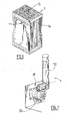
Figure 1 represents a diagrammatic partial perspective view showing an example of an installation for producing and supplying electricity using a fuel cell and provided with a hydrogen supply device of one embodiment of the invention, -
Figure 2 represents a diagrammatic and partial side view in vertical section showing one example of an installation of the invention, -
Figure 3 represents a diagrammatic and partial perspective view showing a detail of an installation conforming toFigure 1 , -
Figure 4 represents a diagrammatic and partial perspective view showing a detail of an arrangement of gas pipes of theFigure 3 installation, -
Figure 5 represents a diagrammatic and partial perspective view showing a detail of a control unit of the installation fromFigure 3 , -
Figure 6 represents a diagrammatic and partial perspective view showing an example of a rack of cylinders of the installation of the invention, -
Figure 7 represents a diagrammatic and partial perspective view showing a detail of one end of a sheath of theFigure 3 installation, -
Figures 8 and 9 represent diagrammatic and partial side views in vertical section and in respective configurations of a detail of a possible embodiment of the installation fromFigure 2 , -
Figures 10 and 11 represent perspective views corresponding toFigures 8 and 9 , respectively, -
Figure 12 represents a diagrammatic and partial view in section of a detail fromFigure 2 showing one method of fixing a protection plate to the cylinders, -
Figure 13 represents two views to a larger scale and in section of a detail fromFigure 2 showing two gas paths in the event of a leak, -
Figure 14 represents a diagrammatic perspective view partially in section of a detail of a frame according to another possible embodiment. - The device of the invention comprises two main components, namely:
- a
frame 3 or, preferably, a pair offrames 3 ofcylinders 8 of gas under pressure (hydrogen), and - a
unit 20 for controlling the gas leaving theracks 3. - As shown notably in
Figures 1 and 2 , eachrack 3 has a bottom 7 forming a robust chassis on which thecylinders 8 are disposed. - Each
rack 3 compriseslateral walls 14 connected to thebottom 7 and delimiting a closed enclosure around thecylinders 8, preferably over the full height of thecylinders 8. Thesewalls 14 form a continuous and solid partition around thecylinders 8. At least some of thewalls 14 might be opened at their lower end. Thesewalls 14 may be fixed or removable and are designed to provide the function of a protective enclosure. - The
rack 3 further comprises aperforated roof 15 connected to the upper ends of thelateral walls 14. - Each
cylinder 8 is equipped with a cylinder connector 9, for example screwed into the threaded orifice of the head of thecylinder 8. Each cylinder connector 9 is connected (in parallel) to acommon tap 10 via connectingpipework 11. On its downstream side, thetap 10 is connected to aconnector 12. Note that the terms "upstream" and "downstream" designate relative positions according to the flow of the gas (here drawing off gas from thecylinders 8 to a consumer application). - The
connector 12 is provided to enable connection of theframes 3 ofcylinders 8 to an installation using the gas from thecylinders 8, for example to supply afuel cell 47 with fuel (hydrogen). Similarly, theconnector 12 downstream of the cylinder is provided to enable connection of thecylinder rack 3 to a packaging centre for filling the cylinders. These drawing off and filling operations are generally carried out by means of high-pressure hoses. - To this end, the
connector 12 is situated in the enclosure adjacent awindow 17 formed in alateral wall 14, preferably in the upper portion of alateral wall 14. - The
racks 3 preferably have identical standardized dimensions and likewise the positioning of thetap 10 and theconnector 12. - As visible in
Figure 2 , eachrack 3 preferably includes aprotective plate 16 positioned over the heads of thecylinders 8, notably to hold them apart. For example, theprotective plate 16 is threaded over the upper end of thecylinders 8 by means ofrespective orifices 21. For example, thecylinders 8 are held apart from each other at a distance up to 3 cm and preferably up to 1 cm. This function of theplate 16 is particularly advantageous if thecylinders 8 are made of a composite material, to avoid contact between thecylinders 8. - As can be seen in
Figure 12 , thecylinders 8 are for example fixed in respective orifices of theplate 16 via respective fixing members such asnuts 24 cooperating with a threaded portion of thenecks 223 of thecylinders 8. - Similarly, as shown in
Figures 13 and 14 , at least a portion of the face of thelateral walls 14 situated facing theborder 17 of theplate 16 may be bent or curved to form a gas passage diverging upwardly between theplate 16 and thewall 14. In this way, any gas G leaking above theplate 16 does not tend to diffuse under theplate 16 but rather upward. Similarly, any gas leaking under theplate 16 tends to escape upward via the passage between the plate and thelateral walls 14. These gas paths are symbolized by dashed line arrows inFigure 13 . - As shown in the
Figure 14 variant, a lateral wall or thelateral walls 14 may be composed of two panels assembled together, respectively anupper panel 130 and alower panel 140. The rack may include a skeleton structure formed of bars, theupper panel 130 and thelower panel 140 being fixed to thebars 240 via fixingmembers 230 such as systems of bolts. Similarly, as may be seen inFigure 14 , the lower border of theupper panel 130 may be received in asupport groove 241 situated at the level of the upper edge of thelower panel 140. - Moreover, in the event of leaking of inflammable gas at the level of a connector 9 of a
cylinder 8, theprotective plate 16 prevents aggression of the other cylinders notably should a flame (flaming spear) be formed on one of thecylinders 8. - The
plate 16 preferably has itsedges 77 raised upward to prevent any confinement of gas in the event of a leak on the body of acylinder 8. To this end, the border of the plate is spaced from thelateral walls 14 to avoid forming a closed volume between thecylinders 8 and thewalls 14. - The
roof 15 of eachrack 3 has an open apertured structure (for example consisting or bars and/or a grille). This makes it possible to evacuate gas leaks in a natural way, channelling them upward and out of therack 3. - The
roof 15 is preferably equipped with a grille to prevent any intrusion and malicious action on theconnectors 9, 12 and thetap 10. - In the normal configuration the
tap 10 and theconnector 12 are thus accessible only via thewindow 17. Thiswindow 17 is formed for example by a cutout in awall 14. In this way, the safety area in the horizontal plane is limited to the surface of thebottom 7 of therack 3. - In the
Figure 1 example, tworacks 3 ofcylinders 8 are connected to acommon control unit 20 for controlling the drawn off gas. Thisgas control unit 20 has the main function of assuring and controlling the distribution of gas from thecylinders 8 in theracks 3 to user apparatus, notably afuel cell 47. - The
control unit 20 is for example installed on a concrete foundation slab of the installation or any other appropriate structure. - The
control unit 20 forms a closed box. Thisunit 20 accommodates within it agas control circuit 123. - This
circuit 123 preferably has two ends connected in parallel to anautomatic changeover device 22 via twopressure regulators 23 to expand the gas from thecylinders 8 to a lower pressure required by thefuel cell 47 and to regulate the pressure (fig. 3 ) . Thecircuit 123 preferably also includes one ormore pressure transmitters 24 that measure and transmit continuously the evolution of the pressure in eachrack 3 ofcylinders 8. Thecircuit 123 also includes purge valves 25 necessary for conditioning the lines when starting up, during maintenance and during changing of the racks 3 (cf.Figure 2 which shows diagrammatically the units of the circuits 123). - The
circuit 123 preferably also includes an automatic isolating valve 26 for shutting off the feed to thecell 47 in the event of a problem. This valve 26 preferably supplements a downstream valve controlling the supply of gas to thecell 47. - The
circuit 123 also includes safety valves 27 and one or more general feed valves 28 situated upstream of thecell 47. - All these components are preferably grouped on a board and are installed inside the
unit 20 in a volume delimited for example by twolateral separating walls 29. - In its upper part the
unit 20 is preferably closed by a fine-mesh lid 30 to prevent direct sight of the internal units of thecircuit 123 whilst guaranteeing the absence of confinement of gas in the event of a leak (fig. 5 ). Above the units of the circuit theunit 20 may include alid 31 that is inclined in the normal position. Theinclined lid 31, constituted of sheet metal, for example, forms a screen favouring flow in the event of inclement weather. This structure also protects users in the event of a blowback. - Vertically in line with each
window 17 enabling access to aconnector 12 the device comprises avertical protection sheath 32 extending between thecontrol unit 20 and thewindow 17. Eachsheath 32 accommodates a gas draw-offpipe 33 having anupstream end 36 intended to be selectively connected to theconnector 12 of the rack and a downstream end connected to thecircuit 123 of thecontrol unit 20. - Each
sheath 32 also accommodates a gas evacuation pipe (or chimney) 34 having an upstream first end connected to thecontrol circuit 123 and a downstream end emerging to the exterior of the device, in the upper part of therack 3, to release the gas purged or released by thecontrol circuit 123. In other words, theevacuation pipe 34 has a height designed to reject the inflammable gas at a sufficient height to prevent all risk of burns in the event of ignition. These twoevacuation pipes 34 form a double evacuation system having a low unitary flow rate compared to known installations with only one evacuation pipe. - A high-pressure draw-off
pipe 33 emerges from the upper end of thesheath 32. This upper end of eachpipe 33 is provided with aconnector 36 complementary to theconnector 12 of therack 3 to enable connection via thewindow 17 in thelateral wall 14. - The lower end of each
sheath 32 emerges into theunit 20 with the corresponding draw-offpipe 33 and thecorresponding evacuation pipe 34. These lower ends of the draw-offpipes 33 andevacuation pipes 34 are connected, preferably horizontally connected, to thecontrol circuit 123 of theunit 20. - The lower end of the
sheath 32 is preferably anchored mechanically to theunit 20 via an elastic articulation that allows movement in a horizontal plane (of the order of 250 mm) of the upper end of the sheath relative to therack 3. This enables the upper end of thesheath 32 to be moved closer to therack 3 to make connections. As shown by way of example inFigure 7 , theelastic articulation 38 is for example of the type provided with a polymer and/or spring joint between thesheath 32 and an anchorage in the unit. The architecture of the joint comprises two cylindrical portions connected perpendicularly and each enabling for example a rotation of 30 degrees about their respective axis. For example the joint is of the type marketed by the company Paulstra® under reference BL56518. - As may be seen in
Figure 4 , the upstream end of the gas evacuation pipe 34 (situated in the unit 20) comprises aportion 40 wound with one or more turns enabling adaptation of the heightwise position of the upper end of thegas evacuation pipe 34. - Similarly, the downstream end of the draw-off
pipe 33 situated in thecontrol unit 20 preferably comprises awound portion 39 preferably forming a plurality of turns, for example horizontal turns. This structure enables adaptation of the heightwise position of theupstream end 36 adapted to be connected to theconnector 12 of therack 3. Thepipes sheath 32. - The amplitude of these possible vertical movements is preferably equal to the height of the unit 20 (for example from 250 to 300 mm).
- Given the respective lengths of the pipework elements of the
pipes 33, 34 (for example from 1 to 3 m) and the structure of the system, it is not necessary to provide intermediate welds on thepipes pipes pipes pipes - When the ends 36 of the draw-off
pipes 33 are connected to therespective connectors 12 of theracks 3, each connection is preferably protected by a respectiveremovable cap 41. - For example, as may be seen in
Figures 2 ,3 ,8 and 9 , a slidingcap 41 may be mounted around the upper end of thesheath 32. - For example, in the position protecting the
connector cap 41 is hooked onto theframe 30 at the level of a generatrix or border, for example an upper border, of the window 17 (seeFigures 3 ,8 and 10 ). For example, thecap 41 is selectively hooked in a high position protecting theconnectors lug 141. Thecap 41 is of sheet metal for example (like thewalls 41 and the sheath 32) and the hookinglug 141 may be formed by bending the sheet metal of thecap 41 to a hook shape. A locking member may if necessary be provided for selectively locking the cap to therack 3 in the position protecting the connectors (the protection position forming a screen preventing access to theseconnectors - According to an advantageous feature, the device preferably comprises a restraining
cable 44 for preventing movement of arack 3 of cylinders when the connector of therack 3 is still connected to the high-pressure draw-offpipe 33. This could pull off the high-pressure pipe 3 which could lead to serious injuries. An operator might forget to shut thetap 10 of the rack and disconnect theconnectors - This restraining
cable 44 has afirst end 144 hooked onto a fixed anchorage separate from the device, for example on a concrete foundation slab. The second end of the restrainingcable 44 is selectively hooked, for example via anattachment member 45 such as a carabiner, over an attachment point of the rack. In the attached position, thecable 44 prevents movement of arack 3 ofcylinders 8. - To oblige the operator to attach/detach this restraining
cable 44, the second end of thecable 44 preferably also comprises acover 46, such as a metal plate with dimensions slightly greater than the area of theaccess window 17 to theconnector 12 of therack 3. When thesecond end 45 of the restrainingcable 44 is hooked onto the rack at its attachment point, thecover 46 is placed between thesheath 32 and thelateral wall 14 of the rack 3 (seeFigures 10 and 11 ). - When the
sheath 32 is moved into a relatively low position relative to the window 17 (seeFigures 9 and 11 ), access to theconnector 12 by an operator is possible only when thesecond end 45 of the restrainingcable 44 is unhooked from its point of attachment to the rack (the default position of thecover 46 prevents such access). - The
sheath 32 preferably cannot be placed in a relatively high position relative to thewindow 17 if thecover 46 is not disposed over thewindow 17 in a position blocking the window necessitating attachment of thesecond end 45 of the cable to its point of attachment on therack 3. To be able to place thecover 46 in the high position and hook thecover 46 onto the rack via thelug 141, it is necessary for thecover 46 to be pressed into position over thewindow 17. Thecover 46 can be retained only by hooking the second end of thecable 45 over its attachment point on therack 3. Thecover 46 is preferably painted in a bright colour to render it visible and to identify easily incorrect manipulation by an operator who has forced thecover 46 closed without connecting thecable 45 beforehand. - When the
sheath 32 is in the high position (Figures 8 and 10 ), thecover 46 blocks thewindow 17 and the height of thesheath 32 prevents the operator from accessing theconnector 12 via the upper opening of thecover 46. - A
fuel cell 47 may be positioned symmetrically against one end of the device. The fluid connection of thecircuit 123 to thecell 47 may be effected via low-pressure circuitry without special tools. Once the connection has been made, thevarious caps 41 are fitted to conceal and protect all the sensitive elements of the installation. - The
cell 47 is fed with hydrogen from one rack and then, when the rack is empty, from the second (via the switch of the control circuit 123), and the empty rack may be replaced. - The footprint of such an installation may be contained to within 3 m x 1.5 m, which is the equivalent of a generator set. This architecture may be used for any compressed gas installation for which the footprint must be small and safety conditions must be guaranteed.
Claims (14)
- Device for supplying gas under pressure, notably hydrogen, comprising a rack (3) accommodating a plurality of cylinders (8) of gas under pressure, the rack (3) comprising a bottom (7) on which the cylinders (8) rest and lateral walls (14) connected to the bottom (7) and delimiting a closed enclosure around the cylinders (8), the rack further comprising a perforated roof (15) connected to the upper ends of the lateral walls (14), the device comprising a common tap (10) having an upstream end fluidically connected to the orifice of each of the cylinders (8), the tap (10) having a downstream end connected to a fluidic connector (12) selectively connectable to a member for filling the cylinders (8) with gas and/or drawing off gas, characterized in that the connector (12) is situated in the enclosure adjacent a window (17) formed in a lateral wall (14), the device further comprising a unit (20) for controlling the gas drawn off from the cylinders (8), the control unit (20) accommodating a circuit (123) for controlling the drawn-off gas, the control circuit (123) comprising at least one pressure regulator (23) the outlet of which is selectively connectable (147) to apparatus (47) using the expanded gas coming from the cylinders (8) in the rack, the device further comprising a protective sheath (32) extending between the control unit (20) and the window (17), the sheath (32) accommodating a gas draw-off pipe (33) having an upstream end (36) selectively connectable to the connector (12) of the rack and a downstream end connected to the circuit (123) of the control unit (20).
- Device according to Claim 1, characterized in that the sheath (32) accommodates a gas evacuation pipe (34) having an upstream first end connected to the control circuit (123) and a downstream end emerging outside the device, in the upper part of the rack (3), to release gas purged or released via the control circuit (123).
- Device according to Claim 2, characterized in that the upstream end of the gas evacuation pipe (34) comprises a wound portion (40) forming at least one turn enabling adaptation of the heightwise position of the downstream end of said gas evacuation pipe (34) relative to the rack (3).
- Device according to any one of Claims 1 to 3, characterized in that the device includes a protective and positioning plate (16) threaded over the upper end of the cylinders (8) via respective orifices, the cylinders (8) being held apart from each other by the plate (16) at a distance up to one centimetre.
- Device according to any one of Claims 1 to 4, characterized in that the control circuit (123) comprises at least one of the following members: a fixed or adjustable pressure regulator (23), a pressure sensor (24) measuring the pressure in the gas pipe (33), a purge pipe provided with at least one purge valve adapted to evacuate selectively gas under pressure present in the control circuit (123), an isolating valve (26) for selectively interrupting the circulation of the fluid coming from the cylinders (8), at least one safety valve (27) for evacuating gas from the circuit in the event of fire, a member for remote transmission of information, notably wireless transfer of pressure information obtained by the pressure sensor, a gas outlet connected to a pipe (147) connectable to apparatus (47) using gas, two gas inlets connected in parallel to a gas outlet via a switch member (22) for connecting the gas outlet and one of the gas inlets in parallel.
- Device according to any one of Claims 1 to 5, characterized in that the protective sheath (32) has a rigid structure, the lower end of the sheath (32) being connected to the control unit (20) via an elastic articulation (38) allowing angular movement of the sheath (32) relative to the unit (20).
- Device according to any one of Claims 1 to 6, characterized in that the downstream end of the draw-off pipe (33) situated in the control unit (20) comprises a wound portion (39) forming at least one turn enabling adaptation of the heightwise position of the upstream end (36) connectable to the connector (12) of the rack (3).
- Device according to any one of Claims 1 to 7, characterized in that it comprises a cap (41) for selectively protecting the connector (12), the cap (41) being mobile outside the enclosure between an active position in which the cap (41) is hooked onto the rack (3) and forms a screen around the window (17) preventing access to the connector (12) and an inactive position in which the cap (41) does not form a screen around the window (17), enabling access to the connector (12).
- Device according to any one of Claims 1 to 8 characterized in that it comprises a restraining cable (44) having a first end hooked onto a fixed anchorage (144) separate from the rack (3) and a second end comprising an attachment member (45) selectively and detachably hooked onto a conjugate attachment point of the rack (3).
- Device according to Claim 9 characterized in that the second end of the restraining cable (44) comprises a cover (46) that blocks access to the connector (12) of the rack if the attachment member (45) of the first end of the restraining cable (44) is not hooked onto its attachment point on the rack (3).
- Device according to Claim 10 characterized in that the sheath (32) is movable vertically between a first relatively low position relative to the window (17) and a relatively high position relative to the window (17), when the attachment member (45) of the first end of the restraining cable (44) is not hooked onto its attachment point on the rack (3), the cover (46) is in a position forming a stop for preventing the sheath (32) from going from its first position to the second position, when the attachment member (45) of the first end of the restraining cable (44) is hooked onto its attachment point on the rack (3) the cover (46) is in a position allowing the sheath (32) to go from its first position to the second position.
- Device according to any one of claims 1 to 11 characterized in that it comprises, displaced on respective bottoms (7), two distinct racks (3) each accommodating a plurality of cylinders (8) of gas under pressure, each rack (3) comprising lateral walls (14) connected to the bottom (7) and delimiting a closed enclosure around the cylinders (8) concerned, over all the height of the cylinders (8), each rack (3) further comprising a perforated roof (15) connected to the upper ends of the lateral walls (14), each rack comprising a tap (10) common to the cylinders (8) in the rack (3), each tap (10) having an upstream end fluidically connected to the orifice of each of the cylinders (8) in the rack (3), each tap (10) having a downstream end connected to a fluidic connector (12) selectively connectable to a member for filling the cylinders (8) with gas and/or drawing off gas, the connector (12) of each rack (3) being situated in the enclosure concerned of the rack (3) and adjacent a window (17) formed in a lateral wall (14) of the rack (3) concerned, the unit (20) for controlling the gas drawn off from the cylinders (8) being common to the two racks (3) of cylinders (8), the circuit (123) of the control unit (20) for controlling the gas drawn off comprising two pressure regulators (23) intended to be connected to the respective connectors (12) of the racks (3), the two regulators being connected in parallel to an automatic or non-automatic switch member (22) assuring selective switching of the gas delivered by a first rack (3) of cylinders (8) and then from the second rack (3) of cylinders to a common outlet (147) connectable to apparatus using the expanded gas coming from one of the racks (3) of cylinders (8).
- Installation for producing and supplying electricity comprising a fuel cell (47), notably of the proton exchanger membrane type, the cell (47) being fed with gaseous hydrogen from a device for supplying hydrogen gas under pressure, characterized in that the device for supplying hydrogen gas under pressure conforms to any one of Claims 1 to 12.
- Installation according to Claim 13, characterized in that it comprises a telecommunication site selectively supplied with electrical power by the fuel cell.
Applications Claiming Priority (1)
| Application Number | Priority Date | Filing Date | Title |
|---|---|---|---|
| IN2078DE2012 | 2012-07-04 |
Publications (2)
| Publication Number | Publication Date |
|---|---|
| EP2682668A2 true EP2682668A2 (en) | 2014-01-08 |
| EP2682668A3 EP2682668A3 (en) | 2017-07-12 |
Family
ID=46690400
Family Applications (1)
| Application Number | Title | Priority Date | Filing Date |
|---|---|---|---|
| EP12179807.8A Withdrawn EP2682668A3 (en) | 2012-07-04 | 2012-08-09 | Device for supplying gas under pressure and installation for producing and supplying electricity comprising such a device |
Country Status (1)
| Country | Link |
|---|---|
| EP (1) | EP2682668A3 (en) |
Cited By (2)
| Publication number | Priority date | Publication date | Assignee | Title |
|---|---|---|---|---|
| CN107611485A (en) * | 2017-10-26 | 2018-01-19 | 力信(江苏)能源科技有限责任公司 | Battery case frock is inserted in one kind dress protection |
| EP4394234A1 (en) * | 2022-12-27 | 2024-07-03 | Equipos Moviles de Campaña Arpa, S.A.U. | Portable and autonomous equipment for supplying hydrogen. |
Family Cites Families (7)
| Publication number | Priority date | Publication date | Assignee | Title |
|---|---|---|---|---|
| US5440477A (en) * | 1991-05-20 | 1995-08-08 | Creative Pathways, Inc. | Modular bottle-mounted gas management system |
| US6240909B1 (en) * | 1999-09-20 | 2001-06-05 | Fab Industries, L.L.C. | Fill block |
| CA2386443C (en) * | 2001-05-17 | 2007-10-23 | Dynetek Industries Ltd. | Replaceable fuel module and method |
| US6786245B1 (en) * | 2003-02-21 | 2004-09-07 | Air Products And Chemicals, Inc. | Self-contained mobile fueling station |
| FR2857632A1 (en) * | 2003-07-18 | 2005-01-21 | Gie Psa Peugeot Citroen | Motor vehicle fuel cell has fuel system comprising air-pressure reducing valve that is disposed near storage unit for preventing system from being exposed to high pressure gas and compresses gas to low pressure |
| US8833088B2 (en) * | 2009-09-08 | 2014-09-16 | Questar Gas Company | Methods and systems for reducing pressure of natural gas and methods and systems of delivering natural gas |
| CN102791359B (en) * | 2010-01-14 | 2015-11-25 | 诚实公司 | Ventilation gas management systems and methods |
-
2012
- 2012-08-09 EP EP12179807.8A patent/EP2682668A3/en not_active Withdrawn
Non-Patent Citations (1)
| Title |
|---|
| None |
Cited By (3)
| Publication number | Priority date | Publication date | Assignee | Title |
|---|---|---|---|---|
| CN107611485A (en) * | 2017-10-26 | 2018-01-19 | 力信(江苏)能源科技有限责任公司 | Battery case frock is inserted in one kind dress protection |
| CN107611485B (en) * | 2017-10-26 | 2024-02-13 | 利信(江苏)能源科技有限责任公司 | Dress protection embolias frock for battery case |
| EP4394234A1 (en) * | 2022-12-27 | 2024-07-03 | Equipos Moviles de Campaña Arpa, S.A.U. | Portable and autonomous equipment for supplying hydrogen. |
Also Published As
| Publication number | Publication date |
|---|---|
| EP2682668A3 (en) | 2017-07-12 |
Similar Documents
| Publication | Publication Date | Title |
|---|---|---|
| EP2682667A2 (en) | A pressurized gas cylinders pallet | |
| US11581601B1 (en) | Fire suppression system for lithium-ion battery containers | |
| KR102185759B1 (en) | Fire suppression system for ess | |
| CN210040091U (en) | Fixed circuit breaker | |
| CN114432620A (en) | Electrochemistry energy storage power station fire extinguishing system | |
| AU2024278371A1 (en) | Multi-stage energy storage fire-fighting system | |
| EP2682668A2 (en) | Device for supplying gas under pressure and installation for producing and supplying electricity comprising such a device | |
| CN114432631A (en) | Automatic water spraying fire extinguishing system and fire extinguishing method for cooling tower | |
| CN221057578U (en) | Energy storage container | |
| CN108619635A (en) | Compressed-air foam intelligent fire device for outer floating roof crude oil storage tank | |
| CN108470928A (en) | Fuel system and its detection method for unmanned plane fuel cell | |
| CN117673610A (en) | Battery energy storage system cabin | |
| CN210372889U (en) | Intelligent gas underground pressure regulating device | |
| KR102219631B1 (en) | A distributing board connected photovoltaic generating apparatus and energy storage system | |
| CN216592079U (en) | Shelter containing air purification system | |
| CN214949201U (en) | Ignition device of asphalt mixing station combustor | |
| CN223504755U (en) | Fire control cooling water supply device | |
| CN223263335U (en) | Fire control foam liquid feeding device | |
| CN213049094U (en) | Fire extinguishing device for fire-fighting equipment | |
| CN211357544U (en) | Container type fire-fighting system | |
| CN220727913U (en) | Valve box and marine hydrogen system | |
| CN208904584U (en) | A sealed oil transfer arm junction box | |
| CN215061362U (en) | Oil gas field long distance pipeline safety monitoring device | |
| CN221513339U (en) | Intelligent battery fire-fighting system for power exchange station | |
| CN101586738A (en) | A kind of safety configuration structure of liquid chlorine storage equipment |
Legal Events
| Date | Code | Title | Description |
|---|---|---|---|
| PUAI | Public reference made under article 153(3) epc to a published international application that has entered the european phase |
Free format text: ORIGINAL CODE: 0009012 |
|
| AK | Designated contracting states |
Kind code of ref document: A2 Designated state(s): AL AT BE BG CH CY CZ DE DK EE ES FI FR GB GR HR HU IE IS IT LI LT LU LV MC MK MT NL NO PL PT RO RS SE SI SK SM TR |
|
| AX | Request for extension of the european patent |
Extension state: BA ME |
|
| PUAL | Search report despatched |
Free format text: ORIGINAL CODE: 0009013 |
|
| AK | Designated contracting states |
Kind code of ref document: A3 Designated state(s): AL AT BE BG CH CY CZ DE DK EE ES FI FR GB GR HR HU IE IS IT LI LT LU LV MC MK MT NL NO PL PT RO RS SE SI SK SM TR |
|
| AX | Request for extension of the european patent |
Extension state: BA ME |
|
| RIC1 | Information provided on ipc code assigned before grant |
Ipc: F17C 13/04 20060101ALI20170607BHEP Ipc: F17C 13/08 20060101AFI20170607BHEP Ipc: F17C 7/00 20060101ALI20170607BHEP Ipc: F17C 5/06 20060101ALI20170607BHEP |
|
| STAA | Information on the status of an ep patent application or granted ep patent |
Free format text: STATUS: THE APPLICATION IS DEEMED TO BE WITHDRAWN |
|
| 18D | Application deemed to be withdrawn |
Effective date: 20180113 |