EP2682641A1 - Multi-shaft drive device - Google Patents
Multi-shaft drive device Download PDFInfo
- Publication number
- EP2682641A1 EP2682641A1 EP12752273.8A EP12752273A EP2682641A1 EP 2682641 A1 EP2682641 A1 EP 2682641A1 EP 12752273 A EP12752273 A EP 12752273A EP 2682641 A1 EP2682641 A1 EP 2682641A1
- Authority
- EP
- European Patent Office
- Prior art keywords
- output
- selector
- shaft
- rotation shaft
- case
- Prior art date
- Legal status (The legal status is an assumption and is not a legal conclusion. Google has not performed a legal analysis and makes no representation as to the accuracy of the status listed.)
- Withdrawn
Links
- 230000007246 mechanism Effects 0.000 claims abstract description 9
- 230000001105 regulatory effect Effects 0.000 abstract 1
- 230000000694 effects Effects 0.000 description 4
- 238000003780 insertion Methods 0.000 description 3
- 230000037431 insertion Effects 0.000 description 3
- 230000002093 peripheral effect Effects 0.000 description 3
- 238000012986 modification Methods 0.000 description 2
- 230000004048 modification Effects 0.000 description 2
- 230000006835 compression Effects 0.000 description 1
- 238000007906 compression Methods 0.000 description 1
- 238000006073 displacement reaction Methods 0.000 description 1
Images



Classifications
-
- F—MECHANICAL ENGINEERING; LIGHTING; HEATING; WEAPONS; BLASTING
- F16—ENGINEERING ELEMENTS AND UNITS; GENERAL MEASURES FOR PRODUCING AND MAINTAINING EFFECTIVE FUNCTIONING OF MACHINES OR INSTALLATIONS; THERMAL INSULATION IN GENERAL
- F16H—GEARING
- F16H1/00—Toothed gearings for conveying rotary motion
- F16H1/02—Toothed gearings for conveying rotary motion without gears having orbital motion
- F16H1/20—Toothed gearings for conveying rotary motion without gears having orbital motion involving more than two intermeshing members
- F16H1/22—Toothed gearings for conveying rotary motion without gears having orbital motion involving more than two intermeshing members with a plurality of driving or driven shafts; with arrangements for dividing torque between two or more intermediate shafts
-
- F—MECHANICAL ENGINEERING; LIGHTING; HEATING; WEAPONS; BLASTING
- F16—ENGINEERING ELEMENTS AND UNITS; GENERAL MEASURES FOR PRODUCING AND MAINTAINING EFFECTIVE FUNCTIONING OF MACHINES OR INSTALLATIONS; THERMAL INSULATION IN GENERAL
- F16H—GEARING
- F16H37/00—Combinations of mechanical gearings, not provided for in groups F16H1/00 - F16H35/00
- F16H37/02—Combinations of mechanical gearings, not provided for in groups F16H1/00 - F16H35/00 comprising essentially only toothed or friction gearings
- F16H37/06—Combinations of mechanical gearings, not provided for in groups F16H1/00 - F16H35/00 comprising essentially only toothed or friction gearings with a plurality of driving or driven shafts; with arrangements for dividing torque between two or more intermediate shafts
- F16H37/065—Combinations of mechanical gearings, not provided for in groups F16H1/00 - F16H35/00 comprising essentially only toothed or friction gearings with a plurality of driving or driven shafts; with arrangements for dividing torque between two or more intermediate shafts with a plurality of driving or driven shafts
-
- B—PERFORMING OPERATIONS; TRANSPORTING
- B60—VEHICLES IN GENERAL
- B60N—SEATS SPECIALLY ADAPTED FOR VEHICLES; VEHICLE PASSENGER ACCOMMODATION NOT OTHERWISE PROVIDED FOR
- B60N2/00—Seats specially adapted for vehicles; Arrangement or mounting of seats in vehicles
- B60N2/02—Seats specially adapted for vehicles; Arrangement or mounting of seats in vehicles the seat or part thereof being movable, e.g. adjustable
- B60N2/0296—Central command actuator to selectively switch on or engage one of several special purpose circuits or mechanisms
-
- F—MECHANICAL ENGINEERING; LIGHTING; HEATING; WEAPONS; BLASTING
- F16—ENGINEERING ELEMENTS AND UNITS; GENERAL MEASURES FOR PRODUCING AND MAINTAINING EFFECTIVE FUNCTIONING OF MACHINES OR INSTALLATIONS; THERMAL INSULATION IN GENERAL
- F16H—GEARING
- F16H1/00—Toothed gearings for conveying rotary motion
- F16H1/02—Toothed gearings for conveying rotary motion without gears having orbital motion
- F16H1/20—Toothed gearings for conveying rotary motion without gears having orbital motion involving more than two intermeshing members
- F16H1/22—Toothed gearings for conveying rotary motion without gears having orbital motion involving more than two intermeshing members with a plurality of driving or driven shafts; with arrangements for dividing torque between two or more intermediate shafts
- F16H1/222—Toothed gearings for conveying rotary motion without gears having orbital motion involving more than two intermeshing members with a plurality of driving or driven shafts; with arrangements for dividing torque between two or more intermediate shafts with non-parallel axes
-
- F—MECHANICAL ENGINEERING; LIGHTING; HEATING; WEAPONS; BLASTING
- F16—ENGINEERING ELEMENTS AND UNITS; GENERAL MEASURES FOR PRODUCING AND MAINTAINING EFFECTIVE FUNCTIONING OF MACHINES OR INSTALLATIONS; THERMAL INSULATION IN GENERAL
- F16H—GEARING
- F16H19/00—Gearings comprising essentially only toothed gears or friction members and not capable of conveying indefinitely-continuing rotary motion
- F16H19/02—Gearings comprising essentially only toothed gears or friction members and not capable of conveying indefinitely-continuing rotary motion for interconverting rotary or oscillating motion and reciprocating motion
- F16H19/04—Gearings comprising essentially only toothed gears or friction members and not capable of conveying indefinitely-continuing rotary motion for interconverting rotary or oscillating motion and reciprocating motion comprising a rack
-
- F—MECHANICAL ENGINEERING; LIGHTING; HEATING; WEAPONS; BLASTING
- F16—ENGINEERING ELEMENTS AND UNITS; GENERAL MEASURES FOR PRODUCING AND MAINTAINING EFFECTIVE FUNCTIONING OF MACHINES OR INSTALLATIONS; THERMAL INSULATION IN GENERAL
- F16H—GEARING
- F16H21/00—Gearings comprising primarily only links or levers, with or without slides
- F16H21/10—Gearings comprising primarily only links or levers, with or without slides all movement being in, or parallel to, a single plane
- F16H21/16—Gearings comprising primarily only links or levers, with or without slides all movement being in, or parallel to, a single plane for interconverting rotary motion and reciprocating motion
- F16H21/18—Crank gearings; Eccentric gearings
- F16H21/22—Crank gearings; Eccentric gearings with one connecting-rod and one guided slide to each crank or eccentric
- F16H21/28—Crank gearings; Eccentric gearings with one connecting-rod and one guided slide to each crank or eccentric with cams or additional guides
-
- F—MECHANICAL ENGINEERING; LIGHTING; HEATING; WEAPONS; BLASTING
- F16—ENGINEERING ELEMENTS AND UNITS; GENERAL MEASURES FOR PRODUCING AND MAINTAINING EFFECTIVE FUNCTIONING OF MACHINES OR INSTALLATIONS; THERMAL INSULATION IN GENERAL
- F16H—GEARING
- F16H25/00—Gearings comprising primarily only cams, cam-followers and screw-and-nut mechanisms
- F16H25/18—Gearings comprising primarily only cams, cam-followers and screw-and-nut mechanisms for conveying or interconverting oscillating or reciprocating motions
-
- F—MECHANICAL ENGINEERING; LIGHTING; HEATING; WEAPONS; BLASTING
- F16—ENGINEERING ELEMENTS AND UNITS; GENERAL MEASURES FOR PRODUCING AND MAINTAINING EFFECTIVE FUNCTIONING OF MACHINES OR INSTALLATIONS; THERMAL INSULATION IN GENERAL
- F16H—GEARING
- F16H3/00—Toothed gearings for conveying rotary motion with variable gear ratio or for reversing rotary motion
- F16H3/02—Toothed gearings for conveying rotary motion with variable gear ratio or for reversing rotary motion without gears having orbital motion
- F16H3/20—Toothed gearings for conveying rotary motion with variable gear ratio or for reversing rotary motion without gears having orbital motion exclusively or essentially using gears that can be moved out of gear
- F16H3/22—Toothed gearings for conveying rotary motion with variable gear ratio or for reversing rotary motion without gears having orbital motion exclusively or essentially using gears that can be moved out of gear with gears shiftable only axially
-
- F—MECHANICAL ENGINEERING; LIGHTING; HEATING; WEAPONS; BLASTING
- F16—ENGINEERING ELEMENTS AND UNITS; GENERAL MEASURES FOR PRODUCING AND MAINTAINING EFFECTIVE FUNCTIONING OF MACHINES OR INSTALLATIONS; THERMAL INSULATION IN GENERAL
- F16H—GEARING
- F16H37/00—Combinations of mechanical gearings, not provided for in groups F16H1/00 - F16H35/00
- F16H37/02—Combinations of mechanical gearings, not provided for in groups F16H1/00 - F16H35/00 comprising essentially only toothed or friction gearings
- F16H37/06—Combinations of mechanical gearings, not provided for in groups F16H1/00 - F16H35/00 comprising essentially only toothed or friction gearings with a plurality of driving or driven shafts; with arrangements for dividing torque between two or more intermediate shafts
-
- F—MECHANICAL ENGINEERING; LIGHTING; HEATING; WEAPONS; BLASTING
- F16—ENGINEERING ELEMENTS AND UNITS; GENERAL MEASURES FOR PRODUCING AND MAINTAINING EFFECTIVE FUNCTIONING OF MACHINES OR INSTALLATIONS; THERMAL INSULATION IN GENERAL
- F16D—COUPLINGS FOR TRANSMITTING ROTATION; CLUTCHES; BRAKES
- F16D23/00—Details of mechanically-actuated clutches not specific for one distinct type
- F16D23/12—Mechanical clutch-actuating mechanisms arranged outside the clutch as such
- F16D2023/123—Clutch actuation by cams, ramps or ball-screw mechanisms
-
- F—MECHANICAL ENGINEERING; LIGHTING; HEATING; WEAPONS; BLASTING
- F16—ENGINEERING ELEMENTS AND UNITS; GENERAL MEASURES FOR PRODUCING AND MAINTAINING EFFECTIVE FUNCTIONING OF MACHINES OR INSTALLATIONS; THERMAL INSULATION IN GENERAL
- F16D—COUPLINGS FOR TRANSMITTING ROTATION; CLUTCHES; BRAKES
- F16D2125/00—Components of actuators
- F16D2125/18—Mechanical mechanisms
- F16D2125/20—Mechanical mechanisms converting rotation to linear movement or vice versa
- F16D2125/22—Mechanical mechanisms converting rotation to linear movement or vice versa acting transversely to the axis of rotation
- F16D2125/28—Cams; Levers with cams
-
- Y—GENERAL TAGGING OF NEW TECHNOLOGICAL DEVELOPMENTS; GENERAL TAGGING OF CROSS-SECTIONAL TECHNOLOGIES SPANNING OVER SEVERAL SECTIONS OF THE IPC; TECHNICAL SUBJECTS COVERED BY FORMER USPC CROSS-REFERENCE ART COLLECTIONS [XRACs] AND DIGESTS
- Y10—TECHNICAL SUBJECTS COVERED BY FORMER USPC
- Y10T—TECHNICAL SUBJECTS COVERED BY FORMER US CLASSIFICATION
- Y10T74/00—Machine element or mechanism
- Y10T74/19—Gearing
- Y10T74/19019—Plural power paths from prime mover
Definitions
- the present invention relates to a multi-shaft drive device that is preferably applied to for example an electric vehicle seat and that drives plural output shafts with a single motor.
- Many vehicle seats are of a type enabling adjustment of position to plural locations, for example sliding the overall seat in the front-rear direction, moving the height of the seat face up and down, or reclining the seatback (backrest) to suit the build and posture of an occupant.
- Such adjustment of movable locations may be performed manually, however more convenient electric seats are provided that use the drive of a motor to perform adjustments.
- a selector for selecting the output shaft to which to transmit the power of the motor is configured including a rack and a pinion
- an object of the present invention is to obtain a multi-shaft drive device capable of protecting a rack and pinion from operation load input to a selector.
- a multi-shaft drive device includes: a single motor that is fixed to a case and that drives plural movable mechanisms mounted to a vehicle; an input side gear that is provided inside the case and that transmits power of the motor; an output side gear that is provided so as to be capable of projecting forwards and retreating with respect to the input side gear, thereby selectively enmeshing with the input side gear, and transmitting power transmitted from the input side gear to the movable mechanism; a selector that is provided with a rack to allow the selector to slide in one direction and an opposite direction to the one direction, that presses a portion of the output side gear to move the output side gear back, and that disconnects enmeshing between the output side gear and the input side gear; a rotation shaft that is provided with a pinion that enmeshes with the rack provided to the selector, the rotation shaft rotating about its axis due to operation force input to an operation means so as to slide the selector; and a restriction portion that is provided to a side of the operation means
- operation force input into the operation means is transmitted to the rack through the pinion by turning the rotation shaft provided with the pinion using the operation means.
- the selector that is provided with the rack slides as a result. Further, a portion of the selector presses the portion of the output side gear due to the sliding of the selector, thereby moving the output side gear back. Enmeshing between the output side gear and the input side gear is disconnected as a result.
- the output side gear projects forwards. The output side gear enmeshes with the input side gear as a result.
- the restriction portion that restricts the rotation angle of the rotation shaft is provided to the side of the operation means including the rotation shaft. Such a configuration accordingly prevents operation force input into the rotation shaft from being borne by the rack and pinion such as occurs in a configuration wherein the rotation angle of the rotation shaft is restricted by the selector contacting for example the case.
- a multi-shaft drive device is the first aspect, wherein the restriction portion includes: the operation means fixed to the rotation shaft; and a contacted portion that is provided to the case and is contacted by a portion of the operation means.
- operation force input into the rotation shaft is borne by the portion of the operation means contacting the contacted portion provided to the case.
- operation force input into the rotation shaft is prevented from being borne directly by the rack and pinion.
- a multi-shaft drive device is the first aspect, wherein the restriction portion includes: a contact portion that is provided inside the case and that is formed to a portion of the rotation shaft; and a contacted portion that is provided to the case and that is contacted by the contact portion.
- operation force input into the rotation shaft is borne by the contact portion formed to a portion of the rotation shaft contacting the contacted portion provided to the case.
- the contact portion and the contacted portion are provided inside the case of the multi-shaft drive device, thereby suppressing any impact on the external design of the multi-shaft drive device as a result of providing the contact portion and the contacted portion.
- the multi-shaft drive device exhibits the excellent advantageous effect of being capable of protecting the rack and pinion from operation load input to the selector.
- the multi-shaft drive device of the third aspect exhibits the excellent advantageous effect of being capable of protecting the rack and pinion from operation force input to the selector without imposing restrictions on the external design of the multi-shaft drive device.
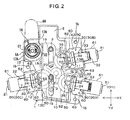
- Fig. 1 and Fig. 2 are a perspective view and a plan view illustrating a multi-shaft drive device according to an exemplary embodiment.
- Fig. 1 and Fig. 2 illustrate a case 1 including a recessed area 2 that opens upwards, a selector 10 housed in the recessed area 2 of the case 1, and a motor 20 fixed to a lower portion of the case 1.
- the opening of the recessed area 2 of the case 1 is covered by a cover, not illustrated in the drawings, that is fixed to the case 1.
- the selector 10 is a substantially rectangular plate shaped member that is long in the Y direction in Fig. 2 , and is formed with two guide holes 19 that extend in the Y direction at a width direction (X direction) central portion.
- Guide projections 3 that project out from a bottom portion of the recessed area 2 are respectively inserted into the guide holes 19.
- the selector 10 is supported so as to be capable of sliding in the Y direction with the guide holes 19 guided by the guide projections 3.
- the side face on the right hand side in Fig. 2 is formed with a first cam face 11.
- the side face on the left hand side is formed with a second cam face 12 at a lower side and formed with a rack 18 with a row of teeth running in the Y direction at an upper side.
- a rotation shaft 16 that is rotatably supported on the case 1 is provided with a pinion 17 formed so as to extend towards the rotation shaft 16 radial direction outside.
- the pinion 17 is formed around the circumferential direction of the rotation shaft 16, with contact portions 17A configured at both circumferential direction end portions of the pinion 17, and the contact portion 17A contacts a vertical wall portion 1A of the case 1 that forms the recessed area 2 and serves as a contacted portion.
- the rotation angle of the rotation shaft 16 is restricted due to the contact portions 17A contacting the vertical wall portion 1A.
- the pinion 17 is enmeshed with the rack 18.
- a dial 69 serving as an operation means is fixed to the rotation shaft 16. The pinion 17 rotates when the dial 69 is rotated, thereby moving the selector 10 back and forth along the Y direction through the rack 18 according to the rotation direction of the dial 69.
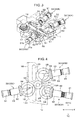
- output portions 30 are disposed facing each of the cam faces 11, 12 on both X direction sides of the selector 10.
- two output portions 30 (a first output portion 30A and a second output portion 30B) are disposed separated from each other in the Y direction and facing the first cam face 11, and one output portion 30 (a third output portion 30C) is disposed facing the second cam face 12.
- the output portions 30 are housed in housing portions 60 formed to the case 1 as illustrated in Fig. 1 and Fig. 2 .
- a motor shaft 21 of the motor 20 projects upwards.
- the motor shaft 21 can be rotated forwards or in reverse.
- a pinion 22 is fixed to the motor shaft 21.
- Three input side clutch members 50 corresponding to the respective output portions 30 are provided to the periphery of the pinion 22 and are rotatably supported on the case 1.
- Each of the input side clutch members 50 is of a similar configuration, and includes an input gear 51 that enmeshes with the pinion 22 configured by a flattened cog, and an input side bevel gear 52 serving as an input side gear integrally formed to an upper face of the input gear 51.
- the input side bevel gears 52 are rotatably supported on the case 1 for each of the input side clutch members 50, thereby positioning the input side clutch members 50 at specific positions.
- the motor 20 is switched ON/OFF, and the rotation direction thereof is selected, for example by a switch provided to the dial 69. When the motor 20 is actuated, all of the input side clutch members 50 rotate.
- each of the output portions 30 are of similar configuration.
- the output portions 30 are configured including an output shaft 31 disposed in a state facing the cam face 11 (12), an output side clutch member 32 provided so as to be capable of rotating together as a unit with the output shaft 31, and also capable of projecting forwards or retreating along the output shaft 31 axial direction with respect to the cam face 11 (12), and a coil spring 36 that biases the output side clutch member 32 so as to project forwards towards the input side bevel gear 52.
- the output shafts 31 are rotatably supported by support portions 61 configuring the housing portions 60 of the case 1.
- the output shafts 31 are respectively connected through torque cables, not illustrated in the drawings, to movable mechanisms provided to an electric seat in a vehicle, for example, a mechanism for adjusting the height of a seat face, a reclining mechanism for adjusting the angle of the seatback (backrest portion), and a mechanism for adjusting the front-rear position of the seat.
- One end portions of the torque cables are inserted into mounting holes 31b (see Fig. 1 ) of rectangular cross-section profile that are formed to rear end faces of the output shafts 31, and rotate together with the output shafts 31.
- the output side clutch members 32 are each configured including: a circular cylinder shaped slide shaft 33 that is externally mounted to the selector 10 side of the output shaft 31; an output side bevel gear 34 serving as an output side gear that has a toothed face integrally formed to a leading end side of the slide shaft 33 facing towards the selector 10 side; a pin (contact portion) 35 that projects out in the axial direction from the center of the output side bevel gear 34; and the coil spring 36 that biases the slide shaft 33 in the direction of the selector 10.
- An inner peripheral face of the slide shaft 33 is not capable of relative rotation in the circumferential direction with respect to the outer peripheral face of the output shaft 31, namely the slide shaft 33 is capable of rotating as a unit together with the output shaft 31, and the two are spline joined together so as to allow sliding along the axial direction.
- the slide shafts 33 are accordingly capable of projecting forwards or retreating in the output shaft 31 axial direction with respect to the cam faces.
- the coil spring 36 is housed inside the output shaft 31 and the slide shaft 33 in a compressed state, and biases the slide shaft 33 from the output shaft 31 towards the cam faces 11 (12).
- Leading ends of the pins 35 of the output side clutch members 32 accordingly abut the cam faces 11 (12) when facing the cam faces 11 (12).
- Leading end faces of the pins 35 are formed with spherical face shapes, and make sliding contact with the abutting cam faces 11 (12) when the selector 10 is moved in the Y direction by the dial 69 described above.
- the first cam face 11 of the selector 10 is formed with a first recessed portion 13A and a second recessed portion 13B serving as cam portions corresponding to the first output portion 30A and the second output portion 30B, and the second cam face 12 is formed with a third recessed portion 13C serving as a cam portion corresponding to the third output portion 30C.
- the selector 10 is operated so as to move along the Y direction as described above, the pin 35 of any one of the output portions 30 faces the corresponding recessed portion 13A (13B, 13C).
- the output side clutch member 32 is biased as a whole towards the cam face 11 (12) by the coil spring 36, such that the pin 35 projects out and fits into the recessed portion 13A (13B, 13C).
- the output side clutch member 32 slides as a whole in the selector 10 direction when the pin 35 projects out and fits into the recessed portion 13A (13B, 13C), and the output side bevel gear 34 enmeshes with the input side bevel gear 52, achieving a clutch connected state.
- the motor 20 is actuated and the input side clutch member 50 rotates with the clutch connected, the rotation is transmitted from the input side bevel gear 52 to the enmeshed output side bevel gear 34, and the overall output side clutch member 32 rotates.
- the rotation of the slide shaft 33 is transmitted to the output shaft 31 and the output shaft 31 rotates, thereby rotating and actuating the torque cable.
- the pin 35 When the pin 35 is not in a state facing the recessed portion 13A (13B, 13C), the pin 35 contacts the cam face 11 (12) at a portion other than the recessed portion 13A (13B, 13C), the cam face 11 (12) pressing the pin 35 towards the output shaft 31 side against the coil spring 36. When this occurs, the output side bevel gear 34 separates from the input side bevel gear 52 to achieve a clutch disconnected state.
- the housing portions 60 of the case 1 in which the respective output portions 30 are housed are each formed so as to enclose the respective output side clutch member 32 and include: the circular cylinder shaped support portion 61 that is positioned to a rear portion side of the output portion 30 and that rotatably supports the output shaft 31 in a state restricting movement towards the rear and away from the selector 10; a leading end wall portion 62 positioned at the output portion 30 leading end side; and a pair of side wall portions 63 that are integrally formed with the support portion 61 and the leading end wall portion 62 so as to couple together the support portion 61 and the leading end wall portion 62, and formed to both sides of the output side clutch member 32 including the output side bevel gear 34.
- the support portion 61, the leading end wall portion 62 and the pair of side wall portions 63 are integrally formed to the case 1.
- the leading end wall portion 62 is formed with a through hole 62a that is rotatably penetrated by the pin 35.
- Each of the output portions 30 is inserted inside the corresponding housing portion 60 with the coil spring 36 compressed to a contracted state such that the output side clutch member 32 and the output shaft 31 mutually approach each other, with the pin 35 passed through the through hole 62a of the leading end wall portion 62 from an upper portion opening.
- the force from compression is released, and the output shaft 31 is inserted inside the support portion 61, thereby assembling the output portion 30 inside the housing portion 60.
- the output shaft 31 of the output portion 30 that has been thus assembled inside the housing portion 60 is rotatably supported by the support portion 61.
- the pin 35 penetrates the through hole 62a such that both end portions of the output portion 30 are in a rotabably supported state.
- Fig. 2 and Fig. 4 illustrate a state in which the dial 69 has been rotated (the rotation shaft 16 has been rotated in a C1 direction), moving the selector 10 in the Y direction, and the pin 35 of the output side clutch member 32 of the first output portion 30A is projecting out and fitting into the first recessed portion 13A.
- the output side bevel gear 34 of the first output portion 30A is enmeshed with the input side bevel gear 52 corresponding to the first output portion 30A, achieving the clutch connected state.
- the pins 35 are pressed by the cam faces 11, 12 and the output side bevel gears 34 are separated from the corresponding input side bevel gears 52.
- one of the end portions (the contact portions 17A) of the pinion 17 provided to the rotation shaft 16 is in contact with the vertical wall portion 1A of the case 1. Further rotation of the rotation shaft 16 in the C1 direction is accordingly restricted.
- the selector 10 moves back and forth in the Y direction with forward and reverse rotation of the dial 69. Along the path of this movement, the pins 35 project out and fit into any one of the recessed portions 13A to 13C of the selector 10, and when this occurs, one of the output portions 30 out of the first to third output portions 30A to 30C is selected as described above.
- the output side bevel gear 34 of the selected output portion 30 enmeshes with the corresponding input side bevel gear 52 to achieve the clutch connected state.
- the end portions (contact portions 17A) of the pinion 17 and the vertical wall portion 1A of the case 1 are provided to serve as restriction portions that restrict the rotation angle of the rotation shaft 16. Operation force input into the rotation shaft is accordingly prevented from being borne directly by the rack 18 and the pinion 17. As a result, in the present exemplary embodiment it is possible to prevent damage to the rack 18 and the pinion 17 due to operation load input into the selector 10 from the rotation shaft 16.
- the respective output portions 30 are housed in the housing portions 60 formed to the case 1.
- the output side bevel gears 34 of the output side clutch members 32 that are biased in the direction of the input side bevel gears 52 by the coil springs 36 are enclosed by the support portions 61, the leading end wall portions 62 and the pairs of side wall portions 63 integrally formed to the case 1.
- the leading end faces of the output side bevel gears 34 contact the leading end wall portions 62, thereby restricting the axial direction position of the output side bevel gears 34 such that the output side bevel gears 34 always enmesh appropriately with the input side bevel gears 52.
- leading end wall portions 62 are pressed by the output side bevel gears 34 biased by the coil springs 36, however since the leading end wall portions 62 are integrally formed to the case 1 together with the support portions 61 and the pairs of wall portions 63, stress received due to this pushing is not concentrated on the leading end wall portions 62 and is distributed around the overall case 1 through the support portions 61 and the pairs of wall portions 63, thereby enabling deformation of the leading end wall portions 62 to be suppressed.
- the axial direction positions of the output side bevel gears 34 can accordingly be reliably positioned at uniform positions due to contacting the leading end wall portions 62.
- the input side bevel gears 52 are also supported and positioned by the case 1 similarly to the output side bevel gears 34, such that relative positional displacement between the two does not readily occur. Backlash can therefore always be stabilized with a high degree of precision in the enmeshed state of the output side bevel gears 34 with the input side bevel gears 52.
- the advantageous effects that tooth end bearing of the output side bevel gears 34 with respect to the input side bevel gears 52 can be suppressed, increasing durability, and enabling as a result a reduction in operation noise occurring during enmeshing to be obtained.
- the selector 10 of the present invention is configured so as to move along a straight line, however modification may be made to the present invention such that the selector 10 is a circular plate shaped rotating member with the peripheral face configuring the cam face, wherein the plural output portions 30 are disposed to the periphery of the cam face.
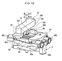
- a dial 70 is fixed to an end portion of the rotation shaft 16, and a portion of the dial 70 contacts a portion of the case 1, thereby restricting the rotation angle of the rotation shaft 16.
- the dial 70 serving as an operation means is a component with an elongated shape with length direction in the direction orthogonal to the rotation shaft 16 axial direction.
- the dial 70 is provided with an upper wall portion 70A and a lower wall portion 70B that extend in a direction substantially orthogonal to the rotation shaft 16 axial direction, and a side wall portion 70C that connects together the upper wall portion 70A and the lower wall portion 70B.
- the lower wall portion 70B is formed with a fixing hole, not illustrated in the drawings, formed to follow the profile of the end portion of the rotation shaft 16. The end portion of the rotation shaft 16 is inserted into the fixing hole, and the dial 70 is fixed to the end portion of the rotation shaft 16 using a screw, not shown in the drawings.
- the lower wall portion 70B is further provided with a substantially rectangular box shaped projection portion 72 serving as a contact portion.
- the projection portion 72 is disposed at a location adjacent to the fixing hole provided to the lower wall portion 70B. In the resulting configuration, the projection portion 72 moves so as to rotate about the rotation shaft 16.
- the faces of the projection portion 72 facing along the rotation shaft 16 circumferential direction configure a first contact face 72A and a second contact face 72B.
- a cover 80 includes a base portion 82 that covers the recessed area 2 (see Fig. 2 ) of the case 1.
- the cover 80 is further provided with a protruding portion 84 formed so as to project out from the base portion 82 in the motor shaft 21 (see Fig. 2 ) axial direction and to cover the housing portion 60 (see Fig. 2 ).
- the base portion 82 is formed with an insertion and passing hole 86 through which the rotation shaft 16 is inserted and passed.
- the base portion 82 is also provided with a first projection portion 88 and a second projection portion 90 that serve as contacted portions and are formed projecting out in the base portion 82 plate thickness direction.
- the first projection portion 88 and the second projection portion 90 are formed in substantially rectangular box shapes, and are disposed at locations adjacent to the insertion and passing hole 86. Faces of the first projection portion 88 and the second projection portion 90 facing towards the insertion and passing hole 86 side configure a first contacted face 88A and a second contacted face 90A that contact the first contact face 72A and the second contact face 72B of the projection portion 72. Attachment holes 80a are also formed to the base portion 82. Screws are inserted and passed through the attachment holes 80a and tightened in attachment holes 1b (see Fig. 2 ) formed in the case 1, thereby fixing the cover 80 to the case 1. Note that in the fixed state of the cover 80 to the case 1, the cover 80 may be regarded as forming a portion of the case 1.
Landscapes
- Engineering & Computer Science (AREA)
- General Engineering & Computer Science (AREA)
- Mechanical Engineering (AREA)
- Aviation & Aerospace Engineering (AREA)
- Transportation (AREA)
- Gear Transmission (AREA)
- Transmission Devices (AREA)
- Seats For Vehicles (AREA)
Abstract
Description
- The present invention relates to a multi-shaft drive device that is preferably applied to for example an electric vehicle seat and that drives plural output shafts with a single motor.
- Many vehicle seats are of a type enabling adjustment of position to plural locations, for example sliding the overall seat in the front-rear direction, moving the height of the seat face up and down, or reclining the seatback (backrest) to suit the build and posture of an occupant. Such adjustment of movable locations may be performed manually, however more convenient electric seats are provided that use the drive of a motor to perform adjustments.
- In order to independently drive plural respective movable locations, a configuration wherein motors are individually coupled to respective drive shafts that are each coupled to a movable location may be considered, however this would increase the number of motors. Since it is more efficient for a single motor to drive plural output shafts, proposals have been made wherein the power of a motor is transmitted through clutches to respective output shafts coupled to the plural movable locations, and each of the movable locations is selectively driven by disconnecting the clutches (see for example Patent Document 1).
- Patent Document 1: Japanese Patent Application Laid-Open (JP-A) No.
H6-156123 - However, when a selector for selecting the output shaft to which to transmit the power of the motor is configured including a rack and a pinion, it is desirable to protect the rack and the pinion from operation load input to the selector.
- In consideration of the above circumstances, an object of the present invention is to obtain a multi-shaft drive device capable of protecting a rack and pinion from operation load input to a selector.
- A multi-shaft drive device according to a first aspect includes: a single motor that is fixed to a case and that drives plural movable mechanisms mounted to a vehicle; an input side gear that is provided inside the case and that transmits power of the motor; an output side gear that is provided so as to be capable of projecting forwards and retreating with respect to the input side gear, thereby selectively enmeshing with the input side gear, and transmitting power transmitted from the input side gear to the movable mechanism; a selector that is provided with a rack to allow the selector to slide in one direction and an opposite direction to the one direction, that presses a portion of the output side gear to move the output side gear back, and that disconnects enmeshing between the output side gear and the input side gear; a rotation shaft that is provided with a pinion that enmeshes with the rack provided to the selector, the rotation shaft rotating about its axis due to operation force input to an operation means so as to slide the selector; and a restriction portion that is provided to a side of the operation means including the rotation shaft, and that restricts the rotation angle of the rotation shaft.
- According to the above aspect, operation force input into the operation means is transmitted to the rack through the pinion by turning the rotation shaft provided with the pinion using the operation means. The selector that is provided with the rack slides as a result. Further, a portion of the selector presses the portion of the output side gear due to the sliding of the selector, thereby moving the output side gear back. Enmeshing between the output side gear and the input side gear is disconnected as a result. In contrast, when the pressing of the portion of the output side gear is released due to the selector sliding in the opposite direction, the output side gear projects forwards. The output side gear enmeshes with the input side gear as a result.
- Note that were configuration to be made wherein the rotation angle of the rotation shaft was restricted by the selector contacting for example the case, operation force input into the rotation shaft would be borne by the rack and pinion. There would be a concern of damage being caused to the rack and pinion as a result. However, in the above aspect, the restriction portion that restricts the rotation angle of the rotation shaft is provided to the side of the operation means including the rotation shaft. Such a configuration accordingly prevents operation force input into the rotation shaft from being borne by the rack and pinion such as occurs in a configuration wherein the rotation angle of the rotation shaft is restricted by the selector contacting for example the case.
- A multi-shaft drive device according to a second aspect is the first aspect, wherein the restriction portion includes: the operation means fixed to the rotation shaft; and a contacted portion that is provided to the case and is contacted by a portion of the operation means.
- According to the above aspect, operation force input into the rotation shaft is borne by the portion of the operation means contacting the contacted portion provided to the case. As a result, operation force input into the rotation shaft is prevented from being borne directly by the rack and pinion.
- A multi-shaft drive device according to a third aspect is the first aspect, wherein the restriction portion includes: a contact portion that is provided inside the case and that is formed to a portion of the rotation shaft; and a contacted portion that is provided to the case and that is contacted by the contact portion.
- According to the above aspect, operation force input into the rotation shaft is borne by the contact portion formed to a portion of the rotation shaft contacting the contacted portion provided to the case. The contact portion and the contacted portion are provided inside the case of the multi-shaft drive device, thereby suppressing any impact on the external design of the multi-shaft drive device as a result of providing the contact portion and the contacted portion.
- The multi-shaft drive device according to the first aspect and the second aspect described above exhibits the excellent advantageous effect of being capable of protecting the rack and pinion from operation load input to the selector.
- The multi-shaft drive device of the third aspect exhibits the excellent advantageous effect of being capable of protecting the rack and pinion from operation force input to the selector without imposing restrictions on the external design of the multi-shaft drive device.
-
-
Fig. 1 is a perspective view illustrating a multi-shaft drive device according to an exemplary embodiment. -
Fig. 2 is a plan view illustrating the multi-shaft drive device. -
Fig. 3 is a perspective view illustrating movable portions of the multi-shaft drive device. -
Fig. 4 is a plan view illustrating the movable portions. -
Fig. 5A is a perspective view illustrating an output portion of a multi-shaft drive device of an exemplary embodiment. -
Fig. 5B is a cross-section illustrating an output portion of a multi-shaft drive device of an exemplary embodiment. -
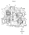
Fig. 6 is a plan view of the multi-shaft drive device. -
Fig. 7A is a perspective view illustrating a multi-shaft drive device according to a modified example. -
Fig. 7B is a perspective view illustrating a multi-shaft drive device according to a modified example. - Explanation follows regarding a multi-shaft drive device according to an exemplary embodiment that drives an electric seat in a vehicle, with reference to the drawings.
-
Fig. 1 andFig. 2 are a perspective view and a plan view illustrating a multi-shaft drive device according to an exemplary embodiment.Fig. 1 andFig. 2 illustrate acase 1 including arecessed area 2 that opens upwards, aselector 10 housed in therecessed area 2 of thecase 1, and amotor 20 fixed to a lower portion of thecase 1. The opening of therecessed area 2 of thecase 1 is covered by a cover, not illustrated in the drawings, that is fixed to thecase 1. Theselector 10 is a substantially rectangular plate shaped member that is long in the Y direction inFig. 2 , and is formed with twoguide holes 19 that extend in the Y direction at a width direction (X direction) central portion.Guide projections 3 that project out from a bottom portion of therecessed area 2 are respectively inserted into theguide holes 19. Theselector 10 is supported so as to be capable of sliding in the Y direction with theguide holes 19 guided by theguide projections 3. - Out of the two length direction side faces of the
selector 10, the side face on the right hand side inFig. 2 is formed with afirst cam face 11. The side face on the left hand side is formed with asecond cam face 12 at a lower side and formed with arack 18 with a row of teeth running in the Y direction at an upper side. - As illustrated in
Fig. 2 , arotation shaft 16 that is rotatably supported on thecase 1 is provided with apinion 17 formed so as to extend towards therotation shaft 16 radial direction outside. Thepinion 17 is formed around the circumferential direction of therotation shaft 16, withcontact portions 17A configured at both circumferential direction end portions of thepinion 17, and thecontact portion 17A contacts avertical wall portion 1A of thecase 1 that forms therecessed area 2 and serves as a contacted portion. The rotation angle of therotation shaft 16 is restricted due to thecontact portions 17A contacting thevertical wall portion 1A. Thepinion 17 is enmeshed with therack 18. Further, adial 69 serving as an operation means is fixed to therotation shaft 16. Thepinion 17 rotates when thedial 69 is rotated, thereby moving theselector 10 back and forth along the Y direction through therack 18 according to the rotation direction of thedial 69. - As illustrated in
Fig. 3 and Fig. 4 ,output portions 30 are disposed facing each of thecam faces selector 10. In the present example, two output portions 30 (afirst output portion 30A and asecond output portion 30B) are disposed separated from each other in the Y direction and facing thefirst cam face 11, and one output portion 30 (athird output portion 30C) is disposed facing thesecond cam face 12. Theoutput portions 30 are housed inhousing portions 60 formed to thecase 1 as illustrated inFig. 1 andFig. 2 . - As illustrated in
Fig. 2 andFig. 4 , amotor shaft 21 of themotor 20 projects upwards. Themotor shaft 21 can be rotated forwards or in reverse. Apinion 22 is fixed to themotor shaft 21. Three input sideclutch members 50 corresponding to therespective output portions 30 are provided to the periphery of thepinion 22 and are rotatably supported on thecase 1. Each of the input sideclutch members 50 is of a similar configuration, and includes aninput gear 51 that enmeshes with thepinion 22 configured by a flattened cog, and an inputside bevel gear 52 serving as an input side gear integrally formed to an upper face of theinput gear 51. The input side bevel gears 52 are rotatably supported on thecase 1 for each of the input sideclutch members 50, thereby positioning the input sideclutch members 50 at specific positions. Themotor 20 is switched ON/OFF, and the rotation direction thereof is selected, for example by a switch provided to thedial 69. When themotor 20 is actuated, all of the input sideclutch members 50 rotate. - Each of the output portions 30 (30A to 30C) are of similar configuration. As illustrated in
Fig. 4 ,Fig. 5A and Fig. 5B , theoutput portions 30 are configured including anoutput shaft 31 disposed in a state facing the cam face 11 (12), an output sideclutch member 32 provided so as to be capable of rotating together as a unit with theoutput shaft 31, and also capable of projecting forwards or retreating along theoutput shaft 31 axial direction with respect to the cam face 11 (12), and acoil spring 36 that biases the output sideclutch member 32 so as to project forwards towards the inputside bevel gear 52. - The
output shafts 31 are rotatably supported bysupport portions 61 configuring thehousing portions 60 of thecase 1. Theoutput shafts 31 are respectively connected through torque cables, not illustrated in the drawings, to movable mechanisms provided to an electric seat in a vehicle, for example, a mechanism for adjusting the height of a seat face, a reclining mechanism for adjusting the angle of the seatback (backrest portion), and a mechanism for adjusting the front-rear position of the seat. One end portions of the torque cables are inserted into mountingholes 31b (seeFig. 1 ) of rectangular cross-section profile that are formed to rear end faces of theoutput shafts 31, and rotate together with theoutput shafts 31. - As illustrated in
Fig. 5A and Fig. 5B , the output sideclutch members 32 are each configured including: a circular cylinder shapedslide shaft 33 that is externally mounted to theselector 10 side of theoutput shaft 31; an outputside bevel gear 34 serving as an output side gear that has a toothed face integrally formed to a leading end side of theslide shaft 33 facing towards theselector 10 side; a pin (contact portion) 35 that projects out in the axial direction from the center of the outputside bevel gear 34; and thecoil spring 36 that biases theslide shaft 33 in the direction of theselector 10. - An inner peripheral face of the
slide shaft 33 is not capable of relative rotation in the circumferential direction with respect to the outer peripheral face of theoutput shaft 31, namely theslide shaft 33 is capable of rotating as a unit together with theoutput shaft 31, and the two are spline joined together so as to allow sliding along the axial direction. Theslide shafts 33 are accordingly capable of projecting forwards or retreating in theoutput shaft 31 axial direction with respect to the cam faces. Thecoil spring 36 is housed inside theoutput shaft 31 and theslide shaft 33 in a compressed state, and biases theslide shaft 33 from theoutput shaft 31 towards the cam faces 11 (12). Leading ends of thepins 35 of the output sideclutch members 32 accordingly abut the cam faces 11 (12) when facing the cam faces 11 (12). Leading end faces of thepins 35 are formed with spherical face shapes, and make sliding contact with the abutting cam faces 11 (12) when theselector 10 is moved in the Y direction by thedial 69 described above. - The
first cam face 11 of theselector 10 is formed with a first recessedportion 13A and a second recessedportion 13B serving as cam portions corresponding to thefirst output portion 30A and thesecond output portion 30B, and thesecond cam face 12 is formed with a third recessedportion 13C serving as a cam portion corresponding to thethird output portion 30C. When theselector 10 is operated so as to move along the Y direction as described above, thepin 35 of any one of theoutput portions 30 faces the corresponding recessedportion 13A (13B, 13C). The output sideclutch member 32 is biased as a whole towards the cam face 11 (12) by thecoil spring 36, such that thepin 35 projects out and fits into the recessedportion 13A (13B, 13C). - The output side
clutch member 32 slides as a whole in theselector 10 direction when thepin 35 projects out and fits into the recessedportion 13A (13B, 13C), and the outputside bevel gear 34 enmeshes with the inputside bevel gear 52, achieving a clutch connected state. When themotor 20 is actuated and the input sideclutch member 50 rotates with the clutch connected, the rotation is transmitted from the inputside bevel gear 52 to the enmeshed outputside bevel gear 34, and the overall output sideclutch member 32 rotates. The rotation of theslide shaft 33 is transmitted to theoutput shaft 31 and theoutput shaft 31 rotates, thereby rotating and actuating the torque cable. When thepin 35 is not in a state facing the recessedportion 13A (13B, 13C), thepin 35 contacts the cam face 11 (12) at a portion other than the recessedportion 13A (13B, 13C), the cam face 11 (12) pressing thepin 35 towards theoutput shaft 31 side against thecoil spring 36. When this occurs, the outputside bevel gear 34 separates from the inputside bevel gear 52 to achieve a clutch disconnected state. - The
housing portions 60 of thecase 1 in which therespective output portions 30 are housed are each formed so as to enclose the respective output sideclutch member 32 and include: the circular cylinder shapedsupport portion 61 that is positioned to a rear portion side of theoutput portion 30 and that rotatably supports theoutput shaft 31 in a state restricting movement towards the rear and away from theselector 10; a leadingend wall portion 62 positioned at theoutput portion 30 leading end side; and a pair ofside wall portions 63 that are integrally formed with thesupport portion 61 and the leadingend wall portion 62 so as to couple together thesupport portion 61 and the leadingend wall portion 62, and formed to both sides of the output sideclutch member 32 including the outputside bevel gear 34. Thesupport portion 61, the leadingend wall portion 62 and the pair ofside wall portions 63 are integrally formed to thecase 1. - The leading
end wall portion 62 is formed with a throughhole 62a that is rotatably penetrated by thepin 35. Each of theoutput portions 30 is inserted inside thecorresponding housing portion 60 with thecoil spring 36 compressed to a contracted state such that the output sideclutch member 32 and theoutput shaft 31 mutually approach each other, with thepin 35 passed through the throughhole 62a of the leadingend wall portion 62 from an upper portion opening. Next, the force from compression is released, and theoutput shaft 31 is inserted inside thesupport portion 61, thereby assembling theoutput portion 30 inside thehousing portion 60. - The
output shaft 31 of theoutput portion 30 that has been thus assembled inside thehousing portion 60 is rotatably supported by thesupport portion 61. Thepin 35 penetrates the throughhole 62a such that both end portions of theoutput portion 30 are in a rotabably supported state. When the output sideclutch member 32 that is biased in theselector 10 direction by thecoil spring 36 is in the clutch connected state wherein thepin 35 is fitted into any one of the recessedportions 13A to 13C of theselector 10 and projecting forwards in theselector 10 direction, a leading end face of the outputside bevel gear 34 contacts an inner face of the leadingend wall portion 62, restricting projection any further forwards towards theselector 10 side. - At this time, in the clutch connected state in which the output
side bevel gear 34 is enmeshed with the inputside bevel gear 52, setting is made to position the axial direction position of the outputside bevel gear 34 at an appropriate enmeshing position with the inputside bevel gear 52 due to the leading end face of the outputside bevel gear 34 contacting the inner face of the leadingend wall portion 62. Moreover, in the clutch disconnected state in which thepin 35 is pressed by the cam faces 11, 12 of theselector 10 and the outputside bevel gear 34 has separated from the inputside bevel gear 52, the leading end face of the outputside bevel gear 34 separates from the inner face of the leadingend wall portion 62. - Explanation follows regarding operation of the multi-shaft drive device described above.
-
Fig. 2 andFig. 4 illustrate a state in which thedial 69 has been rotated (therotation shaft 16 has been rotated in a C1 direction), moving theselector 10 in the Y direction, and thepin 35 of the output sideclutch member 32 of thefirst output portion 30A is projecting out and fitting into the first recessedportion 13A. Here, the outputside bevel gear 34 of thefirst output portion 30A is enmeshed with the inputside bevel gear 52 corresponding to thefirst output portion 30A, achieving the clutch connected state. In the other output portions 30 (thesecond output portion 30 and the third output portion 30), thepins 35 are pressed by the cam faces 11, 12 and the output side bevel gears 34 are separated from the corresponding input side bevel gears 52. In this state, one of the end portions (thecontact portions 17A) of thepinion 17 provided to therotation shaft 16 is in contact with thevertical wall portion 1A of thecase 1. Further rotation of therotation shaft 16 in the C1 direction is accordingly restricted. - When the
dial 69 is rotated (therotation shaft 16 is rotated in a C2 direction) from this state to move the selector 10 a specific distance in the Y1 direction, thepin 35 of thesecond output portion 30B projects out and fits into the second recessedportion 13B, and the outputside bevel gear 34 of thesecond output portion 30B enmeshes with the corresponding inputside bevel gear 52, to achieve a clutch connected state. When this occurs, in the other output portions 30 (thefirst output portion 30A and thethird output portion 30C), thepins 35 are pressed by the cam faces 11, 12, and the output side bevel gears 34 separate from the corresponding inputside bevel gears 52 to achieve a clutch disconnected state. - Further, as illustrated in
Fig. 6 , when thedial 69 is rotated (therotation shaft 16 is rotated in the C2 direction) to move the selector 10 a specific distance in the Y1 direction, thepin 35 of thethird output portion 30C projects out and fits into the third recessedportion 13C, and the outputside bevel gear 34 of thethird output portion 30C enmeshes with the corresponding inputside bevel gear 52, to achieve a clutch connected state. When this occurs, in the other output portions 30 (thefirst output portion 30A and thesecond output portion 30B), thepins 35 are pressed by thecam face 11, and the output side bevel gears 34 separate from the corresponding inputside bevel gears 52 to achieve a clutch disconnected state. In this state, the other end portion (contact portion 17A) of thepinion 17 provided to therotation shaft 16 is in contact with thevertical wall portion 1A of thecase 1. Further rotation of therotation shaft 16 in the C2 direction is accordingly restricted. - The
selector 10 moves back and forth in the Y direction with forward and reverse rotation of thedial 69. Along the path of this movement, thepins 35 project out and fit into any one of the recessedportions 13A to 13C of theselector 10, and when this occurs, one of theoutput portions 30 out of the first tothird output portions 30A to 30C is selected as described above. The outputside bevel gear 34 of the selectedoutput portion 30 enmeshes with the corresponding inputside bevel gear 52 to achieve the clutch connected state. - In this clutch connected state, when the switch is switched ON and the
motor 20 is actuated, the power of themotor 20 is transmitted from the inputside bevel gear 52 to the outputside bevel gear 34, rotating the overall output sideclutch member 32, and thereby rotating theoutput shaft 31. The torque cable connected to theoutput shaft 31 of the selectedoutput portion 30 accordingly rotates, achieving an actuated state. The rotation direction of theoutput shafts 31 and the torque cables can be switched by switching the rotation direction of themotor 20 using the switch. - According to the exemplary embodiment described above, the end portions (
contact portions 17A) of thepinion 17 and thevertical wall portion 1A of thecase 1 are provided to serve as restriction portions that restrict the rotation angle of therotation shaft 16. Operation force input into the rotation shaft is accordingly prevented from being borne directly by therack 18 and thepinion 17. As a result, in the present exemplary embodiment it is possible to prevent damage to therack 18 and thepinion 17 due to operation load input into theselector 10 from therotation shaft 16. - According to the exemplary embodiment described above, the
respective output portions 30 are housed in thehousing portions 60 formed to thecase 1. In this housed state, the output side bevel gears 34 of the output sideclutch members 32 that are biased in the direction of the input side bevel gears 52 by the coil springs 36 are enclosed by thesupport portions 61, the leadingend wall portions 62 and the pairs ofside wall portions 63 integrally formed to thecase 1. When in the clutch connected state, the leading end faces of the output side bevel gears 34 contact the leadingend wall portions 62, thereby restricting the axial direction position of the output side bevel gears 34 such that the output side bevel gears 34 always enmesh appropriately with the input side bevel gears 52. - The leading
end wall portions 62 are pressed by the output side bevel gears 34 biased by the coil springs 36, however since the leadingend wall portions 62 are integrally formed to thecase 1 together with thesupport portions 61 and the pairs ofwall portions 63, stress received due to this pushing is not concentrated on the leadingend wall portions 62 and is distributed around theoverall case 1 through thesupport portions 61 and the pairs ofwall portions 63, thereby enabling deformation of the leadingend wall portions 62 to be suppressed. The axial direction positions of the output side bevel gears 34 can accordingly be reliably positioned at uniform positions due to contacting the leadingend wall portions 62. Moreover, in the present exemplary embodiment the input side bevel gears 52 are also supported and positioned by thecase 1 similarly to the output side bevel gears 34, such that relative positional displacement between the two does not readily occur. Backlash can therefore always be stabilized with a high degree of precision in the enmeshed state of the output side bevel gears 34 with the input side bevel gears 52. The advantageous effects that tooth end bearing of the output side bevel gears 34 with respect to the input side bevel gears 52 can be suppressed, increasing durability, and enabling as a result a reduction in operation noise occurring during enmeshing to be obtained. - Note that in the above exemplary embodiment, the
selector 10 of the present invention is configured so as to move along a straight line, however modification may be made to the present invention such that theselector 10 is a circular plate shaped rotating member with the peripheral face configuring the cam face, wherein theplural output portions 30 are disposed to the periphery of the cam face. - Explanation follows regarding a modified example of the above exemplary embodiment with reference to
Fig. 7A andFig. 7B . - Note that members similar to those of the above exemplary embodiment are allocated the same reference numerals and explanation thereof is omitted.
- In the multi-shaft drive device according to the present modified example, a
dial 70 is fixed to an end portion of therotation shaft 16, and a portion of thedial 70 contacts a portion of thecase 1, thereby restricting the rotation angle of therotation shaft 16. - Specifically, the
dial 70 serving as an operation means is a component with an elongated shape with length direction in the direction orthogonal to therotation shaft 16 axial direction. Thedial 70 is provided with anupper wall portion 70A and alower wall portion 70B that extend in a direction substantially orthogonal to therotation shaft 16 axial direction, and aside wall portion 70C that connects together theupper wall portion 70A and thelower wall portion 70B. Thelower wall portion 70B is formed with a fixing hole, not illustrated in the drawings, formed to follow the profile of the end portion of therotation shaft 16. The end portion of therotation shaft 16 is inserted into the fixing hole, and thedial 70 is fixed to the end portion of therotation shaft 16 using a screw, not shown in the drawings. Thelower wall portion 70B is further provided with a substantially rectangular box shapedprojection portion 72 serving as a contact portion. Theprojection portion 72 is disposed at a location adjacent to the fixing hole provided to thelower wall portion 70B. In the resulting configuration, theprojection portion 72 moves so as to rotate about therotation shaft 16. The faces of theprojection portion 72 facing along therotation shaft 16 circumferential direction configure afirst contact face 72A and asecond contact face 72B. - A
cover 80 includes abase portion 82 that covers the recessed area 2 (seeFig. 2 ) of thecase 1. Thecover 80 is further provided with a protrudingportion 84 formed so as to project out from thebase portion 82 in the motor shaft 21 (seeFig. 2 ) axial direction and to cover the housing portion 60 (seeFig. 2 ). Thebase portion 82 is formed with an insertion and passinghole 86 through which therotation shaft 16 is inserted and passed. Thebase portion 82 is also provided with afirst projection portion 88 and asecond projection portion 90 that serve as contacted portions and are formed projecting out in thebase portion 82 plate thickness direction. Thefirst projection portion 88 and thesecond projection portion 90 are formed in substantially rectangular box shapes, and are disposed at locations adjacent to the insertion and passinghole 86. Faces of thefirst projection portion 88 and thesecond projection portion 90 facing towards the insertion and passinghole 86 side configure a first contactedface 88A and a second contactedface 90A that contact thefirst contact face 72A and thesecond contact face 72B of theprojection portion 72.Attachment holes 80a are also formed to thebase portion 82. Screws are inserted and passed through the attachment holes 80a and tightened inattachment holes 1b (seeFig. 2 ) formed in thecase 1, thereby fixing thecover 80 to thecase 1. Note that in the fixed state of thecover 80 to thecase 1, thecover 80 may be regarded as forming a portion of thecase 1. - When the
dial 70 is rotated in the direction of the arrow C2 in order to select the output portion 30 (30A, 30B, 30C) to which the power of themotor 20 is to be transmitted, thefirst contact face 72A of theprojection portion 72 provided to thedial 70 contacts the first contactedface 88A of thefirst projection portion 88 provided to thecover 80. Further rotation of thedial 70 in the arrow C2 direction is accordingly restricted. When thedial 70 is rotated in the direction of the arrow C1, thesecond contact face 72B of theprojection portion 72 provided to thedial 70 contacts the second contactedface 90A of thesecond projection portion 90 provided to thecover 80. Further rotation of thedial 70 in thearrow C 1 direction is accordingly restricted. As a result, in the present exemplary embodiment damage to therack 18 and thepinion 17 due to operation load input from thedial 70, through therotation shaft 16, and into theselector 10 can be prevented. - Note that in the exemplary embodiment and the modified example described above, explanation has been given of an example wherein the
contact portion 17A provided to therotation shaft 16 contacts thevertical wall portion 1A of thecase 1 to configure the restriction portion that restricts the rotation angle of therotation shaft 16, and of an example wherein a portion of thedial 70 contacts the projection portions (first projection portion 88, second projection portion 90) of thecover 80 fixed to thecase 1 to configure the restriction portion that restricts the rotation angle of therotation shaft 16, however the present invention is not limited thereto. For example, in cases in which therotation shaft 16 is rotated through plural gears or the like, configuration may be made wherein a restriction portion is provided to these plural gears. The location to which the restriction portion is provided may accordingly be set as appropriate in consideration of the configuration of the operation means connected to therotation shaft 16. - Explanation has been given above of an exemplary embodiment and a modified example of the present invention, however the present invention is not limited to the above, and obviously various modifications other than those described above may be implemented within a range not departing from the spirit of the present invention.
Claims (3)
- A multi-shaft drive device comprising:a single motor that is fixed to a case and that drives a plurality of movable mechanisms mounted to a vehicle;an input side gear that is provided inside the case and that transmits power of the motor;an output side gear that is provided so as to be capable of projecting forwards and retreating with respect to the input side gear, thereby selectively enmeshing with the input side gear, and transmitting power transmitted from the input side bevel gear to the movable mechanism;a selector that is provided with a rack to allow the selector to slide in one direction and an opposite direction to the one direction, that presses a portion of the output side gear to move the output side gear back, and that disconnects enmeshing between the output side gear and the input side gear;a rotation shaft that is provided with a pinion that enmeshes with the rack provided to the selector, the rotation shaft rotating about its axis due to operation force input to an operation means so as to slide the selector; anda restriction portion that is provided to a side of the operation means including the rotation shaft, and that restricts the rotation angle of the rotation shaft.
- The multi-shaft drive device of claim 1, wherein the restriction portion comprises:the operation means fixed to the rotation shaft; anda contacted portion that is provided to the case and is contacted by a portion of the operation means.
- The multi-shaft drive device of claim 1, wherein the restriction portion comprises:a contact portion that is provided inside the case and that is formed to a portion of the rotation shaft; anda contacted portion that is provided to the case and that is contacted by the contact portion.
Applications Claiming Priority (2)
| Application Number | Priority Date | Filing Date | Title |
|---|---|---|---|
| JP2011042118 | 2011-02-28 | ||
| PCT/JP2012/051458 WO2012117771A1 (en) | 2011-02-28 | 2012-01-24 | Multi-shaft drive device |
Publications (3)
| Publication Number | Publication Date |
|---|---|
| EP2682641A1 true EP2682641A1 (en) | 2014-01-08 |
| EP2682641A8 EP2682641A8 (en) | 2014-03-12 |
| EP2682641A4 EP2682641A4 (en) | 2017-06-28 |
Family
ID=46757713
Family Applications (1)
| Application Number | Title | Priority Date | Filing Date |
|---|---|---|---|
| EP12752273.8A Withdrawn EP2682641A4 (en) | 2011-02-28 | 2012-01-24 | Multi-shaft drive device |
Country Status (6)
| Country | Link |
|---|---|
| US (1) | US9267589B2 (en) |
| EP (1) | EP2682641A4 (en) |
| JP (1) | JP5797734B2 (en) |
| KR (1) | KR101825774B1 (en) |
| CN (1) | CN103384782B (en) |
| WO (1) | WO2012117771A1 (en) |
Cited By (1)
| Publication number | Priority date | Publication date | Assignee | Title |
|---|---|---|---|---|
| CZ306544B6 (en) * | 2016-01-03 | 2017-03-01 | České vysoké učení technické v Praze, Fakulta strojní, Ústav výrobních strojů a zařízení | Drive of tension belts, especially a vertical packaging machine |
Families Citing this family (8)
| Publication number | Priority date | Publication date | Assignee | Title |
|---|---|---|---|---|
| JP6720829B2 (en) | 2016-10-26 | 2020-07-08 | トヨタ紡織株式会社 | Seat drive |
| JP6753320B2 (en) * | 2017-01-19 | 2020-09-09 | トヨタ紡織株式会社 | Seat drive |
| JP6903259B2 (en) * | 2017-05-01 | 2021-07-14 | 周浩 李 | Transmission device and method |
| US10738866B2 (en) * | 2018-04-19 | 2020-08-11 | Robert Bosch Mexico Sistemas Automotrices S.A. de C.V. | Modular actuator for providing relative motion between two points |
| US11602337B2 (en) | 2019-04-24 | 2023-03-14 | Nuvasive, Inc. | Transmission assembly |
| CN110081132A (en) * | 2019-05-30 | 2019-08-02 | 新乡北方车辆仪表有限公司 | A kind of three tunnels output transfer case |
| US11547395B2 (en) | 2019-06-18 | 2023-01-10 | Nuvasive, Inc. | Tissue retraction system |
| US11253243B2 (en) | 2019-06-18 | 2022-02-22 | Nuvasive, Inc. | Tissue retraction system |
Family Cites Families (15)
| Publication number | Priority date | Publication date | Assignee | Title |
|---|---|---|---|---|
| US2674182A (en) * | 1950-06-22 | 1954-04-06 | Joseph W Kirkpatrick | Fruit juice extractor |
| US2845807A (en) * | 1953-08-10 | 1958-08-05 | Hoe & Co R | Reversing drive |
| JPS5028181U (en) * | 1973-07-10 | 1975-04-01 | ||
| JPS5441898Y2 (en) * | 1976-06-09 | 1979-12-06 | ||
| JPS5441898A (en) * | 1977-09-06 | 1979-04-03 | Mitsubishi Chem Ind Ltd | Purification of stevioside |
| DE2901208C2 (en) * | 1979-01-13 | 1984-08-09 | Keiper Automobiltechnik Gmbh & Co Kg, 5630 Remscheid | Adjustable seat, especially vehicle seat |
| US5009296A (en) * | 1986-12-24 | 1991-04-23 | Tokyo Seat Co., Ltd. | Power transmitting apparatus for use in vehicle |
| SE464287B (en) * | 1987-10-12 | 1991-04-08 | Haakansson Bengt E W | DEVICE TO REGULATE OBJECTS OF THE DRIVING ENVIRONMENT IN A VEHICLE |
| JPH06156123A (en) | 1992-11-25 | 1994-06-03 | Mitsuba Electric Mfg Co Ltd | Device for driving movable part of power seat for vehicle |
| US6050641A (en) | 1996-12-20 | 2000-04-18 | Schukra Of North America, Ltd. | Four-way power lumbar system |
| JP4275039B2 (en) * | 2003-11-10 | 2009-06-10 | 株式会社ミツバ | Motor with reduction mechanism and power seat motor with reduction mechanism |
| JP2005145308A (en) * | 2003-11-17 | 2005-06-09 | Kiyotaka Hyodo | Outboard motor |
| JP4313280B2 (en) * | 2003-11-28 | 2009-08-12 | アスモ株式会社 | Seat driving motor and power seat device |
| JP2011021679A (en) * | 2009-07-15 | 2011-02-03 | Nhk Spring Co Ltd | Clutch device |
| JP2011031733A (en) * | 2009-07-31 | 2011-02-17 | Imasen Electric Ind Co Ltd | Reclining drive device for electric seat for vehicle |
-
2012
- 2012-01-24 WO PCT/JP2012/051458 patent/WO2012117771A1/en not_active Ceased
- 2012-01-24 CN CN201280010504.0A patent/CN103384782B/en not_active Expired - Fee Related
- 2012-01-24 EP EP12752273.8A patent/EP2682641A4/en not_active Withdrawn
- 2012-01-24 US US14/001,671 patent/US9267589B2/en active Active
- 2012-01-24 JP JP2013502212A patent/JP5797734B2/en active Active
- 2012-01-24 KR KR1020137025517A patent/KR101825774B1/en not_active Expired - Fee Related
Non-Patent Citations (1)
| Title |
|---|
| See references of WO2012117771A1 * |
Cited By (1)
| Publication number | Priority date | Publication date | Assignee | Title |
|---|---|---|---|---|
| CZ306544B6 (en) * | 2016-01-03 | 2017-03-01 | České vysoké učení technické v Praze, Fakulta strojní, Ústav výrobních strojů a zařízení | Drive of tension belts, especially a vertical packaging machine |
Also Published As
| Publication number | Publication date |
|---|---|
| KR20140010108A (en) | 2014-01-23 |
| WO2012117771A1 (en) | 2012-09-07 |
| EP2682641A4 (en) | 2017-06-28 |
| JPWO2012117771A1 (en) | 2014-07-07 |
| CN103384782A (en) | 2013-11-06 |
| CN103384782B (en) | 2016-01-20 |
| JP5797734B2 (en) | 2015-10-21 |
| US20130327181A1 (en) | 2013-12-12 |
| KR101825774B1 (en) | 2018-02-05 |
| US9267589B2 (en) | 2016-02-23 |
| EP2682641A8 (en) | 2014-03-12 |
Similar Documents
| Publication | Publication Date | Title |
|---|---|---|
| US9267589B2 (en) | Multi-shaft drive device | |
| KR101498401B1 (en) | Power transmission mechanism and multi-shaft drive device | |
| US9121482B2 (en) | Multi-shaft drive device | |
| US9388891B2 (en) | Multi-shaft drive device | |
| JP5318935B2 (en) | Multi-axis drive | |
| CN103249964B (en) | Output block and Multi-shaft drive device | |
| JP2012177459A (en) | Multi-shaft driving device | |
| JP2012177460A (en) | Bevel gear, power transmission mechanism, and multishaft driving device | |
| JP2012180852A (en) | Multi-axis driving device | |
| JP2012180850A (en) | Power transmission mechanism and multi-shaft drive unit | |
| WO2011007791A1 (en) | Clutch device | |
| JP2018134985A (en) | Seat drive device |
Legal Events
| Date | Code | Title | Description |
|---|---|---|---|
| PUAI | Public reference made under article 153(3) epc to a published international application that has entered the european phase |
Free format text: ORIGINAL CODE: 0009012 |
|
| 17P | Request for examination filed |
Effective date: 20130905 |
|
| AK | Designated contracting states |
Kind code of ref document: A1 Designated state(s): AL AT BE BG CH CY CZ DE DK EE ES FI FR GB GR HR HU IE IS IT LI LT LU LV MC MK MT NL NO PL PT RO RS SE SI SK SM TR |
|
| RIN1 | Information on inventor provided before grant (corrected) |
Inventor name: IINO, SHINJI Inventor name: NAKAYAMA, SOICHI Inventor name: HIRATA, TAKAFUMI Inventor name: KATSUBE, KENICHI Inventor name: ODA, MASAHIRO Inventor name: NAKAMURA, TAKESHI Inventor name: SHIGEMATSU, RYOHEI |
|
| DAX | Request for extension of the european patent (deleted) | ||
| RAP1 | Party data changed (applicant data changed or rights of an application transferred) |
Owner name: NHK SPRING CO., LTD. |
|
| RA4 | Supplementary search report drawn up and despatched (corrected) |
Effective date: 20170529 |
|
| RIC1 | Information provided on ipc code assigned before grant |
Ipc: F16D 125/28 20120101ALI20170522BHEP Ipc: F16D 23/12 20060101ALI20170522BHEP Ipc: B60N 2/02 20060101ALI20170522BHEP Ipc: F16H 37/06 20060101ALI20170522BHEP Ipc: F16H 25/18 20060101ALI20170522BHEP Ipc: F16H 19/04 20060101ALI20170522BHEP Ipc: F16H 3/22 20060101ALI20170522BHEP Ipc: F16H 21/28 20060101ALI20170522BHEP Ipc: F16H 1/22 20060101AFI20170522BHEP |
|
| STAA | Information on the status of an ep patent application or granted ep patent |
Free format text: STATUS: THE APPLICATION IS DEEMED TO BE WITHDRAWN |
|
| 18D | Application deemed to be withdrawn |
Effective date: 20180103 |