EP2682640A1 - Multi-shaft drive device - Google Patents
Multi-shaft drive device Download PDFInfo
- Publication number
- EP2682640A1 EP2682640A1 EP12751891.8A EP12751891A EP2682640A1 EP 2682640 A1 EP2682640 A1 EP 2682640A1 EP 12751891 A EP12751891 A EP 12751891A EP 2682640 A1 EP2682640 A1 EP 2682640A1
- Authority
- EP
- European Patent Office
- Prior art keywords
- shaft
- output
- worm
- gear
- drive device
- Prior art date
- Legal status (The legal status is an assumption and is not a legal conclusion. Google has not performed a legal analysis and makes no representation as to the accuracy of the status listed.)
- Withdrawn
Links
- 230000007246 mechanism Effects 0.000 claims abstract description 80
- 230000005540 biological transmission Effects 0.000 claims abstract description 66
- 230000002093 peripheral effect Effects 0.000 claims description 57
- 238000003780 insertion Methods 0.000 claims description 33
- 230000037431 insertion Effects 0.000 claims description 33
- 230000009467 reduction Effects 0.000 description 11
- 230000004048 modification Effects 0.000 description 9
- 238000012986 modification Methods 0.000 description 9
- 150000001875 compounds Chemical class 0.000 description 5
- 230000000694 effects Effects 0.000 description 4
- 238000004519 manufacturing process Methods 0.000 description 3
- 230000006872 improvement Effects 0.000 description 2
- 230000008901 benefit Effects 0.000 description 1
- 238000000034 method Methods 0.000 description 1
- 230000008569 process Effects 0.000 description 1
- 230000000717 retained effect Effects 0.000 description 1
Images





Classifications
-
- F—MECHANICAL ENGINEERING; LIGHTING; HEATING; WEAPONS; BLASTING
- F16—ENGINEERING ELEMENTS AND UNITS; GENERAL MEASURES FOR PRODUCING AND MAINTAINING EFFECTIVE FUNCTIONING OF MACHINES OR INSTALLATIONS; THERMAL INSULATION IN GENERAL
- F16H—GEARING
- F16H1/00—Toothed gearings for conveying rotary motion
- F16H1/02—Toothed gearings for conveying rotary motion without gears having orbital motion
- F16H1/04—Toothed gearings for conveying rotary motion without gears having orbital motion involving only two intermeshing members
- F16H1/12—Toothed gearings for conveying rotary motion without gears having orbital motion involving only two intermeshing members with non-parallel axes
- F16H1/16—Toothed gearings for conveying rotary motion without gears having orbital motion involving only two intermeshing members with non-parallel axes comprising worm and worm-wheel
-
- F—MECHANICAL ENGINEERING; LIGHTING; HEATING; WEAPONS; BLASTING
- F16—ENGINEERING ELEMENTS AND UNITS; GENERAL MEASURES FOR PRODUCING AND MAINTAINING EFFECTIVE FUNCTIONING OF MACHINES OR INSTALLATIONS; THERMAL INSULATION IN GENERAL
- F16H—GEARING
- F16H19/00—Gearings comprising essentially only toothed gears or friction members and not capable of conveying indefinitely-continuing rotary motion
- F16H19/08—Gearings comprising essentially only toothed gears or friction members and not capable of conveying indefinitely-continuing rotary motion for interconverting rotary motion and oscillating motion
-
- B—PERFORMING OPERATIONS; TRANSPORTING
- B60—VEHICLES IN GENERAL
- B60N—SEATS SPECIALLY ADAPTED FOR VEHICLES; VEHICLE PASSENGER ACCOMMODATION NOT OTHERWISE PROVIDED FOR
- B60N2/00—Seats specially adapted for vehicles; Arrangement or mounting of seats in vehicles
- B60N2/02—Seats specially adapted for vehicles; Arrangement or mounting of seats in vehicles the seat or part thereof being movable, e.g. adjustable
-
- B—PERFORMING OPERATIONS; TRANSPORTING
- B60—VEHICLES IN GENERAL
- B60N—SEATS SPECIALLY ADAPTED FOR VEHICLES; VEHICLE PASSENGER ACCOMMODATION NOT OTHERWISE PROVIDED FOR
- B60N2/00—Seats specially adapted for vehicles; Arrangement or mounting of seats in vehicles
- B60N2/02—Seats specially adapted for vehicles; Arrangement or mounting of seats in vehicles the seat or part thereof being movable, e.g. adjustable
- B60N2/0224—Non-manual adjustments, e.g. with electrical operation
- B60N2/02246—Electric motors therefor
-
- B—PERFORMING OPERATIONS; TRANSPORTING
- B60—VEHICLES IN GENERAL
- B60N—SEATS SPECIALLY ADAPTED FOR VEHICLES; VEHICLE PASSENGER ACCOMMODATION NOT OTHERWISE PROVIDED FOR
- B60N2/00—Seats specially adapted for vehicles; Arrangement or mounting of seats in vehicles
- B60N2/02—Seats specially adapted for vehicles; Arrangement or mounting of seats in vehicles the seat or part thereof being movable, e.g. adjustable
- B60N2/0224—Non-manual adjustments, e.g. with electrical operation
- B60N2/02246—Electric motors therefor
- B60N2/02253—Electric motors therefor characterised by the transmission between the electric motor and the seat or seat parts
-
- B—PERFORMING OPERATIONS; TRANSPORTING
- B60—VEHICLES IN GENERAL
- B60N—SEATS SPECIALLY ADAPTED FOR VEHICLES; VEHICLE PASSENGER ACCOMMODATION NOT OTHERWISE PROVIDED FOR
- B60N2/00—Seats specially adapted for vehicles; Arrangement or mounting of seats in vehicles
- B60N2/02—Seats specially adapted for vehicles; Arrangement or mounting of seats in vehicles the seat or part thereof being movable, e.g. adjustable
- B60N2/0296—Central command actuator to selectively switch on or engage one of several special purpose circuits or mechanisms
-
- F—MECHANICAL ENGINEERING; LIGHTING; HEATING; WEAPONS; BLASTING
- F16—ENGINEERING ELEMENTS AND UNITS; GENERAL MEASURES FOR PRODUCING AND MAINTAINING EFFECTIVE FUNCTIONING OF MACHINES OR INSTALLATIONS; THERMAL INSULATION IN GENERAL
- F16D—COUPLINGS FOR TRANSMITTING ROTATION; CLUTCHES; BRAKES
- F16D11/00—Clutches in which the members have interengaging parts
- F16D11/02—Clutches in which the members have interengaging parts disengaged by a contact of a part mounted on the clutch with a stationarily-mounted member
- F16D11/04—Clutches in which the members have interengaging parts disengaged by a contact of a part mounted on the clutch with a stationarily-mounted member with clutching members movable only axially
-
- F—MECHANICAL ENGINEERING; LIGHTING; HEATING; WEAPONS; BLASTING
- F16—ENGINEERING ELEMENTS AND UNITS; GENERAL MEASURES FOR PRODUCING AND MAINTAINING EFFECTIVE FUNCTIONING OF MACHINES OR INSTALLATIONS; THERMAL INSULATION IN GENERAL
- F16H—GEARING
- F16H1/00—Toothed gearings for conveying rotary motion
- F16H1/02—Toothed gearings for conveying rotary motion without gears having orbital motion
- F16H1/04—Toothed gearings for conveying rotary motion without gears having orbital motion involving only two intermeshing members
- F16H1/06—Toothed gearings for conveying rotary motion without gears having orbital motion involving only two intermeshing members with parallel axes
-
- F—MECHANICAL ENGINEERING; LIGHTING; HEATING; WEAPONS; BLASTING
- F16—ENGINEERING ELEMENTS AND UNITS; GENERAL MEASURES FOR PRODUCING AND MAINTAINING EFFECTIVE FUNCTIONING OF MACHINES OR INSTALLATIONS; THERMAL INSULATION IN GENERAL
- F16H—GEARING
- F16H1/00—Toothed gearings for conveying rotary motion
- F16H1/02—Toothed gearings for conveying rotary motion without gears having orbital motion
- F16H1/04—Toothed gearings for conveying rotary motion without gears having orbital motion involving only two intermeshing members
- F16H1/12—Toothed gearings for conveying rotary motion without gears having orbital motion involving only two intermeshing members with non-parallel axes
-
- F—MECHANICAL ENGINEERING; LIGHTING; HEATING; WEAPONS; BLASTING
- F16—ENGINEERING ELEMENTS AND UNITS; GENERAL MEASURES FOR PRODUCING AND MAINTAINING EFFECTIVE FUNCTIONING OF MACHINES OR INSTALLATIONS; THERMAL INSULATION IN GENERAL
- F16H—GEARING
- F16H37/00—Combinations of mechanical gearings, not provided for in groups F16H1/00 - F16H35/00
- F16H37/02—Combinations of mechanical gearings, not provided for in groups F16H1/00 - F16H35/00 comprising essentially only toothed or friction gearings
- F16H37/06—Combinations of mechanical gearings, not provided for in groups F16H1/00 - F16H35/00 comprising essentially only toothed or friction gearings with a plurality of driving or driven shafts; with arrangements for dividing torque between two or more intermediate shafts
-
- F—MECHANICAL ENGINEERING; LIGHTING; HEATING; WEAPONS; BLASTING
- F16—ENGINEERING ELEMENTS AND UNITS; GENERAL MEASURES FOR PRODUCING AND MAINTAINING EFFECTIVE FUNCTIONING OF MACHINES OR INSTALLATIONS; THERMAL INSULATION IN GENERAL
- F16H—GEARING
- F16H37/00—Combinations of mechanical gearings, not provided for in groups F16H1/00 - F16H35/00
- F16H37/02—Combinations of mechanical gearings, not provided for in groups F16H1/00 - F16H35/00 comprising essentially only toothed or friction gearings
- F16H37/06—Combinations of mechanical gearings, not provided for in groups F16H1/00 - F16H35/00 comprising essentially only toothed or friction gearings with a plurality of driving or driven shafts; with arrangements for dividing torque between two or more intermediate shafts
- F16H37/065—Combinations of mechanical gearings, not provided for in groups F16H1/00 - F16H35/00 comprising essentially only toothed or friction gearings with a plurality of driving or driven shafts; with arrangements for dividing torque between two or more intermediate shafts with a plurality of driving or driven shafts
-
- Y—GENERAL TAGGING OF NEW TECHNOLOGICAL DEVELOPMENTS; GENERAL TAGGING OF CROSS-SECTIONAL TECHNOLOGIES SPANNING OVER SEVERAL SECTIONS OF THE IPC; TECHNICAL SUBJECTS COVERED BY FORMER USPC CROSS-REFERENCE ART COLLECTIONS [XRACs] AND DIGESTS
- Y10—TECHNICAL SUBJECTS COVERED BY FORMER USPC
- Y10T—TECHNICAL SUBJECTS COVERED BY FORMER US CLASSIFICATION
- Y10T74/00—Machine element or mechanism
- Y10T74/18—Mechanical movements
- Y10T74/18568—Reciprocating or oscillating to or from alternating rotary
- Y10T74/188—Reciprocating or oscillating to or from alternating rotary including spur gear
Definitions
- the present invention relates to a multi-shaft drive device that is preferably provided for example to a vehicle seat and that selectively drives plural movable mechanisms with a single motor.
- the position adjustment includes, for example, sliding the overall seat in the front-rear direction, moving the height of the seat face up and down, or reclining the seatback (backrest).
- Such adjustment of the plural movable portions may be performed manually, however more convenient electric seats are provided that use the drive of a motor to perform adjustments.
- Patent Document 1 Japanese National-Phase Publication No. H3-501832
- a subject of the present invention is to provide a multi-shaft drive device capable of increasing productivity compared to previously.
- a multi-shaft drive device of a first aspect includes: an input portion to which power of a motor is transmitted; plural output portions, each of which is provided with an output shaft, the output shafts being individually connected to plural movable mechanisms; a clutch part capable of selectively disconnecting power transmission from the input portion to the plural output portions; and a gearbox that includes a power transmission member provided coaxially to the output shaft of at least one output portion out of the plural output portions, and that connects together the output shaft and the movable mechanism.
- the output shaft of at least one output portion out of the plural output portions is connected to the movable mechanism by the gearbox that includes the transmission member provided coaxially to the output shaft.
- the connection structure between the output shaft and a drive shaft of the movable mechanism can accordingly be made simpler than when employing a conventional cable for power transmission. Productivity can accordingly be increased due to assembly being made easier.
- a multi-shaft drive device of a second aspect is the first aspect, wherein the power transmission member is integrally formed with the output shaft.
- the power transmission member provided to the gearbox is integrally formed with the output shaft provided at the output portion.
- Productivity can accordingly be further increased since the number of components and the number of component assembly processes can be reduced.
- a multi-shaft drive device of a third aspect is either the first aspect or the second aspect, wherein the power transmission member includes a worm, and the gearbox includes a worm wheel that engages with the worm.
- the gearbox is configured including the worm and the worm wheel, namely including a worm gear, thereby enabling a large speed reduction ratio to be obtained in a single step by the worm gear. A reduction in the size of the device can accordingly be achieved.
- a multi-shaft drive device of a fourth aspect is any one of the first aspect to the third aspect, further including: a device case integrally provided with: a clutch unit case portion housing the plural output portions, the input portion, and a clutch unit, the clutch unit including the clutch part; and a gearbox case portion housing the gearbox.
- the device case is integrally providing with the gearbox case portion and the clutch unit case portion, the gearbox case portion housing the gearbox including the power transmission member and the clutch unit case portion housing the clutch unit.
- Productivity can accordingly be further increased since assembly can be made easy.
- a multi-shaft drive device of a fifth aspect is any one of the first aspect to the fourth aspect, wherein the clutch part includes: plural clutch mechanisms that are respectively provided to each of the plural output portions, and that disconnect power transmission from the input portion to the output shafts; and a switching part for selectively placing the plural clutch mechanisms in a connected state.
- the plural clutch mechanisms respectively provided to each of the plural output portions can be selectively placed in the connected state by the switching part, thereby enabling power transmission from the input portion to the output shaft of the selected output portion.
- a reduction in size of the configuration of each clutch mechanism is accordingly enabled due to respectively providing the clutch mechanisms to each of the plural output portions, thereby enabling a reduction in the size of the device.
- a multi-shaft drive device of a sixth aspect is the third aspect, wherein: an end portion of the worm is formed with a projection portion that is coaxial to the worm with a step portion interposed therebetween; the worm is coaxially inserted into a worm insertion hole that is formed in the gearbox case portion and that has a circular cylinder shaped inner peripheral face, and the worm is supported by a shaft bearing portion mounted in the worm insertion hole; a circular cylinder shaped face formed at an outer peripheral face of the shaft bearing portion makes contact with the inner peripheral face of the worm insertion hole, and a male thread portion formed at the outer peripheral face is screwed together with a female thread portion formed at the inner peripheral face, and the shaft bearing portion engages with the step portion in a state in which the projection portion is coaxially inserted inside the shaft bearing portion so as to be capable of sliding rotation.
- the circular cylinder face formed at the outer peripheral face of the shaft bearing portion makes contact with the circular cylinder shaped inner peripheral face of the worm insertion hole of the gearbox case portion, thereby positioning the shaft bearing portion coaxially to the worm insertion hole.
- the projection portion of the worm is inserted inside the shaft bearing portion so as to be coaxial to and capable of sliding rotation, whereby the worm is positioned with a high degree of precision in the worm radial direction.
- the step portion at the end portion of the worm engages with the shaft bearing portion, thereby positioning the worm with a high degree of precision in a worm thrust direction.
- a position in the thrust direction of the worm can be changed by adjusting an amount by which the cap is screwed into the worm insertion hole, enabling thrust direction adjustment of the worm to be performed.
- the worm can accordingly be positioned with a high degree of precision in both the thrust direction and the radial direction by employing a simple configuration.
- a multi-shaft drive device of a seventh aspect is either the third aspect or the sixth aspect, wherein: a transmission shaft is configured with the output shaft formed at one end side of the transmission shaft and the worm formed at the other end side of the transmission shaft; the output portion is further provided with a gear having a slide shaft, the gear is formed with a gear portion at a leading end portion of the slide shaft; the slide shaft of the gear is mounted to the output shaft so as to be rotatable together as a unit with the output shaft and so as to be capable of sliding in a thrust direction with respect to the output shaft; and at least two positions that are separated in the axial direction of the transmission shaft are rotatably supported through shaft bearings by the gearbox case portion, and a leading end portion and the slide shaft of the gear are rotatably supported by the gearbox case portion through shaft bearings so as to be movable along the thrust direction.
- the slide shaft of the gear provided to the output portion is mounted to the output shaft provided to the transmission shaft so as to be rotatable together as a unit with the output shaft and so as to be capable of sliding in the thrust direction with respect to the output shaft.
- the transmission shaft is rotatably supported by the gearbox case portion through the shaft bearings at least at two positions separated in the axial direction of the transmission shaft, and the leading end portion and the slide shaft of the gear are rotatably supported by the gearbox case portion through the shaft bearings so as to be movable along the thrust direction. Since the leading end portion and slide shaft of the gear that slides with respect to the output shaft (transmission shaft) are supported by the gearbox case portion through the shaft bearings, the gear can be supported with sufficient support force. As a result, support of the gear can be stabilized, thereby enabling noise generation and damage to be prevented.
- a multi-shaft drive device of an eighth aspect is the seventh aspect, wherein: an outside engagement portion formed at one, and an inside engagement portion formed at the other, of the output shaft and the slide shaft, slidably engage to each other such that the gear is mounted to the output shaft so as to be rotatable together as a unit with the output shaft and also capable of sliding in the thrust direction with respect to the output shaft, the outside engagement portion has a recessed and projected cross-section profile formed at an outer peripheral face along an axial direction of the one, and the inside engagement portion has a recessed and projected cross-section profile formed at an inner peripheral face along the axial direction of the other; and a clearance between the outside engagement portion and the inside engagement portion is set such that the slide shaft is movable in the radial direction thereof with respect to the output shaft within a preset range.
- the outside engagement portion of the output shaft and the inside engagement portion of the slide shaft of the gear engage with each other such that the gear is mounted to the output shaft so as to be capable of rotating together as a unit with the output shaft and also capable of sliding in the thrust direction with respect to the output shaft.
- the clearance between the outside engagement portion and the inside engagement portion is set such that the slide shaft, namely the gear, is movable in the radial direction thereof with respect to the output shaft within a preset range.
- the gear and the transmission shaft can be supported on the plural shaft bearings and can engage with each other so as to be both rotatable together as a unit and slidable with respect to each other in the thrust direction even when there is a low degree of coaxiality between the gear side shaft bearings and the transmission shaft side shaft bearings. Since requirements of coaxiality for the plural shaft bearings can be reduced, manufacture can be made easier, and mass productivity can be increased.
- a multi-shaft drive device of a ninth aspect is either the fifth aspect or the sixth aspect, wherein the gear is an output side bevel gear that enmeshes with an input side bevel gear provided to the input portion when the clutch part is connected.
- the output side bevel gear is mounted to the output shaft so as to be rotatable together as a unit with the output shaft and so as also be capable of sliding in the thrust direction with respect to the output shaft.
- the output side bevel gear enmeshes with the input side bevel gear provided to the input portion to place the clutch part in a connected state.
- the output side bevel gear moreover separates from the input side bevel gear to place the clutch part in a disconnected state.
- the clutch part can be connected or disconnected by projecting forward or retreating the output side bevel gear with respect to the input side bevel gear, thereby enabling the clutch art to be achieved with a simple configuration.
- a multi-shaft drive device of a tenth aspect is any one of the first aspect to the ninth aspect, wherein the movable mechanisms actuate movable locations of a vehicle seat.
- a single motor can be used to selectively drive plural movable mechanisms provided to a vehicle seat, including for example a lifter mechanism that adjusts a height of a seat face, a reclining mechanism that adjusts an angle of a seatback (backrest portion), and a slide mechanism that adjusts a front-rear position of the seat.
- the advantageous effect is exhibited of providing a multi-shaft drive device capable of increasing productivity compared to previously.
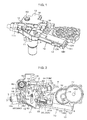
- Fig. 1 is a perspective view illustrating a multi-shaft drive device according to an exemplary embodiment.
- the multi-shaft drive device selectively drives plural movable mechanisms of an electric seat in a vehicle, not illustrated in the drawings, with a single motor 1.
- there are 3 movable mechanisms namely a lifter mechanism that adjusts a height of a seat face, a reclining mechanism that adjusts an angle of a seatback (backrest portion), and a slide mechanism that adjusts a front-rear position of the seat.
- These movable mechanisms are actuated by forward and reverse rotation of drive shafts provided to each mechanism.
- FIG. 1 A device case (case) 10 and a cover 13 that covers the device case 10 can be seen in Fig. 1.
- Fig. 2 is a plan view illustrating a removed state of the cover 13.
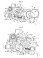
- Fig. 3 is a perspective view illustrating the inside of the device and the motor 1 with the device case 10 and the cover 13 removed, and
- Fig. 4 is a plan view corresponding to Fig. 3 .
- the device case 10 includes a clutch unit case portion 11 and a gearbox case portion 12 to be molded integrally.
- the clutch unit case portion 11 and the gearbox case portion 12 respectively house a clutch unit 2 and a gearbox 3.
- the motor 1 is fixed to a back face of the clutch unit case portion 11 with a motor shaft 1a to which a pinion 1b is fixed in a state projecting inside the device case 10.
- the clutch unit 2 includes: plural input portions 20 that transmit power of the motor 1, provided to each of the mechanisms described above; plural output portions 30 that are provided with output shafts 31 that connect to each of the mechanisms through power transmission member; clutch mechanisms 40 that are provided for each of the input portions 20 and the output portions 30, and that connect and disconnect the power transmission from the input portions 20 to each of the output shafts 31; a selector (switching portion) 50 that selectively places the clutch mechanisms 40 in a connected state; and an operation shaft 60 that actuates the selector 50.
- the plural input portions 20 are disposed to the periphery of the pinion 1b.
- the input portions 20 are formed in circular plate shapes, and each includes an input gear 21 configured by a flattened cog that enmeshes with the pinion 1b and an input side bevel gear 22 formed on one end face of the input gear 21.
- the input gear 21 and the bevel gear 22 are formed coaxially to each other on an input shaft 23.
- the input portions 20 are rotatably supported on the clutch unit case portion 11 through the input shafts 23 that run along a Z direction parallel to the motor shaft 1a. Note that configuration may be made such that the input gear 21 and the input side bevel gear 22 are indirectly supported on the device case 10 through another member rather than being directly supported on the device case 10.
- a plate shaped gear holder 15 is illustrated in Fig. 4 .
- the gear holder 15 is fixed inside the clutch unit case portion 11 of the device case 10 so as to cover each of the input portions 20.
- Two guide projections 16 projecting in the Z direction are formed at specific locations of the gear holder 15.
- Fig. 6 is a plan view illustrating a state in which the gear holder 15 has been removed.
- Fig. 7 illustrates the clutch unit 2.
- the selector 50 is a substantially rectangular plate shaped member that is long in the Y direction.
- the selector 50 is formed with two guide holes 54 corresponding to the guide projections 16 and extending in the Y direction.
- the respective guide projections 16 are inserted into the guide holes 54.
- the selector 50 is supported on the gear holder 15 so as to be capable of sliding in the Y direction guided by the guide projections 16.
- the side face on the right hand side in Fig. 7 is formed with a first cam face 51.
- a lower side of the side face on the left hand side is formed with a second cam face 52, and an upper side of the side face on the left hand side is formed with a rack 55 with a row of teeth running in the Y direction.
- the operation shaft 60 is rotatably supported inside the clutch unit case portion 11 with the rotation axis oriented in the Z direction.
- the operation shaft 60 is formed with a pinion 61 that enmeshes with the rack 55.
- An operation member such as a dial or a lever, not illustrated in the drawings, is fixed to the operation shaft 60 at the outside of the cover 13.
- the motor 1 is switched ON/OFF and rotation direction is selected by a switch, not illustrated in the drawings. All of the input portions 20 rotate when the motor 1 is actuated.
- the switch is preferably provided to the above operation member since this enables actuation of the clutch unit 2, namely selection of the movable mechanism, to be performed in a single operation together with the switching ON/OFF of the motor 1.
- the output portions 30 are disposed facing the respective cam faces 51, 52 on both X direction sides of the selector 50.
- two of the output portions 30 (a first output portion 30A and a second output portion 30B) are disposed separated from each other in the Y direction facing the first cam face 51, and one of the output portions 30 (a third output portion 30C) is disposed facing the second cam face S2.
- the output portions 30 include the output shafts 31, and each of the output portions 30 is respectively housed in a housing portion 14 provided inside the clutch unit case portion 11 in a state in which the output shaft 31 thrust directions are parallel to an X-Y plane that is orthogonal to the Z direction, and the output shafts 31 are inclined at a specific angle with respect to the cam faces 51, 52.
- each output portion 30 is configured by: the output shaft 31 positioned at a uniform distance from the selector 50; an output side bevel gear 35 on a leading end side (selector 50 side) of the output shaft 31 that is capable of rotating together as a unit with the output shaft 31, that is capable of projecting forwards or retreating along the output shaft 31 thrust direction with respect to the selector 50, and that is mounted coaxially to the output shaft 31; and a coil spring 39 that biases the output side bevel gear 35 to project forward in the direction of the selector 50.
- the output shafts 31 are formed with a circular cylinder portion 33 at a leading end side of a large diameter portion 32.
- a flange 32A is formed at a rear end of the large diameter portion 32.
- the large diameter portion 32 is supported rotatably and in a thrust direction immovable state inside a circular cylinder shaped shaft bearing holder portion 11c formed in the clutch unit case portion 11 through a shaft bearing bush 34 (see Fig. 4 ).
- Fig. 7 illustrates a semicircular cylinder shaped shaft bearing holder portion 11b formed at a clutch unit case portion 11 side.
- the output shaft 31 of the first output portion 30A is rotatably supported inside a worm support portion 120, described later, formed at the clutch unit case portion 11.
- the output side bevel gear 35 is configured by: a circular cylinder shaped slide shaft 36 that is externally mounted to an outer peripheral face of the circular cylinder portion 33 of the output shaft 31 such that relative rotation therebetween is not possible, namely such that the slide shaft 36 can rotate together as a unit with the circular cylinder portion 33, that is coaxially spline joined to the circular cylinder portion 33 so as to be capable of sliding in the thrust direction, and that is also capable of projecting forwards or retreating with respect to the selector 50 along the output shaft 31 thrust direction; a gear portion 37 that is integrally formed with a leading end side of the slide shaft 36 and that enmeshes with the input side bevel gear 22 of the input portion 20 when projecting forwards, and a pin 38 (contact portion) that projects out from the center of the gear portion 37.
- An outer peripheral side spline portion 33a and an inner peripheral side spline portion 36a that mutually engage with each other are respectively formed to the outer peripheral face of the circular cylinder portion 33 of the output shaft 31 and the inner peripheral face of the slide shaft 36 of the output side bevel gear 35.
- the outer peripheral side spline portion 33a of recessed and projected cross-section profile formed along the axial direction of the outer peripheral face of the circular cylinder portion 33, and the inner peripheral side spline portion 36a of recessed and projected cross-section profile formed along the axial direction of the inner peripheral face of the slide shaft 36 are slidably engaged with each other.
- the output side bevel gear 35 is accordingly mounted to the output shaft 31 such that the output side bevel gear 35 is rotatable together as a unit with the output shaft 31 and are slidable along the thrust direction.
- the output side bevel gear 35 and the input side bevel gear 22 configure the clutch mechanism 40 according to the present invention.
- the coil spring 39 is housed in a compressed state inside the circular cylinder portion 33 of the output shaft 31 and the slide shaft 36 of the output side bevel gear 35.
- the output side bevel gear 35 is biased in the selector 50 direction by the coil spring 39, and a leading end of the pin 38 abuts the cam faces 51, 52.
- the leading end face of the pin 38 is formed with a spherical face shape and makes sliding contact with the abutting cam faces 51, 52 when the selector 50 is moved in the Y direction.
- the first cam face 51 of the selector 50 is formed with recessed portions 53 (a first recessed portion 53A and a second recessed portion 53B) corresponding to the first output portion 30A and the second output portion 30B.
- the second cam face 52 is formed with a recessed portion 53 (a third recessed portion 53C) corresponding to the third output portion 30C.
- the third recessed portion 53 refers to an inclined face continuing to a Y direction end portion of the selector 50. Configuration is made such that when the selector 50 is moved in the Y direction, the pin 38 of any one of the output portions 30 fits into the corresponding recessed portion 53.
- the overall output side bevel gear 35 slides in the direction of the selector 50 due to the pin 38 fitting into the recessed portion 53. When this occurs, the output side bevel gear 35 engages and enmeshes with the input side bevel gear 22, achieving a connected state of the clutch mechanism 40.
- the pin 38 of the output side bevel gear 35 (a leading end portion of the output side bevel gear 35) penetrates a through hole 17a in a wall portion 17 formed to the gear holder 15.
- Shaft bearing bushes 18 shaft bearings
- the pins 38 are supported inside the shaft bearing bushes 18 so as to capable of sliding rotation and movable in the thrust direction.
- the output shafts 31 of each of the output portions 30 are connected to the drive shafts of each of the movable mechanisms described above through the power transmission members.
- flexible torque cables 5 (see Fig. 2 ) serving as the power transmission members are connected to the output shafts 31 of the second output portion 30B and the third output portion 30C.
- the torque cable 5 on the second output portion 30B side is connected to the drive shaft of the reclining mechanism mentioned above, and the torque cable 5 on the third output portion 30C side is connected to the drive shaft of the slide mechanism mentioned above.
- the torque cables 5 are inserted into mounting holes 32b (see Fig.
- a worm gear 70 and a gear 77 serving as the power transmission members are connected to the output shaft 31 of the first output portion 30A.
- the worm gear 70 and the gear 77 configure the gearbox 3 mentioned above.
- the worm gear 70 is configured including a worm 71 (power transmission members) formed coaxially and integrally to the rear end of the output shaft 31 (referred to below as the output shaft 31A) of the first output portion 30A, and a worm wheel 75 that enmeshes with the worm 71.
- the output shaft 31A and the worm 71 of the first output portion 30A are formed on a single circular column shaped transmission shaft 140.
- a flange 32a is formed at an intermediate portion of the transmission shaft 140.
- the worm 71 is inserted into and rotatably supported in the circular cylinder shaped worm support portion 120 formed to the gearbox case portion 12.
- a worm insertion hole 121 with a circular cylinder shaped inner peripheral face is formed inside the worm support portion 120.
- the worm insertion hole 121 is open at both ends.
- the circular cylinder shaped shaft bearing bush 34 (shaft bearing) is fitted into an opening portion 121a on one end side of the worm insertion hole 121 (the left hand side in Fig. 14 : the clutch unit 2 side) so as to be coaxial to the worm insertion hole 121.
- the shaft bearing bush 34 contacts a ring shaped stopper step portion 122 formed on the one end side opening portion 121 a, preventing the shaft bearing bush 34 from being pulled out of the opening portion 121a.
- the large diameter portion 32 of the output shaft 31A is supported inside the shaft bearing bush 34 so as to be capable of sliding rotation.
- a washer 141 is mounted interposed between the shaft bearing bush 34 and the flange 32a. The flange 32a engages with the stopper step portion 122 through the washer 141 and the shaft bearing bush 34, thereby restricting the overall transmission shaft 140 from moving towards the clutch unit 2 side.
- a circular column shaped small diameter portion 72 of uniform diameter is formed coaxially to the worm 71 at a worm 71 side end portion of the transmission shaft 140 with a step portion 73 interposed therebetween.
- the small radius portion 72 is rotatably supported by a shaft bearing portion 130 that is mounted to an opening portion (referred to below as the insertion side opening portion) 121b on the other end side of the worm support portion 120.
- the inner diameter of the worm insertion hole 121 is set with a dimension that forms a uniform gap with respect to the worm 71.
- the shaft bearing portion 130 is configured by a circular cylinder shaped cap 131 and a circular cylinder shaped shaft bearing bush 136 (shaft bearing) that is fixed to an inner peripheral portion at one end side of the cap 131.
- the one end side of the outer peripheral face of the cap 131 (outer peripheral face of the shaft bearing portion 130) is configured with a circular cylinder shaped face 132 that makes contact (face-to-face contact in the present example) with the inner peripheral face of the worm insertion hole 121.
- a male thread portion 133 of larger diameter than the circular cylinder face 132 is formed coaxially to the circular cylinder face 132.
- a circular cylinder face 132 side end face of the cap 131 is formed with a shaft bearing hole 134 that is coaxial to the circular cylinder face 132.
- the shaft bearing bush 136 is pushed into and fixed to the shaft bearing hole 134.
- the shaft bearing bush 136 is in a completely pushed in state inside the shaft bearing hole 134.
- a male thread portion 133 side end face of the cap 131 is formed with a hexagonal hole 135.
- An end portion at an insertion side opening portion 121b side of the worm insertion hole 121 is formed with a female thread portion 123 into which the male thread portion 133 is screwed.
- the shaft bearing bush 34, the circular cylinder face 132 and the male thread portion 133 that configure the outer peripheral face of the cap 131, the shaft bearing hole 134 of the cap 131, and the shaft bearing bush 136 are all coaxial to the worm insertion hole 121.
- the shaft bearing portion 130 is mounted to the insertion side opening portion 121b of the worm support portion 120 by sliding the circular cylinder face 132 of the cap 131 into the insertion side opening portion 121b of the worm support portion 120 and screwing the male thread portion 133 into the female thread portion 123.
- the small radius portion 72 of the worm 71 is inserted into and supported inside the shaft bearing bush 136 so as to be capable of sliding rotation.
- a washer 74 is inserted over the small radius portion 72, and the step portion 73 of the worm 71 engages with the cap 131 through the washer 74, thereby restricting the overall transmission shaft 140 from moving towards the direction opposite to the clutch unit 2.
- An intermediate portion of the worm support portion 120 is formed with a notch 124 that exposes a portion of the worm 71 so as to be capable of engaging with the worm wheel 75.
- the transmission shaft 140 is set in the worm support portion 120 in the following manner. Firstly, the shaft bearing bush 34 and the washer 141 are mounted to the large diameter portion 32 of the output shaft 31A, and the coil spring 39 is loaded inside the circular cylinder portion 33 of the output shaft 31A. Then the transmission shaft 140 is inserted into the worm insertion hole 121 from the output shaft 31 side. The pin 38 is then inserted into the shaft bearing bush 18 that is fixed to the through hole 17a of the wall portion 17 of the gear holder 15, and the outer peripheral side spline portion 33a of the output shaft 31A is fitted into the inner peripheral side spline portion 36a of the output side bevel gear 35 that is housed in the housing portion 14.
- the circular cylinder face 132 of the cap 131 is inserted into the insertion side opening portion 121b, and the small radius portion 72 is inserted into the shaft bearing bush 136 whilst screwing the male thread portion 133 into the female thread portion 123.
- the transmission shaft 140 that is rotatably supported by the worm support portion 120, and the output side bevel gear 35 that is mounted on the output shaft 31A of the transmission shaft 140, are thereby coupled together, configuring a compound gear 145 in which the output side bevel gear 35 is on a leading end side, the worm 71 is on a rear end side, and the output side bevel gear 35 is spline joined to the worm 71.
- the small radius portion 72 at the rear end portion of the worm 71 is supported by the shaft bearing bush 136 of the shaft bearing portion 130, and the large diameter portion 32 of the output shaft 31A at the intermediate portion is supported by the shaft bearing bush 34 disposed in the one end side opening portion 121a of the worm support portion 120, such that the transmission shaft 140 is rotatable whilst being positioned in a radial direction.
- the amount by which the cap 131 is screwed into the female thread portion 123 can be adjusted by rotating the cap 131, enabling adjustment of the thrust direction position of the worm 71.
- the leading end pin 38 is supported by the shaft bearing bush 18 of the wall portion 17 of the gear holder 15, and a rear end portion of the slide shaft 36 is rotatably supported through a shaft bearing bush 150 (shaft bearing) illustrated in Fig. 11 .
- the shaft bearing bush 150 is retained interposed between a semicircular cylinder shaped shaft holder portion 11d formed at the clutch unit case portion 11 of the device case 10 and a shaft holder portion 13d formed at the cover 13, as illustrated in Fig. 16 .
- the leading end pin 38 and the rear end portion of the slide shaft 36 are accordingly respectively supported by the shaft bearing bush 18 and the shaft bearing bush 150 so as to be capable of sliding rotation.
- the output side bevel gear 35 R can accordingly be positioned with respect to the radial direction thereof in a state of being supported at both ends thereof.
- the leading end pin 38 of the output side bevel gear 35, the rear end portion of the worm 71, the large diameter portion 32 at the rear end portion of the output shaft 31A, and the slide shaft 36 of the output side bevel gear 35 are each respectively supported in a state capable of sliding rotation by the shaft bearing bush 18, the shaft bearing bush 136, the shaft bearing bush 34, and the shaft bearing bush 150.
- the clearance between the outer peripheral side spline portion 33a of the output shaft 31A and the inner peripheral side spline portion 36a of the slide shaft 36 of the output side bevel gear 35 is set such that shaft misalignment between the transmission shaft 140 and the output side bevel gear 35 can be absorbed.
- the clearance between the respective spline portions 33a, 36a is set comparatively loosely such that the outer peripheral side spline portion 33a of the output shaft 31A can be fitted into the inner peripheral side spline portion 36a of the output side bevel gear 35 even when the output side bevel gear 35 that is supported by the shaft bearing bushes 18, 150 is not strictly coaxial to the transmission shaft 140 supported by the shaft bearing bushes 34, 136 due to low mutual coaxiality between the shaft bearing bushes 18, 150, 34, 136.
- the clearance between the respective spline portions 33a, 36a is set relatively loosely such that the slide shaft 36 is able to move within a preset range in the radial direction with respect to the output shaft 31A.
- the gearbox 3 is configured by the worm gear 70 that includes the worm 71 and the worm wheel 75 that engages with the worm 71, and the gear 77.
- the worm wheel 75 is rotatably supported by the gearbox case portion 12.
- a small diameter gear 76 is formed at the center of the worm wheel 75.
- the small diameter gear 76 engages with the gear 77.
- the gear 77 is fixed to a drive shaft 160 of the lifter mechanism mentioned above that is orthogonal to the transmission shaft 140.
- the multi-shaft drive device of the first exemplary embodiment described above is fixed to a member such as a seat frame using plural screw insertion holes 19 provided to peripheral edges of the device case 10 and the cover 13.
- Fig. 7 illustrates a state in which the pin 38 of the output side bevel gear 35 of the first output portion 30A has been fitted into the first recessed portion 53A by rotating the operation shaft 60 to move the selector 50 in the Y direction.
- the output side bevel gear 35 of the first output portion 30A engages with the input side bevel gear 22 corresponding to the first output portion 30A, resulting in a connected state of the clutch mechanism 40.
- the pins 38 are pressed by the cam faces 51, 52 and the output side bevel gears 35 are separated from the corresponding input side bevel gears 22, such that the respective clutch mechanisms 40 are in a disconnected state.
- the pin 38 of the third output portion 30C projects forward into the third recessed portion 53C, and the output side bevel gear 35 of the third output portion 30C enmeshes with the corresponding input side bevel gear 22, resulting in a clutch mechanism 40 connected state.
- the pins 38 are pressed by the cam face 51, and the output side bevel gears 35 separate from the corresponding input side bevel gears 22, such that the respective clutch mechanisms 40 are in a disconnected state.
- the selector 50 is moved back and forth in the Y direction by forward and reverse rotation of the operation shaft 60. Along the path of this movement, the pins 38 project forwards into any one of the recessed portions 53A to 53C of the selector 50, such that when this occurs, one of the output portions 30 out of the first to third output portions 30A to 30C is selected as described above.
- the output side bevel gear 35 of the selected output portion 30 enmeshes with the corresponding input side bevel gear 22 to achieve the clutch mechanism 40 connected state.
- the power transmission members for transmitting rotation of the output shaft 31 to the movable mechanisms are the conventional torque cables 5.
- the worm 71 is directly connected to the output shaft 31A, with the power transmission members configured by the gearbox 3 including the worm 71, the worm gear 70 and the gear 77.
- the torque cable 5 and a member to support the torque cable 5 are not required, with a connection structure between the output shaft 31 and the drive shaft 160 of the movable mechanism being simpler than previously. Accordingly, the advantageous effects are exhibited whereby assembly is made easier, increasing productivity, and it is possible to reduce the number of components, thereby enabling a reduction in costs. Moreover, in the first output portion 30A, the effort of attaching a torque cable 5 can be avoided, this also enabling productivity to be increased.
- the worm 71 provided to the gearbox 3 is integrally formed with the output shaft 31A. A further improvement in productivity is accordingly possible since the number of component assembly steps and the number of components can be reduced.
- the device case 10 is integrally provided with the gearbox case portion 12 for housing the gearbox 3 that includes the worm 71, and the clutch unit case portion 11 for housing the clutch unit 2.
- the device case can therefore be configured as a single component. Assembly is accordingly made even easier and productivity is further increased, and a further reduction in the number of components is possible, enabling an even further reduction in costs to be achieved.
- the gearbox case portion 12 and the clutch unit case portion 11 are configured by separate bodies, the number of screw insertion holes in the gearbox case portion 12 that configure a fixing portion to a member such as a seat frame is relatively small, however by forming the gearbox case portion 12 integrally with the clutch unit case portion 11, the number of the screw insertion holes 19 increases, with the advantage of increasing rigidity in a fixed state.
- the shaft bearing bush 34 that supports the rear end portion of the output shaft 31A also functions as a shaft bearing supporting the worm 71, thereby acting as a common shaft bearing. Productivity is accordingly further increased, and a reduction in costs is made possible.
- the small radius portion 72 of the worm 71 is inserted into the shaft bearing bush 136 of the shaft bearing portion 130 that is mounted coaxially to the worm insertion hole 121 so as to be capable of sliding rotation.
- the output shaft 31A is thereby supported by the shaft bearing bush 34, and positioning in a radial direction of the worm 71 is performed with high precision.
- the step portion 73 of the worm 71 engages with the cap 131 of the shaft bearing portion 130, such that positioning in a thrust direction of the worm 71 is performed with high precision.
- the worm 71 can be adjusted in the thrust direction by adjusting the amount by which the cap 131 is rotated and screwed into the female thread portion 123.
- the shaft bearing portion 130 is configured simply by fixing the shaft bearing bush 136 to the cap 131, and the shaft bearing portion 130 is easily mounted to the worm insertion hole 121 by screwing the cap 131 into the worm insertion hole 121.
- the worm 71 is accordingly supported inside the worm insertion hole 121 by simply inserting the small radius portion 72 at the end portion of the worm 71 into the shaft bearing bush 136 of the shaft bearing portion 130. High precision positioning for the worm 71 in both the thrust direction and the radial direction is accordingly achieved with a simple structure.
- the transmission shaft 140 is rotatably supported by the gearbox case portion 12 through the shaft bearing bushes 34, 136 at two positions separated from each other in the axial direction.
- the pin 38 (leading end portion) and the slide shaft 36 of the output side bevel gear 35 are supported by the gearbox case portion 12 through the shaft bearing bushes 18, 150 so as to be rotatable and capable of moving in the thrust direction.
- the clearance between the outer peripheral side spline portion 33a and the inner peripheral side spline portion 36a is set relatively loosely, such that the slide shaft 36, namely the output side bevel gear 35, is capable of moving in the radial direction within a preset range with respect to the output shaft 31A.
- the clearance between the outer peripheral side spline portion 33a of the output shaft 31A and the inner peripheral side spline portion 36a of the slide shaft 36 of the output side bevel gear 35 is set relatively loosely so as to be able to absorb shaft misalignment between the transmission shaft 140 and the output side bevel gear 35.
- the output shaft 31A of the transmission shaft 140 can accordingly be spline joined to the output side bevel gear 35 even when there is a low degree of mutual coaxiality between the shaft bearing bushes 18, 150 of the output side bevel gear 35 and the shaft bearing bushes 34, 136 of the transmission shaft 140.
- the coaxiality between the shaft bearing bushes 18, 150, 34, 136 therefore does not need to be maintained with high precision, making manufacture easier and increasing the productivity in mass production as a result.
- the gearbox 3 is configured including the worm 71, enabling a large speed reduction ratio to be obtained in a single step by the worm 71. A reduction in the size of the device can accordingly be achieved.
- the plural clutch mechanisms 40 provided for each of the plural output portions 30 can selectively be placed in the connected state by the selector 50, enabling the selected output portion 30 to transmit power from the input portion 20 to the output shaft 31. Due to providing the clutch mechanisms 40 for each of the plural output portions 30, a smaller configuration can be achieved for each of the clutch mechanisms 40, enabling a reduction in the size of the device.
- the output side bevel gears 35 that are mounted so as to be capable of rotating as a unit together with the output shafts 31A and also be capable of sliding in the thrust direction with respect to the output shafts 31A, mutually enmesh with the input side bevel gears 22 provided to the input portions 20 to achieve the clutch mechanism 40 connected state.
- the clutch mechanism 40 achieves the disconnected state when the output side bevel gear 35 separates from the input side bevel gear 22. Namely the clutch mechanisms 40 can be connected and disconnected by making the output side bevel gears 35 project forwards or retreat with respect to the input side bevel gears 22, enabling a simple configuration for the clutch mechanisms 40.
- the clutch mechanism is configured by plural clutch mechanisms 40 provided to each of the plural output portions 30 and the selector 50, however the present invention is not limited thereto, and appropriate modifications may be made to the configuration of the clutch mechanism.
- configuration may be made wherein a rotating body (such as a gear) supported so as to be capable of movement with respect to the device case is selectively interposed between plural output portions and plural input portions and the output portions and the input portions are connected to each other by the rotating body.
- configuration is made wherein the outer peripheral side spline portion 33a of the output shaft 31A and the inner peripheral side spline portion 36a of the slide shaft 36 of the output side bevel gear 35 (gear) are engaged so as to be capable of sliding movement against each other, however appropriate modifications may be made to the engagement structure between the output shaft and the slide shaft of the gear.
- configuration may be made wherein one out of an output shaft and a slide shaft is formed with a polygonal cross-section profile, and an inner peripheral face of the other out of the output shaft and the slide shaft is formed with a polygonal cross-section profile that engages with the polygonal outer peripheral face of the other so as to be capable of sliding movement along the axial direction.
- configuration is made wherein the clearance between the outer peripheral side spline portion 33a (outside engagement portion) and the inner peripheral side spline portion 36a (inside engagement portion) is set relatively loosely to allow radial direction movement of the slide shaft 36 with respect to the output shaft 31A within a preset range, however the present invention is not limited thereto.
- Configuration may be made wherein the clearance between the outside engagement member and the inside engagement member is set so as to be tight.
- the output portion 30 is provided with the output shaft 31 and the output side bevel gear 35, however the present invention is not limited thereto, and appropriate modifications may be made to the configuration of the output portion.
- the transmission shaft 140 is supported on the gearbox case portion 12 through the shaft bearing bushes 34, 136 at two positions separated in the axial direction, and the pin 38 and the slide shaft 36 of the output side bevel gear 35 (gear) are supported on the gearbox case portion 12 through the shaft bearing bushes 18, 150, however the present invention is not limited thereto, and appropriate modifications may be made to the support structure of the transmission shaft and the gear on the gearbox case.
- shaft bearing portion 130 is configured by the cap 131 and the shaft bearing bush 136
- the present invention is not limited thereto, and appropriate modifications may be made to the configuration of the shaft bearing portion.
- configuration may be made wherein the shaft bearing bush 136 of the above exemplary embodiment is omitted, and the small radius portion 72 of the worm 71 is directly inserted inside the cap 131.
- configuration is made wherein the shaft bearing portion 130 engages with the step portion 73 of the worm 71 in a state in which the circular cylinder shaped face 132 formed to the outer peripheral face of the cap 131 of the shaft bearing portion 130 contacts the inner peripheral face of the worm insertion hole 121, the male thread portion 133 formed to the outer peripheral face of the cap 131 is screwed into the female thread portion 123 formed to the inner peripheral face of the worm insertion hole 121, and the small radius portion 72 of the worm 71 is coaxially inserted into the shaft bearing bush 136 so as to be capable of sliding rotation therewith.
- the present invention is however not limited thereto, and appropriate modifications may be made to the support structure of the worm 71.
- the gearbox 3 includes the worm 71 and the worm wheel 75, however the present invention is not limited thereto, and appropriate modifications may be made to the configuration of the gearbox.
- the gearbox may only be provided with plural flattened cogs.
- the power transmission member includes flattened cogs in such a configuration.
- the device case 10 is integrally provided with the clutch unit case portion 11 and the gearbox case portion 12, however the present invention is not limited thereto. Configuration may be made wherein the clutch unit case portion and the gearbox case portion are formed as separate bodies and integrally coupled together using fasteners or the like.
- the output shaft 31 and the worm 71 are formed integrally to each other, however the present invention is not limited thereto configuration may be made wherein the output shaft and the worm are formed as separate bodies and coaxially and integrally coupled or joined together.
- configuration is made including the plural input portions 20, however the present invention is not limited thereto, and configuration may be made to switch a connected state between a single input portion and plural output portions.
- the multi-shaft drive device is applied so as to selectively drive plural movable mechanisms in an electric seat in a vehicle, however there is no limitation thereto and the multi-shaft drive device of the present invention may be applied to various machines to which plural movable mechanisms are provided.
Landscapes
- Engineering & Computer Science (AREA)
- General Engineering & Computer Science (AREA)
- Mechanical Engineering (AREA)
- Aviation & Aerospace Engineering (AREA)
- Transportation (AREA)
- Gear Transmission (AREA)
- Seats For Vehicles (AREA)
- Mechanical Operated Clutches (AREA)
- Transmission Devices (AREA)
Abstract
Description
- The present invention relates to a multi-shaft drive device that is preferably provided for example to a vehicle seat and that selectively drives plural movable mechanisms with a single motor.
- Many vehicle seats are of a type enabling position adjustment of plural portions so as to suit the build and posture of an occupant, the position adjustment includes, for example, sliding the overall seat in the front-rear direction, moving the height of the seat face up and down, or reclining the seatback (backrest). Such adjustment of the plural movable portions may be performed manually, however more convenient electric seats are provided that use the drive of a motor to perform adjustments.
- In order to independently drive respective movable portions, a configuration wherein motors are individually coupled to respective drive shafts that are each coupled to a movable portion may be considered, however this would increase the number of motors. Since it is more efficient for a single motor to drive plural output shafts, proposals have been made wherein the power of a motor is transmitted through clutches to respective output shafts coupled to the plural movable portions, and each of the movable portions is selectively driven by connecting and disconnecting the clutches (see for example Japanese National-Phase Publication No.
H3-501832 - Patent Document 1: Japanese National-Phase Publication No.
H3-501832 - In the above configuration wherein rotation of the output shafts is transmitted to the movable locations using flexible cables, there is room for improvement in terms of increasing productivity because the structure includes large number of peripheral components, and the effort is involved in attaching the cables.
- In consideration of the above circumstances, a subject of the present invention is to provide a multi-shaft drive device capable of increasing productivity compared to previously. Solution Addressing Subject
- A multi-shaft drive device of a first aspect includes: an input portion to which power of a motor is transmitted; plural output portions, each of which is provided with an output shaft, the output shafts being individually connected to plural movable mechanisms; a clutch part capable of selectively disconnecting power transmission from the input portion to the plural output portions; and a gearbox that includes a power transmission member provided coaxially to the output shaft of at least one output portion out of the plural output portions, and that connects together the output shaft and the movable mechanism.
- In the first aspect, the output shaft of at least one output portion out of the plural output portions is connected to the movable mechanism by the gearbox that includes the transmission member provided coaxially to the output shaft. The connection structure between the output shaft and a drive shaft of the movable mechanism can accordingly be made simpler than when employing a conventional cable for power transmission. Productivity can accordingly be increased due to assembly being made easier.
- A multi-shaft drive device of a second aspect is the first aspect, wherein the power transmission member is integrally formed with the output shaft.
- In the second aspect, the power transmission member provided to the gearbox is integrally formed with the output shaft provided at the output portion. Productivity can accordingly be further increased since the number of components and the number of component assembly processes can be reduced.
- A multi-shaft drive device of a third aspect is either the first aspect or the second aspect, wherein the power transmission member includes a worm, and the gearbox includes a worm wheel that engages with the worm.
- In the third aspect, the gearbox is configured including the worm and the worm wheel, namely including a worm gear, thereby enabling a large speed reduction ratio to be obtained in a single step by the worm gear. A reduction in the size of the device can accordingly be achieved.
- A multi-shaft drive device of a fourth aspect is any one of the first aspect to the third aspect, further including: a device case integrally provided with: a clutch unit case portion housing the plural output portions, the input portion, and a clutch unit, the clutch unit including the clutch part; and a gearbox case portion housing the gearbox.
- In the fourth aspect, it is possible to configure the device case as a single component because the device case is integrally providing with the gearbox case portion and the clutch unit case portion, the gearbox case portion housing the gearbox including the power transmission member and the clutch unit case portion housing the clutch unit. Productivity can accordingly be further increased since assembly can be made easy.
- A multi-shaft drive device of a fifth aspect is any one of the first aspect to the fourth aspect, wherein the clutch part includes: plural clutch mechanisms that are respectively provided to each of the plural output portions, and that disconnect power transmission from the input portion to the output shafts; and a switching part for selectively placing the plural clutch mechanisms in a connected state.
- In the fifth aspect, the plural clutch mechanisms respectively provided to each of the plural output portions can be selectively placed in the connected state by the switching part, thereby enabling power transmission from the input portion to the output shaft of the selected output portion. A reduction in size of the configuration of each clutch mechanism is accordingly enabled due to respectively providing the clutch mechanisms to each of the plural output portions, thereby enabling a reduction in the size of the device.
- A multi-shaft drive device of a sixth aspect is the third aspect, wherein: an end portion of the worm is formed with a projection portion that is coaxial to the worm with a step portion interposed therebetween; the worm is coaxially inserted into a worm insertion hole that is formed in the gearbox case portion and that has a circular cylinder shaped inner peripheral face, and the worm is supported by a shaft bearing portion mounted in the worm insertion hole; a circular cylinder shaped face formed at an outer peripheral face of the shaft bearing portion makes contact with the inner peripheral face of the worm insertion hole, and a male thread portion formed at the outer peripheral face is screwed together with a female thread portion formed at the inner peripheral face, and the shaft bearing portion engages with the step portion in a state in which the projection portion is coaxially inserted inside the shaft bearing portion so as to be capable of sliding rotation.
- In the sixth aspect, the circular cylinder face formed at the outer peripheral face of the shaft bearing portion makes contact with the circular cylinder shaped inner peripheral face of the worm insertion hole of the gearbox case portion, thereby positioning the shaft bearing portion coaxially to the worm insertion hole. The projection portion of the worm is inserted inside the shaft bearing portion so as to be coaxial to and capable of sliding rotation, whereby the worm is positioned with a high degree of precision in the worm radial direction. The step portion at the end portion of the worm engages with the shaft bearing portion, thereby positioning the worm with a high degree of precision in a worm thrust direction. A position in the thrust direction of the worm can be changed by adjusting an amount by which the cap is screwed into the worm insertion hole, enabling thrust direction adjustment of the worm to be performed. The worm can accordingly be positioned with a high degree of precision in both the thrust direction and the radial direction by employing a simple configuration.
- A multi-shaft drive device of a seventh aspect is either the third aspect or the sixth aspect, wherein: a transmission shaft is configured with the output shaft formed at one end side of the transmission shaft and the worm formed at the other end side of the transmission shaft; the output portion is further provided with a gear having a slide shaft, the gear is formed with a gear portion at a leading end portion of the slide shaft; the slide shaft of the gear is mounted to the output shaft so as to be rotatable together as a unit with the output shaft and so as to be capable of sliding in a thrust direction with respect to the output shaft; and at least two positions that are separated in the axial direction of the transmission shaft are rotatably supported through shaft bearings by the gearbox case portion, and a leading end portion and the slide shaft of the gear are rotatably supported by the gearbox case portion through shaft bearings so as to be movable along the thrust direction.
- In the seventh aspect, the slide shaft of the gear provided to the output portion is mounted to the output shaft provided to the transmission shaft so as to be rotatable together as a unit with the output shaft and so as to be capable of sliding in the thrust direction with respect to the output shaft. The transmission shaft is rotatably supported by the gearbox case portion through the shaft bearings at least at two positions separated in the axial direction of the transmission shaft, and the leading end portion and the slide shaft of the gear are rotatably supported by the gearbox case portion through the shaft bearings so as to be movable along the thrust direction. Since the leading end portion and slide shaft of the gear that slides with respect to the output shaft (transmission shaft) are supported by the gearbox case portion through the shaft bearings, the gear can be supported with sufficient support force. As a result, support of the gear can be stabilized, thereby enabling noise generation and damage to be prevented.
- A multi-shaft drive device of an eighth aspect is the seventh aspect, wherein: an outside engagement portion formed at one, and an inside engagement portion formed at the other, of the output shaft and the slide shaft, slidably engage to each other such that the gear is mounted to the output shaft so as to be rotatable together as a unit with the output shaft and also capable of sliding in the thrust direction with respect to the output shaft, the outside engagement portion has a recessed and projected cross-section profile formed at an outer peripheral face along an axial direction of the one, and the inside engagement portion has a recessed and projected cross-section profile formed at an inner peripheral face along the axial direction of the other; and a clearance between the outside engagement portion and the inside engagement portion is set such that the slide shaft is movable in the radial direction thereof with respect to the output shaft within a preset range.
- In the eighth aspect, the outside engagement portion of the output shaft and the inside engagement portion of the slide shaft of the gear engage with each other such that the gear is mounted to the output shaft so as to be capable of rotating together as a unit with the output shaft and also capable of sliding in the thrust direction with respect to the output shaft. In the present aspect, the clearance between the outside engagement portion and the inside engagement portion is set such that the slide shaft, namely the gear, is movable in the radial direction thereof with respect to the output shaft within a preset range. Accordingly, the gear and the transmission shaft can be supported on the plural shaft bearings and can engage with each other so as to be both rotatable together as a unit and slidable with respect to each other in the thrust direction even when there is a low degree of coaxiality between the gear side shaft bearings and the transmission shaft side shaft bearings. Since requirements of coaxiality for the plural shaft bearings can be reduced, manufacture can be made easier, and mass productivity can be increased.
- A multi-shaft drive device of a ninth aspect is either the fifth aspect or the sixth aspect, wherein the gear is an output side bevel gear that enmeshes with an input side bevel gear provided to the input portion when the clutch part is connected.
- In the ninth aspect, the output side bevel gear is mounted to the output shaft so as to be rotatable together as a unit with the output shaft and so as also be capable of sliding in the thrust direction with respect to the output shaft. The output side bevel gear enmeshes with the input side bevel gear provided to the input portion to place the clutch part in a connected state. The output side bevel gear moreover separates from the input side bevel gear to place the clutch part in a disconnected state. Namely, the clutch part can be connected or disconnected by projecting forward or retreating the output side bevel gear with respect to the input side bevel gear, thereby enabling the clutch art to be achieved with a simple configuration.
- A multi-shaft drive device of a tenth aspect is any one of the first aspect to the ninth aspect, wherein the movable mechanisms actuate movable locations of a vehicle seat.
- In the tenth aspect, a single motor can be used to selectively drive plural movable mechanisms provided to a vehicle seat, including for example a lifter mechanism that adjusts a height of a seat face, a reclining mechanism that adjusts an angle of a seatback (backrest portion), and a slide mechanism that adjusts a front-rear position of the seat.
- According to the present invention, the advantageous effect is exhibited of providing a multi-shaft drive device capable of increasing productivity compared to previously.
-
-
Fig. 1 is an overall perspective view illustrating a multi-shaft drive device according to a first exemplary embodiment of the present invention. -
Fig. 2 is an overall plan view illustrating the multi-shaft drive device in a state with a cover removed. -
Fig. 3 is a perspective view illustrating the multi-shaft drive device in a state with a device case and the cover removed. -
Fig. 4 is a plan view ofFig. 3 . -
Fig. 5A is a plan view, andFig. 5B is a side view, respectively illustrating a state in which a gear holder illustrated inFig. 4 has been removed. -
Fig. 6 is a drawing illustrating a state in which the gear holder illustrated inFig. 2 has been removed. -
Fig. 7 is a plan view illustrating a clutch unit of the multi-shaft drive device. -
Fig. 8A is a perspective view, andFig. 8B is a cross-section, respectively illustrating an output portion of the multi-shaft drive device. -
Fig. 9 is a partial cross-section plan view illustrating a support structure for a pin of an output side bevel gear of the multi-shaft drive device. -
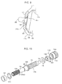
Fig. 10 is an exploded view illustrating members including a transmission shaft with a worm directly integrally formed with an output shaft, and a shaft bearing portion. -
Fig. 11 is a side view illustrating a mounted state of an output side bevel gear to the transmission shaft. -
Fig. 12 is an overall plan view illustrating the multi-shaft drive device. -
Fig. 13 is a cross-section taken along F-F inFig. 12 . -
Fig. 14 is a cross-section taken along G-G inFig. 6 . -
Fig. 15 is a cross-section illustrating a supported state of an end portion of a worm at a shaft bearing portion. -
Fig. 16 is a cross-section illustrating a support structure of an output side bevel gear of a first output portion. - Explanation follows regarding an exemplary embodiment of the present invention with reference to drawings.
-
Fig. 1 is a perspective view illustrating a multi-shaft drive device according to an exemplary embodiment. The multi-shaft drive device selectively drives plural movable mechanisms of an electric seat in a vehicle, not illustrated in the drawings, with asingle motor 1. In the present example, there are 3 movable mechanisms, namely a lifter mechanism that adjusts a height of a seat face, a reclining mechanism that adjusts an angle of a seatback (backrest portion), and a slide mechanism that adjusts a front-rear position of the seat. These movable mechanisms are actuated by forward and reverse rotation of drive shafts provided to each mechanism. - A device case (case) 10 and a
cover 13 that covers thedevice case 10 can be seen inFig. 1. Fig. 2 is a plan view illustrating a removed state of thecover 13.Fig. 3 is a perspective view illustrating the inside of the device and themotor 1 with thedevice case 10 and thecover 13 removed, andFig. 4 is a plan view corresponding toFig. 3 . - As illustrated in
Fig. 2 , thedevice case 10 includes a clutchunit case portion 11 and agearbox case portion 12 to be molded integrally. The clutchunit case portion 11 and thegearbox case portion 12 respectively house aclutch unit 2 and agearbox 3. Themotor 1 is fixed to a back face of the clutchunit case portion 11 with amotor shaft 1a to which apinion 1b is fixed in a state projecting inside thedevice case 10. - As illustrated in
Figs. 5 , theclutch unit 2 includes:plural input portions 20 that transmit power of themotor 1, provided to each of the mechanisms described above;plural output portions 30 that are provided withoutput shafts 31 that connect to each of the mechanisms through power transmission member;clutch mechanisms 40 that are provided for each of theinput portions 20 and theoutput portions 30, and that connect and disconnect the power transmission from theinput portions 20 to each of theoutput shafts 31; a selector (switching portion) 50 that selectively places theclutch mechanisms 40 in a connected state; and anoperation shaft 60 that actuates theselector 50. - The
plural input portions 20 are disposed to the periphery of thepinion 1b. Theinput portions 20 are formed in circular plate shapes, and each includes aninput gear 21 configured by a flattened cog that enmeshes with thepinion 1b and an inputside bevel gear 22 formed on one end face of theinput gear 21. Theinput gear 21 and thebevel gear 22 are formed coaxially to each other on aninput shaft 23. Theinput portions 20 are rotatably supported on the clutchunit case portion 11 through theinput shafts 23 that run along a Z direction parallel to themotor shaft 1a. Note that configuration may be made such that theinput gear 21 and the inputside bevel gear 22 are indirectly supported on thedevice case 10 through another member rather than being directly supported on thedevice case 10. - A plate shaped
gear holder 15 is illustrated inFig. 4 . As illustrated inFig. 3 , thegear holder 15 is fixed inside the clutchunit case portion 11 of thedevice case 10 so as to cover each of theinput portions 20. Twoguide projections 16 projecting in the Z direction are formed at specific locations of thegear holder 15.Fig. 6 is a plan view illustrating a state in which thegear holder 15 has been removed. -
Fig. 7 illustrates theclutch unit 2. As illustrated inFig. 7 , theselector 50 is a substantially rectangular plate shaped member that is long in the Y direction. Theselector 50 is formed with twoguide holes 54 corresponding to theguide projections 16 and extending in the Y direction. Therespective guide projections 16 are inserted into the guide holes 54. Theselector 50 is supported on thegear holder 15 so as to be capable of sliding in the Y direction guided by theguide projections 16. - Out of the two side faces of the
selector 50 running in the Y direction, the side face on the right hand side inFig. 7 is formed with afirst cam face 51. A lower side of the side face on the left hand side is formed with asecond cam face 52, and an upper side of the side face on the left hand side is formed with arack 55 with a row of teeth running in the Y direction. Theoperation shaft 60 is rotatably supported inside the clutchunit case portion 11 with the rotation axis oriented in the Z direction. Theoperation shaft 60 is formed with apinion 61 that enmeshes with therack 55. An operation member such as a dial or a lever, not illustrated in the drawings, is fixed to theoperation shaft 60 at the outside of thecover 13. When theoperation shaft 60 is rotated through the operation member, theselector 50 is moved by the rotatingpinion 61 back and forth along the Y direction through therack 55, according to the rotation direction of theoperation shaft 60. - The
motor 1 is switched ON/OFF and rotation direction is selected by a switch, not illustrated in the drawings. All of theinput portions 20 rotate when themotor 1 is actuated. The switch is preferably provided to the above operation member since this enables actuation of theclutch unit 2, namely selection of the movable mechanism, to be performed in a single operation together with the switching ON/OFF of themotor 1. - As illustrated in
Fig. 7 , theoutput portions 30 are disposed facing the respective cam faces 51, 52 on both X direction sides of theselector 50. In the present example, two of the output portions 30 (afirst output portion 30A and asecond output portion 30B) are disposed separated from each other in the Y direction facing thefirst cam face 51, and one of the output portions 30 (athird output portion 30C) is disposed facing the second cam face S2. Theoutput portions 30 include theoutput shafts 31, and each of theoutput portions 30 is respectively housed in ahousing portion 14 provided inside the clutchunit case portion 11 in a state in which theoutput shaft 31 thrust directions are parallel to an X-Y plane that is orthogonal to the Z direction, and theoutput shafts 31 are inclined at a specific angle with respect to the cam faces 51, 52. - As illustrated in
Figs. 8 , eachoutput portion 30 is configured by: theoutput shaft 31 positioned at a uniform distance from theselector 50; an outputside bevel gear 35 on a leading end side (selector 50 side) of theoutput shaft 31 that is capable of rotating together as a unit with theoutput shaft 31, that is capable of projecting forwards or retreating along theoutput shaft 31 thrust direction with respect to theselector 50, and that is mounted coaxially to theoutput shaft 31; and acoil spring 39 that biases the outputside bevel gear 35 to project forward in the direction of theselector 50. - The
output shafts 31 are formed with acircular cylinder portion 33 at a leading end side of alarge diameter portion 32. A flange 32A is formed at a rear end of thelarge diameter portion 32. As illustrated inFig. 7 , in theoutput shaft 31 of thethird output portion 30C, thelarge diameter portion 32 is supported rotatably and in a thrust direction immovable state inside a circular cylinder shaped shaftbearing holder portion 11c formed in the clutchunit case portion 11 through a shaft bearing bush 34 (seeFig. 4 ). In theoutput shaft 31 of thesecond output portion 30B, thelarge diameter portion 32 is supported through theshaft bearing bush 34 in a rotatable and thrust direction immovable state due to being interposed between semicircular cylinder shaped shaft bearing holder portions respectively formed to the clutchunit case portion 11 and thecover 13 that configure a circular cylinder shape in a mounted state of thecover 13 to thedevice case 10.Fig. 7 illustrates a semicircular cylinder shaped shaftbearing holder portion 11b formed at a clutchunit case portion 11 side. Theoutput shaft 31 of thefirst output portion 30A is rotatably supported inside aworm support portion 120, described later, formed at the clutchunit case portion 11. - As illustrated in
Figs. 8A and 8B , the outputside bevel gear 35 is configured by: a circular cylinder shapedslide shaft 36 that is externally mounted to an outer peripheral face of thecircular cylinder portion 33 of theoutput shaft 31 such that relative rotation therebetween is not possible, namely such that theslide shaft 36 can rotate together as a unit with thecircular cylinder portion 33, that is coaxially spline joined to thecircular cylinder portion 33 so as to be capable of sliding in the thrust direction, and that is also capable of projecting forwards or retreating with respect to theselector 50 along theoutput shaft 31 thrust direction; agear portion 37 that is integrally formed with a leading end side of theslide shaft 36 and that enmeshes with the inputside bevel gear 22 of theinput portion 20 when projecting forwards, and a pin 38 (contact portion) that projects out from the center of thegear portion 37. An outer peripheralside spline portion 33a and an inner peripheralside spline portion 36a that mutually engage with each other are respectively formed to the outer peripheral face of thecircular cylinder portion 33 of theoutput shaft 31 and the inner peripheral face of theslide shaft 36 of the outputside bevel gear 35. Namely, the outer peripheralside spline portion 33a of recessed and projected cross-section profile formed along the axial direction of the outer peripheral face of thecircular cylinder portion 33, and the inner peripheralside spline portion 36a of recessed and projected cross-section profile formed along the axial direction of the inner peripheral face of theslide shaft 36 are slidably engaged with each other. The outputside bevel gear 35 is accordingly mounted to theoutput shaft 31 such that the outputside bevel gear 35 is rotatable together as a unit with theoutput shaft 31 and are slidable along the thrust direction. - In the present exemplary embodiment, the output
side bevel gear 35 and the inputside bevel gear 22 configure theclutch mechanism 40 according to the present invention. - The
coil spring 39 is housed in a compressed state inside thecircular cylinder portion 33 of theoutput shaft 31 and theslide shaft 36 of the outputside bevel gear 35. The outputside bevel gear 35 is biased in theselector 50 direction by thecoil spring 39, and a leading end of thepin 38 abuts the cam faces 51, 52. The leading end face of thepin 38 is formed with a spherical face shape and makes sliding contact with the abutting cam faces 51, 52 when theselector 50 is moved in the Y direction. - As illustrated in
Fig. 7 , thefirst cam face 51 of theselector 50 is formed with recessed portions 53 (a first recessedportion 53A and a second recessedportion 53B) corresponding to thefirst output portion 30A and thesecond output portion 30B. Thesecond cam face 52 is formed with a recessed portion 53 (a third recessedportion 53C) corresponding to thethird output portion 30C. In the present example, the third recessedportion 53 refers to an inclined face continuing to a Y direction end portion of theselector 50. Configuration is made such that when theselector 50 is moved in the Y direction, thepin 38 of any one of theoutput portions 30 fits into the corresponding recessedportion 53. - The overall output
side bevel gear 35 slides in the direction of theselector 50 due to thepin 38 fitting into the recessedportion 53. When this occurs, the outputside bevel gear 35 engages and enmeshes with the inputside bevel gear 22, achieving a connected state of theclutch mechanism 40. As illustrated inFig. 7 andFig. 9 , in each of theoutput portions 30, thepin 38 of the output side bevel gear 35 (a leading end portion of the output side bevel gear 35) penetrates a throughhole 17a in awall portion 17 formed to thegear holder 15. Shaft bearing bushes 18 (shaft bearings) are pushed into and fixed to the throughholes 17a, and thepins 38 are supported inside theshaft bearing bushes 18 so as to capable of sliding rotation and movable in the thrust direction. When theclutch mechanism 40 is connected, a leading end face of thegear portion 37 of the outputside bevel gear 35 contacts thewall portion 17, thereby restricting the stroke end of the outputside bevel gear 35 when the outputside bevel gear 35 is projecting forwards. - When the
motor 1 is actuated and theinput portion 20 rotates with theclutch mechanism 40 connected, the rotation is transmitted from the inputside bevel gear 22 to the outputside bevel gear 35, rotating the outputside bevel gear 35. The rotation of theslide shaft 36 is transmitted to theoutput shaft 31, rotating theoutput shaft 31. In a state in which thepin 38 is abutting the cam face 51 (52) and not fitted into the recessedportion 53, the outputside bevel gear 35 is pushed towards theoutput shaft 31 side against thecoil spring 39 by the cam face 51 (52), resulting in a disconnected state of theclutch mechanism 40 in which thegear portion 37 is separated from the inputside bevel gear 22. - The
output shafts 31 of each of theoutput portions 30 are connected to the drive shafts of each of the movable mechanisms described above through the power transmission members. In the present exemplary embodiment, flexible torque cables 5 (seeFig. 2 ) serving as the power transmission members are connected to theoutput shafts 31 of thesecond output portion 30B and thethird output portion 30C. Thetorque cable 5 on thesecond output portion 30B side is connected to the drive shaft of the reclining mechanism mentioned above, and thetorque cable 5 on thethird output portion 30C side is connected to the drive shaft of the slide mechanism mentioned above. Thetorque cables 5 are inserted into mountingholes 32b (seeFig. 8B ) formed in rear end faces of theoutput shafts 31 of thesecond output portion 30B and thethird output portion 30C so as to be capable of rotating together as a unit with theoutput shafts 31. When theoutput shafts 31 rotate in theclutch mechanism 40 connected state, thetorque cables 5 rotate, respectively actuating the reclining mechanism and the slide mechanism. - As illustrated in
Fig. 4 , aworm gear 70 and agear 77 serving as the power transmission members are connected to theoutput shaft 31 of thefirst output portion 30A. Theworm gear 70 and thegear 77 configure thegearbox 3 mentioned above. - As illustrated in
Fig. 10 andFig. 11 , theworm gear 70 is configured including a worm 71 (power transmission members) formed coaxially and integrally to the rear end of the output shaft 31 (referred to below as theoutput shaft 31A) of thefirst output portion 30A, and aworm wheel 75 that enmeshes with theworm 71. Namely as illustrated inFig. 10 , theoutput shaft 31A and theworm 71 of thefirst output portion 30A are formed on a single circular column shapedtransmission shaft 140. Aflange 32a is formed at an intermediate portion of thetransmission shaft 140. Theoutput shaft 31, including thecircular cylinder portion 33 formed with thelarge diameter portion 32 and the outer peripheralside spline portion 33a that is formed to the outer peripheral face, is formed on one end side of theflange 32a, and theworm 71 is formed on the other end side of theflange 32a. - As illustrated in
Fig. 12 andFig. 13 , theworm 71 is inserted into and rotatably supported in the circular cylinder shapedworm support portion 120 formed to thegearbox case portion 12. As illustrated inFig. 14 , aworm insertion hole 121 with a circular cylinder shaped inner peripheral face is formed inside theworm support portion 120. Theworm insertion hole 121 is open at both ends. The circular cylinder shaped shaft bearing bush 34 (shaft bearing) is fitted into anopening portion 121a on one end side of the worm insertion hole 121 (the left hand side inFig. 14 : theclutch unit 2 side) so as to be coaxial to theworm insertion hole 121. Theshaft bearing bush 34 contacts a ring shapedstopper step portion 122 formed on the one endside opening portion 121 a, preventing theshaft bearing bush 34 from being pulled out of theopening portion 121a. Thelarge diameter portion 32 of theoutput shaft 31A is supported inside theshaft bearing bush 34 so as to be capable of sliding rotation. Awasher 141 is mounted interposed between theshaft bearing bush 34 and theflange 32a. Theflange 32a engages with thestopper step portion 122 through thewasher 141 and theshaft bearing bush 34, thereby restricting theoverall transmission shaft 140 from moving towards theclutch unit 2 side. - A circular column shaped
small diameter portion 72 of uniform diameter is formed coaxially to theworm 71 at aworm 71 side end portion of thetransmission shaft 140 with astep portion 73 interposed therebetween. Thesmall radius portion 72 is rotatably supported by ashaft bearing portion 130 that is mounted to an opening portion (referred to below as the insertion side opening portion) 121b on the other end side of theworm support portion 120. - The inner diameter of the
worm insertion hole 121 is set with a dimension that forms a uniform gap with respect to theworm 71. As illustrated inFig. 15 , theshaft bearing portion 130 is configured by a circular cylinder shapedcap 131 and a circular cylinder shaped shaft bearing bush 136 (shaft bearing) that is fixed to an inner peripheral portion at one end side of thecap 131. The one end side of the outer peripheral face of the cap 131 (outer peripheral face of the shaft bearing portion 130) is configured with a circular cylinder shapedface 132 that makes contact (face-to-face contact in the present example) with the inner peripheral face of theworm insertion hole 121. On the other end side of the outer peripheral face of the cap 131 (outer peripheral face of the shaft bearing portion 130), amale thread portion 133 of larger diameter than thecircular cylinder face 132 is formed coaxially to thecircular cylinder face 132. Acircular cylinder face 132 side end face of thecap 131 is formed with ashaft bearing hole 134 that is coaxial to thecircular cylinder face 132. Theshaft bearing bush 136 is pushed into and fixed to theshaft bearing hole 134. Theshaft bearing bush 136 is in a completely pushed in state inside theshaft bearing hole 134. Amale thread portion 133 side end face of thecap 131 is formed with ahexagonal hole 135. An end portion at an insertionside opening portion 121b side of theworm insertion hole 121 is formed with afemale thread portion 123 into which themale thread portion 133 is screwed. Theshaft bearing bush 34, thecircular cylinder face 132 and themale thread portion 133 that configure the outer peripheral face of thecap 131, theshaft bearing hole 134 of thecap 131, and theshaft bearing bush 136 are all coaxial to theworm insertion hole 121. - The
shaft bearing portion 130 is mounted to the insertionside opening portion 121b of theworm support portion 120 by sliding thecircular cylinder face 132 of thecap 131 into the insertionside opening portion 121b of theworm support portion 120 and screwing themale thread portion 133 into thefemale thread portion 123. Thesmall radius portion 72 of theworm 71 is inserted into and supported inside theshaft bearing bush 136 so as to be capable of sliding rotation. Note that in the present exemplary embodiment, awasher 74 is inserted over thesmall radius portion 72, and thestep portion 73 of theworm 71 engages with thecap 131 through thewasher 74, thereby restricting theoverall transmission shaft 140 from moving towards the direction opposite to theclutch unit 2. An intermediate portion of theworm support portion 120 is formed with anotch 124 that exposes a portion of theworm 71 so as to be capable of engaging with theworm wheel 75. - The
transmission shaft 140 is set in theworm support portion 120 in the following manner. Firstly, theshaft bearing bush 34 and thewasher 141 are mounted to thelarge diameter portion 32 of theoutput shaft 31A, and thecoil spring 39 is loaded inside thecircular cylinder portion 33 of theoutput shaft 31A. Then thetransmission shaft 140 is inserted into theworm insertion hole 121 from theoutput shaft 31 side. Thepin 38 is then inserted into theshaft bearing bush 18 that is fixed to the throughhole 17a of thewall portion 17 of thegear holder 15, and the outer peripheralside spline portion 33a of theoutput shaft 31A is fitted into the inner peripheralside spline portion 36a of the outputside bevel gear 35 that is housed in thehousing portion 14. Next, after fitting thewasher 74 onto thesmall radius portion 72, thecircular cylinder face 132 of thecap 131 is inserted into the insertionside opening portion 121b, and thesmall radius portion 72 is inserted into theshaft bearing bush 136 whilst screwing themale thread portion 133 into thefemale thread portion 123. - The
transmission shaft 140 that is rotatably supported by theworm support portion 120, and the outputside bevel gear 35 that is mounted on theoutput shaft 31A of thetransmission shaft 140, are thereby coupled together, configuring acompound gear 145 in which the outputside bevel gear 35 is on a leading end side, theworm 71 is on a rear end side, and the outputside bevel gear 35 is spline joined to theworm 71. - In the
transmission shaft 140 of thecompound gear 145, thesmall radius portion 72 at the rear end portion of theworm 71 is supported by theshaft bearing bush 136 of theshaft bearing portion 130, and thelarge diameter portion 32 of theoutput shaft 31A at the intermediate portion is supported by theshaft bearing bush 34 disposed in the one endside opening portion 121a of theworm support portion 120, such that thetransmission shaft 140 is rotatable whilst being positioned in a radial direction. The amount by which thecap 131 is screwed into thefemale thread portion 123 can be adjusted by rotating thecap 131, enabling adjustment of the thrust direction position of theworm 71. - In the output
side bevel gear 35 of thecompound gear 145, theleading end pin 38 is supported by theshaft bearing bush 18 of thewall portion 17 of thegear holder 15, and a rear end portion of theslide shaft 36 is rotatably supported through a shaft bearing bush 150 (shaft bearing) illustrated inFig. 11 . - The
shaft bearing bush 150 is retained interposed between a semicircular cylinder shapedshaft holder portion 11d formed at the clutchunit case portion 11 of thedevice case 10 and ashaft holder portion 13d formed at thecover 13, as illustrated inFig. 16 . In the outputside bevel gear 35, theleading end pin 38 and the rear end portion of theslide shaft 36 are accordingly respectively supported by theshaft bearing bush 18 and theshaft bearing bush 150 so as to be capable of sliding rotation. The output side bevel gear 35 R can accordingly be positioned with respect to the radial direction thereof in a state of being supported at both ends thereof. - Namely, in the
compound gear 145 in which thetransmission shaft 140 with theintegrated output shaft 31A and theworm 71 is spline joined to the outputside bevel gear 35, theleading end pin 38 of the outputside bevel gear 35, the rear end portion of theworm 71, thelarge diameter portion 32 at the rear end portion of theoutput shaft 31A, and theslide shaft 36 of the outputside bevel gear 35 are each respectively supported in a state capable of sliding rotation by theshaft bearing bush 18, theshaft bearing bush 136, theshaft bearing bush 34, and theshaft bearing bush 150. - In the present exemplary embodiment, in this supported state the clearance between the outer peripheral
side spline portion 33a of theoutput shaft 31A and the inner peripheralside spline portion 36a of theslide shaft 36 of the outputside bevel gear 35 is set such that shaft misalignment between thetransmission shaft 140 and the outputside bevel gear 35 can be absorbed. In other words, the clearance between therespective spline portions side spline portion 33a of theoutput shaft 31A can be fitted into the inner peripheralside spline portion 36a of the outputside bevel gear 35 even when the outputside bevel gear 35 that is supported by theshaft bearing bushes transmission shaft 140 supported by theshaft bearing bushes shaft bearing bushes respective spline portions slide shaft 36 is able to move within a preset range in the radial direction with respect to theoutput shaft 31A. - As illustrated in
Fig. 4 , thegearbox 3 is configured by theworm gear 70 that includes theworm 71 and theworm wheel 75 that engages with theworm 71, and thegear 77. Theworm wheel 75 is rotatably supported by thegearbox case portion 12. Asmall diameter gear 76 is formed at the center of theworm wheel 75. Thesmall diameter gear 76 engages with thegear 77. Thegear 77 is fixed to adrive shaft 160 of the lifter mechanism mentioned above that is orthogonal to thetransmission shaft 140. When theoutput shaft 31A of thefirst output portion 30A rotates in theclutch mechanism 40 connected state, thegearbox 3 is actuated, whereby theworm 71 is rotated. This rotation is transmitted to theworm wheel 75, and the rotation of theworm wheel 75 is transmitted from thesmall diameter gear 76 to thegear 77. Thedrive shaft 160 of the lifter mechanism is thereby rotated, actuating the lifter mechanism. - In the multi-shaft drive device of the first exemplary embodiment described above, the multi-shaft drive device is fixed to a member such as a seat frame using plural screw insertion holes 19 provided to peripheral edges of the
device case 10 and thecover 13. - The multi-shaft drive device described above operates as follows.
Fig. 7 illustrates a state in which thepin 38 of the outputside bevel gear 35 of thefirst output portion 30A has been fitted into the first recessedportion 53A by rotating theoperation shaft 60 to move theselector 50 in the Y direction. In this state, the outputside bevel gear 35 of thefirst output portion 30A engages with the inputside bevel gear 22 corresponding to thefirst output portion 30A, resulting in a connected state of theclutch mechanism 40. In the other output portions 30 (thesecond output portion 30B and thethird output portion 30C), thepins 38 are pressed by the cam faces 51, 52 and the output side bevel gears 35 are separated from the corresponding input side bevel gears 22, such that the respectiveclutch mechanisms 40 are in a disconnected state. - From this state, when the
selector 50 is moved a specific distance in the Y1 direction, thepin 38 of thesecond output portion 30B fits into the second recessedportion 53B, and the outputside bevel gear 35 of thesecond output portion 30B enmeshes with the corresponding inputside bevel gear 22, resulting in a connected state of theclutch mechanism 40. When this occurs, in the other output portions 30 (thefirst output portion 30A and thethird output portion 30C), thepins 38 are pressed by the cam faces 51, 52, and the output side bevel gears 35 separate from the corresponding input side bevel gears 22, such that the respectiveclutch mechanisms 40 are in a disconnected state. - When the
selector 50 is again moved a specific distance in the Y1 direction, thepin 38 of thethird output portion 30C projects forward into the third recessedportion 53C, and the outputside bevel gear 35 of thethird output portion 30C enmeshes with the corresponding inputside bevel gear 22, resulting in aclutch mechanism 40 connected state. When this occurs, in the other output portions 30 (thefirst output portion 30A and thesecond output portion 30B), thepins 38 are pressed by thecam face 51, and the output side bevel gears 35 separate from the corresponding input side bevel gears 22, such that the respectiveclutch mechanisms 40 are in a disconnected state. - The
selector 50 is moved back and forth in the Y direction by forward and reverse rotation of theoperation shaft 60. Along the path of this movement, thepins 38 project forwards into any one of the recessedportions 53A to 53C of theselector 50, such that when this occurs, one of theoutput portions 30 out of the first tothird output portions 30A to 30C is selected as described above. The outputside bevel gear 35 of the selectedoutput portion 30 enmeshes with the corresponding inputside bevel gear 22 to achieve theclutch mechanism 40 connected state. - In this connected state of the
clutch mechanism 40, when the switch is switched ON and themotor 1 is actuated, the power of themotor 1 is transmitted from the inputside bevel gear 22 to the outputside bevel gear 35, rotating theoutput shaft 31. In thesecond output portion 30B and thethird output portion 30C, the rotation of theoutput shaft 31 is transmitted to the drive shafts of the reclining mechanism and the slide mechanism through thetorque cables 5, actuating the reclining mechanism and the slide mechanism. In thefirst output portion 30A, the rotation of theoutput shaft 31A is transmitted to rotate thedrive shaft 160 of the lifter mechanism through thegearbox 3, namely through theworm 71, theworm wheel 75, thesmall diameter gear 76 and thegear 77, actuating the lifter mechanism. The rotation direction of theoutput shafts 31 and the drive shafts of the movable mechanisms can be switched by switching the rotation direction of themotor 1 using the switch. - In the exemplary embodiment described above, out of the
plural output portions 30, in thesecond output portion 30B and thethird output portion 30C, the power transmission members for transmitting rotation of theoutput shaft 31 to the movable mechanisms are theconventional torque cables 5. However in thefirst output portion 30A, theworm 71 is directly connected to theoutput shaft 31A, with the power transmission members configured by thegearbox 3 including theworm 71, theworm gear 70 and thegear 77. - In the
first output portion 30A, thetorque cable 5 and a member to support thetorque cable 5 are not required, with a connection structure between theoutput shaft 31 and thedrive shaft 160 of the movable mechanism being simpler than previously. Accordingly, the advantageous effects are exhibited whereby assembly is made easier, increasing productivity, and it is possible to reduce the number of components, thereby enabling a reduction in costs. Moreover, in thefirst output portion 30A, the effort of attaching atorque cable 5 can be avoided, this also enabling productivity to be increased. - Moreover, in the above exemplary embodiment, the
worm 71 provided to thegearbox 3 is integrally formed with theoutput shaft 31A. A further improvement in productivity is accordingly possible since the number of component assembly steps and the number of components can be reduced. - In the above exemplary embodiment, the
device case 10 is integrally provided with thegearbox case portion 12 for housing thegearbox 3 that includes theworm 71, and the clutchunit case portion 11 for housing theclutch unit 2. The device case can therefore be configured as a single component. Assembly is accordingly made even easier and productivity is further increased, and a further reduction in the number of components is possible, enabling an even further reduction in costs to be achieved. - When the
gearbox case portion 12 and the clutchunit case portion 11 are configured by separate bodies, the number of screw insertion holes in thegearbox case portion 12 that configure a fixing portion to a member such as a seat frame is relatively small, however by forming thegearbox case portion 12 integrally with the clutchunit case portion 11, the number of the screw insertion holes 19 increases, with the advantage of increasing rigidity in a fixed state. - In the present exemplary embodiment, the
shaft bearing bush 34 that supports the rear end portion of theoutput shaft 31A also functions as a shaft bearing supporting theworm 71, thereby acting as a common shaft bearing. Productivity is accordingly further increased, and a reduction in costs is made possible. - In the present exemplary embodiment, in the structure wherein the
worm 71 of theworm gear 70 is inserted into and supported by theworm insertion hole 121 inside theworm support portion 120, thesmall radius portion 72 of theworm 71 is inserted into theshaft bearing bush 136 of theshaft bearing portion 130 that is mounted coaxially to theworm insertion hole 121 so as to be capable of sliding rotation. Theoutput shaft 31A is thereby supported by theshaft bearing bush 34, and positioning in a radial direction of theworm 71 is performed with high precision. Thestep portion 73 of theworm 71 engages with thecap 131 of theshaft bearing portion 130, such that positioning in a thrust direction of theworm 71 is performed with high precision. Theworm 71 can be adjusted in the thrust direction by adjusting the amount by which thecap 131 is rotated and screwed into thefemale thread portion 123. - The
shaft bearing portion 130 is configured simply by fixing theshaft bearing bush 136 to thecap 131, and theshaft bearing portion 130 is easily mounted to theworm insertion hole 121 by screwing thecap 131 into theworm insertion hole 121. Theworm 71 is accordingly supported inside theworm insertion hole 121 by simply inserting thesmall radius portion 72 at the end portion of theworm 71 into theshaft bearing bush 136 of theshaft bearing portion 130. High precision positioning for theworm 71 in both the thrust direction and the radial direction is accordingly achieved with a simple structure. - In the present exemplary embodiment, in the
compound gear 145 in which theslide shaft 36 of the outputside bevel gear 35 is spline joined to theoutput shaft 31A of thetransmission shaft 140, thetransmission shaft 140 is rotatably supported by thegearbox case portion 12 through theshaft bearing bushes slide shaft 36 of the outputside bevel gear 35 are supported by thegearbox case portion 12 through theshaft bearing bushes pin 38 and theslide shaft 36 of the outputside bevel gear 35 that slides with respect to theoutput shaft 31A (transmission shaft 140) is therefore supported on thegearbox case portion 12 through theshaft bearing bushes side bevel gear 35 to be supported with a sufficient support force. As a result, support of the outputside bevel gear 35 can be stabilized, enabling noise generation and damage to be prevented. - Moreover, in the present exemplary embodiment, the clearance between the outer peripheral
side spline portion 33a and the inner peripheralside spline portion 36a is set relatively loosely, such that theslide shaft 36, namely the outputside bevel gear 35, is capable of moving in the radial direction within a preset range with respect to theoutput shaft 31A. Namely the clearance between the outer peripheralside spline portion 33a of theoutput shaft 31A and the inner peripheralside spline portion 36a of theslide shaft 36 of the outputside bevel gear 35 is set relatively loosely so as to be able to absorb shaft misalignment between thetransmission shaft 140 and the outputside bevel gear 35. Theoutput shaft 31A of thetransmission shaft 140 can accordingly be spline joined to the outputside bevel gear 35 even when there is a low degree of mutual coaxiality between theshaft bearing bushes side bevel gear 35 and theshaft bearing bushes transmission shaft 140. The coaxiality between theshaft bearing bushes - In the present exemplary embodiment, the
gearbox 3 is configured including theworm 71, enabling a large speed reduction ratio to be obtained in a single step by theworm 71. A reduction in the size of the device can accordingly be achieved. - In the present exemplary embodiment, the plural
clutch mechanisms 40 provided for each of theplural output portions 30 can selectively be placed in the connected state by theselector 50, enabling the selectedoutput portion 30 to transmit power from theinput portion 20 to theoutput shaft 31. Due to providing theclutch mechanisms 40 for each of theplural output portions 30, a smaller configuration can be achieved for each of theclutch mechanisms 40, enabling a reduction in the size of the device. - In the present exemplary embodiment, the output side bevel gears 35, that are mounted so as to be capable of rotating as a unit together with the
output shafts 31A and also be capable of sliding in the thrust direction with respect to theoutput shafts 31A, mutually enmesh with the input side bevel gears 22 provided to theinput portions 20 to achieve theclutch mechanism 40 connected state. Theclutch mechanism 40 achieves the disconnected state when the outputside bevel gear 35 separates from the inputside bevel gear 22. Namely theclutch mechanisms 40 can be connected and disconnected by making the output side bevel gears 35 project forwards or retreat with respect to the input side bevel gears 22, enabling a simple configuration for theclutch mechanisms 40. - (4) Supplementary Explanation of the Exemplary Embodiment In the exemplary embodiment described above, explanation has been given wherein the
clutch mechanisms 40 are configured by the input side bevel gears 22 and the output side bevel gears 35, however the present invention is not limited thereto, and appropriate modifications may be made to the configuration of the clutch mechanism. For example, configuration may be made wherein an input side clutch member including an input portion and an output side clutch member including an output portion are connected together by frictional force. - In the exemplary embodiment described above, explanation has been given wherein the clutch mechanism is configured by plural
clutch mechanisms 40 provided to each of theplural output portions 30 and theselector 50, however the present invention is not limited thereto, and appropriate modifications may be made to the configuration of the clutch mechanism. For example, configuration may be made wherein a rotating body (such as a gear) supported so as to be capable of movement with respect to the device case is selectively interposed between plural output portions and plural input portions and the output portions and the input portions are connected to each other by the rotating body. - In the exemplary embodiment described above, configuration is made wherein the outer peripheral
side spline portion 33a of theoutput shaft 31A and the inner peripheralside spline portion 36a of theslide shaft 36 of the output side bevel gear 35 (gear) are engaged so as to be capable of sliding movement against each other, however appropriate modifications may be made to the engagement structure between the output shaft and the slide shaft of the gear. For example, configuration may be made wherein one out of an output shaft and a slide shaft is formed with a polygonal cross-section profile, and an inner peripheral face of the other out of the output shaft and the slide shaft is formed with a polygonal cross-section profile that engages with the polygonal outer peripheral face of the other so as to be capable of sliding movement along the axial direction. - In the exemplary embodiment described above, configuration is made wherein the clearance between the outer peripheral
side spline portion 33a (outside engagement portion) and the inner peripheralside spline portion 36a (inside engagement portion) is set relatively loosely to allow radial direction movement of theslide shaft 36 with respect to theoutput shaft 31A within a preset range, however the present invention is not limited thereto. Configuration may be made wherein the clearance between the outside engagement member and the inside engagement member is set so as to be tight. - In the exemplary embodiment described above, the
output portion 30 is provided with theoutput shaft 31 and the outputside bevel gear 35, however the present invention is not limited thereto, and appropriate modifications may be made to the configuration of the output portion. - In the exemplary embodiment described above, the
transmission shaft 140 is supported on thegearbox case portion 12 through theshaft bearing bushes pin 38 and theslide shaft 36 of the output side bevel gear 35 (gear) are supported on thegearbox case portion 12 through theshaft bearing bushes - In the exemplary embodiment described above, explanation has been given wherein the
shaft bearing portion 130 is configured by thecap 131 and theshaft bearing bush 136, however the present invention is not limited thereto, and appropriate modifications may be made to the configuration of the shaft bearing portion. For example, configuration may be made wherein theshaft bearing bush 136 of the above exemplary embodiment is omitted, and thesmall radius portion 72 of theworm 71 is directly inserted inside thecap 131. - In the exemplary embodiment described above, configuration is made wherein the
shaft bearing portion 130 engages with thestep portion 73 of theworm 71 in a state in which the circular cylinder shapedface 132 formed to the outer peripheral face of thecap 131 of theshaft bearing portion 130 contacts the inner peripheral face of theworm insertion hole 121, themale thread portion 133 formed to the outer peripheral face of thecap 131 is screwed into thefemale thread portion 123 formed to the inner peripheral face of theworm insertion hole 121, and thesmall radius portion 72 of theworm 71 is coaxially inserted into theshaft bearing bush 136 so as to be capable of sliding rotation therewith. The present invention is however not limited thereto, and appropriate modifications may be made to the support structure of theworm 71. - Moreover in the exemplary embodiment described above, the
gearbox 3 includes theworm 71 and theworm wheel 75, however the present invention is not limited thereto, and appropriate modifications may be made to the configuration of the gearbox. For example, the gearbox may only be provided with plural flattened cogs. The power transmission member includes flattened cogs in such a configuration. - In the exemplary embodiment described above, the
device case 10 is integrally provided with the clutchunit case portion 11 and thegearbox case portion 12, however the present invention is not limited thereto. Configuration may be made wherein the clutch unit case portion and the gearbox case portion are formed as separate bodies and integrally coupled together using fasteners or the like. - In the exemplary embodiment described above, the
output shaft 31 and theworm 71 are formed integrally to each other, however the present invention is not limited thereto configuration may be made wherein the output shaft and the worm are formed as separate bodies and coaxially and integrally coupled or joined together. - In the exemplary embodiment described above, configuration is made including the
plural input portions 20, however the present invention is not limited thereto, and configuration may be made to switch a connected state between a single input portion and plural output portions. - In the exemplary embodiment described above, explanation has been given wherein the multi-shaft drive device is applied so as to selectively drive plural movable mechanisms in an electric seat in a vehicle, however there is no limitation thereto and the multi-shaft drive device of the present invention may be applied to various machines to which plural movable mechanisms are provided.
- Various other modifications may be implemented within a range not departing from the spirit of the present invention. There is obviously no limitation of the scope of rights of the present invention to the exemplary embodiment described above.
Claims (10)
- A multi-shaft drive device comprising:an input portion to which power of a motor is transmitted;a plurality of output portions, each of which is provided with an output shaft, the output shafts being individually connected to a plurality of movable mechanisms;a clutch part capable of selectively disconnecting power transmission from the input portion to the plurality of output portions; anda gearbox that includes a power transmission member provided coaxially to the output shaft of at least one output portion out of the plurality of output portions, and that connects together the output shaft and the movable mechanism.
- The multi-shaft drive device of claim 1, wherein the power transmission member is integrally formed with the output shaft.
- The multi-shaft drive device of claim 1 or claim 2, wherein the power transmission member includes a worm, and the gearbox includes a worm wheel that engages with the worm.
- The multi-shaft drive device of any one of claim 1 to claim 3, further comprising a device case integrally provided with:a clutch unit case portion housing the plurality of output portions, the input portion, and a clutch unit, the clutch unit including a plurality of clutch parts; anda gearbox case portion housing the gearbox.
- The multi-shaft drive device of any one of claim 1 to claim 4, wherein the clutch part comprises:a plurality of clutch mechanisms that are respectively provided to each of the plurality of output portions, and that disconnect power transmission from the input portion to the output shafts; anda switching part for selectively placing the plurality of clutch mechanisms in a connected state.
- The multi-shaft drive device of claim 3, wherein:an end portion of the worm is formed with a projection portion that is coaxial to the worm with a step portion interposed therebetween;the worm is coaxially inserted into a worm insertion hole that is formed in the gearbox case portion and that has a circular cylinder shaped inner peripheral face, and the worm is supported by a shaft bearing portion mounted in the worm insertion hole;a circular cylinder shaped face formed at an outer peripheral face of the shaft bearing portion makes contact with the inner peripheral face of the worm insertion hole, and a male thread portion formed at the outer peripheral face is screwed together with a female thread portion formed at the inner peripheral face, and the shaft bearing portion engages with the step portion in a state in which the projection portion is coaxially inserted inside the shaft bearing portion so as to be capable of sliding rotation.
- The multi-shaft drive device of claim 3 or claim 6, wherein:a transmission shaft is configured with the output shaft formed at one end side of the transmission shaft and the worm formed at the other end side of the transmission shaft;the output portion is further provided with a gear having a slide shaft, the gear being formed with a gear portion at a leading end portion of the slide shaft;the slide shaft of the gear is mounted to the output shaft so as to be rotatable together as a unit with the output shaft and so as to be capable of sliding in a thrust direction with respect to the output shaft; andat least two positions that are separated in the axial direction of the transmission shaft are rotatably supported through shaft bearings by the gearbox case portion, and a leading end portion and the slide shaft of the gear are rotatably supported by the gearbox case portion through shaft bearings so as to be movable along the thrust direction.
- The multi-shaft drive device of claim 7, wherein:an outside engagement portion formed at one, and an inside engagement portion formed at the other, of the output shaft and the slide shaft, slidably engage to each other such that the gear is mounted to the output shaft so as to be rotatable together as a unit with the output shaft and also capable of sliding in the thrust direction with respect to the output shaft, the outside engagement portion having a recessed and projected cross-section profile formed at an outer peripheral face along an axial direction of the one, the inside engagement portion having a recessed and projected cross-section profile formed at an inner peripheral face along an axial direction of the other; anda clearance between the outside engagement portion and the inside engagement portion is set such that the slide shaft is movable in the radial direction thereof with respect to the output shaft within a preset range.
- The multi-shaft drive device of either claim 7 or claim 8, wherein the gear is an output side bevel gear that enmeshes with an input side bevel gear provided at the input portion when the clutch part is connected.
- The multi-shaft drive device of any one of claim 1 to claim 9, wherein the movable mechanisms actuate movable portions of a vehicle seat.
Applications Claiming Priority (2)
| Application Number | Priority Date | Filing Date | Title |
|---|---|---|---|
| JP2011042125 | 2011-02-28 | ||
| PCT/JP2012/051713 WO2012117781A1 (en) | 2011-02-28 | 2012-01-26 | Multi-shaft drive device |
Publications (2)
| Publication Number | Publication Date |
|---|---|
| EP2682640A1 true EP2682640A1 (en) | 2014-01-08 |
| EP2682640A4 EP2682640A4 (en) | 2017-06-28 |
Family
ID=46757723
Family Applications (1)
| Application Number | Title | Priority Date | Filing Date |
|---|---|---|---|
| EP12751891.8A Withdrawn EP2682640A4 (en) | 2011-02-28 | 2012-01-26 | Multi-shaft drive device |
Country Status (6)
| Country | Link |
|---|---|
| US (1) | US9121482B2 (en) |
| EP (1) | EP2682640A4 (en) |
| JP (1) | JP5934694B2 (en) |
| KR (1) | KR101522130B1 (en) |
| CN (1) | CN103392082B (en) |
| WO (1) | WO2012117781A1 (en) |
Cited By (2)
| Publication number | Priority date | Publication date | Assignee | Title |
|---|---|---|---|---|
| WO2018096426A1 (en) * | 2016-11-26 | 2018-05-31 | Kpit Technologies Limited | Bi-directional actuator |
| KR102880820B1 (en) * | 2024-07-17 | 2025-11-05 | 현대트랜시스 주식회사 | Long slide type rail system for vehicle seat |
Families Citing this family (10)
| Publication number | Priority date | Publication date | Assignee | Title |
|---|---|---|---|---|
| CN103195892B (en) * | 2013-03-25 | 2015-08-26 | 哈尔滨工业大学 | A kind of transmission device utilizing clutch Time-sharing control |
| US10161990B2 (en) | 2014-03-11 | 2018-12-25 | Sintokogio, Ltd. | Inspection system for device to be tested, and method for operating inspection system for device to be tested |
| CN107176066A (en) * | 2016-03-09 | 2017-09-19 | 德昌电机(深圳)有限公司 | Drive device and vehicle seat used governor motion |
| JP6720829B2 (en) | 2016-10-26 | 2020-07-08 | トヨタ紡織株式会社 | Seat drive |
| EP3483477B1 (en) * | 2017-11-08 | 2021-01-20 | Magna Auteca GmbH | Drive assembly |
| CN108443417B (en) * | 2018-04-13 | 2023-06-27 | 太原重工轨道交通设备有限公司 | Traction gear box of 100% low-floor tramcar |
| CN109648159B (en) * | 2018-12-29 | 2024-03-15 | 四川省华蓥市辽望实业有限公司 | A friction plate deburring device |
| CN112932085A (en) * | 2021-03-12 | 2021-06-11 | 裕克施乐塑料制品(太仓)有限公司 | Sitting stool storage actuator, foldable sitting stool and intelligent shoe cabinet |
| CN113380683B (en) * | 2021-07-09 | 2025-11-21 | 通威太阳能(成都)有限公司 | Steering machine, steering unit and photovoltaic cell silk screen sorting system |
| CN113565891B (en) * | 2021-08-06 | 2024-09-17 | 星箭科技股份有限公司 | Automatic clutch |
Family Cites Families (22)
| Publication number | Priority date | Publication date | Assignee | Title |
|---|---|---|---|---|
| US2236464A (en) * | 1938-06-08 | 1941-03-25 | Morgan Construction Co | Roll adjusting mechanism |
| US2931424A (en) * | 1955-09-26 | 1960-04-05 | Ferro Stamping Co | Seat adjusting mechanism |
| JPS5441898Y2 (en) * | 1976-06-09 | 1979-12-06 | ||
| JPS561894Y2 (en) | 1977-08-29 | 1981-01-16 | ||
| JPS62203834A (en) | 1986-02-28 | 1987-09-08 | Nippon Soken Inc | Power seat for vehicle |
| SE464287B (en) * | 1987-10-12 | 1991-04-08 | Haakansson Bengt E W | DEVICE TO REGULATE OBJECTS OF THE DRIVING ENVIRONMENT IN A VEHICLE |
| JPH0488238A (en) * | 1990-07-31 | 1992-03-23 | Zexel Corp | Gear transmission device |
| DE4314325C2 (en) * | 1993-04-30 | 1995-02-16 | Ameu Management Corp | Device for the height adjustment and / or curvature adjustment of a flexible support element of a backrest of a seat |
| US6126132A (en) * | 1995-04-28 | 2000-10-03 | Lear Automotive Dearborn, Inc. | Multi-function single motor seat track actuator assembly |
| US6050641A (en) * | 1996-12-20 | 2000-04-18 | Schukra Of North America, Ltd. | Four-way power lumbar system |
| JPH1120724A (en) * | 1997-07-01 | 1999-01-26 | Showa:Kk | Worm gear structure and method for adjusting backlash of worm gear in electric power steering device |
| JPH1142137A (en) * | 1997-07-24 | 1999-02-16 | Furukawa Electric Co Ltd:The | Power seat drive |
| JP3727775B2 (en) | 1998-03-17 | 2005-12-14 | シロキ工業株式会社 | Seat slide device |
| JP4105287B2 (en) * | 1998-05-26 | 2008-06-25 | デルタ工業株式会社 | Mounting structure for vehicle seat speed reducer |
| JP4221825B2 (en) * | 1999-06-28 | 2009-02-12 | 株式会社ジェイテクト | Electric steering device |
| US6626064B1 (en) * | 2000-08-08 | 2003-09-30 | Lear Corporation | Single motor module for a vehicle seat |
| CA2421525A1 (en) | 2000-09-07 | 2002-03-14 | Intier Automotive Inc. | Triple output transfer case for a vehicle seat |
| JP4136700B2 (en) * | 2003-02-14 | 2008-08-20 | トヨタ自動車株式会社 | Worm shaft movable amount adjusting method and reduction gear for electric power steering device |
| JP4107326B2 (en) * | 2003-04-18 | 2008-06-25 | 株式会社ジェイテクト | Electric power steering device |
| US7770972B2 (en) * | 2008-10-01 | 2010-08-10 | Lear Corporation | Seat lumbar actuator |
| JP5370845B2 (en) * | 2008-10-09 | 2013-12-18 | Ntn株式会社 | Worm gear bearing device and worm gear for seat slide mechanism of automobile power seat |
| US9222562B2 (en) * | 2010-12-08 | 2015-12-29 | Nhk Spring Co., Ltd. | Output member and multi-shaft driving device |
-
2012
- 2012-01-26 EP EP12751891.8A patent/EP2682640A4/en not_active Withdrawn
- 2012-01-26 JP JP2013502214A patent/JP5934694B2/en active Active
- 2012-01-26 WO PCT/JP2012/051713 patent/WO2012117781A1/en not_active Ceased
- 2012-01-26 KR KR1020137025545A patent/KR101522130B1/en not_active Expired - Fee Related
- 2012-01-26 US US14/001,849 patent/US9121482B2/en not_active Expired - Fee Related
- 2012-01-26 CN CN201280010655.6A patent/CN103392082B/en not_active Expired - Fee Related
Non-Patent Citations (1)
| Title |
|---|
| See references of WO2012117781A1 * |
Cited By (2)
| Publication number | Priority date | Publication date | Assignee | Title |
|---|---|---|---|---|
| WO2018096426A1 (en) * | 2016-11-26 | 2018-05-31 | Kpit Technologies Limited | Bi-directional actuator |
| KR102880820B1 (en) * | 2024-07-17 | 2025-11-05 | 현대트랜시스 주식회사 | Long slide type rail system for vehicle seat |
Also Published As
| Publication number | Publication date |
|---|---|
| JP5934694B2 (en) | 2016-06-15 |
| US9121482B2 (en) | 2015-09-01 |
| JPWO2012117781A1 (en) | 2014-07-07 |
| EP2682640A4 (en) | 2017-06-28 |
| US20130327166A1 (en) | 2013-12-12 |
| CN103392082A (en) | 2013-11-13 |
| WO2012117781A1 (en) | 2012-09-07 |
| CN103392082B (en) | 2016-08-10 |
| KR20130126995A (en) | 2013-11-21 |
| KR101522130B1 (en) | 2015-05-20 |
Similar Documents
| Publication | Publication Date | Title |
|---|---|---|
| US9121482B2 (en) | Multi-shaft drive device | |
| US9388891B2 (en) | Multi-shaft drive device | |
| KR101498401B1 (en) | Power transmission mechanism and multi-shaft drive device | |
| US9267589B2 (en) | Multi-shaft drive device | |
| US9222562B2 (en) | Output member and multi-shaft driving device | |
| US9027442B2 (en) | Multi-shaft drive device | |
| US20080134840A1 (en) | Screw driver | |
| JP2012177459A (en) | Multi-shaft driving device | |
| JP2012180848A (en) | Support structure of composite gear | |
| JP2012180851A (en) | Support structure of worm gear | |
| JP2012177460A (en) | Bevel gear, power transmission mechanism, and multishaft driving device | |
| JP2012180852A (en) | Multi-axis driving device |
Legal Events
| Date | Code | Title | Description |
|---|---|---|---|
| PUAI | Public reference made under article 153(3) epc to a published international application that has entered the european phase |
Free format text: ORIGINAL CODE: 0009012 |
|
| 17P | Request for examination filed |
Effective date: 20130905 |
|
| AK | Designated contracting states |
Kind code of ref document: A1 Designated state(s): AL AT BE BG CH CY CZ DE DK EE ES FI FR GB GR HR HU IE IS IT LI LT LU LV MC MK MT NL NO PL PT RO RS SE SI SK SM TR |
|
| DAX | Request for extension of the european patent (deleted) | ||
| RAP1 | Party data changed (applicant data changed or rights of an application transferred) |
Owner name: NHK SPRING CO., LTD. |
|
| RA4 | Supplementary search report drawn up and despatched (corrected) |
Effective date: 20170529 |
|
| RIC1 | Information provided on ipc code assigned before grant |
Ipc: F16H 1/16 20060101AFI20170522BHEP Ipc: F16H 1/12 20060101ALI20170522BHEP Ipc: F16D 11/04 20060101ALI20170522BHEP Ipc: F16H 37/06 20060101ALI20170522BHEP Ipc: F16H 1/06 20060101ALI20170522BHEP Ipc: F16H 19/08 20060101ALI20170522BHEP Ipc: B60N 2/02 20060101ALI20170522BHEP |
|
| STAA | Information on the status of an ep patent application or granted ep patent |
Free format text: STATUS: THE APPLICATION IS DEEMED TO BE WITHDRAWN |
|
| 18D | Application deemed to be withdrawn |
Effective date: 20180103 |