EP2682361A1 - Sulfur loading apparatus - Google Patents
Sulfur loading apparatus Download PDFInfo
- Publication number
- EP2682361A1 EP2682361A1 EP20130187349 EP13187349A EP2682361A1 EP 2682361 A1 EP2682361 A1 EP 2682361A1 EP 20130187349 EP20130187349 EP 20130187349 EP 13187349 A EP13187349 A EP 13187349A EP 2682361 A1 EP2682361 A1 EP 2682361A1
- Authority
- EP
- European Patent Office
- Prior art keywords
- tanker
- hood
- chemical
- loading
- assembly
- Prior art date
- Legal status (The legal status is an assumption and is not a legal conclusion. Google has not performed a legal analysis and makes no representation as to the accuracy of the status listed.)
- Withdrawn
Links
Images


Classifications
-
- B—PERFORMING OPERATIONS; TRANSPORTING
- B67—OPENING, CLOSING OR CLEANING BOTTLES, JARS OR SIMILAR CONTAINERS; LIQUID HANDLING
- B67D—DISPENSING, DELIVERING OR TRANSFERRING LIQUIDS, NOT OTHERWISE PROVIDED FOR
- B67D7/00—Apparatus or devices for transferring liquids from bulk storage containers or reservoirs into vehicles or into portable containers, e.g. for retail sale purposes
- B67D7/02—Apparatus or devices for transferring liquids from bulk storage containers or reservoirs into vehicles or into portable containers, e.g. for retail sale purposes for transferring liquids other than fuel or lubricants
-
- B—PERFORMING OPERATIONS; TRANSPORTING
- B67—OPENING, CLOSING OR CLEANING BOTTLES, JARS OR SIMILAR CONTAINERS; LIQUID HANDLING
- B67D—DISPENSING, DELIVERING OR TRANSFERRING LIQUIDS, NOT OTHERWISE PROVIDED FOR
- B67D7/00—Apparatus or devices for transferring liquids from bulk storage containers or reservoirs into vehicles or into portable containers, e.g. for retail sale purposes
-
- Y—GENERAL TAGGING OF NEW TECHNOLOGICAL DEVELOPMENTS; GENERAL TAGGING OF CROSS-SECTIONAL TECHNOLOGIES SPANNING OVER SEVERAL SECTIONS OF THE IPC; TECHNICAL SUBJECTS COVERED BY FORMER USPC CROSS-REFERENCE ART COLLECTIONS [XRACs] AND DIGESTS
- Y10—TECHNICAL SUBJECTS COVERED BY FORMER USPC
- Y10T—TECHNICAL SUBJECTS COVERED BY FORMER US CLASSIFICATION
- Y10T137/00—Fluid handling
- Y10T137/8593—Systems
- Y10T137/8807—Articulated or swinging flow conduit
Definitions
- the present invention relates generally to a product conveyance assembly, and more specifically to an apparatus for transferring a chemical substance to a movable tanker.
- Loading arm assemblies are utilized for the transfer of chemicals from a processing plant to a tanker for transportation.
- Loading arm assemblies that are used for the loading of molten chemicals, such as, sulfur have numerous drawbacks associated with the safety to the operator and the reliability of the equipment.
- loading arms included flexible non-metallic tubing, or tubing that was maneuverable do to swivel joints, that was manually pulled and positioned over an opening of tanker.
- a vacuum piping system was often associated with the maneuverable loading arms for collecting some of the fumes emanating from the molten sulfur being loaded into the tanker.
- Molten sulfur often caused corrosive damage to the non-metallic tubing or piping, and to the swivel joints that needed to be replaced repeated.
- the operator had to push and pull the prior art loading arms while moving about the upper surface of the tanker. This exposed the operator awkward and often dangerous situations while handling the molten sulfur loading arms.
- the operator had to negotiate curved tankers with protuberances and guard assemblies formed on the tanker surface around the tanker opening, and the operator was exposed to the heat associated with the molten sulfur being transferred to the tanker the operator was walking upon.
- the operator was often exposed to the fumes from the chemicals emanating from within the tanker during the loading process while engaging and disengaging the loading arm with the tanker.
- a chemical loading system is used for loading a molten chemical into a tanker.
- the chemical loading system includes a source supplying a molten chemical and a tanker for receiving the molten chemical.
- the chemical loading system has a stationary feed line supplying a chemical from the source.
- An extendable loader has a feed passage that is in fluid communication with the feed line.
- the extendable loader has a retracted position and an extended position relative to the feed line.
- the feed passage is adapted to have at least a portion thereof inside the tanker when in the extendable loader is in the extended position.
- a hoist assembly selectively extends and retracts the extendable loader assembly between the retracted and extended positions.
- the molten chemical is typically molten sulfur.
- Feed seals are typically positioned between the feed line and the feed passage.
- the chemical loading system can also include a heating jacket mounted to the feed line.
- the heating jacket carries a heating fluid to keep the molten chemical from solidifying in the feed line.
- the heating fluid can be steam, and a heating fluid recovery unit in fluid communication with the heating jacket collects and recovers the heating fluid when the heating fluid exits the heating jacket.
- the chemical loading system of can also include a platform positioned adjacent the tanker.
- the platform is also positioned away from the extendable loader assembly.
- a controller is positioned on the platform and is in communication with the hoist assembly for selectively extending and retracting the extendable loader assembly.
- the extendable loader assembly of the chemical loading system can also include a ventilation passage in fluid communication with the interior of the tanker when the extendable loader is in its extended position.
- the ventilation passage extends parallel to the feed passage.
- the ventilation passage moves in unison with the feed passage when the extendable loader assembly is moved between its extended and retracted positions.
- the chemical loading system can also include a ventilation line in fluid communication with the ventilation passage.
- the ventilation line is in fluid communication with a collection unit that collects the fumes from the molten chemical.
- a loading assembly is used for loading molten sulfur into a tanker.
- the loading assembly includes a hood adapted to cover an opening of the tanker.
- a pair of telescoping conduits are attached to the hood.
- One of the telescoping conduits is for flowing the molten sulfur into the tanker.
- the other of the telescoping conduits is for ventilating fumes from the molten sulfur.
- Each of the pair of telescoping conduits have an upper portion and a lower portion. The lower portions being movable in unison with the hood between a raised position and a lowered position.
- the loading assembly can also have seals positioned between the upper and lower portions of the telescoping conduits.
- a plurality of metal plates may be connected to the outer surface of a lower end of each of the upper portions of the telescoping conduits.
- the lower conduits can receive the upper conduits when the lower portions and the hood are moved to the raised position.
- the telescoping conduits can extend parallel to each other from the hood.
- the loading assembly can also include a driven wench that selectively raises the hood between the raised and lowered positions.
- the loading assembly can also include a liquid sensor extending downward from the hood that is adapted to determine when the molten sulfur reaches a predetermined level within the tanker.
- a method for loading molten sulfur into a tanker includes the step of providing an extendable loader having a feed passage.
- the extendable loader is movable by a remotely controlled wench between a retracted position and an extended position.
- the method then includes positioning a tanker beneath the extendable loader for receiving a molten sulfur.
- the feed passage is extended to the extended position so that least a portion thereof is inside the tanker.
- the molten sulfur is conveyed into the tanker from a sulfur source through a stationary feed line in fluid communication with the feed passage.
- the feed passage is retracted to the retracted position.
- the tanker is moved from beneath the extendable loader.
- the method can also include the step of providing a ventilation passage in fluid communication with the interior of the tanker when the extendable loader is in its extended position. The fumes emanating from the molten sulfur within the tanker are then collected with the ventilation passage.
- Figure 1 is a schematic view of a movable tanker positioned beneath a sulfur loading assembly constructed in accordance with the present invention.
- Figure 2 is a schematic sectional view of the movable tanker and the sulfur loading assembly of Figure 1 when viewed along line 2-2, with the sulfur loading assembly in its lowered positioned.
- Figure 3 is a schematic sectional view of the movable tanker and the sulfur loading assembly of Figure 1 when viewed along line 2-2, with the sulfur loading assembly in its raised positioned.
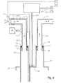
- Figure 4 is a schematic sectional view of an alternative embodiment of the sulfur loading assembly shown in Figure 1 .
- a movable tanker 11 is illustrated below a sulfur loading assembly 13. Movable tanker 11 is preferably supported on a chassis and wheel assembly allowing movable tanker 11 to be moved into position for receiving a load from sulfur loading assembly 13. As will readily be appreciated by those skilled in the art, although tanker 11 is illustrated as a railroad tanker, movable tanker 11 can also be a tanker that is towed behind a vehicle such as an eighteen wheeler.
- An opening 15 is preferably formed on an upper surface of movable tanker 11 for receiving a load from loading assembly 13.
- opening 15 is positioned beneath loading assembly 13 for receiving a payload into tanker 11.
- An opening guard G is formed around opening 15 on an upper surface of tanker 11.
- Loading assembly 13 includes a feed line 19 for supplying a supply of product from a product source S.
- Loading assembly 13 also preferably includes a ventilation line 21 that is in fluid communication with a ventilation system V.
- Ventilation line 21 preferably receives fumes from tanker 11 during the loading process of the supply into tanker 11.
- Ventilation line 21 communicates fumes from tanker 11 and conveys the fumes to the ventilation system V so that the fumes are either collected for disposal or recirculated within other processing equipment.
- source S provides a supply of molten sulfur to tanker 11.
- ventilation line 21 preferably carries the sulfur fumes to a ventilation system V so that fumes are collected for disposal or recirculated to source S.
- Loading assembly 13 preferably includes an extendable loader 23 that selectively moves between raised and lowered positions ( Figures 2 and 3 ).
- a support structure 17 preferably supports feed and ventilation lines 19, 21 as well as wench 25 and extendable loader 23.
- a controller 29 is positioned in communication, such as pneumatic or electrical, with control line 27 adjacent a platform 31.
- control line 27 adjacent a platform 31.
- an operator can operate wench 25 with controller 29 from a position spaced-apart from tanker 11 and loading assembly 13 when standing upon platform 31.
- Extendable loader 23 includes a hood 33 that is raised and lowered relative to support structure 17.
- Hood 33 covers and encloses opening 15 of tanker 11.
- Hood 33 helps in the collection of fumes F being collected through ventilation line 21 during the loading process.
- a support mount 35 is connected to hood 33.
- a support line 37 connects to support mount 35 and extends upward to wench 25.
- Support line 37 can be a cable, a chain, or any suitable line for lifting and lowering extendable loader 23 with wench 25.
- Hood assembly 33 also preferably includes an inlet opening 39 and an outlet opening 41.
- Inlet opening 39 is in fluid communication with source S for receiving liquid L from source S through feed line 19, and outlet opening 41 is in fluid communication with ventilation line 21 for transferring fumes F from tanker 11 during the loading process.
- ventilation line 21 for transferring fumes F from tanker 11 during the loading process.
- Extendable loader 23 includes a supply telescoping conduit 43 that connects to hood 33 at inlet opening 39. Extendable loader 23 also preferably includes a vent telescoping conduit 45 connecting to hood 33 at outlet opening 41. As best illustrated in Figures 2 and 3 , telescoping conduits 43 and 45 allow extendable loader 23 to be raised and lowered between the lowered or extended position shown in Figure 2 and the raised or retracted position shown in Figure 3 .
- Supply telescoping conduit 43 preferably includes a supply inner conduit 47 and a supply outer conduit 49.
- Supply outer conduit 49 preferably slides up and down relative to supply inner conduit 47.
- Supply inner conduit 47 rigidly connects to feed line 19 in a manner such that supply inner conduit 47 does not move up and down relative to support structure 17.
- vent telescoping conduit 45 also includes vent inner conduit 51 and vent outer conduit 53.
- Vent inner conduit 51 connects to ventilation line 21 in a manner such that vent inner conduit 51 does not move relative to support structure 17 when extendable loader 23 is moved between its raised and lowered positions.
- Vent outer conduit 53 preferably slides telescopingly relative to vent inner conduit 51 when wench 25 raises and lowers hood 33.
- Supply outer conduit 49 preferably extends below hood 33 so that supply outer conduit 49 extends below opening 15 when extendable loader 23 is in its lowered position relative to support structure 17. With supply outer conduit 49 positioned below opening 15, liquid L advantageously flows into tanker 11 without as much liquid spilling due to missing opening 15.
- Extendable loader 23 preferably includes a sensor 55 extending below hood 33 adjacent supply outer conduit 49. Sensor 55 preferably extends below hood 33 into tanker 11 through opening 15 such that sensor 55 detects when fluid L reaches a predetermined level within tanker 11.
- a sensor line 57 is in communication with sensor 55 and extends upward to support structure 17.
- Sensor line 57 is preferably in electrical communication with control line 27 so that a predetermined signal can be communicated to a level control valve (LCV) 18 when fluid level L reaches a predetermined level within tanker 11 to alert the operator of the fluid level L within tanker 11 during the product transfer process.
- the predetermined signal can be communicated to LCV 18, for automatically stopping flow from source S, and to activate a siren for recognition by the operator. The operator can manually stop flow if necessary.
- an empty tanker 11 is positioned underneath support structure 17 such that opening 15 is located below loading assembly 13.
- an operator uses controller 29 to lower extendable loader 23 from its raised position shown in Figure 1 and Figure 3 to its lowered position shown in Figure 2 .
- controller 29 conveys electrical or pneumatic signals to wench 25 to engage wench 25 for lowering hood 33 into position on opening 15.
- Liquid L is transferred from source S through feed line 19 into supply inner conduit 47 and through supply outer conduit 49 into tanker 11.
- Liquid L is transferred from source S after opening a manual valve upstream of LCV 18, and operating LCV 18 via a pneumatic button control valve of LCV 18.
- the signal to LCV 18 is electrical.
- LCV 18 will automatically cease the conveyance of liquid L from source S.
- the operator who is standing on platform 31 can also cease the conveyance of liquid L from source S with a push button controller to actuate LCV 18, or through a manual valve 60 positioned upstream of LCV 18.
- the operator Upon turning off the supply of liquid from source S when liquid level L reaches the predetermined level within tanker 11, the operator uses controller 29 to activate wench 25 in order to raise hood 33 of extendable loader 23 relative to opening 15.
- extendable loader 23 When extendable loader 23 is in its raised position as shown in Figure 3 , the operator can move tanker 11 away from loading assembly 13.
- Loading assembly 13 advantageously provides the operator with a safe process by which to load liquid L into tanker 11 from source S without being exposed to as many fumes F and the possibility of tripping over guard G while trying to position loading assembly 23 into position relative to opening 15.
- Loading assembly 13 eliminates the use of flexible hoses and swiveling joints that need replacement due to the corrosiveness and the heat of molten sulfur. Having stationary supply and vent inner conduits 47, 51 allows the operator to select metals such as stainless steel, or coatings on the interior surfaces that are more resistant to corrosion under heat. The operator can also select metals such as stainless steel, or coating on the surfaces of supply and vent outer conduits 49, 53 and hood 33 that are exposed to the molten sulfur and its fumes.
- a heating jacket 71 surrounds a portion of feed line 19' and supply inner conduit 47'.
- Heating jacket 71 preferably conveys a heating liquid H while liquid L is conveyed from source S to supply inner conduit 47'.
- Heating liquid H carried within heating jacket 71 advantageously helps to maintain the temperature of liquid L being carried within feed line 19' so that liquid L does not decrease to a temperature such that it would change phases.
- a seal 73 is positioned between heating jacket 71 and supply inner conduit 47' so that heating liquid H can be guided to a recovery collector R.
- heating liquid H can be a substance such as steam for maintaining of temperature of liquid L above its temperature upon which liquid L would change phases to a solid.
- Heating jacket 71 can also be utilized around ventilation line 21'.
- a plurality of metal plates 75 are preferably mounted to the exterior of a lower portion of supply inner conduit 47'. Metal plate 75 helped to reduce the amount of liquid L that can splash up to the inner phase of supply inner conduit 47' and supply outer conduit 49'.
- a seal 77 is positioned above metal plate 75.
- An annular cover 79 is formed on an upper portion of supply outer conduit 49'. Annular cover 79 preferably extends radially inward relative to supply outer conduit 49' toward the outer surface of inner conduit 47. Annular cover 79 preferably engages seal 77 when extendable loader 23' is in its lowered position.
- seal 77 also help to reduce the contact that seal 77 has with liquid L as liquid L is being conveyed into tanker 11'.
- seal 77 comprises a rubberized material.
- seal 77 and metal plate 75 are also positioned around vent inner conduit 51' to engage in annular cover 79 extending radially inward from vent outer conduit 53.
- Seal 77 also helps to reduce the amount of fumes F escaping loading assembly 13' around the physical interface of vent inner conduit and vent outer conduit 51', 53' so that fumes F are conveyed in the desired manner through vent outer conduit 53' and to vent inner conduit 51' so that fumes are properly carried to ventilation line 21' where fumes F can be disposed of in a predetermined manner.
- Hoses, sensors, and sensor cables get damaged due to the movement of the prior art assemblies, as well as due to the heat and chemicals these parts interact with during operation. Such damages disable the level control and vacuum systems necessary for the safety of the operator.
- Loading assembly 13 helps to reduce such damage and also creates an environment where the operator is farther away from the heat and fumes from the molten sulfur.
Landscapes
- Engineering & Computer Science (AREA)
- Mechanical Engineering (AREA)
- Loading And Unloading Of Fuel Tanks Or Ships (AREA)
- Feeding, Discharge, Calcimining, Fusing, And Gas-Generation Devices (AREA)
Abstract
Description
- The present invention relates generally to a product conveyance assembly, and more specifically to an apparatus for transferring a chemical substance to a movable tanker.
- Loading arm assemblies are utilized for the transfer of chemicals from a processing plant to a tanker for transportation. Loading arm assemblies that are used for the loading of molten chemicals, such as, sulfur have numerous drawbacks associated with the safety to the operator and the reliability of the equipment. In prior art assemblies, loading arms included flexible non-metallic tubing, or tubing that was maneuverable do to swivel joints, that was manually pulled and positioned over an opening of tanker. A vacuum piping system was often associated with the maneuverable loading arms for collecting some of the fumes emanating from the molten sulfur being loaded into the tanker.
- Molten sulfur often caused corrosive damage to the non-metallic tubing or piping, and to the swivel joints that needed to be replaced repeated. Moreover, the operator had to push and pull the prior art loading arms while moving about the upper surface of the tanker. This exposed the operator awkward and often dangerous situations while handling the molten sulfur loading arms. The operator had to negotiate curved tankers with protuberances and guard assemblies formed on the tanker surface around the tanker opening, and the operator was exposed to the heat associated with the molten sulfur being transferred to the tanker the operator was walking upon. Furthermore, the operator was often exposed to the fumes from the chemicals emanating from within the tanker during the loading process while engaging and disengaging the loading arm with the tanker.
- A chemical loading system is used for loading a molten chemical into a tanker. The chemical loading system includes a source supplying a molten chemical and a tanker for receiving the molten chemical. The chemical loading system has a stationary feed line supplying a chemical from the source. An extendable loader has a feed passage that is in fluid communication with the feed line. The extendable loader has a retracted position and an extended position relative to the feed line. The feed passage is adapted to have at least a portion thereof inside the tanker when in the extendable loader is in the extended position. A hoist assembly selectively extends and retracts the extendable loader assembly between the retracted and extended positions.
- The molten chemical is typically molten sulfur. Feed seals are typically positioned between the feed line and the feed passage. The chemical loading system can also include a heating jacket mounted to the feed line. The heating jacket carries a heating fluid to keep the molten chemical from solidifying in the feed line. The heating fluid can be steam, and a heating fluid recovery unit in fluid communication with the heating jacket collects and recovers the heating fluid when the heating fluid exits the heating jacket.
- The chemical loading system of can also include a platform positioned adjacent the tanker. The platform is also positioned away from the extendable loader assembly. A controller is positioned on the platform and is in communication with the hoist assembly for selectively extending and retracting the extendable loader assembly.
- The extendable loader assembly of the chemical loading system can also include a ventilation passage in fluid communication with the interior of the tanker when the extendable loader is in its extended position. The ventilation passage extends parallel to the feed passage. The ventilation passage moves in unison with the feed passage when the extendable loader assembly is moved between its extended and retracted positions. The chemical loading system can also include a ventilation line in fluid communication with the ventilation passage. The ventilation line is in fluid communication with a collection unit that collects the fumes from the molten chemical.
- A loading assembly is used for loading molten sulfur into a tanker. The loading assembly includes a hood adapted to cover an opening of the tanker. A pair of telescoping conduits are attached to the hood. One of the telescoping conduits is for flowing the molten sulfur into the tanker. The other of the telescoping conduits is for ventilating fumes from the molten sulfur. Each of the pair of telescoping conduits have an upper portion and a lower portion. The lower portions being movable in unison with the hood between a raised position and a lowered position.
- The loading assembly can also have seals positioned between the upper and lower portions of the telescoping conduits. A plurality of metal plates may be connected to the outer surface of a lower end of each of the upper portions of the telescoping conduits. The lower conduits can receive the upper conduits when the lower portions and the hood are moved to the raised position. The telescoping conduits can extend parallel to each other from the hood.
- The loading assembly can also include a driven wench that selectively raises the hood between the raised and lowered positions. The loading assembly can also include a liquid sensor extending downward from the hood that is adapted to determine when the molten sulfur reaches a predetermined level within the tanker.
- A method for loading molten sulfur into a tanker includes the step of providing an extendable loader having a feed passage. The extendable loader is movable by a remotely controlled wench between a retracted position and an extended position. The method then includes positioning a tanker beneath the extendable loader for receiving a molten sulfur. The feed passage is extended to the extended position so that least a portion thereof is inside the tanker. The molten sulfur is conveyed into the tanker from a sulfur source through a stationary feed line in fluid communication with the feed passage. The feed passage is retracted to the retracted position. The tanker is moved from beneath the extendable loader.
- The method can also include the step of providing a ventilation passage in fluid communication with the interior of the tanker when the extendable loader is in its extended position. The fumes emanating from the molten sulfur within the tanker are then collected with the ventilation passage.
-
Figure 1 is a schematic view of a movable tanker positioned beneath a sulfur loading assembly constructed in accordance with the present invention. -
Figure 2 is a schematic sectional view of the movable tanker and the sulfur loading assembly ofFigure 1 when viewed along line 2-2, with the sulfur loading assembly in its lowered positioned. -
Figure 3 is a schematic sectional view of the movable tanker and the sulfur loading assembly ofFigure 1 when viewed along line 2-2, with the sulfur loading assembly in its raised positioned. -
Figure 4 is a schematic sectional view of an alternative embodiment of the sulfur loading assembly shown inFigure 1 . - Referring to
Figure 1 , amovable tanker 11 is illustrated below asulfur loading assembly 13.Movable tanker 11 is preferably supported on a chassis and wheel assembly allowingmovable tanker 11 to be moved into position for receiving a load fromsulfur loading assembly 13. As will readily be appreciated by those skilled in the art, althoughtanker 11 is illustrated as a railroad tanker,movable tanker 11 can also be a tanker that is towed behind a vehicle such as an eighteen wheeler. - An
opening 15 is preferably formed on an upper surface ofmovable tanker 11 for receiving a load from loadingassembly 13. In the preferred embodiment opening 15 is positioned beneath loadingassembly 13 for receiving a payload intotanker 11. An opening guard G is formed around opening 15 on an upper surface oftanker 11. -
Loading assembly 13 includes afeed line 19 for supplying a supply of product from a product sourceS. Loading assembly 13 also preferably includes aventilation line 21 that is in fluid communication with a ventilation systemV. Ventilation line 21 preferably receives fumes fromtanker 11 during the loading process of the supply intotanker 11.Ventilation line 21 communicates fumes fromtanker 11 and conveys the fumes to the ventilation system V so that the fumes are either collected for disposal or recirculated within other processing equipment. - In the preferred embodiment, source S provides a supply of molten sulfur to
tanker 11. When molten sulfur is the product being supplied,ventilation line 21 preferably carries the sulfur fumes to a ventilation system V so that fumes are collected for disposal or recirculated to source S. -
Loading assembly 13 preferably includes anextendable loader 23 that selectively moves between raised and lowered positions (Figures 2 and3 ). Awench 25, which can be motor driven or pneumatically driven, is connected toextendable loader 23 via acontrol line 27 to raise and lowerextendable loader 23 between its raised and lowered positions. Asupport structure 17 preferably supports feed andventilation lines wench 25 andextendable loader 23. - Referring to
Figures 2 and3 , acontroller 29 is positioned in communication, such as pneumatic or electrical, withcontrol line 27 adjacent aplatform 31. As will be readily appreciated by those skilled in the art, an operator can operatewench 25 withcontroller 29 from a position spaced-apart fromtanker 11 andloading assembly 13 when standing uponplatform 31. -
Extendable loader 23 includes ahood 33 that is raised and lowered relative to supportstructure 17.Hood 33 covers and encloses opening 15 oftanker 11.Hood 33 helps in the collection of fumes F being collected throughventilation line 21 during the loading process. Asupport mount 35 is connected tohood 33. Asupport line 37 connects to supportmount 35 and extends upward to wench 25.Support line 37 can be a cable, a chain, or any suitable line for lifting and loweringextendable loader 23 withwench 25. -
Hood assembly 33 also preferably includes aninlet opening 39 and anoutlet opening 41.Inlet opening 39 is in fluid communication with source S for receiving liquid L from source S throughfeed line 19, andoutlet opening 41 is in fluid communication withventilation line 21 for transferring fumes F fromtanker 11 during the loading process. As will be readily appreciated by those skilled in the art, during the loading process, liquid L is transferred throughfeed line 19, and inlet opening 39 intotanker 11 where liquid L accumulates in a lower portion oftanker 11. -
Extendable loader 23 includes asupply telescoping conduit 43 that connects tohood 33 atinlet opening 39.Extendable loader 23 also preferably includes avent telescoping conduit 45 connecting tohood 33 atoutlet opening 41. As best illustrated inFigures 2 and3 ,telescoping conduits extendable loader 23 to be raised and lowered between the lowered or extended position shown inFigure 2 and the raised or retracted position shown inFigure 3 . -
Supply telescoping conduit 43 preferably includes a supplyinner conduit 47 and a supplyouter conduit 49. Supplyouter conduit 49 preferably slides up and down relative to supplyinner conduit 47. Supplyinner conduit 47 rigidly connects to feedline 19 in a manner such that supplyinner conduit 47 does not move up and down relative to supportstructure 17. - As will be readily appreciated by those skilled in the art, when
extendable loader 23 is moved between its upper and lower positions, supplyinner conduit 47 remains stationary relative to supportstructure 17 andwench 25, while supplyouter conduit 49 moves withhood 33. Similarly, venttelescoping conduit 45 also includes ventinner conduit 51 and ventouter conduit 53. Ventinner conduit 51 connects toventilation line 21 in a manner such that ventinner conduit 51 does not move relative to supportstructure 17 whenextendable loader 23 is moved between its raised and lowered positions. Ventouter conduit 53 preferably slides telescopingly relative to ventinner conduit 51 whenwench 25 raises and lowershood 33. - Supply
outer conduit 49 preferably extends belowhood 33 so that supplyouter conduit 49 extends below opening 15 whenextendable loader 23 is in its lowered position relative to supportstructure 17. With supplyouter conduit 49 positioned below opening 15, liquid L advantageously flows intotanker 11 without as much liquid spilling due to missingopening 15. -
Extendable loader 23 preferably includes asensor 55 extending belowhood 33 adjacent supplyouter conduit 49.Sensor 55 preferably extends belowhood 33 intotanker 11 throughopening 15 such thatsensor 55 detects when fluid L reaches a predetermined level withintanker 11. Asensor line 57 is in communication withsensor 55 and extends upward to supportstructure 17.Sensor line 57 is preferably in electrical communication withcontrol line 27 so that a predetermined signal can be communicated to a level control valve (LCV) 18 when fluid level L reaches a predetermined level withintanker 11 to alert the operator of the fluid level L withintanker 11 during the product transfer process. The predetermined signal can be communicated toLCV 18, for automatically stopping flow from source S, and to activate a siren for recognition by the operator. The operator can manually stop flow if necessary. - In operation, an
empty tanker 11 is positioned underneathsupport structure 17 such thatopening 15 is located below loadingassembly 13. While standing uponplatform 31 an operator usescontroller 29 to lowerextendable loader 23 from its raised position shown inFigure 1 andFigure 3 to its lowered position shown inFigure 2 . While usingcontroller 29 to control the position ofextendable loader 23 relative to supportstructure 17,controller 29 conveys electrical or pneumatic signals to wench 25 to engagewench 25 for loweringhood 33 into position on opening 15. Liquid L is transferred from source S throughfeed line 19 into supplyinner conduit 47 and through supplyouter conduit 49 intotanker 11. Liquid L is transferred from source S after opening a manual valve upstream ofLCV 18, and operatingLCV 18 via a pneumatic button control valve ofLCV 18. The signal toLCV 18 is electrical. As liquid L accumulates withintanker 11, the level of liquid withintanker 11 begins to rise toward supplyouter conduit 49 andsensor 55. When liquid level L reachessensor 55, an electrical signal is communicated throughsensor line 57 andcontrol line 27 toLCV 18 andcontroller 29 onplatform 31. Preferably,LCV 18 will automatically cease the conveyance of liquid L from source S. However, the operator who is standing onplatform 31 can also cease the conveyance of liquid L from source S with a push button controller to actuateLCV 18, or through amanual valve 60 positioned upstream ofLCV 18. - While liquid L is accumulating within
tanker 11, fumes F are communicated through opening 15 into ventouter conduit 53.Hood 33 helps to guide films F into ventouter conduit 53. Fumes F convey through ventouter conduit 53 into ventinner conduit 51 and on toventilation line 21 for disposal as predetermined by the operator. - Upon turning off the supply of liquid from source S when liquid level L reaches the predetermined level within
tanker 11, the operator usescontroller 29 to activatewench 25 in order to raisehood 33 ofextendable loader 23 relative toopening 15. Whenextendable loader 23 is in its raised position as shown inFigure 3 , the operator can movetanker 11 away from loadingassembly 13. As will be readily appreciated by those skilled in the art, the operator has been able to control the loading process of the liquid L from source S without having to manually position the feed lines and ventilation lines relative to opening 15 as had been done in the past.Loading assembly 13 advantageously provides the operator with a safe process by which to load liquid L intotanker 11 from source S without being exposed to as many fumes F and the possibility of tripping over guard G while trying to position loadingassembly 23 into position relative toopening 15. -
Loading assembly 13 eliminates the use of flexible hoses and swiveling joints that need replacement due to the corrosiveness and the heat of molten sulfur. Having stationary supply and ventinner conduits outer conduits hood 33 that are exposed to the molten sulfur and its fumes. - Referring to
Figure 4 , an alternative embodiment of loading assembly 13' is shown. In the alternative embodiment shown inFigure 4 , aheating jacket 71 surrounds a portion of feed line 19' and supply inner conduit 47'.Heating jacket 71 preferably conveys a heating liquid H while liquid L is conveyed from source S to supply inner conduit 47'. Heating liquid H carried withinheating jacket 71 advantageously helps to maintain the temperature of liquid L being carried within feed line 19' so that liquid L does not decrease to a temperature such that it would change phases. Aseal 73 is positioned betweenheating jacket 71 and supply inner conduit 47' so that heating liquid H can be guided to a recovery collector R. As will be readily appreciated by those skilled in the art, heating liquid H can be a substance such as steam for maintaining of temperature of liquid L above its temperature upon which liquid L would change phases to a solid.Heating jacket 71 can also be utilized around ventilation line 21'. - In the embodiment shown in
Figure 4 , a plurality ofmetal plates 75 are preferably mounted to the exterior of a lower portion of supply inner conduit 47'.Metal plate 75 helped to reduce the amount of liquid L that can splash up to the inner phase of supply inner conduit 47' and supply outer conduit 49'. In the embodiment shown inFigure 4 , aseal 77 is positioned abovemetal plate 75. Anannular cover 79 is formed on an upper portion of supply outer conduit 49'.Annular cover 79 preferably extends radially inward relative to supply outer conduit 49' toward the outer surface ofinner conduit 47.Annular cover 79 preferably engagesseal 77 when extendable loader 23' is in its lowered position. As will be readily appreciated by those skilled in the art,metal plates 75 also help to reduce the contact that seal 77 has with liquid L as liquid L is being conveyed into tanker 11'. In the preferred embodiment, seal 77 comprises a rubberized material. In the embodiment shown inFigure 4 , seal 77 andmetal plate 75 are also positioned around vent inner conduit 51' to engage inannular cover 79 extending radially inward from ventouter conduit 53.Seal 77 also helps to reduce the amount of fumes F escaping loading assembly 13' around the physical interface of vent inner conduit and vent outer conduit 51', 53' so that fumes F are conveyed in the desired manner through vent outer conduit 53' and to vent inner conduit 51' so that fumes are properly carried to ventilation line 21' where fumes F can be disposed of in a predetermined manner. - Hoses, sensors, and sensor cables get damaged due to the movement of the prior art assemblies, as well as due to the heat and chemicals these parts interact with during operation. Such damages disable the level control and vacuum systems necessary for the safety of the operator.
Loading assembly 13 helps to reduce such damage and also creates an environment where the operator is farther away from the heat and fumes from the molten sulfur. - The description and figures are merely illustrative of various embodiments. While the invention has been shown in only some of its forms, it should be apparent to those skilled in the art that it is not so limited, but is susceptible to various changes without departing from the scope of the invention.
- Preferred features of embodiments of the invention are set out in the following clauses.
- 1. A chemical loading system for loading a molten chemical into a tanker, comprising:
- a source supplying a molten chemical;
- a tanker for receiving the molten chemical;
- a stationary feed line supplying a chemical from the source;
- an extendable Ioader having a feed passage in fluid communication with the feed line, the extendable loader having a retracted position and an extended position relative to the feed line, the feed passage being adapted to have at least a portion thereof inside the tanker when in the extendable loader is in the extended position; and
- a hoist assembly that selectively extends and retracts the extendable loader assembly between the retracted and extended positions.
- 2. The chemicals loading system of clause 1, further comprising:
- a platform positioned adjacent the tanker and away from the extendable loader assembly; and
- a controller positioned on the platform that is in communication with the hoist assembly for selectively extending and retracting the extendable loader assembly.
- 3. The chemical loading system of clause 1, further comprising feed seals positioned between the feed line and the feed passage.
- 4. The chemical loading system of clause 1, further comprising a heating jacket mounted to the feed line, the heating jacket carrying a heating fluid to keep the molten chemical from solidifying in the feed line.
- 5. The chemical loading system of clause 4, wherein the beating fluid is steam.
- 6. The chemical loading system of clause 4, further comprising: a heating fluid recovery unit in fluid communication with the heating jacket for collecting and recovering the heating fluid when the heating fluid exits the heating jacket.
- 7. The chemical loading system of clause 1, wherein the extendable loader assembly further comprises a ventilation passage in fluid communication with the interior of the tanker when the extendable loader is in its extended position.
- 8. The chemical loading system of clause 7, wherein the ventilation passage extends parallel to the feed passage.
- 9. The chemical loading system of clause 7, wherein the ventilation passage moves in unison with the feed passage when the extendable loader assembly is moved between its extended and retracted positions.
- 10. The chemical loading system of clause 7, further comprising a ventilation line in fluid communication with the ventilation passage, the ventilation line being in fluid communication with a collection unit that collects the fumes from the molten chemical.
- 11. The chemical loading system of clause 1, further comprising a hood with an opening through which the feed passage extends, the hood enclosing an opening of the tanker when the extendable loader assembly is in its extended position.
- 12. A loading assembly for loading a molten sulfur into a tanker, comprising:
- a hood adapted to cover an opening of a tanker;
- a pair of telescoping conduits attached to the hood, one of the telescoping conduits for flowing a molten sulfur into the tanker, the other of the telescoping conduits ventilating fumes from the molten sulfur, each of the pair of telescoping conduits having an upper portion and a lower portion, the lower portions being movable in unison with the hood between a raised position and a lowered position.
- 13. The loading assembly of clause 12, further comprising seals positioned between the upper and lower portions of the telescoping conduits.
- 14. The loading assembly of clause 12, further comprising a plurality of metal plates connected to the outer surface of a lower end of each of the upper portions of the telescoping conduits.
- 15. The loading assembly of clause 12, wherein the lower conduits receive the upper conduits when the lower portions and the hood are movsd to the raised position.
- 16. The loading assembly of clause 12, wherein the telescoping conduits extend parallel to each other from the hood,
- 17. The loading assembly of clause 12, further comprising a driven wench that selectively raises the hood between the raised and lowered positions.
- 18. The loading assembly of clause 12, further comprising a liquid sensor extending downward from the hood that is adapted to determine when the molten sulfur reaches a predetermined level within the tanker.
- 19. A method for loading molten sulfur into a tanker, comprising:
- providing an extendable loader having a feed passage, the extendable loader being movable by a remotely controlled driven wench between a retracted position and an extended position,
- positioning a tanker beneath the extendable loader for receiving a molten sulfur;
- extending the feed passage to the extended position so that least a portion thereof is inside the tanker;
- conveying the molten sulfur into the tanker from a sulfur source through a stationary feed line in fluid communication with the feed passage;
- retracting the feed passage to the retracted position; and then
- moving the tanker from beneath the extendable loader.
- 20. The method of
clause 19, further comprising providing a ventilation passage in fluid communication with the interior of the tanker when the extendable loader is in its extended position; and then
collecting fumes emanating from the molten sulfur within the tanker with the ventilation passage.
Claims (15)
- A loading assembly for loading a molten sulfur into a tanker, comprising:a hood adapted to cover an opening of a tanker;a pair of telescoping conduits attached to the hood, one of the telescoping conduits for flowing a molten sulfur into the tanker, the other of the telescoping conduits ventilating fumes from the molten sulfur, each of the pair of telescoping conduits having an upper portion and a lower portion, the lower portions being movable in unison with the hood between a raised position and a lowered position.
- The loading assembly of claim 1, further comprising: seals positioned between the upper and lower portions of the telescoping conduits OR
a plurality of metal plates connected to the outer surface of a lower end of each of the upper portions of the telescoping conduits. - The loading assembly of claim 1, wherein the lower conduits receive the upper conduits when the lower portions and the hood are moved to the raised position.
- The loading assembly of claim 1, wherein the telescoping conduits extend parallel to each other from the hood.
- The loading assembly of claim 1, further comprising a driven wench that selectively raises the hood between the raised and lowered positions.
- The loading assembly of claim 1, further comprising a liquid sensor extending downward from the hood that is adapted to determine when the molten sulfur reaches a predetermined level within the tanker.
- A chemical loading system for loading a molten chemical into a tanker, comprising:a source supplying a molten chemical;a stationary feed line supplying a chemical from the source;an extendable loader having a feed passage in fluid communication with the feed line, the extendable loader having a retracted position and an extended position relative to the feed line, the feed passage being adapted to have at least a portion thereof inside a tanker when in the extendable loader is in the extended position; anda hoist assembly that selectively extends and retracts the extendable loader assembly between the retracted and extended positions.
- The chemical loading system of claim 7, further comprising:a platform configured to have a tanker positioned adjacent thereto and positioned away from the extendable loader assembly; anda controller positioned on the platform that is in communication with the hoist assembly for selectively extending and retracting the extendable loader assembly.
- The chemical loading system of claim 7, further comprising: feed seals positioned between the feed line and the feed passage; OR
a heating jacket mounted to the feed line, the heating jacket carrying a heating fluid to keep the molten chemical from solidifying in the feed line. - The chemical loading system of claim 7: further comprising a heating jacket mounted to the feed line, the heating jacket carrying a heating fluid to keep the molten chemical from solidifying in the feed line wherein the heating fluid is steam; OR further comprising a heating jacket mounted to the feed line, the heating jacket carrying a heating fluid to keep the molten chemical from solidifying in the feed line and_a heating fluid recovery unit in fluid communication with the heating jacket for collecting and recovering the heating fluid when the heating fluid exits the heating jacket.
- The chemical loading system of claim 7, wherein the extendable loader assembly further comprises a ventilation passage in fluid communication with the interior of the tanker when the extendable loader is in its extended position.
- The chemical loading system of claim 11: wherein the ventilation passage extends parallel to the feed passage; OR
wherein the ventilation passage moves in unison with the feed passage when the extendable loader assembly is moved between its extended and retracted positions;
OR
further comprising a ventilation line in fluid communication with the ventilation passage, the ventilation line being in fluid communication with a collection unit that collects the fumes from the molten chemical. - The chemical loading system of claim 7, further comprising a hood with an opening through which the feed passage extends, the hood enclosing an opening of the tanker when the extendable loader assembly is in its extended position.
- A method for loading molten sulfur into a tanker, comprising:providing an extendable loader having a feed passage, the extendable loader being movable by a remotely controlled driven wench between a retracted position and an extended position,positioning a tanker beneath the extendable loader for receiving a molten sulfur;extending the feed passage to the extended position so that at least a portion thereof is inside the tanker;conveying the molten sulfur into the tanker from a sulfur source through a stationary feed line in fluid communication with the feed passage;retracting the feed passage to the retracted position; and then moving the tanker from beneath the extendable loader.
- A method for loading molten sulfur into a tanker, comprising:providing a hood adapted to cover an opening of a tanker;providing a pair of telescoping conduits attached to the hood, one of the telescoping conduits for flowing a molten sulfur into the tanker, the other of the telescoping conduits ventilating fumes from the molten sulfur, each of the pair of telescoping conduits having an upper portion and a lower portion, the lower portions being movable in unison with the hood between a raised position and a lowered position;positioning a tanker beneath the hood;moving the lower portions of the pair of telescoping conduits and the hood to the lowered position;conveying the molten sulfur into the tanker from a sulfur source through the one of the telescoping conduits for flowing molten sulfur into the tanker;moving the lower portions of the pair of telescoping conduits and the hood to the raised position; and thenmoving the tanker from beneath the hood.
Applications Claiming Priority (2)
| Application Number | Priority Date | Filing Date | Title |
|---|---|---|---|
| US11/455,532 US7958913B2 (en) | 2006-06-19 | 2006-06-19 | Sulfur loading apparatus |
| EP07794398A EP2032498A2 (en) | 2006-06-19 | 2007-04-27 | Sulfur loading apparatus |
Related Parent Applications (1)
| Application Number | Title | Priority Date | Filing Date |
|---|---|---|---|
| EP07794398.3 Division | 2007-04-27 |
Publications (1)
| Publication Number | Publication Date |
|---|---|
| EP2682361A1 true EP2682361A1 (en) | 2014-01-08 |
Family
ID=38719487
Family Applications (2)
| Application Number | Title | Priority Date | Filing Date |
|---|---|---|---|
| EP20130187349 Withdrawn EP2682361A1 (en) | 2006-06-19 | 2007-04-27 | Sulfur loading apparatus |
| EP07794398A Withdrawn EP2032498A2 (en) | 2006-06-19 | 2007-04-27 | Sulfur loading apparatus |
Family Applications After (1)
| Application Number | Title | Priority Date | Filing Date |
|---|---|---|---|
| EP07794398A Withdrawn EP2032498A2 (en) | 2006-06-19 | 2007-04-27 | Sulfur loading apparatus |
Country Status (4)
| Country | Link |
|---|---|
| US (3) | US7958913B2 (en) |
| EP (2) | EP2682361A1 (en) |
| NO (1) | NO20090280L (en) |
| WO (1) | WO2007149146A2 (en) |
Families Citing this family (6)
| Publication number | Priority date | Publication date | Assignee | Title |
|---|---|---|---|---|
| US7659722B2 (en) | 1999-01-28 | 2010-02-09 | Halliburton Energy Services, Inc. | Method for azimuthal resistivity measurement and bed boundary detection |
| US7958913B2 (en) | 2006-06-19 | 2011-06-14 | Saudi Arabian Oil Company | Sulfur loading apparatus |
| RU2394270C1 (en) | 2006-07-11 | 2010-07-10 | Хэллибертон Энерджи Сервисиз, Инк. | Modular instrument unit for geo-control |
| EP2361394B1 (en) | 2008-11-24 | 2022-01-12 | Halliburton Energy Services, Inc. | A high frequency dielectric measurement tool |
| WO2011022012A1 (en) | 2009-08-20 | 2011-02-24 | Halliburton Energy Services, Inc. | Fracture characterization using directional electromagnetic resistivity measurements |
| JP6376335B2 (en) * | 2014-03-26 | 2018-08-22 | パナソニックIpマネジメント株式会社 | Discharge device |
Citations (3)
| Publication number | Priority date | Publication date | Assignee | Title |
|---|---|---|---|---|
| US3831644A (en) * | 1971-08-18 | 1974-08-27 | Knapsack Ag | Filling nozzle and installation for filling drums with liquid yellow phosphorus |
| FR2234220A1 (en) * | 1973-06-19 | 1975-01-17 | Peters Ag Claudius | Hot bitumen loading of road tankers - using telescopic filling pipe |
| GB1439291A (en) * | 1973-06-18 | 1976-06-16 | Fmc Corp | Fluid transfer apparatus |
Family Cites Families (12)
| Publication number | Priority date | Publication date | Assignee | Title |
|---|---|---|---|---|
| US2979087A (en) * | 1956-08-22 | 1961-04-11 | Ruhrchemie Ag | Device for the fluid flow connecting of stationary conduits and portable fluid containers such as tank cars |
| BE789834A (en) | 1971-10-11 | 1973-04-09 | D Comp Gen | SUSPENDED ROD FOR HANDLING FLUID OR SIMILAR PRODUCTS |
| US4180272A (en) * | 1978-09-15 | 1979-12-25 | Compagnie d'Etudes et de Realisations de Cybernetique | Seal for sealing between two telescopic tubes and sealing device using such seal |
| US4224968A (en) * | 1978-12-08 | 1980-09-30 | Compagnie D'etudes Et De Realisations De Cybernetique Industrielle | Tank filling installations |
| US5184654A (en) * | 1991-06-18 | 1993-02-09 | Dover Corporation | Vapor recovery sealing devices |
| US6099616A (en) * | 1998-08-31 | 2000-08-08 | Owens Corning Fiberglas Technology, Inc. | Method for recovering vapors during the dispensing of a bituminous product |
| JP2000128324A (en) * | 1998-10-26 | 2000-05-09 | Tsukasa Kogyo Kk | Device for loading powdery and granular material |
| US6698463B2 (en) * | 2001-12-04 | 2004-03-02 | Lemmon Tracey T | System and method for controlling a hazardous fluid distribution facility |
| US7255840B2 (en) * | 2003-06-26 | 2007-08-14 | Praxair Technology, Inc. | Autothermal reactor and method for production of synthesis gas |
| US6932123B1 (en) * | 2004-07-19 | 2005-08-23 | Marathon Ashland Petroluem Llc | Drop tube assembly |
| US7958913B2 (en) | 2006-06-19 | 2011-06-14 | Saudi Arabian Oil Company | Sulfur loading apparatus |
| DE202006019847U1 (en) * | 2006-10-17 | 2007-04-12 | Jahndorf Christian | Loading assembly for bulk fluids rests on electrically powered rail-mounted moving platform with telescopic down-pipe |
-
2006
- 2006-06-19 US US11/455,532 patent/US7958913B2/en not_active Expired - Fee Related
-
2007
- 2007-04-27 WO PCT/US2007/010282 patent/WO2007149146A2/en not_active Ceased
- 2007-04-27 EP EP20130187349 patent/EP2682361A1/en not_active Withdrawn
- 2007-04-27 EP EP07794398A patent/EP2032498A2/en not_active Withdrawn
-
2009
- 2009-01-19 NO NO20090280A patent/NO20090280L/en not_active Application Discontinuation
-
2010
- 2010-12-23 US US12/977,330 patent/US8118067B2/en not_active Expired - Fee Related
-
2012
- 2012-01-19 US US13/353,364 patent/US8424573B2/en active Active
Patent Citations (3)
| Publication number | Priority date | Publication date | Assignee | Title |
|---|---|---|---|---|
| US3831644A (en) * | 1971-08-18 | 1974-08-27 | Knapsack Ag | Filling nozzle and installation for filling drums with liquid yellow phosphorus |
| GB1439291A (en) * | 1973-06-18 | 1976-06-16 | Fmc Corp | Fluid transfer apparatus |
| FR2234220A1 (en) * | 1973-06-19 | 1975-01-17 | Peters Ag Claudius | Hot bitumen loading of road tankers - using telescopic filling pipe |
Also Published As
| Publication number | Publication date |
|---|---|
| US8118067B2 (en) | 2012-02-21 |
| US8424573B2 (en) | 2013-04-23 |
| US20110088807A1 (en) | 2011-04-21 |
| WO2007149146A2 (en) | 2007-12-27 |
| US7958913B2 (en) | 2011-06-14 |
| NO20090280L (en) | 2009-03-13 |
| WO2007149146A3 (en) | 2008-02-21 |
| US20080011370A1 (en) | 2008-01-17 |
| US20120111442A1 (en) | 2012-05-10 |
| EP2032498A2 (en) | 2009-03-11 |
Similar Documents
| Publication | Publication Date | Title |
|---|---|---|
| US8424573B2 (en) | Sulfur loading apparatus | |
| US6932123B1 (en) | Drop tube assembly | |
| US5293887A (en) | Robotic tank cleaning system and method | |
| EP3643414B1 (en) | An ultra-high-pressure water jetting (uhpwj) hydro-blasting cleaning system for surfaces | |
| US10974292B2 (en) | Device for removing catalyst and other material from refinery and petrochemical reactors and other vessels | |
| US9174812B2 (en) | System for delivering solid particulate matter for loading | |
| US9371216B2 (en) | Pipeline pig extractor and transport apparatus with wind guard | |
| US12151270B1 (en) | Method and apparatus, including hose reel, for cleaning an oil and gas well riser assembly with multiple tools simultaneously | |
| US4945955A (en) | Hazardous waste removal devices | |
| CN102730426B (en) | For powder and/or the transmitting device of granular material | |
| US20120279537A1 (en) | Tank Cleaning Unit | |
| EP2912229B1 (en) | Multipurpose tool for oil spill control, preferably offshore | |
| CN207108460U (en) | A kind of automatic oiling dolly based on grinding fuel tank | |
| US10174564B1 (en) | Method and apparatus for cleaning an oil and gas well riser assembly with multiple tools simultaneously | |
| US9187891B2 (en) | System and apparatus for evacuation of contaminated fluids from flexible hulled vessels | |
| CN103282598B (en) | Device for handling hoses of a working well for a drilling rig | |
| CN109821386B (en) | Sulfur loading tail gas recovery and treatment system and its tail gas treatment device | |
| JP2015525673A (en) | Cleaning system for cleaning tanks, etc. | |
| US20020134739A1 (en) | Manually controlled skimming of industrial oil contaminants | |
| CN103072088B (en) | Small-caliber elbow and rust removing system in small-caliber elbow containing long straight tube section | |
| CN108791445B (en) | Tubular product conveyer with flexible supporting component | |
| CN207826312U (en) | Tank loading and conveying device | |
| EP1568888B1 (en) | Apparatus and method for the retrieval of radioactive material from an enclosure vault | |
| CN216336581U (en) | Oil unloading pipe pry of intelligent control safety oil unloading system of gas station | |
| SU338466A1 (en) | INSTALLATION FOR HYDRAULIC TRANSPORTATION OF SPRAYED MATERIALS |
Legal Events
| Date | Code | Title | Description |
|---|---|---|---|
| PUAI | Public reference made under article 153(3) epc to a published international application that has entered the european phase |
Free format text: ORIGINAL CODE: 0009012 |
|
| AC | Divisional application: reference to earlier application |
Ref document number: 2032498 Country of ref document: EP Kind code of ref document: P |
|
| AK | Designated contracting states |
Kind code of ref document: A1 Designated state(s): AT BE BG CH CY CZ DE DK EE ES FI FR GB GR HU IE IS IT LI LT LU LV MC MT NL PL PT RO SE SI SK TR |
|
| 17P | Request for examination filed |
Effective date: 20140708 |
|
| RBV | Designated contracting states (corrected) |
Designated state(s): AT BE BG CH CY CZ DE DK EE ES FI FR GB GR HU IE IS IT LI LT LU LV MC MT NL PL PT RO SE SI SK TR |
|
| STAA | Information on the status of an ep patent application or granted ep patent |
Free format text: STATUS: THE APPLICATION HAS BEEN WITHDRAWN |
|
| 18W | Application withdrawn |
Effective date: 20150421 |