EP2682347B1 - Container assembly - Google Patents
Container assembly Download PDFInfo
- Publication number
- EP2682347B1 EP2682347B1 EP13182332.0A EP13182332A EP2682347B1 EP 2682347 B1 EP2682347 B1 EP 2682347B1 EP 13182332 A EP13182332 A EP 13182332A EP 2682347 B1 EP2682347 B1 EP 2682347B1
- Authority
- EP
- European Patent Office
- Prior art keywords
- stacking
- container
- container assembly
- protrusion
- assembly
- Prior art date
- Legal status (The legal status is an assumption and is not a legal conclusion. Google has not performed a legal analysis and makes no representation as to the accuracy of the status listed.)
- Active
Links
Images

Classifications
-
- B—PERFORMING OPERATIONS; TRANSPORTING
- B65—CONVEYING; PACKING; STORING; HANDLING THIN OR FILAMENTARY MATERIAL
- B65D—CONTAINERS FOR STORAGE OR TRANSPORT OF ARTICLES OR MATERIALS, e.g. BAGS, BARRELS, BOTTLES, BOXES, CANS, CARTONS, CRATES, DRUMS, JARS, TANKS, HOPPERS, FORWARDING CONTAINERS; ACCESSORIES, CLOSURES, OR FITTINGS THEREFOR; PACKAGING ELEMENTS; PACKAGES
- B65D21/00—Nestable, stackable or joinable containers; Containers of variable capacity
- B65D21/02—Containers specially shaped, or provided with fittings or attachments, to facilitate nesting, stacking, or joining together
- B65D21/0209—Containers specially shaped, or provided with fittings or attachments, to facilitate nesting, stacking, or joining together stackable or joined together one-upon-the-other in the upright or upside-down position
- B65D21/0217—Containers with a closure presenting stacking elements
- B65D21/0223—Containers with a closure presenting stacking elements the closure and the bottom presenting local co-operating elements, e.g. projections and recesses
-
- E—FIXED CONSTRUCTIONS
- E05—LOCKS; KEYS; WINDOW OR DOOR FITTINGS; SAFES
- E05C—BOLTS OR FASTENING DEVICES FOR WINGS, SPECIALLY FOR DOORS OR WINDOWS
- E05C19/00—Other devices specially designed for securing wings, e.g. with suction cups
- E05C19/10—Hook fastenings; Fastenings in which a link engages a fixed hook-like member
- E05C19/12—Hook fastenings; Fastenings in which a link engages a fixed hook-like member pivotally mounted around an axis
- E05C19/14—Hook fastenings; Fastenings in which a link engages a fixed hook-like member pivotally mounted around an axis with toggle action
-
- A—HUMAN NECESSITIES
- A45—HAND OR TRAVELLING ARTICLES
- A45C—PURSES; LUGGAGE; HAND CARRIED BAGS
- A45C13/00—Details; Accessories
- A45C13/18—Devices to prevent theft or loss of purses, luggage or hand carried bags
Definitions
- This invention relates, in general, to a container assembly according to the preamble of claim 1, and deals more particularly with a container assembly having a unique, utilitarian pattern formed on opposing sides of the container assembly, whereby the pattern provides increased stacking and attachment-point advantages.
- Containers of various shapes, sizes and configurations have been employed to accommodate all manner of storage and transportation needs.
- containers primarily utilized to transport items, it is often necessary to protect these items from impact and / or environmental damage, as well as to make the container suitable for stacking and storage during transportation.
- known transportation containers typically utilize similar patterns on opposing sides of the container, oftentimes being mirror images of each other.
- known containers also typically employ patterns which are limited to being uni-directional in their stacking ability and frequently employ patterns that contain 'hard', or sharp edges.
- US 2006/0254946 discloses a container assembly comprising first and second portions having respective outer surfaces with different stacking patterns adapted for engagement.
- the general object of the present invention to provide a container assembly with a novel stacking profile defined on opposing sides of the container.
- the profile formed on one side of the container is not the same as the inter-connecting profile defined on the opposing side of the container.
- the defined profiles of the present invention enable a bi-directional stacking capability, as well as having edges of the defined profiles that are more resistant to wear and damage.
- the stacking patterns of the container assembly enable the bi-directional stacking of one of the container assemblies with another of the container assemblies.
- the present invention concerns a container assembly as claimed in claim 1.
- An embodiment of the inventive container assembly for the storage and transport of goods includes a first portion having an interior with a substantially flat interior bottom surface.
- the assembly further includes a second portion pivotally connected to the first portion.
- the first portion has an outer surface that includes a first stacking pattern and the second portion has an outer surface that includes a second stacking pattern different from the first stacking portion and configured to engage the first stacking pattern enabling the container assembly to be bi-directionally stacked on another of the container assemblies.
- FIGS. 1 , 3 - 6 illustrate a container assembly according an embodiment of the present invention.
- the container assembly 2 includes structural profiles formed on opposing sides of the container.
- one side of the container 2 defines a first stacking profile 4 that includes a series of wavy ribs or ridges 6, extending from one lateral side of the container 8, to the other 10.
- the wavy ridges 6 define a series of wave-like profiles 12 that create laterally extending channels or valleys 14 therebetween.
- the raised wavy ridges 6 undulate in a sinusoidal fashion along their lateral axis, thereby forming a series of apexes and depressions along the length of the ridges 6.
- the wavy ridges 6 are oriented on the container 2 such that the apexes of adjacent wavy ridges 6 are opposed to one another, thus creating a repeating series of wide and narrow, i.e., convex and concave, sections in the valleys 14.
- the wave-like configuration of ridges 6 is an important aspect of the present invention.
- the wave like shape of the ridges 6 avoids sharp bends, which act as stress concentrators.
- the wave shape maximizes structural strength and integrity of the ridges 6.
- the wave-like shape is formed from a series of tangent arcs.
- the shape of the ridges 6 may also be derived from sinusoidal and quadratic equations.
- the top surface of the ridges 6 have an area equal to the area of the valleys 14 between the ridges 6. This configuration maximizes the strength of the structure by equalizing the cross-sectional "up” and "down” areas.
- an opposing side of the container 2 assembly defines a second stacking profile 16 comprising a series of generally rounded protrusions 18 which may be donut shaped as shown or, alternatively puck shaped.
- the protrusions 18 are dimensioned so as to fit within the wide (i.e., rounded) sections of the valleys 14 to facilitate stacking.
- the protrusions may be puck-shaped, the donut shape with its raised inner area or hole is preferable.
- This shape increases the flat surface area inside the container, i.e., on the container floor or bottom.
- the increased flat surface area creates a stable platform for goods placed within the container.
- the inner flat surface area also provides a convenient point to attach a fastener to, for example, secure cargo to the interior bottom floor of the container. This surface allows for the installation of fasteners without the fasteners touching the ground or interfering with corresponding stacking ridges 6.
- the profiles defined on opposing sides of the container assembly enable the stacking of one container assembly atop another container assembly.
- the stacking profiles of the present invention permit the bi-directional stacking of one container assembly atop another. That is, the stacking profiles 4, 16 created on opposing sides of the container assembly are capable of stacking one such container assembly atop another, even when the two container assemblies (and, thus, their stacking patterns) are oriented at 90° from one another, i.e., bi-directional stacking.
- the profiles allow cases to be stacked regardless of their footprint so that smaller cases can be stacked on larger cases and vice versa.
- both of the stacking patterns defined on the container assembly are formed with rounded edges.
- the present invention facilitates an easier integration between the donut-like protrusions 18 of one container assembly with the wide sections of the wavy valleys 14 of another container assembly.
- the rounded edges of the stacking profiles make them less susceptible to damage caused by drop-impact, or the like.
- the side edges 12 of the wavy ridges 14 of the container assembly are formed to exhibit a 5° draft. In this manner, various accessories may be more easily and more securely attached to locations between adjacent wavy ridges (i.e., locations at least partially attached within the wavy valleys 14).
- the donut-like protrusions are cut or segmented. These segmented protrusions 20 are segmented by a cut 22 which prevents water entrapment when the case assembly 2 is inverted, further increases the flat surface area inside the container 2, and reduces the entrapment of dirt and debris, facilitating easy removal of the same. While the cuts in the donuts can be in various orientations, it is preferable that they be perpendicular to the length of the container 2. This configuration results in a more rigid container wall 24 than through parallel cuts. Empirical evidence depicting this is presented in FIGS. 4 and 5 .
- the inventive container 2 features partially cut or segmented perimeter protrusions 26. These partial cuts create C-shaped perimeteral protrusions, which, along with the fully cut protrusions 22 creates a channel having a centerline 28. As will be appreciated, the channels allow for the attachment of various objects having a member configured to engage the channels.
- the inventive container 2 may also include casters 27. These are depicted in FIG. 2 and, as will be readily appreciated, allow the container 2 to be rolled during transport.
- the casters 27 are located within a puck or donut 18 such that sides 29 of the donut 18 protect the casters 27.
- FIGS. 6 - 9E a latch/locking mechanism 40 not forming part of the invention is also shown. As most clearly shown in Figures 1 and 2 , the locking mechanism 40 is centrally located with respect to the housing of the container assembly 2, and provides increased effectiveness, security and ease of manipulation.
- the locking mechanism 40 includes a fixed base 42, a guide 43 and a hinged leaf 44.
- the hinged leaf 44 is free to pivot about a pin 46 that is secured within a bracket 48.
- the bracket 48 is secured to the container 2 through the use of conventional fasteners (not shown).
- the hinged leaf 44 includes a free distal end terminating in a hooked portion 50 shaped to receive a portion of the fixed base 42 when the mechanism 40 is secured.
- hinged leaf 44 within the bracket 48 is an important aspect of the locking mechanism.
- the hinged leaf 44 completely covers the fasteners used to secured the bracket 48 to the container 2. This prevents removal of the fasteners to bypass the lock and gain access to the interior of the container 2.
- the base 42 is similarly secured to the container 2.
- a lever 52 of the base 42 covers the fasteners when the lock is secured to prevent access to the case interior.
- the base 42 includes a lever 52, which pivots up and down about a base bracket 58 to raise or lower a u-shaped engagement surface 54.
- the u-shaped engagement surface 54 is configured to engage and pull down on the hooked portion 50 of the hinged leaf 44 to secure a top or lid of a container 2 to a base portion.
- the lever 52 terminates with a tab 56 that is used to raise or lower the lever 52.
- the path and movement of the engagement surface 54 are defined and limited by the guide 43.
- the base bracket 58 includes padlock eyes 60 which, as will be appreciated, receives a u-shaped shackle of a padlock 70 ( FIGS. 7 , 8A, 8B, 9A, 9B ).
- the eyes 60 are shaped such that they include a sloped or angled shackle surface 62, which includes a shackle divot 64 sized to accommodate the lock shackle ( FIG. 9C ).
- This surface 62 and divot 64 are important in that they cause a padlock to slide down via gravity toward the container and into the divot 64. This allows the padlock to be complete recessed within a valley or channel of the outer case surface during shipping. This, in turn, minimizes potential damage to the container, the lock mechanism, the lock, and any adjacent cargo.
- the locking mechanism 40 is unlocked by first unlocking and removing the padlock.
- the tab 56 and lever 52 are then pulled upward and outward so that the engagement surface 54 disengages with the hooked portion 50 of the hinged leaf 44 allowing the container 2 to be opened.
- the container 2 is unlocked the lid may be closed without the risk of self-locking. That is, the engagement portion 54 is not in a position to engage the hooked portion 50. This is an important safety and operational benefit of the locking mechanism.
Landscapes
- Engineering & Computer Science (AREA)
- Mechanical Engineering (AREA)
- Stackable Containers (AREA)
Description
- This invention relates, in general, to a container assembly according to the preamble of claim 1, and deals more particularly with a container assembly having a unique, utilitarian pattern formed on opposing sides of the container assembly, whereby the pattern provides increased stacking and attachment-point advantages.
- Containers of various shapes, sizes and configurations have been employed to accommodate all manner of storage and transportation needs. Typically, in the case of containers primarily utilized to transport items, it is often necessary to protect these items from impact and / or environmental damage, as well as to make the container suitable for stacking and storage during transportation.
- Towards this end, it has been known to define structural profiles on the surfaces of containers, in order to provide a pattern, or matrix, by which other like containers may be stacked with one another during transportation.
- Moreover, the stacking patterns of known transportation containers typically utilize similar patterns on opposing sides of the container, oftentimes being mirror images of each other. In addition, known containers also typically employ patterns which are limited to being uni-directional in their stacking ability and frequently employ patterns that contain 'hard', or sharp edges.
-
US 2006/0254946 discloses a container assembly comprising first and second portions having respective outer surfaces with different stacking patterns adapted for engagement. - With the forgoing problems and concerns in mind, it is the general object of the present invention to provide a container assembly with a novel stacking profile defined on opposing sides of the container. In one preferred embodiment, the profile formed on one side of the container is not the same as the inter-connecting profile defined on the opposing side of the container. Moreover, the defined profiles of the present invention enable a bi-directional stacking capability, as well as having edges of the defined profiles that are more resistant to wear and damage.
- It is an object of the present invention to provide a container assembly.
- It is another object of the present invention to provide a container assembly having stacking patterns formed on opposing sides of the container.
- It is another object of the present invention that the stacking patterns of the container assembly enable the bi-directional stacking of one of the container assemblies with another of the container assemblies.
- It is another object of the present invention to provide a container assembly whereby the stacking patterns on opposing sides of the container are different from one another.
- It is yet another object of the present invention to provide a container assembly having stacking patterns that are more resistant to wear and damage.
- It is yet another object of the present invention to provide a stacking pattern for a container assembly that includes integrated wheels, wherein the integrated wheels do not interfere with the bi-directional stacking ability of the container.
- According to a first aspect, the present invention concerns a container assembly as claimed in claim 1.
- An embodiment of the inventive container assembly for the storage and transport of goods includes a first portion having an interior with a substantially flat interior bottom surface. The assembly further includes a second portion pivotally connected to the first portion. The first portion has an outer surface that includes a first stacking pattern and the second portion has an outer surface that includes a second stacking pattern different from the first stacking portion and configured to engage the first stacking pattern enabling the container assembly to be bi-directionally stacked on another of the container assemblies.
- These and other objectives of the present invention, and their preferred embodiments, shall become clear by consideration of the specification, claims and drawings taken as a whole.
-
-
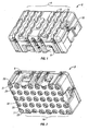
FIG. 1 is a top perspective view of an embodiment of the container assembly of the present invention. -
FIG. 2 is a bottom perspective view of a container assembly not forming part of the invention. -
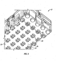
FIG. 3 is a bottom perspective view of an embodiment of the container assembly of the present invention. -
FIG. 4 is a side view of the embodiment ofFIG. 3 -
FIG. 5 is a side view of an alternative to the embodiment ofFIG. 4 -
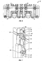
FIG. 6 is a front view of the container assembly according to the embodiments ofFIGS. 1 and3 . -
FIG. 7 is a enlarged, perspective view of a latch assembly not forming part of the invention for use with the container assembly ofFIGS. 1 or3 . -
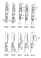
FIG. 8A - 8E are front, perspective views of the latch assembly ofFIG. 7 graphically illustrating operation of the latch assembly. -
FIG. 9A - 9E are front, perspective view of the latch assembly ofFIG. 7 graphically illustrating operation of the latch assembly. -
FIGS. 1 ,3 - 6 illustrate a container assembly according an embodiment of the present invention. As shown inFIGS. 1 and 2 , thecontainer assembly 2 includes structural profiles formed on opposing sides of the container. In particular, one side of thecontainer 2 defines a first stacking profile 4 that includes a series of wavy ribs or ridges 6, extending from one lateral side of thecontainer 8, to the other 10. When located side-by-side with one another, the wavy ridges 6 define a series of wave-like profiles 12 that create laterally extending channels orvalleys 14 therebetween. - As shown, the raised wavy ridges 6 undulate in a sinusoidal fashion along their lateral axis, thereby forming a series of apexes and depressions along the length of the ridges 6. The wavy ridges 6 are oriented on the
container 2 such that the apexes of adjacent wavy ridges 6 are opposed to one another, thus creating a repeating series of wide and narrow, i.e., convex and concave, sections in thevalleys 14. - This wave-like configuration of ridges 6 is an important aspect of the present invention. In particular, the wave like shape of the ridges 6 avoids sharp bends, which act as stress concentrators. Thus, the wave shape maximizes structural strength and integrity of the ridges 6. Preferably, the wave-like shape is formed from a series of tangent arcs. As will be appreciated, the shape of the ridges 6 may also be derived from sinusoidal and quadratic equations.
- Further, it is also preferable that the top surface of the ridges 6 have an area equal to the area of the
valleys 14 between the ridges 6. This configuration maximizes the strength of the structure by equalizing the cross-sectional "up" and "down" areas. - Turning now to
FIG. 2 , an opposing side of thecontainer 2 assembly defines asecond stacking profile 16 comprising a series of generallyrounded protrusions 18 which may be donut shaped as shown or, alternatively puck shaped. As will be appreciated, theprotrusions 18 are dimensioned so as to fit within the wide (i.e., rounded) sections of thevalleys 14 to facilitate stacking. - While the protrusions may be puck-shaped, the donut shape with its raised inner area or hole is preferable. This shape increases the flat surface area inside the container, i.e., on the container floor or bottom. The increased flat surface area creates a stable platform for goods placed within the container. The inner flat surface area also provides a convenient point to attach a fastener to, for example, secure cargo to the interior bottom floor of the container. This surface allows for the installation of fasteners without the fasteners touching the ground or interfering with corresponding stacking ridges 6.
- It will therefore be readily appreciated that the profiles defined on opposing sides of the container assembly enable the stacking of one container assembly atop another container assembly. Moreover, given the structural relationship between the
protrusions 18 and thewavy valleys 14, the stacking profiles of the present invention permit the bi-directional stacking of one container assembly atop another. That is, thestacking profiles 4, 16 created on opposing sides of the container assembly are capable of stacking one such container assembly atop another, even when the two container assemblies (and, thus, their stacking patterns) are oriented at 90° from one another, i.e., bi-directional stacking. Further, the profiles allow cases to be stacked regardless of their footprint so that smaller cases can be stacked on larger cases and vice versa. - It is another aspect of the present invention that both of the stacking patterns defined on the container assembly are formed with rounded edges. By doing so, the present invention facilitates an easier integration between the donut-
like protrusions 18 of one container assembly with the wide sections of thewavy valleys 14 of another container assembly. Moreover, the rounded edges of the stacking profiles make them less susceptible to damage caused by drop-impact, or the like. - It is yet another important aspect of the present invention that the
side edges 12 of thewavy ridges 14 of the container assembly are formed to exhibit a 5° draft. In this manner, various accessories may be more easily and more securely attached to locations between adjacent wavy ridges (i.e., locations at least partially attached within the wavy valleys 14). - Turning now to
FIG. 3 , the donut-like protrusions are cut or segmented. Thesesegmented protrusions 20 are segmented by acut 22 which prevents water entrapment when thecase assembly 2 is inverted, further increases the flat surface area inside thecontainer 2, and reduces the entrapment of dirt and debris, facilitating easy removal of the same. While the cuts in the donuts can be in various orientations, it is preferable that they be perpendicular to the length of thecontainer 2. This configuration results in a morerigid container wall 24 than through parallel cuts. Empirical evidence depicting this is presented inFIGS. 4 and 5 . - Referring back to
FIG. 3 , theinventive container 2 features partially cut or segmentedperimeter protrusions 26. These partial cuts create C-shaped perimeteral protrusions, which, along with the fully cutprotrusions 22 creates a channel having acenterline 28. As will be appreciated, the channels allow for the attachment of various objects having a member configured to engage the channels. - The
inventive container 2 may also includecasters 27. These are depicted inFIG. 2 and, as will be readily appreciated, allow thecontainer 2 to be rolled during transport. Preferably, thecasters 27 are located within a puck ordonut 18 such that sides 29 of thedonut 18 protect thecasters 27. - Turning now to
FIGS. 6 - 9E , a latch/locking mechanism 40 not forming part of the invention is also shown. As most clearly shown inFigures 1 and 2 , thelocking mechanism 40 is centrally located with respect to the housing of thecontainer assembly 2, and provides increased effectiveness, security and ease of manipulation. - More specifically, the
locking mechanism 40 includes a fixedbase 42, aguide 43 and a hingedleaf 44. As shown, the hingedleaf 44 is free to pivot about apin 46 that is secured within abracket 48. Thebracket 48 is secured to thecontainer 2 through the use of conventional fasteners (not shown). The hingedleaf 44 includes a free distal end terminating in a hookedportion 50 shaped to receive a portion of the fixedbase 42 when themechanism 40 is secured. - The configuration of hinged
leaf 44 within thebracket 48 is an important aspect of the locking mechanism. In particular, when the hookedportion 50 is engaged by thebase 42, the hingedleaf 44 completely covers the fasteners used to secured thebracket 48 to thecontainer 2. This prevents removal of the fasteners to bypass the lock and gain access to the interior of thecontainer 2. Referring now toFIGS. 8C and 8E , thebase 42 is similarly secured to thecontainer 2. Here, alever 52 of the base 42 covers the fasteners when the lock is secured to prevent access to the case interior. - The
base 42 includes alever 52, which pivots up and down about abase bracket 58 to raise or lower au-shaped engagement surface 54. Theu-shaped engagement surface 54 is configured to engage and pull down on the hookedportion 50 of the hingedleaf 44 to secure a top or lid of acontainer 2 to a base portion. Thelever 52 terminates with atab 56 that is used to raise or lower thelever 52. The path and movement of theengagement surface 54 are defined and limited by theguide 43. - Moreover, the
base bracket 58 includespadlock eyes 60 which, as will be appreciated, receives a u-shaped shackle of a padlock 70 (FIGS. 7 ,8A, 8B, 9A, 9B ). Significantly, theeyes 60 are shaped such that they include a sloped orangled shackle surface 62, which includes ashackle divot 64 sized to accommodate the lock shackle (FIG. 9C ). Thissurface 62 anddivot 64 are important in that they cause a padlock to slide down via gravity toward the container and into thedivot 64. This allows the padlock to be complete recessed within a valley or channel of the outer case surface during shipping. This, in turn, minimizes potential damage to the container, the lock mechanism, the lock, and any adjacent cargo. - In use, and as shown in
FIGS. 8A - 8E and 9A - 9E , thelocking mechanism 40 is unlocked by first unlocking and removing the padlock. Thetab 56 andlever 52 are then pulled upward and outward so that theengagement surface 54 disengages with the hookedportion 50 of the hingedleaf 44 allowing thecontainer 2 to be opened. As shown inFIG. 9E , then thecontainer 2 is unlocked the lid may be closed without the risk of self-locking. That is, theengagement portion 54 is not in a position to engage the hookedportion 50. This is an important safety and operational benefit of the locking mechanism. - While the invention has been described with reference to the preferred embodiments, it will be understood by those skilled in the art that various obvious changes may be made, and equivalents may be substituted for elements thereof, without departing from the essential scope of the present invention. Therefore, it is intended that the invention not be limited to the particular embodiments disclosed, but that the invention includes all embodiments falling within the scope of the appended claims.
Claims (5)
- A container assembly for the storage and transport of goods, said assembly (2) comprising:a first portion having an interior;a second portion pivotally connected to said first portion;wherein that said first portion has an outer surface that includes a first stacking pattern (4) formed thereon, said first stacking pattern being defined by a plurality of first stacking elements, said first stacking elements each having first lateral sidewalls defining a first peripheral shape of said first stacking elements;said second portion has an outer surface that includes a second stacking pattern (16) formed thereon, said second stacking pattern being defined by a plurality of second stacking elements, said second stacking elements each having second lateral sidewalls defining a second peripheral shape of said second stacking elements;said first peripheral shape of at least one of said first stacking elements is different from said second peripheral shape of at least one of said second stacking elements;said second stacking pattern is configured to engage said first stacking pattern enabling said container assembly to be bi-directionally stacked on another of said container assemblies; and
characterized in thatsaid first stacking pattern includes at least one protrusion (20), said protrusion being substantially annular in shape and being comprised of two c-shaped arcs, said arcs facing another and having a channel (22) therebetween, said channel facilitating cleaning of dirt and debris from said protrusion. - The container assembly of claim 1, wherein said at least one protrusion (20), is puck shaped.
- The container assembly of claim 1, wherein said annular protrusion (20) has an inner surface that extends inward and forms a portion of an interior bottom surface of said first portion.
- The container assembly of claim 1, wherein said at least one protrusion is a plurality of substantially annular protrusions at least one of which includes a caster (27).
- The container assembly of claim 1, wherein said at least one annular protrusion is a plurality of substantially annular protrusions, said protrusions being arranged in an array so that said channels between said c-shaped arcs of said individual protrusions are in alignment forming a elongated channel configured for attachment of an object.
Applications Claiming Priority (3)
| Application Number | Priority Date | Filing Date | Title |
|---|---|---|---|
| US2119508P | 2008-01-15 | 2008-01-15 | |
| US12/353,490 US8789699B2 (en) | 2008-01-15 | 2009-01-14 | Container assembly |
| EP09702146.3A EP2238039B1 (en) | 2008-01-15 | 2009-01-15 | Container assembly |
Related Parent Applications (4)
| Application Number | Title | Priority Date | Filing Date |
|---|---|---|---|
| WOPCT/US2009/000320 Previously-Filed-Application | 2009-01-15 | ||
| EP09702146.3 Division | 2009-01-15 | ||
| PCT/US2009/000320 Previously-Filed-Application WO2009091602A2 (en) | 2008-01-15 | 2009-01-15 | Container assembly |
| EP09702146.3A Division EP2238039B1 (en) | 2008-01-15 | 2009-01-15 | Container assembly |
Publications (2)
| Publication Number | Publication Date |
|---|---|
| EP2682347A1 EP2682347A1 (en) | 2014-01-08 |
| EP2682347B1 true EP2682347B1 (en) | 2015-07-22 |
Family
ID=40849727
Family Applications (2)
| Application Number | Title | Priority Date | Filing Date |
|---|---|---|---|
| EP13182332.0A Active EP2682347B1 (en) | 2008-01-15 | 2009-01-15 | Container assembly |
| EP09702146.3A Active EP2238039B1 (en) | 2008-01-15 | 2009-01-15 | Container assembly |
Family Applications After (1)
| Application Number | Title | Priority Date | Filing Date |
|---|---|---|---|
| EP09702146.3A Active EP2238039B1 (en) | 2008-01-15 | 2009-01-15 | Container assembly |
Country Status (4)
| Country | Link |
|---|---|
| US (1) | US8789699B2 (en) |
| EP (2) | EP2682347B1 (en) |
| ES (2) | ES2547833T3 (en) |
| WO (1) | WO2009091602A2 (en) |
Families Citing this family (45)
| Publication number | Priority date | Publication date | Assignee | Title |
|---|---|---|---|---|
| US8602217B2 (en) | 2009-12-11 | 2013-12-10 | The Stanley Works Israel Ltd. | Container |
| US20120006837A1 (en) * | 2010-07-12 | 2012-01-12 | Environmental Container Systems, D/B/A Ecs Composites | Hybrid stacking system for containers |
| US8413833B1 (en) | 2010-09-03 | 2013-04-09 | TCF Composites, LLC | Ruggedized composite rack mount transport case |
| US8333275B2 (en) | 2011-01-25 | 2012-12-18 | Store-It-More, Llc | Portable jar holder |
| US10179547B2 (en) * | 2013-05-24 | 2019-01-15 | Stellar Industries, Inc. | Side pack with channels |
| US9027755B2 (en) * | 2013-08-22 | 2015-05-12 | Marlon Jones | Food container stacking device and system |
| GB2529532A (en) * | 2014-06-16 | 2016-02-24 | Leafield Environmental Ltd | Rotationally moulded cases |
| DK2990346T3 (en) * | 2014-08-28 | 2020-02-03 | Makel Mekanik Muehendislik Anonim Sirketi | STACKABLE CASE |
| US10442568B1 (en) | 2014-08-29 | 2019-10-15 | Matthew A. Summers | Nesting container and nesting container assembly |
| US9550605B1 (en) | 2014-08-29 | 2017-01-24 | Matthew A. Summers | Nesting container assembly |
| US9802741B2 (en) | 2014-12-10 | 2017-10-31 | Becklin Holdings, Inc. | Container with padlock mount |
| EP3265391B1 (en) | 2015-03-06 | 2022-05-04 | Keter Home and Garden Products Ltd. | Container assemblies |
| JP6580421B2 (en) | 2015-08-25 | 2019-09-25 | 株式会社トプコン | carrying case |
| USD1000113S1 (en) | 2015-08-28 | 2023-10-03 | Summers Matthew A | Container |
| USD808164S1 (en) | 2015-08-28 | 2018-01-23 | Matthew A. Summers | Container |
| US9758276B2 (en) | 2015-09-23 | 2017-09-12 | Raytheon Company | Method and apparatus for ultra-clean seeker transportation and storage |
| US11267119B2 (en) | 2015-12-14 | 2022-03-08 | Milwaukee Electric Tool Corporation | Storage device system |
| USD812375S1 (en) * | 2016-04-21 | 2018-03-13 | Pith Products Llc | Stackable container |
| CN110893610A (en) | 2016-05-02 | 2020-03-20 | 凯特尔塑料有限公司 | Utility module and coupling mechanism |
| WO2018213560A1 (en) * | 2017-05-17 | 2018-11-22 | Milwaukee Electric Tool Corporation | Storage device system |
| WO2019028041A1 (en) | 2017-07-31 | 2019-02-07 | Milwaukee Electric Tool Corporation | STORAGE DEVICE SYSTEM |
| USD896517S1 (en) | 2017-08-09 | 2020-09-22 | Keter Plastic Ltd. | Tool box |
| USD904830S1 (en) | 2017-12-14 | 2020-12-15 | Dometic Sweden Ab | Soft bag cooler |
| AU201717676S (en) | 2017-12-14 | 2018-01-16 | Dometic Sweden Ab | Zip Puller |
| CN111615481B (en) | 2017-12-20 | 2022-11-04 | 凯特尔塑料有限公司 | Trolley and mechanical braking system thereof |
| WO2019147801A2 (en) | 2018-01-24 | 2019-08-01 | Milwaukee Electric Tool Corporation | Tool storage |
| IL257294A (en) | 2018-02-01 | 2018-03-29 | Milwaukee Electric Tool Corp | Connectable box |
| IL259990B (en) | 2018-06-13 | 2022-07-01 | Keter Home & Garden Products Ltd | Utility connectivity system |
| IL260225A (en) | 2018-06-24 | 2018-07-31 | Keter Plastic Ltd | Hand truck |
| USD967693S1 (en) | 2019-02-26 | 2022-10-25 | Keter Plastic Ltd. | Mounting plate |
| USD898320S1 (en) | 2019-02-26 | 2020-10-06 | Keter Plastic Ltd. | Dolly |
| IL265964A (en) | 2019-04-11 | 2019-07-31 | Milwaukee Electric Tool Corp | Racking system and coupler |
| USD919296S1 (en) | 2019-05-31 | 2021-05-18 | Keter Plastic Ltd. | Crate |
| USD923935S1 (en) | 2019-05-31 | 2021-07-06 | Keter Plastic Ltd. | Toolbox |
| USD917977S1 (en) | 2019-05-31 | 2021-05-04 | Keter Plastic Ltd. | Cooler |
| IL269564B2 (en) | 2019-09-23 | 2023-11-01 | Keter Home & Garden Products Ltd | Work donkey |
| WO2021211581A1 (en) | 2020-04-14 | 2021-10-21 | Milwaukee Electric Tool Corporation | Storage device with multi-function lid |
| CN115335192A (en) * | 2020-04-14 | 2022-11-11 | 米沃奇电动工具公司 | Storage device with multifunctional cover |
| US11672317B2 (en) | 2020-07-02 | 2023-06-13 | Case-Mate, Inc. | Waterproof case |
| US11884456B2 (en) | 2020-09-25 | 2024-01-30 | Techtronic Cordless Gp | Tool storage system |
| US11459005B2 (en) | 2020-10-27 | 2022-10-04 | Raytheon Company | Ultra-clean manually-actuated clamping brake |
| KR102513804B1 (en) * | 2020-11-26 | 2023-03-28 | 주식회사 코렌텍 | Sterilized Container for Surgical Instrument |
| US12312126B2 (en) * | 2021-11-03 | 2025-05-27 | Meridian International Co., Ltd | Stacked toolbox system |
| US11738914B2 (en) | 2021-11-18 | 2023-08-29 | Yeti Coolers, Llc | Container and latching system |
| US20230278191A1 (en) * | 2022-03-04 | 2023-09-07 | Meridian International Co., Ltd | Connection structure of module, storage box and storage box assembly |
Family Cites Families (11)
| Publication number | Priority date | Publication date | Assignee | Title |
|---|---|---|---|---|
| US3524415A (en) * | 1968-11-14 | 1970-08-18 | Gen Motors Corp | Plastic shipping tray |
| US3616943A (en) * | 1969-09-17 | 1971-11-02 | Grace W R & Co | Stacking system |
| DE7725336U1 (en) | 1977-08-16 | 1977-11-17 | Panick Fa Johann | Stackable container |
| US4883251A (en) * | 1987-06-09 | 1989-11-28 | Manas Jorge F | Container for making ice cubes |
| US5184836A (en) * | 1990-10-26 | 1993-02-09 | Rubbermaid Commercial Products Inc. | Refuse container having stacking and nesting handles |
| CA2103830C (en) * | 1992-08-19 | 2005-05-17 | Gerald M. Syrek | Stackable container for premoistened wipes |
| US5676251A (en) * | 1994-08-22 | 1997-10-14 | The Coca-Cola Company | Food service kit and method for using |
| ES2128138T3 (en) * | 1996-01-18 | 1999-05-01 | Perstorp Plastic Syst Ab | FOLDING CONTAINER. |
| US6478158B2 (en) * | 1998-09-30 | 2002-11-12 | Rayovac Corporation | Battery package with multiple support compartments |
| EP1389590A1 (en) | 2002-08-14 | 2004-02-18 | Omni-Pac Ekco GmbH & Co. KG Verpackungsmittel | Food packaging with locking elements |
| US7537119B2 (en) | 2005-05-12 | 2009-05-26 | Environmental Container Systems | Stackable container apparatus and methods |
-
2009
- 2009-01-14 US US12/353,490 patent/US8789699B2/en active Active
- 2009-01-15 WO PCT/US2009/000320 patent/WO2009091602A2/en not_active Ceased
- 2009-01-15 ES ES13182332.0T patent/ES2547833T3/en active Active
- 2009-01-15 ES ES09702146.3T patent/ES2437338T3/en active Active
- 2009-01-15 EP EP13182332.0A patent/EP2682347B1/en active Active
- 2009-01-15 EP EP09702146.3A patent/EP2238039B1/en active Active
Also Published As
| Publication number | Publication date |
|---|---|
| WO2009091602A2 (en) | 2009-07-23 |
| WO2009091602A3 (en) | 2009-09-24 |
| US20090178946A1 (en) | 2009-07-16 |
| ES2437338T3 (en) | 2014-01-10 |
| WO2009091602A4 (en) | 2009-11-12 |
| US8789699B2 (en) | 2014-07-29 |
| EP2238039B1 (en) | 2013-09-04 |
| EP2682347A1 (en) | 2014-01-08 |
| EP2238039A2 (en) | 2010-10-13 |
| ES2547833T3 (en) | 2015-10-08 |
| EP2238039A4 (en) | 2012-03-28 |
Similar Documents
| Publication | Publication Date | Title |
|---|---|---|
| EP2238039B1 (en) | Container assembly | |
| CA2729387C (en) | Metal and plastic container | |
| US4998425A (en) | Tool box securing arrangement | |
| US20020117414A1 (en) | General mechanic's toolbox | |
| US8485381B2 (en) | Refuse container | |
| US7261357B1 (en) | Tailgate ladder apparatus | |
| CA2636306C (en) | Refuse container | |
| US6000576A (en) | Structure for covered storage bins | |
| US6997657B1 (en) | Stanchion and cross rail assembly | |
| EP2108772A2 (en) | Locking device for a box | |
| US20160075010A1 (en) | Toolbox | |
| CA2392597A1 (en) | Semitrailor cargo door locking system | |
| US7090275B2 (en) | Tailgate cargo box | |
| JPH0155136B2 (en) | ||
| WO2018206597A2 (en) | Modular floor for providing support to vehicles and crowds on an uneven or soft subsurface, and plank, installation method, and production method therefor | |
| US20090242581A1 (en) | Container | |
| US6551690B2 (en) | Window stabilizing device | |
| US20070022670A1 (en) | Small vehicle enclosures and methods for operating the same | |
| US12310476B2 (en) | Luggage article attachment member | |
| KR102283209B1 (en) | Rolltainer for loading and transporting article | |
| US5906122A (en) | Semi circular disc steering wheel lock | |
| JP7538538B2 (en) | A trolley equipped with a rotating fence to prevent cargo from spilling | |
| CN109911404A (en) | Container | |
| CA2573256C (en) | Locking mechanism for a retractable cargo bed | |
| EP4077839B1 (en) | A lockable storage container and kit for such a container |
Legal Events
| Date | Code | Title | Description |
|---|---|---|---|
| PUAI | Public reference made under article 153(3) epc to a published international application that has entered the european phase |
Free format text: ORIGINAL CODE: 0009012 |
|
| AC | Divisional application: reference to earlier application |
Ref document number: 2238039 Country of ref document: EP Kind code of ref document: P |
|
| AK | Designated contracting states |
Kind code of ref document: A1 Designated state(s): AT BE BG CH CY CZ DE DK EE ES FI FR GB GR HR HU IE IS IT LI LT LU LV MC MK MT NL NO PL PT RO SE SI SK TR |
|
| 17P | Request for examination filed |
Effective date: 20140228 |
|
| RBV | Designated contracting states (corrected) |
Designated state(s): AT BE BG CH CY CZ DE DK EE ES FI FR GB GR HR HU IE IS IT LI LT LU LV MC MK MT NL NO PL PT RO SE SI SK TR |
|
| GRAP | Despatch of communication of intention to grant a patent |
Free format text: ORIGINAL CODE: EPIDOSNIGR1 |
|
| INTG | Intention to grant announced |
Effective date: 20150216 |
|
| GRAS | Grant fee paid |
Free format text: ORIGINAL CODE: EPIDOSNIGR3 |
|
| GRAA | (expected) grant |
Free format text: ORIGINAL CODE: 0009210 |
|
| AC | Divisional application: reference to earlier application |
Ref document number: 2238039 Country of ref document: EP Kind code of ref document: P |
|
| AK | Designated contracting states |
Kind code of ref document: B1 Designated state(s): AT BE BG CH CY CZ DE DK EE ES FI FR GB GR HR HU IE IS IT LI LT LU LV MC MK MT NL NO PL PT RO SE SI SK TR |
|
| REG | Reference to a national code |
Ref country code: GB Ref legal event code: FG4D |
|
| REG | Reference to a national code |
Ref country code: CH Ref legal event code: EP |
|
| REG | Reference to a national code |
Ref country code: IE Ref legal event code: FG4D |
|
| REG | Reference to a national code |
Ref country code: AT Ref legal event code: REF Ref document number: 737740 Country of ref document: AT Kind code of ref document: T Effective date: 20150815 |
|
| REG | Reference to a national code |
Ref country code: DE Ref legal event code: R096 Ref document number: 602009032432 Country of ref document: DE |
|
| REG | Reference to a national code |
Ref country code: ES Ref legal event code: FG2A Ref document number: 2547833 Country of ref document: ES Kind code of ref document: T3 Effective date: 20151008 |
|
| REG | Reference to a national code |
Ref country code: FR Ref legal event code: PLFP Year of fee payment: 8 |
|
| REG | Reference to a national code |
Ref country code: AT Ref legal event code: MK05 Ref document number: 737740 Country of ref document: AT Kind code of ref document: T Effective date: 20150722 |
|
| REG | Reference to a national code |
Ref country code: LT Ref legal event code: MG4D |
|
| REG | Reference to a national code |
Ref country code: NL Ref legal event code: MP Effective date: 20150722 |
|
| PG25 | Lapsed in a contracting state [announced via postgrant information from national office to epo] |
Ref country code: NO Free format text: LAPSE BECAUSE OF FAILURE TO SUBMIT A TRANSLATION OF THE DESCRIPTION OR TO PAY THE FEE WITHIN THE PRESCRIBED TIME-LIMIT Effective date: 20151022 Ref country code: FI Free format text: LAPSE BECAUSE OF FAILURE TO SUBMIT A TRANSLATION OF THE DESCRIPTION OR TO PAY THE FEE WITHIN THE PRESCRIBED TIME-LIMIT Effective date: 20150722 Ref country code: GR Free format text: LAPSE BECAUSE OF FAILURE TO SUBMIT A TRANSLATION OF THE DESCRIPTION OR TO PAY THE FEE WITHIN THE PRESCRIBED TIME-LIMIT Effective date: 20151023 Ref country code: LV Free format text: LAPSE BECAUSE OF FAILURE TO SUBMIT A TRANSLATION OF THE DESCRIPTION OR TO PAY THE FEE WITHIN THE PRESCRIBED TIME-LIMIT Effective date: 20150722 Ref country code: LT Free format text: LAPSE BECAUSE OF FAILURE TO SUBMIT A TRANSLATION OF THE DESCRIPTION OR TO PAY THE FEE WITHIN THE PRESCRIBED TIME-LIMIT Effective date: 20150722 |
|
| PG25 | Lapsed in a contracting state [announced via postgrant information from national office to epo] |
Ref country code: AT Free format text: LAPSE BECAUSE OF FAILURE TO SUBMIT A TRANSLATION OF THE DESCRIPTION OR TO PAY THE FEE WITHIN THE PRESCRIBED TIME-LIMIT Effective date: 20150722 Ref country code: SE Free format text: LAPSE BECAUSE OF FAILURE TO SUBMIT A TRANSLATION OF THE DESCRIPTION OR TO PAY THE FEE WITHIN THE PRESCRIBED TIME-LIMIT Effective date: 20150722 Ref country code: PT Free format text: LAPSE BECAUSE OF FAILURE TO SUBMIT A TRANSLATION OF THE DESCRIPTION OR TO PAY THE FEE WITHIN THE PRESCRIBED TIME-LIMIT Effective date: 20151123 Ref country code: IS Free format text: LAPSE BECAUSE OF FAILURE TO SUBMIT A TRANSLATION OF THE DESCRIPTION OR TO PAY THE FEE WITHIN THE PRESCRIBED TIME-LIMIT Effective date: 20151122 Ref country code: HR Free format text: LAPSE BECAUSE OF FAILURE TO SUBMIT A TRANSLATION OF THE DESCRIPTION OR TO PAY THE FEE WITHIN THE PRESCRIBED TIME-LIMIT Effective date: 20150722 Ref country code: PL Free format text: LAPSE BECAUSE OF FAILURE TO SUBMIT A TRANSLATION OF THE DESCRIPTION OR TO PAY THE FEE WITHIN THE PRESCRIBED TIME-LIMIT Effective date: 20150722 |
|
| REG | Reference to a national code |
Ref country code: DE Ref legal event code: R097 Ref document number: 602009032432 Country of ref document: DE |
|
| PG25 | Lapsed in a contracting state [announced via postgrant information from national office to epo] |
Ref country code: IT Free format text: LAPSE BECAUSE OF FAILURE TO SUBMIT A TRANSLATION OF THE DESCRIPTION OR TO PAY THE FEE WITHIN THE PRESCRIBED TIME-LIMIT Effective date: 20150722 Ref country code: DK Free format text: LAPSE BECAUSE OF FAILURE TO SUBMIT A TRANSLATION OF THE DESCRIPTION OR TO PAY THE FEE WITHIN THE PRESCRIBED TIME-LIMIT Effective date: 20150722 Ref country code: EE Free format text: LAPSE BECAUSE OF FAILURE TO SUBMIT A TRANSLATION OF THE DESCRIPTION OR TO PAY THE FEE WITHIN THE PRESCRIBED TIME-LIMIT Effective date: 20150722 Ref country code: CZ Free format text: LAPSE BECAUSE OF FAILURE TO SUBMIT A TRANSLATION OF THE DESCRIPTION OR TO PAY THE FEE WITHIN THE PRESCRIBED TIME-LIMIT Effective date: 20150722 Ref country code: SK Free format text: LAPSE BECAUSE OF FAILURE TO SUBMIT A TRANSLATION OF THE DESCRIPTION OR TO PAY THE FEE WITHIN THE PRESCRIBED TIME-LIMIT Effective date: 20150722 |
|
| PLBE | No opposition filed within time limit |
Free format text: ORIGINAL CODE: 0009261 |
|
| STAA | Information on the status of an ep patent application or granted ep patent |
Free format text: STATUS: NO OPPOSITION FILED WITHIN TIME LIMIT |
|
| PG25 | Lapsed in a contracting state [announced via postgrant information from national office to epo] |
Ref country code: BE Free format text: LAPSE BECAUSE OF NON-PAYMENT OF DUE FEES Effective date: 20160131 Ref country code: RO Free format text: LAPSE BECAUSE OF FAILURE TO SUBMIT A TRANSLATION OF THE DESCRIPTION OR TO PAY THE FEE WITHIN THE PRESCRIBED TIME-LIMIT Effective date: 20150722 |
|
| 26N | No opposition filed |
Effective date: 20160425 |
|
| PG25 | Lapsed in a contracting state [announced via postgrant information from national office to epo] |
Ref country code: SI Free format text: LAPSE BECAUSE OF FAILURE TO SUBMIT A TRANSLATION OF THE DESCRIPTION OR TO PAY THE FEE WITHIN THE PRESCRIBED TIME-LIMIT Effective date: 20150722 Ref country code: LU Free format text: LAPSE BECAUSE OF FAILURE TO SUBMIT A TRANSLATION OF THE DESCRIPTION OR TO PAY THE FEE WITHIN THE PRESCRIBED TIME-LIMIT Effective date: 20160115 |
|
| REG | Reference to a national code |
Ref country code: CH Ref legal event code: PL |
|
| PG25 | Lapsed in a contracting state [announced via postgrant information from national office to epo] |
Ref country code: MC Free format text: LAPSE BECAUSE OF FAILURE TO SUBMIT A TRANSLATION OF THE DESCRIPTION OR TO PAY THE FEE WITHIN THE PRESCRIBED TIME-LIMIT Effective date: 20150722 |
|
| PG25 | Lapsed in a contracting state [announced via postgrant information from national office to epo] |
Ref country code: CH Free format text: LAPSE BECAUSE OF NON-PAYMENT OF DUE FEES Effective date: 20160131 Ref country code: LI Free format text: LAPSE BECAUSE OF NON-PAYMENT OF DUE FEES Effective date: 20160131 |
|
| REG | Reference to a national code |
Ref country code: IE Ref legal event code: MM4A |
|
| REG | Reference to a national code |
Ref country code: FR Ref legal event code: PLFP Year of fee payment: 9 |
|
| PG25 | Lapsed in a contracting state [announced via postgrant information from national office to epo] |
Ref country code: BE Free format text: LAPSE BECAUSE OF FAILURE TO SUBMIT A TRANSLATION OF THE DESCRIPTION OR TO PAY THE FEE WITHIN THE PRESCRIBED TIME-LIMIT Effective date: 20150722 |
|
| PG25 | Lapsed in a contracting state [announced via postgrant information from national office to epo] |
Ref country code: IE Free format text: LAPSE BECAUSE OF NON-PAYMENT OF DUE FEES Effective date: 20160115 |
|
| PG25 | Lapsed in a contracting state [announced via postgrant information from national office to epo] |
Ref country code: NL Free format text: LAPSE BECAUSE OF FAILURE TO SUBMIT A TRANSLATION OF THE DESCRIPTION OR TO PAY THE FEE WITHIN THE PRESCRIBED TIME-LIMIT Effective date: 20150722 |
|
| PG25 | Lapsed in a contracting state [announced via postgrant information from national office to epo] |
Ref country code: MT Free format text: LAPSE BECAUSE OF FAILURE TO SUBMIT A TRANSLATION OF THE DESCRIPTION OR TO PAY THE FEE WITHIN THE PRESCRIBED TIME-LIMIT Effective date: 20150722 |
|
| REG | Reference to a national code |
Ref country code: FR Ref legal event code: PLFP Year of fee payment: 10 |
|
| REG | Reference to a national code |
Ref country code: DE Ref legal event code: R082 Ref document number: 602009032432 Country of ref document: DE Representative=s name: OFFICE FREYLINGER S.A., LU Ref country code: DE Ref legal event code: R081 Ref document number: 602009032432 Country of ref document: DE Owner name: PELICAN PRODUCTS, INC., TORRANCE, US Free format text: FORMER OWNER: HARDIGG INDUSTRIES, INC., SOUTH DEERFIELD, MASS., US |
|
| REG | Reference to a national code |
Ref country code: ES Ref legal event code: PC2A Owner name: PELICAN PRODUCTS, INC. Effective date: 20180312 |
|
| REG | Reference to a national code |
Ref country code: GB Ref legal event code: 732E Free format text: REGISTERED BETWEEN 20180222 AND 20180228 |
|
| PG25 | Lapsed in a contracting state [announced via postgrant information from national office to epo] |
Ref country code: HU Free format text: LAPSE BECAUSE OF FAILURE TO SUBMIT A TRANSLATION OF THE DESCRIPTION OR TO PAY THE FEE WITHIN THE PRESCRIBED TIME-LIMIT; INVALID AB INITIO Effective date: 20090115 Ref country code: CY Free format text: LAPSE BECAUSE OF FAILURE TO SUBMIT A TRANSLATION OF THE DESCRIPTION OR TO PAY THE FEE WITHIN THE PRESCRIBED TIME-LIMIT Effective date: 20150722 |
|
| REG | Reference to a national code |
Ref country code: FR Ref legal event code: TP Owner name: PELICAN PRODUCTS, INC., US Effective date: 20180523 |
|
| PG25 | Lapsed in a contracting state [announced via postgrant information from national office to epo] |
Ref country code: TR Free format text: LAPSE BECAUSE OF FAILURE TO SUBMIT A TRANSLATION OF THE DESCRIPTION OR TO PAY THE FEE WITHIN THE PRESCRIBED TIME-LIMIT Effective date: 20150722 Ref country code: MK Free format text: LAPSE BECAUSE OF FAILURE TO SUBMIT A TRANSLATION OF THE DESCRIPTION OR TO PAY THE FEE WITHIN THE PRESCRIBED TIME-LIMIT Effective date: 20150722 Ref country code: MT Free format text: LAPSE BECAUSE OF FAILURE TO SUBMIT A TRANSLATION OF THE DESCRIPTION OR TO PAY THE FEE WITHIN THE PRESCRIBED TIME-LIMIT Effective date: 20160131 |
|
| PG25 | Lapsed in a contracting state [announced via postgrant information from national office to epo] |
Ref country code: BG Free format text: LAPSE BECAUSE OF FAILURE TO SUBMIT A TRANSLATION OF THE DESCRIPTION OR TO PAY THE FEE WITHIN THE PRESCRIBED TIME-LIMIT Effective date: 20150722 |
|
| P01 | Opt-out of the competence of the unified patent court (upc) registered |
Effective date: 20230614 |
|
| PGFP | Annual fee paid to national office [announced via postgrant information from national office to epo] |
Ref country code: GB Payment date: 20260127 Year of fee payment: 18 |
|
| PGFP | Annual fee paid to national office [announced via postgrant information from national office to epo] |
Ref country code: ES Payment date: 20260202 Year of fee payment: 18 |
|
| PGFP | Annual fee paid to national office [announced via postgrant information from national office to epo] |
Ref country code: DE Payment date: 20260128 Year of fee payment: 18 |
|
| PGFP | Annual fee paid to national office [announced via postgrant information from national office to epo] |
Ref country code: FR Payment date: 20260126 Year of fee payment: 18 |