EP2681500B1 - Nuclear steam generator support and alignment structure - Google Patents
Nuclear steam generator support and alignment structure Download PDFInfo
- Publication number
- EP2681500B1 EP2681500B1 EP12752540.0A EP12752540A EP2681500B1 EP 2681500 B1 EP2681500 B1 EP 2681500B1 EP 12752540 A EP12752540 A EP 12752540A EP 2681500 B1 EP2681500 B1 EP 2681500B1
- Authority
- EP
- European Patent Office
- Prior art keywords
- support
- steam generator
- section
- alignment structure
- nuclear
- Prior art date
- Legal status (The legal status is an assumption and is not a legal conclusion. Google has not performed a legal analysis and makes no representation as to the accuracy of the status listed.)
- Not-in-force
Links
- 239000002826 coolant Substances 0.000 claims description 29
- 230000000694 effects Effects 0.000 claims description 3
- 241000196324 Embryophyta Species 0.000 description 9
- 238000010276 construction Methods 0.000 description 6
- XLYOFNOQVPJJNP-UHFFFAOYSA-N water Substances O XLYOFNOQVPJJNP-UHFFFAOYSA-N 0.000 description 5
- 230000008859 change Effects 0.000 description 3
- 238000009434 installation Methods 0.000 description 3
- 229910000746 Structural steel Inorganic materials 0.000 description 2
- 230000000712 assembly Effects 0.000 description 2
- 238000000429 assembly Methods 0.000 description 2
- 238000013461 design Methods 0.000 description 2
- 230000007246 mechanism Effects 0.000 description 2
- 238000012806 monitoring device Methods 0.000 description 2
- 235000012545 Vaccinium macrocarpon Nutrition 0.000 description 1
- 235000002118 Vaccinium oxycoccus Nutrition 0.000 description 1
- 244000291414 Vaccinium oxycoccus Species 0.000 description 1
- 230000004913 activation Effects 0.000 description 1
- 238000013459 approach Methods 0.000 description 1
- 230000001276 controlling effect Effects 0.000 description 1
- 238000012937 correction Methods 0.000 description 1
- 235000004634 cranberry Nutrition 0.000 description 1
- 238000011161 development Methods 0.000 description 1
- 238000009432 framing Methods 0.000 description 1
- 239000000446 fuel Substances 0.000 description 1
- 238000011900 installation process Methods 0.000 description 1
- 239000007788 liquid Substances 0.000 description 1
- 239000000463 material Substances 0.000 description 1
- 238000000034 method Methods 0.000 description 1
- 238000012986 modification Methods 0.000 description 1
- 230000004048 modification Effects 0.000 description 1
- 229940028444 muse Drugs 0.000 description 1
- NJPPVKZQTLUDBO-UHFFFAOYSA-N novaluron Chemical compound C1=C(Cl)C(OC(F)(F)C(OC(F)(F)F)F)=CC=C1NC(=O)NC(=O)C1=C(F)C=CC=C1F NJPPVKZQTLUDBO-UHFFFAOYSA-N 0.000 description 1
- 238000009428 plumbing Methods 0.000 description 1
- GMVPRGQOIOIIMI-DWKJAMRDSA-N prostaglandin E1 Chemical compound CCCCC[C@H](O)\C=C\[C@H]1[C@H](O)CC(=O)[C@@H]1CCCCCCC(O)=O GMVPRGQOIOIIMI-DWKJAMRDSA-N 0.000 description 1
- 230000001105 regulatory effect Effects 0.000 description 1
- 230000001360 synchronised effect Effects 0.000 description 1
- 238000013519 translation Methods 0.000 description 1
- 239000011800 void material Substances 0.000 description 1
Images






Classifications
-
- G—PHYSICS
- G21—NUCLEAR PHYSICS; NUCLEAR ENGINEERING
- G21C—NUCLEAR REACTORS
- G21C13/00—Pressure vessels; Containment vessels; Containment in general
- G21C13/02—Details
- G21C13/024—Supporting constructions for pressure vessels or containment vessels
-
- G—PHYSICS
- G21—NUCLEAR PHYSICS; NUCLEAR ENGINEERING
- G21C—NUCLEAR REACTORS
- G21C19/00—Arrangements for treating, for handling, or for facilitating the handling of, fuel or other materials which are used within the reactor, e.g. within its pressure vessel
- G21C19/20—Arrangements for introducing objects into the pressure vessel; Arrangements for handling objects within the pressure vessel; Arrangements for removing objects from the pressure vessel
-
- F—MECHANICAL ENGINEERING; LIGHTING; HEATING; WEAPONS; BLASTING
- F22—STEAM GENERATION
- F22B—METHODS OF STEAM GENERATION; STEAM BOILERS
- F22B37/00—Component parts or details of steam boilers
- F22B37/02—Component parts or details of steam boilers applicable to more than one kind or type of steam boiler
- F22B37/24—Supporting, suspending or setting arrangements, e.g. heat shielding
- F22B37/246—Supporting, suspending or setting arrangements, e.g. heat shielding for steam generators of the reservoir type, e.g. nuclear steam generators
- F22B37/248—Supporting, suspending or setting arrangements, e.g. heat shielding for steam generators of the reservoir type, e.g. nuclear steam generators with a vertical cylindrical wall
-
- G—PHYSICS
- G21—NUCLEAR PHYSICS; NUCLEAR ENGINEERING
- G21C—NUCLEAR REACTORS
- G21C19/00—Arrangements for treating, for handling, or for facilitating the handling of, fuel or other materials which are used within the reactor, e.g. within its pressure vessel
- G21C19/02—Details of handling arrangements
-
- Y—GENERAL TAGGING OF NEW TECHNOLOGICAL DEVELOPMENTS; GENERAL TAGGING OF CROSS-SECTIONAL TECHNOLOGIES SPANNING OVER SEVERAL SECTIONS OF THE IPC; TECHNICAL SUBJECTS COVERED BY FORMER USPC CROSS-REFERENCE ART COLLECTIONS [XRACs] AND DIGESTS
- Y02—TECHNOLOGIES OR APPLICATIONS FOR MITIGATION OR ADAPTATION AGAINST CLIMATE CHANGE
- Y02E—REDUCTION OF GREENHOUSE GAS [GHG] EMISSIONS, RELATED TO ENERGY GENERATION, TRANSMISSION OR DISTRIBUTION
- Y02E30/00—Energy generation of nuclear origin
- Y02E30/30—Nuclear fission reactors
Definitions
- the embodiments described herein pertain generally to nuclear steam generator supports and more particularly to a nuclear containment support that can raise, lower, tilt and rotate a steam generator to align the steam generator with the reactor coolant piping that is to be welded to during nuclear plant construction.
- the primary side of nuclear reactor power generating systems which are cooled with water under pressure comprise a closed circuit which is isolated and in heat exchange relationship with a secondary circuit for the production of useful energy.
- the primary side comprises the reactor vessel enclosing a core internal structure that supports a plurality of fuel assemblies containing fissile material, the primary circuit within heat exchange steam generators, the inner volume of the pressurizer, pumps and pipes for circulating pressurized water; the pipes connecting each of the steam generators and pumps to the reactor vessel independently.
- Each of the parts of the primary side comprising a steam generator, a pump and a system of pipes which are connected to the vessel form a loop of the primary side of the nuclear power generating system.
- Figure 1 shows a simplified nuclear reactor primary system, including a generally cylindrical reactor pressure vessel 10 having a closure head 12 enclosing a nuclear core 14.
- a liquid reactor coolant such as water or borated water
- a heat exchanger 18 typically referred to a steam generator, in which heat is transferred to a utilization circuit (not shown), such as a steam driven turbine generator.
- the reactor coolant is then returned to the pump 16, completing the primary loop.
- a plurality of the above described loops are connected to a single reactor vessel 10 by the reactor coolant piping 20 with one of the primary coolant loops including a pressurizer 22 for regulating the pressure of the primary system.
- Each steam generator 18 is a vertical-shell U-tube evaporator with integral moisture separating equipment.
- the reactor coolant flow enters the steam generator 18 through a single hot leg nozzle 24 before passing into the inverted U-tubes which occupy a substantial portion of the reduced diameter generally cylindrical shell 28, where it transfers heat to the secondary side as it passes through the U-tubes and returns to the cold leg side 26 of the primary coolant piping 20.
- the flow leaves the steam generator through two cold leg nozzles 30, to each of which a reactor coolant pump 16 is directly attached.
- the discharge nozzles of the coolant pumps 16 are each connected to a cold leg 26 of the main coolant piping to convey the relatively cool reactor coolant back to the reactor vessel 10 for recirculation through the core 14, where the cycle is repeated.
- the primary reactor power generating system thus described is an advanced passive nuclear power generating facility known as the AP1000 plant, designed and sold by the Westinghouse Electric Company LLC, headquartered in Cranberry Township, Pennsylvania.
- AP1000 plant designed and sold by the Westinghouse Electric Company LLC, headquartered in Cranberry Township, Pennsylvania.
- Previous methods used in erecting legacy steam generators and nuclear plant configurations used spool pieces to join the primary coolant piping to the steam generators and the main coolant pumps were connected to a span of the cold leg of the reactor coolant piping spaced from the steam generators.
- the prior art steam generators typically had four legged stable supports that supported them from below.
- the unique features of the AP1000 nuclear plant design in, for example, having the main coolant pumps directly connected to the bottom of the steam generators required that a different support approach be taken.
- a single "pogo stick type" pedestal support was designed for this purpose.
- the AP1000 steam generator is designed to be welded to the main coolant piping using no spool pieces, which requires exacting alignment of the main coolant piping with the corresponding nozzles on the steam generators and coolant pumps.
- a precision alignment device is required during nuclear plant construction to assemble the steam generator in the nuclear plant primary system.
- such an alignment device can support the entire weight of the steam generator assembly to free to the overhead crane typically employed for coarsely positioning the steam generator, for other construction projects.
- the workpiece rotator comprising a base, at least one pair of carriages relatively movable on said base, a plurality of parallel axes rollers journalled on said carriages to rotatably support a cylindrical workpiece axially parallel to said rollers between said carriages, a track member on said base and extending transversely to the axis of said rollers, and means for effecting engagement and disengagement between said track member and at least one of said rollers which, when in engagement with said track member, serves as a wheel to move at least one of said carriages.
- US527890 discloses a support and alignment structure that is arranged for supporting, lifting, and rotating heavy cylindrical loads in a vertical orientation.
- US3675915 discloses a support and alignment structure for a heavy pressure vessel of a nuclear power plant.
- the support and alignment structure described herein comprises a substantially rigid support fixture that extends from the floor or internal wall of a nuclear containment and is attached to at least two sides of the steam generator.
- the substantially rigid support fixture includes a base, a support section and means for aligning the generator.
- the base rests on the floor or internal wall of the containment.
- the support section is coupled to at least a portion of the circumference of a side of the steam generator.
- the means for aligning the generator is operable to raise, lower or rotate the support section relative to the base with the generator secured within the support section, to align the generator.
- the means for raising, lowering or rotating the support section includes a plurality of hydraulic jacks between the base and the support section, and desirably, the means for so orienting the support section can tilt and laterally move the support section relative to the base while supporting the entire weight of the steam generator assembly while it is being aligned.
- the means for raising and lowering the support section relative to the base with the steam generator secured within the support section provides for fine movement of the steam generator sufficient to align the steam generator inlet nozzle and one or more steam generator outlet nozzles respectively with the primary coolant piping of a reactor system.
- Such fine movement of the steam generator is in as little as 0.03125 inch (0.07938 centimeter) increments.
- the support section comprises an upper support section, connected to an upper cylindrical section of the steam generator, and a lower support section, connected to a lower cylindrical reduced diameter cylindrical section of the steam generator and the means for raising, lowering or rotating the support section relative to the base is connected between the upper support section and the base.
- the lower support section is located below the base and the steam generator dead weight, i.e., weight without water, is substantially supported by the upper support section from at least two substantially diametrically opposed lift links which engage trunnions on the side of the steam generator.
- the upper support section is supported upon at least four points on the wall and preferably a support at each of the at least four points on the wall has at least one lateral hydraulic member for laterally moving the steam generator.
- the at least one lateral hydraulic member comprises two lateral hydraulic members respectively moveable in an X and Y direction.
- the upper support section includes a support ring that substantially surrounds a circumference of the upper cylindrical section of the steam generator and each of the lateral hydraulic members respectively engages the support ring to laterally move the support ring and thus the generator when the lateral hydraulic members are activated.
- the support ring supports and engages a plurality of vertical hydraulic members, wherein each of the vertical hydraulic members is positioned adjacent a corresponding lateral hydraulic member.
- each of the vertical hydraulic members engage and support a support frame which is engaged with each steam generator lift link.
- the lower support section is braced against at least two diametrically opposed points on an inside of the internal containment wall in a manner that will permit the steam generator to rotate and move up, down and laterally a given distance, but limit the side-to-side movement of the steam generator.
- the lower support section includes lateral hydraulic extension arms that brace against the inside of the internal containment wall. Desirably, the lateral hydraulic extension arms retract towards the steam generator so that the steam generator can be initially positioned within the internal wall.
- the means for raising, lowering, laterally moving and rotating the support section relative to the base comprises a plurality of hydraulic members and preferably some of the hydraulic members act in combination with a bearing plate or roller support to effect movement of the steam generator.
- the lower portion of a nuclear steam generator that contains the primary side of the reactor coolant loop is typically shielded by a concrete cubicle in which the steam generator is supported.
- the embodiments described herein provide a temporary installation and alignment tool for supporting the steam generator within its concrete shielding in the course of construction of a nuclear power plant that enables the steam generator to be raised, lowered, rotated and tilted so it can be aligned with the connecting reactor coolant piping and the erection of a permanent steam generator support.
- the support and alignment fixture described herein can be used as a permanent steam generator support, it serves more value as a temporary support during construction where it can be moved from generator to generator to facilitate the attachment of each of the steam generators to the reactor primary coolant system.
- the support fixture described herein uses structural steel support framing and hydraulic jacking and control monitoring devices to lift, jack, laterally move, tilt and rotate a steam generator during its installation process.
- the embodiments described herein are unique in that they stabilize and support the entire weight of the steam generator after the steam generator is initially situated within its shielding compartment and maneuver the steam generator into alignment with the coolant piping to which it is to be welded.
- the embodiments set forth herein permit the overhead crane to be disengaged from the steam generator so that it is available for other construction work.
- the support fixtures described herein enable the setting of an unbalanced steam generator which has two reactor coolant pump casings welded on the bottom end of the steam generator, while supporting and enabling movement of the loaded steam generator in three directions and installation of permanent upper, lower and intermediate lateral supports and snubbers.
- FIGS 2-8 One embodiment of the alignment and support fixture claimed hereafter is disclosed in Figures 2-8 , with an upper support frame of the fixture illustrated in Figures 2-6 .
- the upper support frame 34 of the support fixture 32 is located on top of the concrete walls 36 that surround the lower portion of the steam generator 18.
- the lower portion of the steam generator can be temporarily or permanently supported within the compartment's walls 36 in a variety of ways as illustrated, for example, in Figures 7 , 8 and 11 , as will be described hereinafter.
- a second embodiment of the upper support 34 is illustrated in Figures 9 and 10 .
- the upper support frame 34 is formed from a structural steel frame that surrounds the generator and rests on four spaced shoes 38 that respectively rest on the top of the concrete walls 36 that surround the lower portion of the steam generator 18.
- the steam generator bearing load is supported on two secondary manway lift trunnions 40, by a lift link 42 which extends vertically from diametrically opposite sides of the support frame 34.
- Each saddle 38 that supports the upper support frame 34 on the concrete walls 36 engages at least one lateral hydraulic member, and preferably two such hydraulic members 44 as shown in Figures 3-6 .
- Each lateral hydraulic member 44 is respectively attached or otherwise engaged with support ring 46 that encircles at least a portion of the steam generator 18.
- the support ring 46 may be a single component or comprise multiple members.
- the support ring 46 supports or otherwise engages multiple vertical hydraulic members 48 which are each positioned between a saddle 38 and the upper support frame 34.
- the support ring 46 supports four vertical hydraulic members 48, one at each of the saddle locations approximately evenly spaced around the support ring 46 and is engaged respectively with two lateral hydraulic members respectively oriented in the X and Y planes.
- the vertical hydraulic members 48 are respectively mounted on a lubron bearing translation pad 50 which is affixed to a corresponding wall saddle 38 and is in turn connected to each lateral hydraulic member 44.
- Another end of vertical hydraulic member 48 is connected to the upper support frame 34 and the radial inward portion of the lubron bearing 50 is connected to the support ring 46.
- the vertical hydraulic members engage and support the upper support frame 34 which in turn engages and supports the steam generator lift link 42.
- the steam generator temporary support upper support frame 42 thus described is supported by the cubicle walls 36 at an elevation of approximately 153 feet above the operating floor of the containment and has a relatively small operator platform 54 and control box 52 for controlling the operation of the various hydraulic members.
- the vertical hydraulic members enable up and down movement of the steam generator up to approximately six inches (15.24 centimeters) in 1/32 inch (0.08 centimeters) increments.
- the lateral hydraulic members enable lateral and transverse movement of the steam generator up to six inches (15.24 centimeters) in 1/32 inch (0.08 centimeters) increments.
- the system of this embodiment also enables correction of the steam generator vertical axis by 0.50 degrees. Control of the several hydraulic members can be had from the control unit 52 which can be accessed on the control platform 54 which is temporarily cantilevered from the top of the concrete walls 36 that surround the generator 18.
- the positioning and alignment system of this application may utilize a jacking mechanism such as the Enerpac ® (or equivalent) single acting hydraulic jacks 56 which are connected to the support members 58 which carry the support links 42 which support the steam generator trunnions 40.
- a jacking mechanism such as the Enerpac ® (or equivalent) single acting hydraulic jacks 56 which are connected to the support members 58 which carry the support links 42 which support the steam generator trunnions 40.
- Hillman Swivel OT rollers (or equivalent) 60 are employed with a synchronized master control unit 52.
- GenMover "MUSE" moving system may be employed.
- the Hillman rollers 60 are supported from the support members 58 by the support links 62.
- the support and alignment system described herein may have a single control unit 52 or be operated remotely by a technician.
- the control system is universal and may be interchangeable between multiple steam generators connected to the same reactor.
- the control system includes all of the hydraulic power units, hydraulic plumbing lines and control valves.
- the hydraulic jacks 56 are preferably single acting with mechanical locking devices for safety.
- An Enerpac ® PV-42 (or equivalent) control or monitoring device may be employed with such a system.
- FIG. 2-6 may function as follows.
- An overhead crane or outside heavy duty mobile crane can transport and position a steam generator adjacent to the cubicle walls in which the generator is to be situated.
- the crane generally performs this function by engaging the trunnions 40.
- the crane will lower the steam generator into the void area surrounded by the cubicle module walls 36 and over a vertical column support ("pogo stick").
- a lift link 42 on the upper support frame 34 As the steam generator 18 is lowered by the crane, each trunnion respectively engages a lift link 42 on the upper support frame 34.
- the hydraulic members connected to the upper support frame 34 may be utilized to maneuver the steam generator into the desired position in alignment with the primary coolant piping.
- the vertical hydraulic members 48 may be activated to lower or raise the steam generator 18.
- the vertical hydraulic members 48 support the upper support frame 34 and are attached to the support ring 46.
- the lateral hydraulic members 44 may then be activated to maneuver the steam generator in the X-Y direction.
- each lateral hydraulic member 44 is positioned adjacent and connected to a saddle 38 and each of the saddles are connected to the support ring 46 at circumferentially spaced locations.
- the lateral hydraulic member 44 can thus force the support ring 46 to change position.
- Forcing the support ring 46 to change position as a result of the activation of the lateral hydraulic member 44 causes the upper support frame to change position in an X-Y plane.
- the support ring is engaged with the steam generator 18 by way of toggles, and with the saddle 38 by way of the lubron bearings 50. Any suitable device may be used for these connections.
- the toggles and lubron bearings 50 respectively cause the support ring to be movable attached to the steam generator 18 and the saddle 38.
- the lower restraint 64 comprises an upper band 66 and a lower band 68. Both bands are respectively fixed to a lower section of the steam generator 18 in an area where the primary coolant flows within U-tubes within the steam generator housing.
- the upper band 66 and the lower band 68 are engaged with each other by a plurality of vertically connecting members 70.
- a plurality of spaced extension arms 72 with hydraulic jack systems 74 respectively at their distal ends extend radially from and are at spaced locations around the lower band 68.
- the extension arms 72 are preferably pivotably connected to the lower band 68.
- Multiple winches 76 are respectively attached at various spaced locations on the circumference of the upper band 66 vertically aligned with the extension arm 72 for up righting the hydraulic jack system 74 at the distal end of the extension arm 72. Aligned extension arms 72 and winches 76 are respectively engaged with each other via a wire cable. The winches 76 are utilized to raise and lower the extension arms 72 to enable the extension arms to radially retract against the steam generator housing so that the steam generator 18 can be lowered within the concrete walls 36 of a shielding cubicle. The winches 76 can then lower the extension arm 72 so the hydraulic jack systems 74 can be extended to engage the module walls 36 and brace the lower portion of the generator 18 against the cubicle module walls. A pad 78 is positioned at the end of each extension 72.
- FIG. 7A shows the lower restraint assembly with the extension arms 72 in the retracted position so that the generator can be lowered into its concrete walled cubicle that ultimately shields the generator.
- Figure 7B shows the winch cables fully extended and the extension arms 72 lowered for the deployment of the hydraulic jack 74 at their distal end.
- Figure 7C shows a similar view with the extension arms 72 fully extended with the generator slightly rotated from the view shown in Figures 7B and provides another perspective of an extended extension arm 72 and corresponding winch 76.
- An alternate lower restraint 64 is shown in Figure 11 in which the steam generator 18 is tied down to the concrete walls 36 employing a cable 80 and anchors 82.
- An upper lateral support with a snubber 84 may also be used to engage the steam generator 18 to the concrete walls 36 as shown in Figures 9 and 10 .
- the hydraulic jacks 56 may raise or lower the steam generator by raising or lowering the support members 58 and support links 62.
- the hydraulic jack 56 may also remove any load from the Hillman rollers 60 thereby allowing the Hillman rollers to be rotated to a different position.
- Lateral hydraulic actuators may also be used in this embodiment, as previously described with regard to the embodiment illustrated in Figures 2-6 , to force the support link 62 and support member 58 to move in various directions.
- the hydraulics are controlled by a computer system that synchronizes their actions to simultaneously cause the desired movement.
- the control system can also function to synchronize the hydraulic jacks 74 on the lower restraint 64 with the upper restraint 34.
Landscapes
- Engineering & Computer Science (AREA)
- Physics & Mathematics (AREA)
- General Engineering & Computer Science (AREA)
- Plasma & Fusion (AREA)
- High Energy & Nuclear Physics (AREA)
- Thermal Sciences (AREA)
- Mechanical Engineering (AREA)
- Monitoring And Testing Of Nuclear Reactors (AREA)
- Conveying And Assembling Of Building Elements In Situ (AREA)
Description
- The embodiments described herein pertain generally to nuclear steam generator supports and more particularly to a nuclear containment support that can raise, lower, tilt and rotate a steam generator to align the steam generator with the reactor coolant piping that is to be welded to during nuclear plant construction.
- The primary side of nuclear reactor power generating systems which are cooled with water under pressure comprise a closed circuit which is isolated and in heat exchange relationship with a secondary circuit for the production of useful energy. The primary side comprises the reactor vessel enclosing a core internal structure that supports a plurality of fuel assemblies containing fissile material, the primary circuit within heat exchange steam generators, the inner volume of the pressurizer, pumps and pipes for circulating pressurized water; the pipes connecting each of the steam generators and pumps to the reactor vessel independently. Each of the parts of the primary side comprising a steam generator, a pump and a system of pipes which are connected to the vessel form a loop of the primary side of the nuclear power generating system.
- For the purpose of illustration,
Figure 1 shows a simplified nuclear reactor primary system, including a generally cylindricalreactor pressure vessel 10 having aclosure head 12 enclosing anuclear core 14. A liquid reactor coolant, such as water or borated water, is pumped into thevessel 10 bypump 16 through thecore 14 where heat energy is absorbed and is discharged to aheat exchanger 18, typically referred to a steam generator, in which heat is transferred to a utilization circuit (not shown), such as a steam driven turbine generator. The reactor coolant is then returned to thepump 16, completing the primary loop. Typically, a plurality of the above described loops are connected to asingle reactor vessel 10 by thereactor coolant piping 20 with one of the primary coolant loops including apressurizer 22 for regulating the pressure of the primary system. - Each
steam generator 18 is a vertical-shell U-tube evaporator with integral moisture separating equipment. The reactor coolant flow enters thesteam generator 18 through a singlehot leg nozzle 24 before passing into the inverted U-tubes which occupy a substantial portion of the reduced diameter generallycylindrical shell 28, where it transfers heat to the secondary side as it passes through the U-tubes and returns to thecold leg side 26 of theprimary coolant piping 20. The flow leaves the steam generator through twocold leg nozzles 30, to each of which areactor coolant pump 16 is directly attached. The discharge nozzles of thecoolant pumps 16 are each connected to acold leg 26 of the main coolant piping to convey the relatively cool reactor coolant back to thereactor vessel 10 for recirculation through thecore 14, where the cycle is repeated. The primary reactor power generating system thus described is an advanced passive nuclear power generating facility known as the AP1000 plant, designed and sold by the Westinghouse Electric Company LLC, headquartered in Cranberry Township, Pennsylvania. During the development of AP1000 installation procedure, it was recognized that the AP1000 nuclear plant steam generator has unique features. Previous methods used in erecting legacy steam generators and nuclear plant configurations used spool pieces to join the primary coolant piping to the steam generators and the main coolant pumps were connected to a span of the cold leg of the reactor coolant piping spaced from the steam generators. The prior art steam generators typically had four legged stable supports that supported them from below. The unique features of the AP1000 nuclear plant design in, for example, having the main coolant pumps directly connected to the bottom of the steam generators required that a different support approach be taken. A single "pogo stick type" pedestal support was designed for this purpose. In addition, the AP1000 steam generator is designed to be welded to the main coolant piping using no spool pieces, which requires exacting alignment of the main coolant piping with the corresponding nozzles on the steam generators and coolant pumps. Considering that an AP1000 nuclear plant steam generator weighs approximately 1,463,000 pounds (664 metric tons), a precision alignment device is required during nuclear plant construction to assemble the steam generator in the nuclear plant primary system. Preferably, such an alignment device can support the entire weight of the steam generator assembly to free to the overhead crane typically employed for coarsely positioning the steam generator, for other construction projects. - Thus, it is an object of this invention to provide a steam generator alignment fixture that can precisely position and align the steam generator inlet nozzles and pump outlet nozzles with the corresponding primary loop piping.
- It is a further object of this invention to provide such a fixture that can support the entire weight of the steam generator without the assistance of an overhead crane.
- It is an additional object of this invention to provide such a fixture that has the ability to raise, lower, rotate and laterally move the steam generator into appropriate alignment.
- It is an additional object to provide such a fixture that will facilitate the erection of a permanent support for the steam generator.
- Further, it is an object of this invention to provide such a fixture that can be readily dismantled and reused once a permanent support for the steam generator has been erected.
- We acknowledge the disclosure in
US 3027159 of roller apparatus for supporting boilers and pipes. The workpiece rotator comprising a base, at least one pair of carriages relatively movable on said base, a plurality of parallel axes rollers journalled on said carriages to rotatably support a cylindrical workpiece axially parallel to said rollers between said carriages, a track member on said base and extending transversely to the axis of said rollers, and means for effecting engagement and disengagement between said track member and at least one of said rollers which, when in engagement with said track member, serves as a wheel to move at least one of said carriages. -
US527890 discloses a support and alignment structure that is arranged for supporting, lifting, and rotating heavy cylindrical loads in a vertical orientation. -
US3675915 discloses a support and alignment structure for a heavy pressure vessel of a nuclear power plant. - These and other objects are achieved by the nuclear steam generator support and alignment structure as defined in Claim 1 that supports the steam generator from a floor or an internal wall within a nuclear containment. The support and alignment structure described herein comprises a substantially rigid support fixture that extends from the floor or internal wall of a nuclear containment and is attached to at least two sides of the steam generator. The substantially rigid support fixture includes a base, a support section and means for aligning the generator. The base rests on the floor or internal wall of the containment. The support section is coupled to at least a portion of the circumference of a side of the steam generator. The means for aligning the generator is operable to raise, lower or rotate the support section relative to the base with the generator secured within the support section, to align the generator. Preferably, the means for raising, lowering or rotating the support section includes a plurality of hydraulic jacks between the base and the support section, and desirably, the means for so orienting the support section can tilt and laterally move the support section relative to the base while supporting the entire weight of the steam generator assembly while it is being aligned.
- In one embodiment, the means for raising and lowering the support section relative to the base with the steam generator secured within the support section provides for fine movement of the steam generator sufficient to align the steam generator inlet nozzle and one or more steam generator outlet nozzles respectively with the primary coolant piping of a reactor system. Such fine movement of the steam generator is in as little as 0.03125 inch (0.07938 centimeter) increments.
- In a preferred embodiment, the support section comprises an upper support section, connected to an upper cylindrical section of the steam generator, and a lower support section, connected to a lower cylindrical reduced diameter cylindrical section of the steam generator and the means for raising, lowering or rotating the support section relative to the base is connected between the upper support section and the base. Preferably, the lower support section is located below the base and the steam generator dead weight, i.e., weight without water, is substantially supported by the upper support section from at least two substantially diametrically opposed lift links which engage trunnions on the side of the steam generator. Desirably, where the steam generator is at least partially surrounded by an internal containment wall, the upper support section is supported upon at least four points on the wall and preferably a support at each of the at least four points on the wall has at least one lateral hydraulic member for laterally moving the steam generator. Desirably, the at least one lateral hydraulic member comprises two lateral hydraulic members respectively moveable in an X and Y direction. In one preferred embodiment, the upper support section includes a support ring that substantially surrounds a circumference of the upper cylindrical section of the steam generator and each of the lateral hydraulic members respectively engages the support ring to laterally move the support ring and thus the generator when the lateral hydraulic members are activated. Preferably, the support ring supports and engages a plurality of vertical hydraulic members, wherein each of the vertical hydraulic members is positioned adjacent a corresponding lateral hydraulic member. Desirably, each of the vertical hydraulic members engage and support a support frame which is engaged with each steam generator lift link.
- In still another preferred embodiment, the lower support section is braced against at least two diametrically opposed points on an inside of the internal containment wall in a manner that will permit the steam generator to rotate and move up, down and laterally a given distance, but limit the side-to-side movement of the steam generator. Preferably, the lower support section includes lateral hydraulic extension arms that brace against the inside of the internal containment wall. Desirably, the lateral hydraulic extension arms retract towards the steam generator so that the steam generator can be initially positioned within the internal wall.
- In a further preferred embodiment, the means for raising, lowering, laterally moving and rotating the support section relative to the base comprises a plurality of hydraulic members and preferably some of the hydraulic members act in combination with a bearing plate or roller support to effect movement of the steam generator.
- A further understanding of the invention can be gained from the following description of the preferred embodiments when read in conjunction with the accompanying drawings in which:
-
Figure 1 is a simplified perspective view of nuclear reactor primary system to which this embodiment can be applied; -
Figure 2A is a perspective view of the upper support section of one embodiment described herein with a steam generator shown in phantom supported within a containment cubicle; -
Figure 2B is another perspective view of the upper support section shown inFigure 2A ; -
Figure 3 is an enlarged view of the upper support section shown inFigure 2 ; -
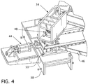
Figure 4 is an enlarged perspective view of a wall support saddle and associated hydraulic mechanisms of the upper support section shown inFigures 2 and3 ; -
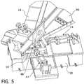
Figure 5 is another perspective view of the wall support saddle shown inFigure 4 ; -
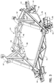
Figure 6 is a plan view of the upper support section shown inFigures 2 through 5 ; -
Figure 7A is a schematic view of the lower support of the embodiment described herein circumscribing a lower portion of the shell of a steam generator, shown in phantom, with the lower support in a retracted position; -
Figure 7B is a schematic view of the support shown inFigure 7A with the laterally extending arms deployed; -
Figure 7C is a perspective view ofFigure 7B with the steam generator slightly rotated to better show the extending member deployed; -
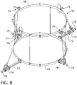
Figure 8 is an isometric view of the lower support shown inFigure 7 ; -
Figure 9 is a plan view of another embodiment of the upper support employing Hillman rollers to effect rotation of the steam generator; -
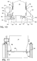
Figure 10 is a schematic side view of the embodiment illustrated inFigure 9 ; -
Figure 11 is a side view partially in section of another embodiment of the lower support described herein; and -
Figure 12 is an isometric view of an operator control station that can be employed with the embodiments illustrated inFigures 2-11 . - The lower portion of a nuclear steam generator that contains the primary side of the reactor coolant loop is typically shielded by a concrete cubicle in which the steam generator is supported. The embodiments described herein provide a temporary installation and alignment tool for supporting the steam generator within its concrete shielding in the course of construction of a nuclear power plant that enables the steam generator to be raised, lowered, rotated and tilted so it can be aligned with the connecting reactor coolant piping and the erection of a permanent steam generator support. While the support and alignment fixture described herein can be used as a permanent steam generator support, it serves more value as a temporary support during construction where it can be moved from generator to generator to facilitate the attachment of each of the steam generators to the reactor primary coolant system. The support fixture described herein uses structural steel support framing and hydraulic jacking and control monitoring devices to lift, jack, laterally move, tilt and rotate a steam generator during its installation process.
- Previous nuclear steam generators required stable base supports to be installed prior to setting the generators in position. The steam generators were fastened to the base supports and became self-supporting. Such a support is not practical for the type of steam generator illustrated in
Figure 1 , which has two main coolant pumps extending vertically from its lower end. - The embodiments described herein are unique in that they stabilize and support the entire weight of the steam generator after the steam generator is initially situated within its shielding compartment and maneuver the steam generator into alignment with the coolant piping to which it is to be welded. Thus, the embodiments set forth herein permit the overhead crane to be disengaged from the steam generator so that it is available for other construction work. Accordingly, the support fixtures described herein enable the setting of an unbalanced steam generator which has two reactor coolant pump casings welded on the bottom end of the steam generator, while supporting and enabling movement of the loaded steam generator in three directions and installation of permanent upper, lower and intermediate lateral supports and snubbers.
- While the alignment fixture of the embodiments described herein are illustrated as being applied to an AP1000 nuclear plant, and more particularly an AP1000 nuclear steam generator, it should be appreciated that the principles described herein can be applied to most any tube and shell steam generator design. One embodiment of the alignment and support fixture claimed hereafter is disclosed in
Figures 2-8 , with an upper support frame of the fixture illustrated inFigures 2-6 . In this embodiment, as illustrated inFigures 2A and 2B , theupper support frame 34 of thesupport fixture 32 is located on top of theconcrete walls 36 that surround the lower portion of thesteam generator 18. The lower portion of the steam generator can be temporarily or permanently supported within the compartment'swalls 36 in a variety of ways as illustrated, for example, inFigures 7 ,8 and11 , as will be described hereinafter. A second embodiment of theupper support 34 is illustrated inFigures 9 and10 . - As shown in
Figure 2 , theupper support frame 34 is formed from a structural steel frame that surrounds the generator and rests on four spacedshoes 38 that respectively rest on the top of theconcrete walls 36 that surround the lower portion of thesteam generator 18. As shown inFigures 2A and 2B , the steam generator bearing load is supported on two secondarymanway lift trunnions 40, by alift link 42 which extends vertically from diametrically opposite sides of thesupport frame 34. Eachsaddle 38 that supports theupper support frame 34 on theconcrete walls 36, engages at least one lateral hydraulic member, and preferably two suchhydraulic members 44 as shown inFigures 3-6 . Each lateralhydraulic member 44 is respectively attached or otherwise engaged withsupport ring 46 that encircles at least a portion of thesteam generator 18. Thesupport ring 46 may be a single component or comprise multiple members. Thesupport ring 46 supports or otherwise engages multiple verticalhydraulic members 48 which are each positioned between asaddle 38 and theupper support frame 34. In the embodiments shown inFigures 2-6 , thesupport ring 46 supports four verticalhydraulic members 48, one at each of the saddle locations approximately evenly spaced around thesupport ring 46 and is engaged respectively with two lateral hydraulic members respectively oriented in the X and Y planes. It can be appreciated best fromFigures 4 and5 , that the verticalhydraulic members 48 are respectively mounted on a lubronbearing translation pad 50 which is affixed to acorresponding wall saddle 38 and is in turn connected to each lateralhydraulic member 44. Another end of verticalhydraulic member 48 is connected to theupper support frame 34 and the radial inward portion of thelubron bearing 50 is connected to thesupport ring 46. The vertical hydraulic members engage and support theupper support frame 34 which in turn engages and supports the steamgenerator lift link 42. - The steam generator temporary support
upper support frame 42 thus described is supported by thecubicle walls 36 at an elevation of approximately 153 feet above the operating floor of the containment and has a relativelysmall operator platform 54 andcontrol box 52 for controlling the operation of the various hydraulic members. The vertical hydraulic members enable up and down movement of the steam generator up to approximately six inches (15.24 centimeters) in 1/32 inch (0.08 centimeters) increments. Similarly, the lateral hydraulic members enable lateral and transverse movement of the steam generator up to six inches (15.24 centimeters) in 1/32 inch (0.08 centimeters) increments. The system of this embodiment also enables correction of the steam generator vertical axis by 0.50 degrees. Control of the several hydraulic members can be had from thecontrol unit 52 which can be accessed on thecontrol platform 54 which is temporarily cantilevered from the top of theconcrete walls 36 that surround thegenerator 18. - As an alternate to the system illustrated in
Figures 2 through 6 , described above, the positioning and alignment system of this application may utilize a jacking mechanism such as the Enerpac® (or equivalent) single actinghydraulic jacks 56 which are connected to thesupport members 58 which carry the support links 42 which support thesteam generator trunnions 40. In the embodiment illustrated inFigures 9 and10 , Hillman Swivel OT rollers (or equivalent) 60 are employed with a synchronizedmaster control unit 52. Similarly, the GenMover "MUSE" moving system may be employed. InFigures 9 and10 , theHillman rollers 60 are supported from thesupport members 58 by the support links 62. The support and alignment system described herein may have asingle control unit 52 or be operated remotely by a technician. The control system is universal and may be interchangeable between multiple steam generators connected to the same reactor. The control system includes all of the hydraulic power units, hydraulic plumbing lines and control valves. Thehydraulic jacks 56 are preferably single acting with mechanical locking devices for safety. An Enerpac® PV-42 (or equivalent) control or monitoring device may be employed with such a system. - In operation, the embodiments illustrated in
Figures 2-6 may function as follows. An overhead crane or outside heavy duty mobile crane can transport and position a steam generator adjacent to the cubicle walls in which the generator is to be situated. The crane generally performs this function by engaging thetrunnions 40. The crane will lower the steam generator into the void area surrounded by thecubicle module walls 36 and over a vertical column support ("pogo stick"). As thesteam generator 18 is lowered by the crane, each trunnion respectively engages alift link 42 on theupper support frame 34. Upon the support frame engaging thesteam generator 18, via thelift link 42 and the lower restraint, for example, as illustrated inFigures 7 and8 , being secured, the hydraulic members connected to theupper support frame 34 may be utilized to maneuver the steam generator into the desired position in alignment with the primary coolant piping. In this regard, the verticalhydraulic members 48 may be activated to lower or raise thesteam generator 18. As previously mentioned, the verticalhydraulic members 48 support theupper support frame 34 and are attached to thesupport ring 46. The lateralhydraulic members 44 may then be activated to maneuver the steam generator in the X-Y direction. In the exemplary embodiment shown inFigures 2-6 , each lateralhydraulic member 44 is positioned adjacent and connected to asaddle 38 and each of the saddles are connected to thesupport ring 46 at circumferentially spaced locations. The lateralhydraulic member 44 can thus force thesupport ring 46 to change position. Forcing thesupport ring 46 to change position as a result of the activation of the lateralhydraulic member 44 causes the upper support frame to change position in an X-Y plane. In the embodiment shown, the support ring is engaged with thesteam generator 18 by way of toggles, and with thesaddle 38 by way of thelubron bearings 50. Any suitable device may be used for these connections. The toggles andlubron bearings 50 respectively cause the support ring to be movable attached to thesteam generator 18 and thesaddle 38. - Two exemplary, alternate lower restraint assemblies are shown in
Figures 7 ,8 and11 . Other similar restraints may also be used. In the embodiment shown inFigures 7 and8 , thelower restraint 64 comprises anupper band 66 and alower band 68. Both bands are respectively fixed to a lower section of thesteam generator 18 in an area where the primary coolant flows within U-tubes within the steam generator housing. Theupper band 66 and thelower band 68 are engaged with each other by a plurality of vertically connectingmembers 70. A plurality of spacedextension arms 72 withhydraulic jack systems 74 respectively at their distal ends extend radially from and are at spaced locations around thelower band 68. Theextension arms 72 are preferably pivotably connected to thelower band 68.Multiple winches 76 are respectively attached at various spaced locations on the circumference of theupper band 66 vertically aligned with theextension arm 72 for up righting thehydraulic jack system 74 at the distal end of theextension arm 72. Alignedextension arms 72 and winches 76 are respectively engaged with each other via a wire cable. Thewinches 76 are utilized to raise and lower theextension arms 72 to enable the extension arms to radially retract against the steam generator housing so that thesteam generator 18 can be lowered within theconcrete walls 36 of a shielding cubicle. Thewinches 76 can then lower theextension arm 72 so thehydraulic jack systems 74 can be extended to engage themodule walls 36 and brace the lower portion of thegenerator 18 against the cubicle module walls. Apad 78 is positioned at the end of eachextension 72. Thepad 78 engages themodule walls 36 during deployment of the lower restraint assembly.Figure 7A shows the lower restraint assembly with theextension arms 72 in the retracted position so that the generator can be lowered into its concrete walled cubicle that ultimately shields the generator.Figure 7B shows the winch cables fully extended and theextension arms 72 lowered for the deployment of thehydraulic jack 74 at their distal end.Figure 7C shows a similar view with theextension arms 72 fully extended with the generator slightly rotated from the view shown inFigures 7B and provides another perspective of anextended extension arm 72 and correspondingwinch 76. An alternatelower restraint 64 is shown inFigure 11 in which thesteam generator 18 is tied down to theconcrete walls 36 employing acable 80 and anchors 82. - An upper lateral support with a
snubber 84 may also be used to engage thesteam generator 18 to theconcrete walls 36 as shown inFigures 9 and10 . As previously mentioned with regard to the alternate embodiment of the upper support previously described with regard toFigures 9 and10 , thehydraulic jacks 56 may raise or lower the steam generator by raising or lowering thesupport members 58 and support links 62. Thehydraulic jack 56 may also remove any load from theHillman rollers 60 thereby allowing the Hillman rollers to be rotated to a different position. Lateral hydraulic actuators may also be used in this embodiment, as previously described with regard to the embodiment illustrated inFigures 2-6 , to force thesupport link 62 andsupport member 58 to move in various directions. The hydraulics are controlled by a computer system that synchronizes their actions to simultaneously cause the desired movement. The control system can also function to synchronize thehydraulic jacks 74 on thelower restraint 64 with theupper restraint 34. - While specific embodiments of the invention have been described in detail, it will be appreciated by those skilled in the art that various modifications and alternatives to those details could be developed in light of the overall teachings of the disclosure. For example, pneumatic cylinders may be employed in place of the hydraulic cylinders. Accordingly, the particular embodiments disclosed are meant to be illustrative only and not limiting as to the scope of the invention which is to be given the full breadth of the appended claims.
Claims (15)
- A nuclear steam generator support and alignment structure (32) for supporting a steam generator (18) in a vertical orientation, from a floor or an internal wall (36) of a nuclear containment and aligning an inlet nozzle and an outlet nozzle of the steam generator with a primary coolant loop piping (20) of a reactor system, comprising:a support fixture (34) configured to be supported on and extend from the floor or internal wall (36) of the nuclear containment and to be attached to at least two sides of the steam generator (18) to secure and support the entire weight of the steam generator in the vertical orientation, on the support fixture, the support fixture including:a base (38) configured to be supported on the floor or internal wall (36);a support section (42) configured to be attached to a portion of the circumference of a side of the steam generator (18), the support section forming a part of the support fixture; anda means (44, 48) connected between the base and the support section, the means being configured to raise, lower, laterally move and rotate the support section (42) relative to the base (38) with the steam generator (18) secured within the support section, the raising and lowering being in increments as little as 0.08cm, to align the steam generator inlet nozzle and outlet nozzle with the primary coolant loop piping (20) of the reactor system.
- The nuclear steam generator support and alignment structure (32) of Claim 1 wherein the means (44, 48) configured for raising, lowering, laterally moving and rotating the support section includes a plurality of hydraulic jacks between the base (38) and the support section (42).
- The nuclear steam generator support and alignment structure (32) of Claim 1 wherein the means (44, 48) configured for raising, lowering, laterally moving and rotating the support section (42) is also configured to tilt the support section (42) relative to the base (38) with the steam generator (18) secured within the support section.
- The nuclear steam generator support and alignment structure (32) of Claim 1 for use with a steam generator (18) that has a lower cylindrical reduced diameter section, an upper cylindrical section having a diameter larger than the reduced diameter section and a frustoconical section connecting the lower reduced diameter section to the enlarged diameter upper cylindrical section, wherein the support fixture comprises an upper support section (42) for connection to the upper cylindrical section and a lower support section (64) for connection to the lower cylindrical reduced diameter section.
- The nuclear steam generator support and alignment structure (32) of Claim 4 wherein the means (44, 48) configured to raise, lower, laterally move and rotate the support section (42) relative to the base (38) is connected between the upper support section (42) and the base (38).
- The nuclear steam generator support and alignment structure (32) of Claim 5 wherein the lower support section (64) is located below the base (38).
- The nuclear steam generator support and alignment structure (32) of Claim 4, wherein the upper support section (42) has four saddles (38) for supporting it at four points on an internal wall (36) at least partially surrounding the steam generator (18).
- The nuclear steam generator support and alignment structure (32) of Claim 7 wherein each saddle (38) has at least one lateral hydraulic member (44) associated with it for laterally moving the steam generator (18).
- The nuclear steam generator support and alignment structure (32) of Claim 8 wherein the upper support section (42) includes a support ring (46) configured substantially to surround the circumference of the upper cylindrical section of the steam generator (18), and each of the lateral hydraulic members (44) respectively engages the support ring to laterally move the support ring and thus the steam generator when the lateral hydraulic members are activated.
- The nuclear steam generator support and alignment structure (32) of Claim 9 wherein the support ring (46) is configured to support and engage a plurality of vertical hydraulic members (44, 48), wherein each of the vertical hydraulic members (48) is positioned adjacent a corresponding lateral hydraulic member (44).
- The nuclear steam generator support and alignment structure (32) of Claim 10 wherein each of the vertical hydraulic members (48) is configured to engage and support the support frame (34) which is engaged with a respective steam generator lift link (42).
- The nuclear steam generator support and alignment structure (32) of Claim 7 wherein the lower support section (64) is configured to be braced against at least two diametrically opposed points on an inside of the internal wall (36) in a manner that will permit the steam generator (18) to rotate and move up, down and laterally a given distance, but limit a side to side movement of the steam generator.
- The nuclear steam generator support and alignment structure (32) of Claim 1 wherein the means (44, 48) configured to raise, lower, laterally move and rotate the support section (42) relative to the base (38) comprises a plurality of hydraulic members (44, 48).
- The nuclear steam generator support and alignment structure (32) of Claim 13 wherein at least some of the hydraulic members (44) act in combination with a bearing plate (50) or roller support (60) to effect movement of the steam generator (18).
- The nuclear steam generator support and alignment structure (32) of Claim 13 wherein the hydraulic members (44, 48) are configured to tilt the support section (42) and the steam generator (18) when supported within the support section.
Applications Claiming Priority (3)
| Application Number | Priority Date | Filing Date | Title |
|---|---|---|---|
| US201161447892P | 2011-03-01 | 2011-03-01 | |
| US13/204,091 US20120224663A1 (en) | 2011-03-01 | 2011-08-05 | Nuclear steam generator support and alignment structure |
| PCT/US2012/022007 WO2012118570A1 (en) | 2011-03-01 | 2012-01-20 | Nuclear steam generator support and alignment structure |
Publications (3)
| Publication Number | Publication Date |
|---|---|
| EP2681500A1 EP2681500A1 (en) | 2014-01-08 |
| EP2681500A4 EP2681500A4 (en) | 2014-09-17 |
| EP2681500B1 true EP2681500B1 (en) | 2017-09-27 |
Family
ID=46753292
Family Applications (1)
| Application Number | Title | Priority Date | Filing Date |
|---|---|---|---|
| EP12752540.0A Not-in-force EP2681500B1 (en) | 2011-03-01 | 2012-01-20 | Nuclear steam generator support and alignment structure |
Country Status (7)
| Country | Link |
|---|---|
| US (1) | US20120224663A1 (en) |
| EP (1) | EP2681500B1 (en) |
| KR (1) | KR101835916B1 (en) |
| CN (1) | CN103492816B (en) |
| CA (1) | CA2830500A1 (en) |
| WO (1) | WO2012118570A1 (en) |
| ZA (1) | ZA201307121B (en) |
Cited By (1)
| Publication number | Priority date | Publication date | Assignee | Title |
|---|---|---|---|---|
| CN110504038A (en) * | 2018-05-16 | 2019-11-26 | 中国核工业第五建设有限公司 | A kind of support component of nuclear island steam generator |
Families Citing this family (18)
| Publication number | Priority date | Publication date | Assignee | Title |
|---|---|---|---|---|
| US9897234B2 (en) | 2013-12-26 | 2018-02-20 | Nuscale Power, Llc | Steam generator tube support |
| KR101613814B1 (en) * | 2015-01-29 | 2016-04-19 | 문인득 | Method for replacing the steam generator of pressurized water reactor of 2 loop type |
| CN104816111B (en) * | 2015-05-27 | 2016-05-11 | 上海电气核电设备有限公司 | The adjustment frock of nuclear boiler main pump pump case welding use |
| KR101702833B1 (en) * | 2015-10-30 | 2017-02-08 | 한국원자력연구원 | Apparatus and method for assuring centerline alignment of nuclear steam generator tube and supports |
| KR101675077B1 (en) * | 2015-12-07 | 2016-11-10 | 문인득 | Construction method and displacement system for constructing the reactor coolant piping and steam generator of pressurized water reactor of 2 loop type |
| KR101626270B1 (en) * | 2016-02-26 | 2016-05-31 | 문인득 | Apparatus for installing u-shaped module pipe on the closure loop of reactor coolant system |
| CN105913889A (en) * | 2016-07-05 | 2016-08-31 | 上海核工程研究设计院 | Three-loop nuclear energy system |
| CN105976877A (en) * | 2016-07-05 | 2016-09-28 | 上海核工程研究设计院 | Double-loop nuclear energy system |
| CN106782693B (en) * | 2016-12-29 | 2019-01-08 | 核动力运行研究所 | A kind of frame set mould assembly support equipment for steam generator |
| US12057240B2 (en) * | 2018-07-02 | 2024-08-06 | Invap S.E. | Compact reactor with horizontal steam generators and pressurizer |
| CN108986934B (en) * | 2018-08-01 | 2023-10-31 | 中广核研究院有限公司 | Single degree of freedom support device for heavy-duty containers |
| CN108953854B (en) * | 2018-08-01 | 2023-10-31 | 中广核研究院有限公司 | Reactor support device |
| USD922457S1 (en) * | 2019-11-28 | 2021-06-15 | NextLeaf Solutions Ltd. | Skid and frame set |
| USD923069S1 (en) * | 2020-01-09 | 2021-06-22 | NextLeaf Solutions Ltd. | Skid, frame, and vessel set |
| US12062461B2 (en) | 2021-02-04 | 2024-08-13 | Nuscale Power, Llc | Supports with integrated sensors for nuclear reactor steam generators, and associated systems and methods |
| CN115036052B (en) * | 2022-06-16 | 2024-11-12 | 中国核工业第五建设有限公司 | Nuclear power plant main container assembly device and method |
| CN115264479B (en) * | 2022-08-19 | 2025-08-01 | 中核能源科技有限公司 | Steam generator adjusting device |
| CN116110623B (en) * | 2022-12-16 | 2024-01-26 | 国科中子能(青岛)研究院有限公司 | Ultra-compact reactor system |
Citations (1)
| Publication number | Priority date | Publication date | Assignee | Title |
|---|---|---|---|---|
| US5257890A (en) * | 1992-01-21 | 1993-11-02 | Coleman Vickary | Tank inverter |
Family Cites Families (13)
| Publication number | Priority date | Publication date | Assignee | Title |
|---|---|---|---|---|
| US3027159A (en) * | 1958-10-24 | 1962-03-27 | Yates Plant Ltd | Roller apparatus for supporting and rotating cylindrical objects |
| DE2401610B2 (en) * | 1973-05-30 | 1976-08-12 | Kraftwerk Union AG, 4330 Mülheim | HEAT MOVABLE SUPPORT OF A STEAM GENERATOR FOR NUCLEAR REACTORS, IN PARTICULAR PRESSURE WATER REACTORS |
| FR2311388A1 (en) * | 1975-05-12 | 1976-12-10 | Commissariat Energie Atomique | SUPPORT DEVICE FOR A NUCLEAR BOILER |
| DE2706164A1 (en) * | 1977-02-14 | 1978-08-17 | Kraftwerk Union Ag | ASSEMBLY UNIT CONSISTING OF COOLANT PUMP AND STEAM GENERATOR, PREFERABLY FOR BURST-PROOF NUCLEAR REACTOR SYSTEMS |
| DE2808565A1 (en) * | 1978-02-28 | 1979-08-30 | Kraftwerk Union Ag | Top-suspended nuclear reactor pressure vessel - has lateral struts near bottom esp. for resisting earthquake forces |
| US4644908A (en) * | 1984-11-13 | 1987-02-24 | Westinghouse Electric Corp. | Steam generator wrapper closure and method of installing the same |
| FR2644568B1 (en) * | 1989-03-16 | 1991-07-05 | Intercontrole Sa | INTERVENTION DEVICE, PARTICULARLY FOR CHECKING, INSPECTING AND MAINTAINING HEAT EXCHANGERS |
| US5669594A (en) * | 1989-08-16 | 1997-09-23 | Minus K Technology, Inc. | Vibration isolating system |
| US5152958A (en) * | 1991-01-22 | 1992-10-06 | U.S. Tool & Die, Inc. | Spent nuclear fuel storage bridge |
| US5307386A (en) * | 1992-06-24 | 1994-04-26 | Westinghouse Electric Corp. | Apparatus and method for servicing an elongated suspended pump motor in an electric power plant with limited access |
| CN2181066Y (en) * | 1993-12-07 | 1994-10-26 | 上海核工程研究设计院 | Verticle support column structure for steam generator of pressurized-water nuclear power plant |
| US5752834A (en) * | 1995-11-27 | 1998-05-19 | Ling; Shou Hung | Motion/force simulators with six or three degrees of freedom |
| CN1312701C (en) * | 2005-01-07 | 2007-04-25 | 清华大学 | Damper-free support system for modular high temperature air-cooled pile pressure casing |
-
2011
- 2011-08-05 US US13/204,091 patent/US20120224663A1/en not_active Abandoned
-
2012
- 2012-01-20 WO PCT/US2012/022007 patent/WO2012118570A1/en not_active Ceased
- 2012-01-20 CN CN201280020214.4A patent/CN103492816B/en not_active Expired - Fee Related
- 2012-01-20 EP EP12752540.0A patent/EP2681500B1/en not_active Not-in-force
- 2012-01-20 KR KR1020137025510A patent/KR101835916B1/en not_active Expired - Fee Related
- 2012-01-20 CA CA2830500A patent/CA2830500A1/en not_active Abandoned
-
2013
- 2013-09-20 ZA ZA2013/07121A patent/ZA201307121B/en unknown
Patent Citations (1)
| Publication number | Priority date | Publication date | Assignee | Title |
|---|---|---|---|---|
| US5257890A (en) * | 1992-01-21 | 1993-11-02 | Coleman Vickary | Tank inverter |
Cited By (1)
| Publication number | Priority date | Publication date | Assignee | Title |
|---|---|---|---|---|
| CN110504038A (en) * | 2018-05-16 | 2019-11-26 | 中国核工业第五建设有限公司 | A kind of support component of nuclear island steam generator |
Also Published As
| Publication number | Publication date |
|---|---|
| KR20140014198A (en) | 2014-02-05 |
| KR101835916B1 (en) | 2018-03-07 |
| ZA201307121B (en) | 2014-05-28 |
| EP2681500A4 (en) | 2014-09-17 |
| CN103492816B (en) | 2016-05-04 |
| CA2830500A1 (en) | 2012-09-07 |
| CN103492816A (en) | 2014-01-01 |
| WO2012118570A1 (en) | 2012-09-07 |
| US20120224663A1 (en) | 2012-09-06 |
| EP2681500A1 (en) | 2014-01-08 |
Similar Documents
| Publication | Publication Date | Title |
|---|---|---|
| US20120224663A1 (en) | Nuclear steam generator support and alignment structure | |
| JP6288782B2 (en) | Method and apparatus for moving nuclear components under shielding | |
| US11935663B2 (en) | Control rod drive system for nuclear reactor | |
| WO2012027966A1 (en) | Method for assembling and installing steel containment vessel in nuclear power station | |
| KR101705476B1 (en) | Apparatus and method for installing reactor repairing device | |
| CN107345452A (en) | Nuclear power plant steel containment top cover assembly bracket | |
| JP3597570B2 (en) | Reactor dismantling method and apparatus | |
| JP2007183278A (en) | Device and method for carrying out work with respect to water chamber of heat exchanger | |
| EP3489968B1 (en) | Nuclear power generation system | |
| CN102146492A (en) | Method for installing converter body equipment and tooling platform | |
| NL2035480B1 (en) | Adjustable lifting and installation device | |
| CN104992737B (en) | Ultrasonic inspection apparatus of welds of CEPR nuclear power station control rod driving mechanism | |
| CA2907067C (en) | Upper vessel transport | |
| US20240344504A1 (en) | Methods for handling a load, in particular for installing or removing a blade on an offshore wind turbine, and devices for carrying out such methods | |
| US6266386B1 (en) | Lower reactor internals up-ending device | |
| CN113023095B (en) | Marine wind power installation tower section of thick bamboo fixing device of ship and tower section of thick bamboo transportation frock | |
| JP3100647B2 (en) | Maintenance device and method for an inverted canned motor pump | |
| CN102486943B (en) | Automatic shifting platform for welding inspection of adapter of pressure vessel | |
| CN104979028B (en) | CEPR nuclear power plant control rod driving mechanism weld ultrasonic scanner positioning device | |
| CN203134394U (en) | Pull bar device for upper horizontal support of steam generator at nuclear power station | |
| CN106816194B (en) | Installation method of passive advanced pressurized water reactor coolant pump | |
| JP5871472B2 (en) | Method for assembling tube group outer cylinder, steam generator assembling method, and tube group outer cylinder moving device | |
| JP2015169075A (en) | Transportable pump device | |
| JP7832941B2 (en) | Nuclear power plant system | |
| CN107186421A (en) | A kind of large-sized end enclosure base welding displacement device and its application method |
Legal Events
| Date | Code | Title | Description |
|---|---|---|---|
| PUAI | Public reference made under article 153(3) epc to a published international application that has entered the european phase |
Free format text: ORIGINAL CODE: 0009012 |
|
| 17P | Request for examination filed |
Effective date: 20131001 |
|
| AK | Designated contracting states |
Kind code of ref document: A1 Designated state(s): AL AT BE BG CH CY CZ DE DK EE ES FI FR GB GR HR HU IE IS IT LI LT LU LV MC MK MT NL NO PL PT RO RS SE SI SK SM TR |
|
| DAX | Request for extension of the european patent (deleted) | ||
| RIN1 | Information on inventor provided before grant (corrected) |
Inventor name: WALTERS, DANIEL, L. Inventor name: HERLEMAN, CHRISTOPHER, F. Inventor name: STEMLER, ABBY, L. Inventor name: EKEROTH, DOUGLAS, E. Inventor name: PATEL, RAMAN, G. Inventor name: ROHR, MATTHEW, M. Inventor name: OTT, HOWARD, L. Inventor name: FRANCIS, ARTHUR, W. |
|
| A4 | Supplementary search report drawn up and despatched |
Effective date: 20140820 |
|
| RIC1 | Information provided on ipc code assigned before grant |
Ipc: F24J 3/00 20060101AFI20140813BHEP |
|
| 17Q | First examination report despatched |
Effective date: 20151109 |
|
| REG | Reference to a national code |
Ref country code: DE Ref legal event code: R079 Ref document number: 602012037832 Country of ref document: DE Free format text: PREVIOUS MAIN CLASS: F24J0003000000 Ipc: F22B0037240000 |
|
| GRAP | Despatch of communication of intention to grant a patent |
Free format text: ORIGINAL CODE: EPIDOSNIGR1 |
|
| RIC1 | Information provided on ipc code assigned before grant |
Ipc: G21C 19/20 20060101ALI20170321BHEP Ipc: G21C 19/02 20060101ALI20170321BHEP Ipc: F22B 37/24 20060101AFI20170321BHEP |
|
| INTG | Intention to grant announced |
Effective date: 20170405 |
|
| GRAS | Grant fee paid |
Free format text: ORIGINAL CODE: EPIDOSNIGR3 |
|
| GRAA | (expected) grant |
Free format text: ORIGINAL CODE: 0009210 |
|
| AK | Designated contracting states |
Kind code of ref document: B1 Designated state(s): AL AT BE BG CH CY CZ DE DK EE ES FI FR GB GR HR HU IE IS IT LI LT LU LV MC MK MT NL NO PL PT RO RS SE SI SK SM TR |
|
| REG | Reference to a national code |
Ref country code: GB Ref legal event code: FG4D |
|
| REG | Reference to a national code |
Ref country code: CH Ref legal event code: EP |
|
| REG | Reference to a national code |
Ref country code: AT Ref legal event code: REF Ref document number: 932303 Country of ref document: AT Kind code of ref document: T Effective date: 20171015 |
|
| REG | Reference to a national code |
Ref country code: IE Ref legal event code: FG4D |
|
| REG | Reference to a national code |
Ref country code: DE Ref legal event code: R096 Ref document number: 602012037832 Country of ref document: DE |
|
| PG25 | Lapsed in a contracting state [announced via postgrant information from national office to epo] |
Ref country code: LT Free format text: LAPSE BECAUSE OF FAILURE TO SUBMIT A TRANSLATION OF THE DESCRIPTION OR TO PAY THE FEE WITHIN THE PRESCRIBED TIME-LIMIT Effective date: 20170927 Ref country code: SE Free format text: LAPSE BECAUSE OF FAILURE TO SUBMIT A TRANSLATION OF THE DESCRIPTION OR TO PAY THE FEE WITHIN THE PRESCRIBED TIME-LIMIT Effective date: 20170927 Ref country code: NO Free format text: LAPSE BECAUSE OF FAILURE TO SUBMIT A TRANSLATION OF THE DESCRIPTION OR TO PAY THE FEE WITHIN THE PRESCRIBED TIME-LIMIT Effective date: 20171227 Ref country code: FI Free format text: LAPSE BECAUSE OF FAILURE TO SUBMIT A TRANSLATION OF THE DESCRIPTION OR TO PAY THE FEE WITHIN THE PRESCRIBED TIME-LIMIT Effective date: 20170927 Ref country code: HR Free format text: LAPSE BECAUSE OF FAILURE TO SUBMIT A TRANSLATION OF THE DESCRIPTION OR TO PAY THE FEE WITHIN THE PRESCRIBED TIME-LIMIT Effective date: 20170927 |
|
| REG | Reference to a national code |
Ref country code: NL Ref legal event code: MP Effective date: 20170927 |
|
| REG | Reference to a national code |
Ref country code: LT Ref legal event code: MG4D |
|
| REG | Reference to a national code |
Ref country code: AT Ref legal event code: MK05 Ref document number: 932303 Country of ref document: AT Kind code of ref document: T Effective date: 20170927 |
|
| PG25 | Lapsed in a contracting state [announced via postgrant information from national office to epo] |
Ref country code: LV Free format text: LAPSE BECAUSE OF FAILURE TO SUBMIT A TRANSLATION OF THE DESCRIPTION OR TO PAY THE FEE WITHIN THE PRESCRIBED TIME-LIMIT Effective date: 20170927 Ref country code: RS Free format text: LAPSE BECAUSE OF FAILURE TO SUBMIT A TRANSLATION OF THE DESCRIPTION OR TO PAY THE FEE WITHIN THE PRESCRIBED TIME-LIMIT Effective date: 20170927 Ref country code: BG Free format text: LAPSE BECAUSE OF FAILURE TO SUBMIT A TRANSLATION OF THE DESCRIPTION OR TO PAY THE FEE WITHIN THE PRESCRIBED TIME-LIMIT Effective date: 20171227 Ref country code: GR Free format text: LAPSE BECAUSE OF FAILURE TO SUBMIT A TRANSLATION OF THE DESCRIPTION OR TO PAY THE FEE WITHIN THE PRESCRIBED TIME-LIMIT Effective date: 20171228 |
|
| PG25 | Lapsed in a contracting state [announced via postgrant information from national office to epo] |
Ref country code: NL Free format text: LAPSE BECAUSE OF FAILURE TO SUBMIT A TRANSLATION OF THE DESCRIPTION OR TO PAY THE FEE WITHIN THE PRESCRIBED TIME-LIMIT Effective date: 20170927 |
|
| REG | Reference to a national code |
Ref country code: FR Ref legal event code: PLFP Year of fee payment: 7 |
|
| PG25 | Lapsed in a contracting state [announced via postgrant information from national office to epo] |
Ref country code: RO Free format text: LAPSE BECAUSE OF FAILURE TO SUBMIT A TRANSLATION OF THE DESCRIPTION OR TO PAY THE FEE WITHIN THE PRESCRIBED TIME-LIMIT Effective date: 20170927 Ref country code: ES Free format text: LAPSE BECAUSE OF FAILURE TO SUBMIT A TRANSLATION OF THE DESCRIPTION OR TO PAY THE FEE WITHIN THE PRESCRIBED TIME-LIMIT Effective date: 20170927 |
|
| PG25 | Lapsed in a contracting state [announced via postgrant information from national office to epo] |
Ref country code: SM Free format text: LAPSE BECAUSE OF FAILURE TO SUBMIT A TRANSLATION OF THE DESCRIPTION OR TO PAY THE FEE WITHIN THE PRESCRIBED TIME-LIMIT Effective date: 20170927 Ref country code: AT Free format text: LAPSE BECAUSE OF FAILURE TO SUBMIT A TRANSLATION OF THE DESCRIPTION OR TO PAY THE FEE WITHIN THE PRESCRIBED TIME-LIMIT Effective date: 20170927 Ref country code: IS Free format text: LAPSE BECAUSE OF FAILURE TO SUBMIT A TRANSLATION OF THE DESCRIPTION OR TO PAY THE FEE WITHIN THE PRESCRIBED TIME-LIMIT Effective date: 20180127 Ref country code: SK Free format text: LAPSE BECAUSE OF FAILURE TO SUBMIT A TRANSLATION OF THE DESCRIPTION OR TO PAY THE FEE WITHIN THE PRESCRIBED TIME-LIMIT Effective date: 20170927 Ref country code: IT Free format text: LAPSE BECAUSE OF FAILURE TO SUBMIT A TRANSLATION OF THE DESCRIPTION OR TO PAY THE FEE WITHIN THE PRESCRIBED TIME-LIMIT Effective date: 20170927 Ref country code: EE Free format text: LAPSE BECAUSE OF FAILURE TO SUBMIT A TRANSLATION OF THE DESCRIPTION OR TO PAY THE FEE WITHIN THE PRESCRIBED TIME-LIMIT Effective date: 20170927 |
|
| REG | Reference to a national code |
Ref country code: DE Ref legal event code: R097 Ref document number: 602012037832 Country of ref document: DE |
|
| PG25 | Lapsed in a contracting state [announced via postgrant information from national office to epo] |
Ref country code: DK Free format text: LAPSE BECAUSE OF FAILURE TO SUBMIT A TRANSLATION OF THE DESCRIPTION OR TO PAY THE FEE WITHIN THE PRESCRIBED TIME-LIMIT Effective date: 20170927 |
|
| REG | Reference to a national code |
Ref country code: DE Ref legal event code: R119 Ref document number: 602012037832 Country of ref document: DE |
|
| PLBE | No opposition filed within time limit |
Free format text: ORIGINAL CODE: 0009261 |
|
| STAA | Information on the status of an ep patent application or granted ep patent |
Free format text: STATUS: NO OPPOSITION FILED WITHIN TIME LIMIT |
|
| PG25 | Lapsed in a contracting state [announced via postgrant information from national office to epo] |
Ref country code: PL Free format text: LAPSE BECAUSE OF FAILURE TO SUBMIT A TRANSLATION OF THE DESCRIPTION OR TO PAY THE FEE WITHIN THE PRESCRIBED TIME-LIMIT Effective date: 20170927 |
|
| REG | Reference to a national code |
Ref country code: CH Ref legal event code: PL |
|
| 26N | No opposition filed |
Effective date: 20180628 |
|
| PG25 | Lapsed in a contracting state [announced via postgrant information from national office to epo] |
Ref country code: DE Free format text: LAPSE BECAUSE OF NON-PAYMENT OF DUE FEES Effective date: 20180801 Ref country code: LU Free format text: LAPSE BECAUSE OF NON-PAYMENT OF DUE FEES Effective date: 20180120 |
|
| REG | Reference to a national code |
Ref country code: IE Ref legal event code: MM4A |
|
| REG | Reference to a national code |
Ref country code: BE Ref legal event code: MM Effective date: 20180131 |
|
| PG25 | Lapsed in a contracting state [announced via postgrant information from national office to epo] |
Ref country code: SI Free format text: LAPSE BECAUSE OF FAILURE TO SUBMIT A TRANSLATION OF THE DESCRIPTION OR TO PAY THE FEE WITHIN THE PRESCRIBED TIME-LIMIT Effective date: 20170927 Ref country code: LI Free format text: LAPSE BECAUSE OF NON-PAYMENT OF DUE FEES Effective date: 20180131 Ref country code: CH Free format text: LAPSE BECAUSE OF NON-PAYMENT OF DUE FEES Effective date: 20180131 Ref country code: BE Free format text: LAPSE BECAUSE OF NON-PAYMENT OF DUE FEES Effective date: 20180131 |
|
| PG25 | Lapsed in a contracting state [announced via postgrant information from national office to epo] |
Ref country code: IE Free format text: LAPSE BECAUSE OF NON-PAYMENT OF DUE FEES Effective date: 20180120 |
|
| PG25 | Lapsed in a contracting state [announced via postgrant information from national office to epo] |
Ref country code: MC Free format text: LAPSE BECAUSE OF FAILURE TO SUBMIT A TRANSLATION OF THE DESCRIPTION OR TO PAY THE FEE WITHIN THE PRESCRIBED TIME-LIMIT Effective date: 20170927 |
|
| PG25 | Lapsed in a contracting state [announced via postgrant information from national office to epo] |
Ref country code: MT Free format text: LAPSE BECAUSE OF NON-PAYMENT OF DUE FEES Effective date: 20180120 |
|
| PG25 | Lapsed in a contracting state [announced via postgrant information from national office to epo] |
Ref country code: HU Free format text: LAPSE BECAUSE OF FAILURE TO SUBMIT A TRANSLATION OF THE DESCRIPTION OR TO PAY THE FEE WITHIN THE PRESCRIBED TIME-LIMIT; INVALID AB INITIO Effective date: 20120120 Ref country code: PT Free format text: LAPSE BECAUSE OF FAILURE TO SUBMIT A TRANSLATION OF THE DESCRIPTION OR TO PAY THE FEE WITHIN THE PRESCRIBED TIME-LIMIT Effective date: 20170927 |
|
| PG25 | Lapsed in a contracting state [announced via postgrant information from national office to epo] |
Ref country code: CY Free format text: LAPSE BECAUSE OF FAILURE TO SUBMIT A TRANSLATION OF THE DESCRIPTION OR TO PAY THE FEE WITHIN THE PRESCRIBED TIME-LIMIT Effective date: 20170927 Ref country code: MK Free format text: LAPSE BECAUSE OF NON-PAYMENT OF DUE FEES Effective date: 20170927 |
|
| PG25 | Lapsed in a contracting state [announced via postgrant information from national office to epo] |
Ref country code: AL Free format text: LAPSE BECAUSE OF FAILURE TO SUBMIT A TRANSLATION OF THE DESCRIPTION OR TO PAY THE FEE WITHIN THE PRESCRIBED TIME-LIMIT Effective date: 20170927 |
|
| PGFP | Annual fee paid to national office [announced via postgrant information from national office to epo] |
Ref country code: FR Payment date: 20200427 Year of fee payment: 9 Ref country code: CZ Payment date: 20200616 Year of fee payment: 9 Ref country code: TR Payment date: 20200427 Year of fee payment: 9 |
|
| PGFP | Annual fee paid to national office [announced via postgrant information from national office to epo] |
Ref country code: GB Payment date: 20210128 Year of fee payment: 10 |
|
| PG25 | Lapsed in a contracting state [announced via postgrant information from national office to epo] |
Ref country code: FR Free format text: LAPSE BECAUSE OF NON-PAYMENT OF DUE FEES Effective date: 20210131 Ref country code: CZ Free format text: LAPSE BECAUSE OF NON-PAYMENT OF DUE FEES Effective date: 20210120 |
|
| GBPC | Gb: european patent ceased through non-payment of renewal fee |
Effective date: 20220120 |
|
| PG25 | Lapsed in a contracting state [announced via postgrant information from national office to epo] |
Ref country code: GB Free format text: LAPSE BECAUSE OF NON-PAYMENT OF DUE FEES Effective date: 20220120 |
|
| PG25 | Lapsed in a contracting state [announced via postgrant information from national office to epo] |
Ref country code: TR Free format text: LAPSE BECAUSE OF NON-PAYMENT OF DUE FEES Effective date: 20210120 |