EP2681399B1 - Methods of forming polycrystalline elements - Google Patents
Methods of forming polycrystalline elements Download PDFInfo
- Publication number
- EP2681399B1 EP2681399B1 EP12754871.7A EP12754871A EP2681399B1 EP 2681399 B1 EP2681399 B1 EP 2681399B1 EP 12754871 A EP12754871 A EP 12754871A EP 2681399 B1 EP2681399 B1 EP 2681399B1
- Authority
- EP
- European Patent Office
- Prior art keywords
- substrate
- polycrystalline table
- another
- polycrystalline
- attaching
- Prior art date
- Legal status (The legal status is an assumption and is not a legal conclusion. Google has not performed a legal analysis and makes no representation as to the accuracy of the status listed.)
- Active
Links
Images




Classifications
-
- E—FIXED CONSTRUCTIONS
- E21—EARTH OR ROCK DRILLING; MINING
- E21B—EARTH OR ROCK DRILLING; OBTAINING OIL, GAS, WATER, SOLUBLE OR MELTABLE MATERIALS OR A SLURRY OF MINERALS FROM WELLS
- E21B10/00—Drill bits
- E21B10/46—Drill bits characterised by wear resisting parts, e.g. diamond inserts
- E21B10/56—Button-type inserts
- E21B10/567—Button-type inserts with preformed cutting elements mounted on a distinct support, e.g. polycrystalline inserts
- E21B10/573—Button-type inserts with preformed cutting elements mounted on a distinct support, e.g. polycrystalline inserts characterised by support details, e.g. the substrate construction or the interface between the substrate and the cutting element
- E21B10/5735—Interface between the substrate and the cutting element
-
- E—FIXED CONSTRUCTIONS
- E21—EARTH OR ROCK DRILLING; MINING
- E21B—EARTH OR ROCK DRILLING; OBTAINING OIL, GAS, WATER, SOLUBLE OR MELTABLE MATERIALS OR A SLURRY OF MINERALS FROM WELLS
- E21B10/00—Drill bits
- E21B10/08—Roller bits
- E21B10/22—Roller bits characterised by bearing, lubrication or sealing details
-
- B—PERFORMING OPERATIONS; TRANSPORTING
- B24—GRINDING; POLISHING
- B24D—TOOLS FOR GRINDING, BUFFING OR SHARPENING
- B24D18/00—Manufacture of grinding tools or other grinding devices, e.g. wheels, not otherwise provided for
- B24D18/0009—Manufacture of grinding tools or other grinding devices, e.g. wheels, not otherwise provided for using moulds or presses
-
- B—PERFORMING OPERATIONS; TRANSPORTING
- B24—GRINDING; POLISHING
- B24D—TOOLS FOR GRINDING, BUFFING OR SHARPENING
- B24D3/00—Physical features of abrasive bodies, or sheets, e.g. abrasive surfaces of special nature; Abrasive bodies or sheets characterised by their constituents
- B24D3/02—Physical features of abrasive bodies, or sheets, e.g. abrasive surfaces of special nature; Abrasive bodies or sheets characterised by their constituents the constituent being used as bonding agent
- B24D3/04—Physical features of abrasive bodies, or sheets, e.g. abrasive surfaces of special nature; Abrasive bodies or sheets characterised by their constituents the constituent being used as bonding agent and being essentially inorganic
- B24D3/06—Physical features of abrasive bodies, or sheets, e.g. abrasive surfaces of special nature; Abrasive bodies or sheets characterised by their constituents the constituent being used as bonding agent and being essentially inorganic metallic or mixture of metals with ceramic materials, e.g. hard metals, "cermets", cements
-
- B—PERFORMING OPERATIONS; TRANSPORTING
- B24—GRINDING; POLISHING
- B24D—TOOLS FOR GRINDING, BUFFING OR SHARPENING
- B24D99/00—Subject matter not provided for in other groups of this subclass
- B24D99/005—Segments of abrasive wheels
-
- C—CHEMISTRY; METALLURGY
- C22—METALLURGY; FERROUS OR NON-FERROUS ALLOYS; TREATMENT OF ALLOYS OR NON-FERROUS METALS
- C22C—ALLOYS
- C22C26/00—Alloys containing diamond or cubic or wurtzitic boron nitride, fullerenes or carbon nanotubes
-
- C—CHEMISTRY; METALLURGY
- C22—METALLURGY; FERROUS OR NON-FERROUS ALLOYS; TREATMENT OF ALLOYS OR NON-FERROUS METALS
- C22C—ALLOYS
- C22C29/00—Alloys based on carbides, oxides, nitrides, borides, or silicides, e.g. cermets, or other metal compounds, e.g. oxynitrides, sulfides
- C22C29/02—Alloys based on carbides, oxides, nitrides, borides, or silicides, e.g. cermets, or other metal compounds, e.g. oxynitrides, sulfides based on carbides or carbonitrides
- C22C29/06—Alloys based on carbides, oxides, nitrides, borides, or silicides, e.g. cermets, or other metal compounds, e.g. oxynitrides, sulfides based on carbides or carbonitrides based on carbides, but not containing other metal compounds
-
- C—CHEMISTRY; METALLURGY
- C22—METALLURGY; FERROUS OR NON-FERROUS ALLOYS; TREATMENT OF ALLOYS OR NON-FERROUS METALS
- C22C—ALLOYS
- C22C29/00—Alloys based on carbides, oxides, nitrides, borides, or silicides, e.g. cermets, or other metal compounds, e.g. oxynitrides, sulfides
- C22C29/14—Alloys based on carbides, oxides, nitrides, borides, or silicides, e.g. cermets, or other metal compounds, e.g. oxynitrides, sulfides based on borides
-
- E—FIXED CONSTRUCTIONS
- E21—EARTH OR ROCK DRILLING; MINING
- E21B—EARTH OR ROCK DRILLING; OBTAINING OIL, GAS, WATER, SOLUBLE OR MELTABLE MATERIALS OR A SLURRY OF MINERALS FROM WELLS
- E21B10/00—Drill bits
- E21B10/46—Drill bits characterised by wear resisting parts, e.g. diamond inserts
- E21B10/56—Button-type inserts
- E21B10/567—Button-type inserts with preformed cutting elements mounted on a distinct support, e.g. polycrystalline inserts
- E21B10/573—Button-type inserts with preformed cutting elements mounted on a distinct support, e.g. polycrystalline inserts characterised by support details, e.g. the substrate construction or the interface between the substrate and the cutting element
-
- F—MECHANICAL ENGINEERING; LIGHTING; HEATING; WEAPONS; BLASTING
- F16—ENGINEERING ELEMENTS AND UNITS; GENERAL MEASURES FOR PRODUCING AND MAINTAINING EFFECTIVE FUNCTIONING OF MACHINES OR INSTALLATIONS; THERMAL INSULATION IN GENERAL
- F16C—SHAFTS; FLEXIBLE SHAFTS; ELEMENTS OR CRANKSHAFT MECHANISMS; ROTARY BODIES OTHER THAN GEARING ELEMENTS; BEARINGS
- F16C17/00—Sliding-contact bearings for exclusively rotary movement
-
- F—MECHANICAL ENGINEERING; LIGHTING; HEATING; WEAPONS; BLASTING
- F16—ENGINEERING ELEMENTS AND UNITS; GENERAL MEASURES FOR PRODUCING AND MAINTAINING EFFECTIVE FUNCTIONING OF MACHINES OR INSTALLATIONS; THERMAL INSULATION IN GENERAL
- F16C—SHAFTS; FLEXIBLE SHAFTS; ELEMENTS OR CRANKSHAFT MECHANISMS; ROTARY BODIES OTHER THAN GEARING ELEMENTS; BEARINGS
- F16C17/00—Sliding-contact bearings for exclusively rotary movement
- F16C17/12—Sliding-contact bearings for exclusively rotary movement characterised by features not related to the direction of the load
-
- F—MECHANICAL ENGINEERING; LIGHTING; HEATING; WEAPONS; BLASTING
- F16—ENGINEERING ELEMENTS AND UNITS; GENERAL MEASURES FOR PRODUCING AND MAINTAINING EFFECTIVE FUNCTIONING OF MACHINES OR INSTALLATIONS; THERMAL INSULATION IN GENERAL
- F16C—SHAFTS; FLEXIBLE SHAFTS; ELEMENTS OR CRANKSHAFT MECHANISMS; ROTARY BODIES OTHER THAN GEARING ELEMENTS; BEARINGS
- F16C33/00—Parts of bearings; Special methods for making bearings or parts thereof
- F16C33/02—Parts of sliding-contact bearings
- F16C33/04—Brasses; Bushes; Linings
- F16C33/043—Sliding surface consisting mainly of ceramics, cermets or hard carbon, e.g. diamond like carbon [DLC]
-
- F—MECHANICAL ENGINEERING; LIGHTING; HEATING; WEAPONS; BLASTING
- F16—ENGINEERING ELEMENTS AND UNITS; GENERAL MEASURES FOR PRODUCING AND MAINTAINING EFFECTIVE FUNCTIONING OF MACHINES OR INSTALLATIONS; THERMAL INSULATION IN GENERAL
- F16C—SHAFTS; FLEXIBLE SHAFTS; ELEMENTS OR CRANKSHAFT MECHANISMS; ROTARY BODIES OTHER THAN GEARING ELEMENTS; BEARINGS
- F16C33/00—Parts of bearings; Special methods for making bearings or parts thereof
- F16C33/02—Parts of sliding-contact bearings
- F16C33/04—Brasses; Bushes; Linings
- F16C33/06—Sliding surface mainly made of metal
- F16C33/12—Structural composition; Use of special materials or surface treatments, e.g. for rust-proofing
- F16C33/121—Use of special materials
-
- F—MECHANICAL ENGINEERING; LIGHTING; HEATING; WEAPONS; BLASTING
- F16—ENGINEERING ELEMENTS AND UNITS; GENERAL MEASURES FOR PRODUCING AND MAINTAINING EFFECTIVE FUNCTIONING OF MACHINES OR INSTALLATIONS; THERMAL INSULATION IN GENERAL
- F16C—SHAFTS; FLEXIBLE SHAFTS; ELEMENTS OR CRANKSHAFT MECHANISMS; ROTARY BODIES OTHER THAN GEARING ELEMENTS; BEARINGS
- F16C33/00—Parts of bearings; Special methods for making bearings or parts thereof
- F16C33/02—Parts of sliding-contact bearings
- F16C33/04—Brasses; Bushes; Linings
- F16C33/26—Brasses; Bushes; Linings made from wire coils; made from a number of discs, rings, rods, or other members
-
- B—PERFORMING OPERATIONS; TRANSPORTING
- B22—CASTING; POWDER METALLURGY
- B22F—WORKING METALLIC POWDER; MANUFACTURE OF ARTICLES FROM METALLIC POWDER; MAKING METALLIC POWDER; APPARATUS OR DEVICES SPECIALLY ADAPTED FOR METALLIC POWDER
- B22F2999/00—Aspects linked to processes or compositions used in powder metallurgy
-
- C—CHEMISTRY; METALLURGY
- C22—METALLURGY; FERROUS OR NON-FERROUS ALLOYS; TREATMENT OF ALLOYS OR NON-FERROUS METALS
- C22C—ALLOYS
- C22C2204/00—End product comprising different layers, coatings or parts of cermet
-
- F—MECHANICAL ENGINEERING; LIGHTING; HEATING; WEAPONS; BLASTING
- F16—ENGINEERING ELEMENTS AND UNITS; GENERAL MEASURES FOR PRODUCING AND MAINTAINING EFFECTIVE FUNCTIONING OF MACHINES OR INSTALLATIONS; THERMAL INSULATION IN GENERAL
- F16C—SHAFTS; FLEXIBLE SHAFTS; ELEMENTS OR CRANKSHAFT MECHANISMS; ROTARY BODIES OTHER THAN GEARING ELEMENTS; BEARINGS
- F16C17/00—Sliding-contact bearings for exclusively rotary movement
- F16C17/02—Sliding-contact bearings for exclusively rotary movement for radial load only
-
- F—MECHANICAL ENGINEERING; LIGHTING; HEATING; WEAPONS; BLASTING
- F16—ENGINEERING ELEMENTS AND UNITS; GENERAL MEASURES FOR PRODUCING AND MAINTAINING EFFECTIVE FUNCTIONING OF MACHINES OR INSTALLATIONS; THERMAL INSULATION IN GENERAL
- F16C—SHAFTS; FLEXIBLE SHAFTS; ELEMENTS OR CRANKSHAFT MECHANISMS; ROTARY BODIES OTHER THAN GEARING ELEMENTS; BEARINGS
- F16C17/00—Sliding-contact bearings for exclusively rotary movement
- F16C17/04—Sliding-contact bearings for exclusively rotary movement for axial load only
-
- F—MECHANICAL ENGINEERING; LIGHTING; HEATING; WEAPONS; BLASTING
- F16—ENGINEERING ELEMENTS AND UNITS; GENERAL MEASURES FOR PRODUCING AND MAINTAINING EFFECTIVE FUNCTIONING OF MACHINES OR INSTALLATIONS; THERMAL INSULATION IN GENERAL
- F16C—SHAFTS; FLEXIBLE SHAFTS; ELEMENTS OR CRANKSHAFT MECHANISMS; ROTARY BODIES OTHER THAN GEARING ELEMENTS; BEARINGS
- F16C2352/00—Apparatus for drilling
-
- Y—GENERAL TAGGING OF NEW TECHNOLOGICAL DEVELOPMENTS; GENERAL TAGGING OF CROSS-SECTIONAL TECHNOLOGIES SPANNING OVER SEVERAL SECTIONS OF THE IPC; TECHNICAL SUBJECTS COVERED BY FORMER USPC CROSS-REFERENCE ART COLLECTIONS [XRACs] AND DIGESTS
- Y10—TECHNICAL SUBJECTS COVERED BY FORMER USPC
- Y10T—TECHNICAL SUBJECTS COVERED BY FORMER US CLASSIFICATION
- Y10T428/00—Stock material or miscellaneous articles
- Y10T428/24—Structurally defined web or sheet [e.g., overall dimension, etc.]
- Y10T428/24479—Structurally defined web or sheet [e.g., overall dimension, etc.] including variation in thickness
- Y10T428/24521—Structurally defined web or sheet [e.g., overall dimension, etc.] including variation in thickness with component conforming to contour of nonplanar surface
Definitions
- Embodiments of the present invention relate generally to bearings and cutting elements for earth-boring tools and to methods of forming such bearings and cutting elements. Specifically, embodiments of the disclosure relate to methods of attaching a polycrystalline table to a substrate and bearings and cutting elements formed by such methods.
- Earth-boring tools for forming wellbores in subterranean earth formations may include a plurality of cutting elements secured to a body.
- fixed-cutter earth-boring rotary drill bits also referred to as "drag bits”
- drag bits include a plurality of cutting elements that are fixedly attached to a bit body of the drill bit.
- roller cone earth-boring rotary drill bits may include cones that are mounted on bearing pins extending from legs of a bit body such that each cone is capable of rotating about the bearing pin on which it is mounted.
- a plurality of cutting elements may be mounted to each cone of the drill bit.
- the cutting elements used in such earth-boring tools often include polycrystalline diamond compact (often referred to as "PDC”) cutting elements, also termed “cutters,” which are cutting elements that include a polycrystalline diamond (PCD) material, which may be characterized as a superabrasive or superhard material.
- PCD polycrystalline diamond
- Such polycrystalline diamond materials are formed by sintering and bonding together relatively small synthetic, natural, or a combination of synthetic and natural diamond grains or crystals, termed “grit,” under conditions of high temperature and high pressure in the presence of a catalyst, such as, for example, cobalt, iron, nickel, or alloys and mixtures thereof, to form a layer of polycrystalline diamond material, also called a diamond table.
- a catalyst such as, for example, cobalt, iron, nickel, or alloys and mixtures thereof
- the cutting element substrate may comprise a cermet material, i.e., a ceramic-metal composite material, such as, for example, cobalt-cemented tungsten carbide.
- the polycrystalline diamond table may be formed on the cutting element, for example, during the HTHP sintering process.
- cobalt or other catalyst material in the cutting element substrate may be swept into the diamond grains or crystals during sintering and serve as a catalyst material for forming a diamond table from the diamond grains or crystals.
- Powdered catalyst material may also be mixed with the diamond grains or crystals prior to sintering the grains or crystals together in an HTHP process.
- the diamond table may be formed separately from the cutting element substrate and subsequently attached thereto.
- the present invention provides a method of forming a polycrystalline element in accordance with claim 1.
- earth-boring drill bits such as earth-boring rotary drill bits, sometimes referred to as "roller cone” or “rolling cone” bits
- diamond-bearing structures in accordance with the disclosure may be employed in any earth-boring tool employing a structure comprising a polycrystalline superabrasive material attached to a supporting substrate.
- earth-boring tool and “earth-boring drill bit,” as used herein, mean and include any type of bit or tool used for drilling during the formation or enlargement of a wellbore in a subterranean formation and include, for example, fixed-cutter bits, percussion bits, core bits, eccentric bits, bicenter bits, reamers, mills, drag bits, hybrid bits, and other drilling bits and tools known in the art.
- polycrystalline table means and includes any structure comprising a plurality of grains (i.e., crystals) of superabrasive, also known in the art as superhard, material that are bonded directly together by inter-granular bonds.
- the crystal structures of the individual grains of the material may be randomly oriented in space within the polycrystalline material.
- inter-granular bond means and includes any direct atomic bond (e.g., covalent, metallic, etc. ) between atoms in adjacent grains of superabrasive material.
- FIG. 1 a cross-sectional view of a roller cone 102 of an earth-boring rotary drill bit 100, commonly termed a "rock" bit, is shown.
- the earth-boring rotary drill bit 100 includes a bit body (not shown) having legs 104 depending from the body.
- a roller cone 106 is rotatably mounted to a bearing pin 108 on each of the legs 104.
- Each roller cone 106 may comprise a plurality of cutting elements, such as inserts 110 disposed in recesses formed in the roller cone 106 and attached to the roller cone 106.
- Each insert 110 may comprise a polycrystalline table 112 attached to a portion 114 ( e.g., a layer) of a first substrate.
- the portion 114 of the first substrate may be attached to another substrate 116.
- the drill bit 100 also comprises a bearing system.
- the bearing system includes a radial bearing assembly 118 and an axial bearing assembly 120.
- the radial bearing assembly 118 and the axial bearing assembly 120 may comprise abutting polycrystalline tables 112 attached to portions 114 of first substrates. Each portion 114 of a first substrate may be attached to another substrate 116.
- the abutting polycrystalline tables 112 may be configured to rotate slidably against one another.
- the roller cone 102 may rotate about the bearing pin 108 and roll around a bottom of a wellbore.
- the polycrystalline tables 112 of inserts 110 may impact and crush an underlying earth formation.
- the radial bearing assembly 118 may bear radial forces acting on the roller cone 102 as its abutting polycrystalline tables 112 slide against one another.
- the axial bearing assembly 120 may bear axial forces acting on the roller cone 102 as its abutting polycrystalline tables 112 slide against one another.
- the cutting element 110' comprises a polycrystalline table 112 attached to a portion 114 of a first substrate, another portion opposite that to which polycrystalline table 112 is attached having been removed. Portion 114 may also be characterized as a residual substrate. The portion 114 of the first substrate is attached, in turn, to another substrate 116. Thus, the portion 114 of the first substrate is interposed between the polycrystalline table 112 and the other substrate 116.
- the cutting element 110' may be substantially cylindrical, the substrate 116 comprising a cylinder, the polycrystalline table 112 comprising a disc, and the portion 114 of the first substrate comprising a disc.
- a chamfer or beveled edge may be disposed between a side surface and a cutting face of the polycrystalline table 112.
- the cutting element 110' may comprise a cutting element 110' conventionally attached to and deployed with a fixed-cutter earth-boring drill bit, which is also commonly termed a "drag" bit.
- the insert 110 comprises a polycrystalline table 112 attached to a portion 114 of a first substrate.
- the portion 114 of the first substrate is attached, in turn, to another substrate 116.
- the portion 114 of the first substrate is interposed between the polycrystalline table 112 and the other substrate 116.
- the substrate 116 comprises a cylinder and the portion 114 of the first substrate comprises a disc disposed on the substrate.
- the polycrystalline table 112 comprises a hemisphere.
- the insert 110 may comprise a dome-shaped cutting surface.
- the polycrystalline table 112 may comprise, for example, a chisel shape, a tombstone shape, or other cutting shapes and surfaces known in the art.
- the insert 110 may be of a type typically attached to and deployed with a roller cone 102 of an earth-boring rotary drill bit 100 (see FIG. 1 ).
- the axial bearing assembly 120 may be configured to accommodate axial forces acting on the axial bearing assembly 120 during relative movement of the components thereof.
- the axial bearing assembly 120 comprises two opposing polycrystalline tables 112.
- the polycrystalline tables 112 may comprise discs. When in use, opposing flat, circular surfaces of the polycrystalline tables 112 may abut against one another. The opposing flat, circular surfaces of the polycrystalline tables 112 may slide against one another as at least one of the polycrystalline tables 112 rotates about its central longitudinal axis.
- each polycrystalline table 112 is attached to a portion 114 of a first substrate. The portion 114 of the first substrate is attached, in turn, to another substrate 116.
- the portion 114 of the first substrate is interposed between the polycrystalline table 112 and the other substrate 116.
- the portion 114 of the first substrate may comprise a disc, and the other substrate 116 may comprise a cylinder.
- the axial bearing assembly 120 may comprise two opposing cylinders.
- a radial bearing assembly 118 may be configured to accommodate radial forces acting on the radial bearing assembly 118 during relative movement of the components thereof.
- the radial bearing assembly 118 comprises a plurality of opposing polycrystalline tables 112.
- the polycrystalline tables 112 may comprise bearing pads. When in use, a radially outer surface of one polycrystalline table 112 may abut against a radially inner surface of the other polycrystalline table 112, the one polycrystalline table 112 being concentrically nested within the other polycrystalline table 112.
- the opposing surfaces of the polycrystalline tables 112 may slide against one another as at least some of the polycrystalline tables 112 rotate about a central axis of the radial bearing assembly 118.
- Each polycrystalline table 112 is attached to a portion 114 of a first substrate.
- the portion 114 of the first substrate is attached, in turn, to another substrate 116.
- the portion 114 of the first substrate is interposed between the polycrystalline table 112 and the other substrate 116.
- Each of the portions 114 of the first substrate and the other substrate 116 may comprise annular members disposed radially adjacent to one another.
- the portion 114 of the first substrate and the other substrate 116 may comprise, therefore, concentric rings having polycrystalline tables attached to the portions 114 of the first substrates thereof.
- the radial bearing assembly 118 may comprise two concentrically nested annular members.
- the polycrystalline table 112 of any of the embodiments shown in FIGS. 2 through 5 comprise a superabrasive, sometimes referred to as superhard, material.
- the polycrystalline table 112 may comprise synthetic diamond, natural diamond, a combination of synthetic diamond and natural diamond, cubic boron nitride, or other superabrasive materials known in the art.
- the polycrystalline table 112 may comprise a plurality of interbonded grains of superabrasive material of at least substantially uniform size.
- the polycrystalline table 112 may comprise a plurality of interbonded grains of superabrasive material of non-uniform size.
- interbonded grains of superabrasive material of different sizes may be interspersed throughout the polycrystalline table in a substantially uniform fashion.
- interbonded grains of superabrasive material may be disposed in layers, each layer having a different average grain size, to form a layered polycrystalline table.
- interbonded grains of superabrasive material may be graded, the average grain size gradually increasing or decreasing in a direction through the polycrystalline table 112.
- the portion 114 of the first substrate and the other substrate 116 may comprise a hard material.
- the hard material may comprise, for example, a ceramic-metal composite material (i.e., a "cermet" material) comprising a plurality of hard ceramic particles dispersed throughout a metal matrix material.
- the hard ceramic particles may comprise carbides, nitrides, oxides, and borides (including boron carbide (B 4 C)). More specifically, the hard ceramic particles may comprise carbides and borides made from elements such as W, Ti, Mo, Nb, V, Hf, Ta, Cr, Zr, Al, and Si.
- materials that may be used to form hard ceramic particles include tungsten carbide (WC, W 2 C, and combinations of WC and W 2 C), titanium carbide (TiC), tantalum carbide (TaC), titanium diboride (TiB 2 ), chromium carbides, titanium nitride (TiN), aluminium oxide (Al 2 O 3 ), aluminium nitride (AlN), and silicon carbide (SiC).
- the metal matrix material of the ceramic-metal composite material may include, for example, cobalt-based, iron-based, nickel-based, iron- and nickel-based, cobalt- and nickel-based, and iron- and cobalt-based alloys.
- the matrix material may also be selected from commercially pure elements such as, for example, cobalt, iron, and nickel.
- the hard material may comprise a plurality of tungsten carbide particles in a cobalt matrix.
- the portion 114 of the first substrate and the other substrate 116 may comprise hard particles of at least substantially uniform size.
- the portion 114 of the first substrate and the other substrate 116 may comprise hard particles having a multi-modal size distribution.
- an average particle size of hard particles of the portion 114 of the first substrate may be substantially equal to an average particle size of hard particles of the other substrate 116.
- the average particle size of hard particles of the portion 114 of the first substrate may substantially differ from the average particle size of hard particles of the other substrate 116.
- the average particle size of hard particles of the portion 114 of the first substrate may be substantially greater than, such as, for example, at least two times greater than, the average particle size of hard particles of the other substrate 116.
- the insert 110 comprises a polycrystalline table 112 attached to a portion 114 of a first substrate.
- the polycrystalline table 112 comprises a hollow dome shape, and the portion 114 of the first substrate comprises a dome-shaped protrusion abutting the polycrystalline table 112.
- the portion 114 of the first substrate may comprise an intermediate layer 115 adjacent the polycrystalline table 112.
- the intermediate layer 115 may comprise a mixture of particles comprising a superabrasive material and particles comprising a hard material, as described previously herein.
- the intermediate layer 115 may comprise a graded layer of the portion 114 of the first substrate to transition from the material of the polycrystalline table 112 to the material of a remainder of the portion 114 of the first substrate. In other embodiments, multiple intermediate layers 115 may be provided with the portion 114 of the first substrate.
- the portion 114 of the first substrate is attached to another substrate 116. Thus, the portion 114 of the first substrate is interposed between the polycrystalline table 112 and the other substrate 116.
- the insert 110 comprises a polycrystalline table 112 attached to a portion 114 of a first substrate.
- the polycrystalline table 112 comprises a solid dome shape, such as, for example, a hemisphere.
- the polycrystalline table 112 may be attached to a substantially disc-shaped portion 114 of a first substrate.
- the portion 114 of the first substrate is attached, in turn, to another substrate 116.
- the portion 114 of the first substrate is interposed between the polycrystalline table 112 and the other substrate 116.
- the cutting element 110' comprises a polycrystalline table 112 attached to a portion 114 of a first substrate.
- the polycrystalline table 112 comprises a cylinder or disc shape.
- the portion 114 of the first substrate likewise comprises a cylinder or disc shape.
- An interface 117 between the polycrystalline table 112 and the portion 114 of the first substrate may be planar or substantially planar.
- the portion 114 of the first substrate is attached to another substrate 116. Thus, the portion 114 of the first substrate is interposed between the polycrystalline table 112 and the other substrate 116.
- the cutting element 110' comprises a polycrystalline table attached to a portion 114 of a first substrate.
- the polycrystalline table 112 comprises a substantially cylinder or substantially disc-like shape.
- the portion 114 of the first substrate comprises a substantially cylinder or substantially disc-like shape.
- An interface 117 between the polycrystalline table 112 and the portion 114 of the first substrate may comprise a non-planar interface design, such as, for example, alternating protrusions and recesses, an annulus, radially extending spokes, or other non-planar interface designs known in the art.
- the portion 114 of the first substrate is attached to another substrate 116.
- the portion 114 of the first substrate is interposed between the polycrystalline table 112 and the other substrate 116.
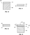
- FIGS. 10 through 13 a method of attaching a polycrystalline table to a substrate according to the present invention is shown.
- an intermediate structure 122 in the process of forming a cutting element or other structure comprising a polycrystalline table attached to a substrate.
- the intermediate structure 122 comprises a polycrystalline table 112 attached to a first substrate 124.
- the intermediate structure 122 may be formed, for example, by disposing a mass of hard material, a plurality of particles comprising a superabrasive material, and a catalyst material into a mold.
- the hard material may comprise, for example, any of the hard materials described previously.
- the hard material may comprise a plurality of tungsten carbide particles in a cobalt matrix, known in the art as cobalt-cemented tungsten carbide.
- the hard material may be present in the form of a fully sintered (i.e., having a final density) part.
- the superabrasive material may comprise, for example, any of the superabrasive materials described previously.
- the catalyst material may comprise, for example, an alloy (e.g ., cobalt-based, iron-based, nickel-based, iron and nickel-based, cobalt and nickel-based, and iron and cobalt-based alloys) or a commercially pure element (e.g ., cobalt, iron, and nickel) that catalyzes grain growth and intergranular bonding.
- an alloy e.g ., cobalt-based, iron-based, nickel-based, iron and nickel-based, cobalt and nickel-based, and iron and cobalt-based alloys
- a commercially pure element e.g ., cobalt, iron, and nickel
- the superabrasive particles may be layered on an end of a mass of the hard particles, and the particles comprising a catalyst material may be dispersed among the hard particles and, optionally, among the superabrasive particles.
- a preformed substrate of hard particles may be placed in a mold and superabrasive particles may be placed over the substrate.
- Catalyst material may reside in the substrate, be dispersed among the superabrasive particles, or placed between the superabrasive particles and an adjacent end of the substrate, all as known in the art.
- a sintering process such as, for example, an HTHP process, as known in the art, may be applied to the particles in the mold.
- the pressure used in the sintering process may be at least five gigapascals (5 GPa).
- the peak pressure may be eight gigapascals (8 GPa) or even ten gigapascals (10 GPa).
- a polycrystalline table 112 comprising a superabrasive material may be formed on a first substrate 124 comprising a hard material.
- the polycrystalline table 112 and a portion 114 of the first substrate 124 are removed from a remainder of the first substrate 124.
- the portion 114 of the first substrate 124 may remain attached to the polycrystalline table.
- the polycrystalline table 112 and the portion 114 of the first substrate 124 may be removed from the remainder of the first substrate 124 using, for example, electric discharge machining (EDM), a diamond saw, grinding, or other methods for machining hard substrates known in the art.
- EDM electric discharge machining
- the thickness "t" of the portion 114 of the first substrate 124 may be minimized in some embodiments.
- the portion 114 of the first substrate 124 may have a thickness t less than one millimeter (1 mm).
- the thickness t of the portion 114 of the first substrate 124 may not be minimized.
- the portion 114 of the first substrate 124 may have a thickness t greater than one millimeter (1 mm).
- the polycrystalline table may be formed on a first substrate having a reduced thickness t , rather than forming the polycrystalline table on a first substrate and removing a remainder of the first substrate to the reduced thickness t .
- the polycrystalline table 112 and the portion 114 of the first substrate 124 are then be leached to remove catalyst material therefrom.
- the leached polycrystalline table 112 and the leached portion 114 of a first substrate 124 attached to the polycrystalline table 112 are shown in FIG. 12 .
- Catalyst material disposed in interstitial spaces between interbonded grains of the superabrasive material of the polycrystalline table 112 and disposed in spaces between hard particles of the portion 114 of the first substrate 124 may be removed, for example, using aqua regia, or other leaching agents or methods known in the art.
- catalyst material may be substantially completely leached from both the polycrystalline table 112 and the portion 114 of the first substrate 124 attached thereto.
- At least some catalyst material may remain in the portion 114 of the first substrate 124 attached to the polycrystalline table 112. In still other embodiments, at least some catalyst material may remain in the polycrystalline table 112 as well. Penetration of the leaching agent may be controlled to leach only a selected portion of the polycrystalline table 112, the portion 114 of the first substrate 124, or both. In one embodiment, the polycrystalline table may have catalyst removed therefrom to a depth of between, for example, about 0.04 mm and 0.5 mm from the cutting face and side surface.
- the average grain size of the interbonded grains of the polycrystalline table 112 and the average particle size of the hard particles of the portion 114 of the first substrate 124 may be selected to provide a desired volume percentage of interstitial spaces between the interbonded grains and the hard particles, in which catalyst material may be disposed.
- the average grain size of the interbonded grains of the polycrystalline table 112 and the average particle size of the hard particles of the portion 114 of the first substrate 124 may be selected to provide a desired permeability.
- a leach rate may be determined based on the desired volume percentage of interstitial spaces in which catalyst material may be disposed or based on the desired permeability and used to determine how long to leach in order to achieve a selected leach depth.
- the polycrystalline table 112 and the portion 114 of the first substrate 124 attached thereto may not be subjected to a leaching process.
- At least a portion of the polycrystalline table 112 and/or the portion 114 of the first substrate 124 that has been leached may, optionally, be reinfiltrated.
- a material may be reinfiltrated into the portion 114 of the first substrate 124, leaving the interstitial spaces between interbonded grains of the polycrystalline table 112 devoid of other material (i.e., filled with air or other environmental fluids).
- the material reinfiltrated into the polycrystalline table 112 and/or the portion 114 of the first substrate 124 may comprise a catalyst material or an inert material.
- silicon (Si) may be reinfiltrated into at least a portion of the polycrystalline table 112 and/or the portion 114 of the first substrate 124 that has been leached.
- leaching may remove material that acted as a binder to provide structural integrity to the structure of the polycrystalline table 112 and the portion 114 of the first substrate 124. Further, residual stresses may weaken the portion 114 of the first substrate 124 after leaching, potentially to the point of damaging the portion 114. Placing the portion 114 of the first substrate 124 in a state of compression, for example, by disposing a ring around the periphery of the portion 114 of the first substrate 124 may enable the portion 114 of the first substrate 124 to maintain its structural integrity during and after leaching.
- the ring may comprise a ceramic or carbide ring that has been shrink fit around at least the portion 114 of the first substrate 124 and, optionally, around the polycrystalline table 112.
- the polycrystalline table 112 may be oversized and comprise an annular portion that extends at its periphery down and around the portion 114 of the first substrate.
- the ring or annular portion of the polycrystalline table 112 may be subsequently removed once sufficient structural integrity has been achieved, for example, by reinfiltrating as described above or by attachment to another substrate as described below.
- the polycrystalline table 112 and the portion 114 of the first substrate 124 are attached to another substrate 116 to form a cutting element 110'.
- a portion of a first substrate attached to a polycrystalline table may be attached to another substrate to form an axial bearing or a radial bearing.
- the portion 114 of the first substrate 124 may be directly attached to the other substrate 116.
- the portion 114 of the first substrate 124 is interposed between the polycrystalline table 112 and the other substrate 116.
- the portion 114 of the first substrate 124 attached to the polycrystalline table 112 may be attached to the other substrate 116 by, for example, brazing, microwave brazing, welding, hot pressing, or using a sintering process.
- an HTHP process may be applied to the components in a mold.
- the pressure used in the sintering process may be at least five gigapascals (5 GPa).
- the peak pressure may be eight gigapascals (8 GPa) or even ten gigapascals (10 GPa).
- the material composition of the portion 114 of the first substrate 124 may be selected to optimize attachment to the polycrystalline table 112 and subsequent attachment to the other substrate 116.
- the portion 114 of the first substrate 124 may comprise a greater volume percentage of catalyst material than the other substrate 116 prior to leaching, enabling the portion 114 of the first substrate 124 to adequately catalyze formation of the polycrystalline table 112 while the other substrate 116 provides additional structural strength and durability to the insert 110.
- the portion 114 of the first substrate 124 therefore, may enable formation of a polycrystalline table 112 attached thereto while facilitating attachment to another substrate 116 to increase strength and durability of the resulting structure.
- the portion 114 of the first substrate 124 may enable the polycrystalline table 112 to be reattached to another substrate 116 while retaining a stronger attachment between the polycrystalline table 112 and the portion 114 of the first substrate 124.
- catalyst material may be swept from the other substrate 116 into the portion 114 of the first substrate 124 and the polycrystalline table 112. Catalyst material remaining in the portion 114 of the first substrate 124 may also be swept from the portion 114 of the first substrate 124 into the polycrystalline table 112.
- the catalyst material from the other substrate 116 may be a different catalyst material than the catalyst material used initially to form the polycrystalline table 112.
- the polycrystalline table 112 may be formed in the presence of a cobalt-based alloy, which may then be at least substantially removed from the polycrystalline table, and the catalyst material swept from the other substrate 116 into the polycrystalline table 112 may comprise a nickel-based alloy.
- the polycrystalline table 112 may be formed in the presence of a cobalt-based alloy, which may then be at least substantially removed from the polycrystalline table, and the catalyst material swept from the other substrate 116 into the polycrystalline table 112 may comprise commercially pure cobalt.
- the polycrystalline table 112 may subsequently be subjected to another leaching process to remove catalyst material from at least a portion thereof.
- catalyst material may be removed from a cutting face 125 of the polycrystalline table 112 to a selected depth d 1 within the polycrystalline table 112.
- the cutting face 125 may be substantially free of catalyst material.
- catalyst material may also be removed from a side surface 127 of the polycrystalline table 112 to a selected depth d 2 within the polycrystalline table 112.
- FIGS. 14 through 16 another method of attaching a polycrystalline table to a substrate according to another embodiment of the disclosure is shown schematically.
- an intermediate structure 122 in the process of forming a cutting element or other structure comprising a polycrystalline table attached to a substrate.
- the intermediate structure 122 comprises a polycrystalline table 112 attached to a first substrate 124.
- the intermediate structure 122 may be formed, for example, by disposing hard particles, such as, for example, particles of tungsten carbide, superabrasive particles, such as, for example, natural diamond particles, synthetic diamond particles, a combination of natural and synthetic diamond particles, and particles comprising a catalyst material, such as, for example, cobalt particles, into a mold.
- hard particles such as, for example, particles of tungsten carbide
- superabrasive particles such as, for example, natural diamond particles, synthetic diamond particles, a combination of natural and synthetic diamond particles
- a catalyst material such as, for example, cobalt particles
- the superabrasive particles may be layered on an end of the hard particles, and the particles comprising a matrix material may be dispersed among the superabrasive particles and the hard particles.
- a sintering process such as, for example an HTHP process as known in the art, may be applied to the particles in the mold.
- the pressure applied to the particles in the mold may exceed five gigapascals (5 GPa).
- the pressure applied to the particles in the mold may comprise eight gigapascals (8 GPa) or even ten gigapascals (10 GPa).
- a polycrystalline table 112 comprising a superabrasive material may be formed on a first substrate 124 comprising a hard material.
- the polycrystalline table 112 and a portion 114 of the first substrate 124 is removed from a remainder of the first substrate 124.
- the portion 114 of the first substrate 124 may remain attached to the polycrystalline table.
- the polycrystalline table 112 and the portion 114 of the first substrate 124 may be removed using, for example, EDM, a diamond saw, grinding, or other hard substrate machining processes known in the art.
- the thickness t of the portion 114 of the first substrate 124 may comprise up to about two-thirds (2/3) of the total thickness of the resulting structure, in this embodiment of the resulting cutting element.
- the polycrystalline table may be formed on a first substrate having a reduced thickness t , rather than forming the polycrystalline table on a first substrate and removing a remainder of the first substrate to the reduced thickness t .
- a recess 126 may be formed at least partially through the thickness t of the portion 114 of the first substrate 124.
- the recess 126 may comprise a blind bore formed from a surface of the portion 114 of the first substrate 124 opposing the polycrystalline table 112 to a selected depth ( e.g., depth d 1 and/or depth d 2 , as shown in FIG. 16 ) within the thickness t of the portion 114 of the first substrate 124.
- the recess 126 may comprise, for example, a cylindrical or substantially cylindrical hole formed in the portion 114 of the first substrate 124.
- the recess 126 may be formed using plunge EDM, laser machining, carbide ultrasonic machining, a combination of any of plunge EDM, laser machining, and carbide ultrasonic machining, or any other process for forming a recess in a hard substrate known in the art.
- the portion 114 of the first substrate 124 may comprise an annular member attached at a periphery of the polycrystalline table 112.
- the recess may extend through the portion 114 of the first substrate 124 to terminate at the polycrystalline table 112.
- the recess may extend into the portion 114 of the first substrate 124 and terminate within the portion 114 adjacent to the polycrystalline table 112.
- the recess 126 is shown as a substantially cylindrical bore extending into the portion 114 of the first substrate 124, other non-planar interface designs, such as, for example, radially extending spokes, an annulus, or other shapes as known in the art, may be similarly used.
- a protrusion 128 may be correspondingly formed in another substrate 116 to which the portion 114 of the first substrate 124 is to be attached after the catalyst removal process.
- the protrusion 128 may comprise, for example, a radially smaller cylinder protruding from a radially larger portion of the other substrate 116.
- the protrusion 128 may be configured to be received within the recess 126.
- the polycrystalline table 112 and the portion 114 of the first substrate 124 are then be leached to remove catalyst material therefrom.
- Catalyst material disposed in interstitial spaces between interbonded grains of the superabrasive material of the polycrystalline table 112 and disposed in spaces between hard particles of the portion 114 of the first substrate 124 may be removed, for example, using aqua regia, or other leaching agents or methods known in the art.
- catalyst material may be substantially completely leached from both the polycrystalline table 112 and the portion 114 of the first substrate 124 attached thereto. In other embodiments, at least some catalyst material may remain in the portion 114 of the first substrate 124 attached to the polycrystalline table 112.
- all or substantially all of the catalyst material may remain in the portion 114 of the first substrate 124 while the polycrystalline table 112 is fully or substantially fully leached. In still other embodiments, at least some catalyst material may remain in the polycrystalline table 112 as well. Penetration of the leaching agent may be controlled to leach only a selected portion of the polycrystalline table 112, the portion 114 of the first substrate 124, or both.
- the portion 114 of the first substrate 124 may be configured to enable leaching of the polycrystalline table 112.
- the recess may enable a leaching agent to flow to the polycrystalline table 112 without having to pass through the material of the portion 114 of the first substrate 124 or without having to pass through all of the material of the portion 114 of the first substrate 124.
- the recess 126 may enable the leaching agent to remove all or substantially all the catalyst material from the polycrystalline table 112 while leaving a substantial portion of the catalyst material in the annular structure of the portion 114 of the first substrate 124.
- the portion 114 of the first substrate 124 may also enhance the mechanical integrity and facilitate handling of the portion 114 of the first substrate 124 and attached polycrystalline table 112 because the thickness t of the portion 114 of the first substrate 124 may comprise up to about two-thirds (2/3) of the total thickness of the resulting structure, such as, for example, insert 110.
- An attachment material 130 may be optionally disposed over a portion of the other substrate 116 to which the portion 114 of the first substrate 124 is to be attached.
- the attachment material 130 may comprise a metal foil layer, such as, for example, a catalyst foil layer, disposed over the protrusion 128 and a surrounding annular surface of the other substrate 116 facing the portion 114 of the first substrate 124.
- the attachment material 130 may comprise, for example, a braze material.
- the catalyst material of the attachment material 130 may be a different catalyst material than the catalyst material used to form the polycrystalline table 112.
- the attachment material 130 may comprise an organic adhesive, such as, for example, a gum, a glue (e.g., the alcohol-catalyzed ⁇ -cyanoacrylate adhesive compositions disclosed in U.S. Patent No. 2,768,109 issued October 23, 1956 to Coover ), a bond, an epoxy, or any other material formed from organic chemical precursors that forms attachments, such as, for example, by crosslinking to bond.
- the attachment material 130 may comprise an organo-metallic adhesive, such as, for example, the organo-metallic adhesive composition disclosed in U.S. Patent No. 4,808,659 issued February 28, 1989 to Nishihara et al.
- recess 126 may be axially aligned with the protrusion 128.
- the portion 114 of the first substrate 124 may be lowered over the other substrate 116 until the protrusion 128 is located within the recess 126.
- the optional attachment material 130 may be interposed between the portion 114 of the first substrate 124 and the other substrate 116.
- the portion 114 of the first substrate 124 is then be attached to the other substrate to form a cutting element or other structure comprising a polycrystalline table 112 attached to a substrate.
- a portion of a first substrate attached to a polycrystalline table may be attached to another substrate to form an axial bearing or a radial bearing.
- the portion 114 of the first substrate 124 may be directly attached to the other substrate 116.
- the portion 114 of the first substrate 124 may be interposed between the polycrystalline table 112 and the other substrate 116.
- the protrusion 128 of the other substrate 116 may contact and be attached directly to the polycrystalline table 112, for example, when the protrusion 128 extends through the recess 126 formed in the portion 114 of the first substrate 124.
- the portion 114 of the first substrate 124 attached to the polycrystalline table 112 may be attached to the other substrate 116 by, for example, brazing, microwave brazing, welding, hot pressing, or using a sintering process.
- an HTHP process may be applied to the polycrystalline table 112, the portion 114 of the first substrate 124 and the other substrate 116 in a mold.
- the pressure used in the sintering process may be at least five gigapascals (5 GPa).
- the peak pressure may be eight gigapascals (8 GPa) or even ten gigapascals (10 GPa).
- catalyst material may be swept from the other substrate 116 into the portion 114 of the first substrate 124 and the polycrystalline table 112. Catalyst material remaining in the portion 114 of the first substrate 124 may also be swept from the portion 114 of the first substrate 124 into the polycrystalline table 112.
- the catalyst material from the other substrate 116 may be a different catalyst material than the catalyst material used initially to form the polycrystalline table 112.
- the polycrystalline table 112 may be formed in the presence of a cobalt-based alloy, which may then be at least substantially removed from the polycrystalline table, and the catalyst material swept from the other substrate 116 into the polycrystalline table 112 may comprise a nickel-based alloy.
- the polycrystalline table 112 may be formed in the presence of a cobalt-based alloy, which may then be at least substantially removed from the polycrystalline table, and the catalyst material swept from the other substrate 116 into the polycrystalline table 112 may comprise commercially pure cobalt.
- the attachment material 130 may also comprise a reinfiltrant, such as, for example, a catalyst material (e.g ., cobalt, nickel, iron, alloys of cobalt, nickel, or iron, or other catalysts known in the art) or an inert material (e.g ., silicon, aluminum, copper, or other inert reinfiltrants known in the art).
- a catalyst material e.g ., cobalt, nickel, iron, alloys of cobalt, nickel, or iron, or other catalysts known in the art
- an inert material e.g ., silicon, aluminum, copper, or other inert reinfiltrants known in the art.
- catalyst material may be removed from a cutting face 125 of the polycrystalline table 112 to a selected depth d 1 within the polycrystalline table 112.
- the cutting face 125 may be substantially free of catalyst material.
- catalyst material may also be removed from a side surface 127 of the polycrystalline table 112 to a selected depth d 2 within the polycrystalline table 112.
- the cutting element 110' comprises a polycrystalline table 112 attached to a portion 114 of a first substrate.
- the portion 114 of the first substrate is attached, in turn, to another substrate 116.
- the portion 114 of the first substrate is interposed between the polycrystalline table 112 and the other substrate 116.
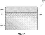
- An interface 132 between the portion 114 of the first substrate and the other substrate 116 may comprise a non-planar surface, such as, for example, a roughened surface.
- the interface 132 may be formed by grinding an end of the portion 114 of the first substrate attached to the polycrystalline table 112 prior to attaching the portion 114 of the first substrate to the other substrate.
- a surface of the other substrate 116 facing the portion 114 of the first substrate may also be subjected to a grinding process.
- a surface of the portion 114 of the first substrate opposing the polycrystalline table 12 may be ground using, for example, a Blanchard grinding process.
- the resulting surface may have an arithmetic mean roughness value, conventionally called "Ra,” of at least 0.254 nm (0.01 ⁇ in) and up to 254 nm (10 ⁇ in).
- An attachment material as has been previously described herein, may be disposed between the roughened portion 114 of the first substrate and the other substrate 116 prior to attachment.
- the portion 114 of the first substrate may then be attached to the other substrate 116 by, for example, brazing, microwave brazing, welding, hot pressing, or using a sintering process, as have been described previously herein.
- a non-planar interface 132 between the portion 114 of the first substrate and the other substrate 116 may enable a stronger attachment to be formed between the portion 114 of the first substrate and the other substrate 116.
- the non-planar interface 132 between the portion 114 of the first substrate and the other substrate 116 may comprise a non-planar interface design, as known in the art.
- an earth-boring tool 134 to which a cutting element 110 (e.g., any of the cutting element 110 and 110' described previously in connection with FIGS. 2, 3 , 6 through 9 , and 17 ) may be attached is shown.
- the earth-boring tool 134 may comprise an earth-boring drill bit and may have a bit body 136 with blades 138 extending from the bit body 136.
- the cutting elements 110 may be secured within pockets 140 formed in the blades 138.
- cutting elements 110 and polycrystalline tables 112 as described herein may be bonded to and used on other types of earth-boring tools, including, for example, roller cone drill bits, percussion bits, core bits, eccentric bits, bicenter bits, reamers, expandable reamers, mills, hybrid bits, and other drilling bits and tools known in the art.
- earth-boring tools including, for example, roller cone drill bits, percussion bits, core bits, eccentric bits, bicenter bits, reamers, expandable reamers, mills, hybrid bits, and other drilling bits and tools known in the art.
Landscapes
- Engineering & Computer Science (AREA)
- Chemical & Material Sciences (AREA)
- Mechanical Engineering (AREA)
- General Engineering & Computer Science (AREA)
- Materials Engineering (AREA)
- Life Sciences & Earth Sciences (AREA)
- Geology (AREA)
- Mining & Mineral Resources (AREA)
- Organic Chemistry (AREA)
- Metallurgy (AREA)
- Environmental & Geological Engineering (AREA)
- Geochemistry & Mineralogy (AREA)
- General Life Sciences & Earth Sciences (AREA)
- Fluid Mechanics (AREA)
- Physics & Mathematics (AREA)
- Ceramic Engineering (AREA)
- Crystallography & Structural Chemistry (AREA)
- Manufacturing & Machinery (AREA)
- Inorganic Chemistry (AREA)
- Earth Drilling (AREA)
- Photovoltaic Devices (AREA)
- Polishing Bodies And Polishing Tools (AREA)
- Apparatuses And Processes For Manufacturing Resistors (AREA)
- Catalysts (AREA)
- Electric Connection Of Electric Components To Printed Circuits (AREA)
- Pressure Sensors (AREA)
Description
- Embodiments of the present invention relate generally to bearings and cutting elements for earth-boring tools and to methods of forming such bearings and cutting elements. Specifically, embodiments of the disclosure relate to methods of attaching a polycrystalline table to a substrate and bearings and cutting elements formed by such methods.
- Earth-boring tools for forming wellbores in subterranean earth formations may include a plurality of cutting elements secured to a body. For example, fixed-cutter earth-boring rotary drill bits (also referred to as "drag bits") include a plurality of cutting elements that are fixedly attached to a bit body of the drill bit. Similarly, roller cone earth-boring rotary drill bits may include cones that are mounted on bearing pins extending from legs of a bit body such that each cone is capable of rotating about the bearing pin on which it is mounted. A plurality of cutting elements may be mounted to each cone of the drill bit.
- The cutting elements used in such earth-boring tools often include polycrystalline diamond compact (often referred to as "PDC") cutting elements, also termed "cutters," which are cutting elements that include a polycrystalline diamond (PCD) material, which may be characterized as a superabrasive or superhard material. Such polycrystalline diamond materials are formed by sintering and bonding together relatively small synthetic, natural, or a combination of synthetic and natural diamond grains or crystals, termed "grit," under conditions of high temperature and high pressure in the presence of a catalyst, such as, for example, cobalt, iron, nickel, or alloys and mixtures thereof, to form a layer of polycrystalline diamond material, also called a diamond table. These processes are often referred to as high temperature/high pressure (HTHP) processes. The cutting element substrate may comprise a cermet material, i.e., a ceramic-metal composite material, such as, for example, cobalt-cemented tungsten carbide. In some instances, the polycrystalline diamond table may be formed on the cutting element, for example, during the HTHP sintering process. In such instances, cobalt or other catalyst material in the cutting element substrate may be swept into the diamond grains or crystals during sintering and serve as a catalyst material for forming a diamond table from the diamond grains or crystals. Powdered catalyst material may also be mixed with the diamond grains or crystals prior to sintering the grains or crystals together in an HTHP process. In other methods, however, the diamond table may be formed separately from the cutting element substrate and subsequently attached thereto.
- Various methods of forming a polycrystalline diamond element that is thermally stable, including sintering diamond powder in the presence of tungsten carbide, are disclosed in
WO 2010/129813 . - Another method of forming a polycrystalline diamond element body on a substrate with complimentary interfacing surface features is disclosed in
GB 2438073 - The present invention provides a method of forming a polycrystalline element in accordance with claim 1.
- While the specification concludes with claims particularly pointing out and distinctly claiming that which is regarded as the present invention, various features and advantages of embodiments of this invention may be more readily ascertained from the following description of embodiments of the invention when read in conjunction with the accompanying drawings, in which:
-
FIG. 1 is a cross-sectional view of a roller cone of an earth-boring rotary drill bit; -
FIG. 2 illustrates a perspective view of a cutting element having a disc-shaped polycrystalline table according to an embodiment of the disclosure; -
FIG. 3 illustrates a perspective view of a cutting element having a dome-shaped polycrystalline table according to another embodiment of the disclosure; -
FIG. 4 illustrates an exploded perspective view of an axial bearing according to an embodiment of the disclosure; -
FIG. 5 illustrates an exploded perspective view of a radial bearing according to another embodiment of the disclosure; -
FIG. 6 illustrates a cross-section of a cutting element having a dome-shaped polycrystalline table according to an embodiment of the disclosure; -
FIG. 7 illustrates a cross-section of another cutting element having a dome-shaped polycrystalline table according to another embodiment of the disclosure; -
FIG. 8 illustrates a cross-section of a cutting element having a disc-shaped polycrystalline table according to an embodiment of the disclosure; -
FIG. 9 illustrates a cross-section of a cutting element having a polycrystalline table according to another embodiment of the disclosure; -
FIGS. 10 through 13 illustrate schematically a method of attaching a polycrystalline table to a substrate according to the present invention; -
FIGS. 14 through 16 illustrate schematically another method of attaching a polycrystalline table to a substrate in accordance with an embodiment of the disclosure; -
FIG. 17 illustrates a simplified cross-sectional view of an interface between a portion of a first substrate and a second substrate in accordance with an embodiment of the disclosure; and -
FIG. 18 depicts another earth-boring tool to which at least one cutting element comprising a polycrystalline table of the disclosure may be attached. - The illustrations presented herein are not meant to be actual views of any particular earth-boring tool, cutting element, or bearing, but are merely idealized representations that are employed to describe the embodiments of the disclosure. Additionally, elements common between figures may retain the same or similar numerical designation.
- Although some embodiments of the disclosure are depicted as being used and employed in earth-boring drill bits, such as earth-boring rotary drill bits, sometimes referred to as "roller cone" or "rolling cone" bits, persons of ordinary skill in the art will understand that diamond-bearing structures in accordance with the disclosure may be employed in any earth-boring tool employing a structure comprising a polycrystalline superabrasive material attached to a supporting substrate. Accordingly, the terms "earth-boring tool" and "earth-boring drill bit," as used herein, mean and include any type of bit or tool used for drilling during the formation or enlargement of a wellbore in a subterranean formation and include, for example, fixed-cutter bits, percussion bits, core bits, eccentric bits, bicenter bits, reamers, mills, drag bits, hybrid bits, and other drilling bits and tools known in the art.
- As used herein, the term "polycrystalline table" means and includes any structure comprising a plurality of grains (i.e., crystals) of superabrasive, also known in the art as superhard, material that are bonded directly together by inter-granular bonds. The crystal structures of the individual grains of the material may be randomly oriented in space within the polycrystalline material.
- As used herein, the term "inter-granular bond" means and includes any direct atomic bond (e.g., covalent, metallic, etc.) between atoms in adjacent grains of superabrasive material.
- Referring to
FIG. 1 , a cross-sectional view of aroller cone 102 of an earth-boringrotary drill bit 100, commonly termed a "rock" bit, is shown. The earth-boringrotary drill bit 100 includes a bit body (not shown) havinglegs 104 depending from the body. Aroller cone 106 is rotatably mounted to abearing pin 108 on each of thelegs 104. Eachroller cone 106 may comprise a plurality of cutting elements, such asinserts 110 disposed in recesses formed in theroller cone 106 and attached to theroller cone 106. Eachinsert 110 may comprise a polycrystalline table 112 attached to a portion 114 (e.g., a layer) of a first substrate. Theportion 114 of the first substrate may be attached to anothersubstrate 116. Thedrill bit 100 also comprises a bearing system. The bearing system includes aradial bearing assembly 118 and an axial bearingassembly 120. Theradial bearing assembly 118 and the axial bearingassembly 120 may comprise abutting polycrystalline tables 112 attached toportions 114 of first substrates. Eachportion 114 of a first substrate may be attached to anothersubstrate 116. The abutting polycrystalline tables 112 may be configured to rotate slidably against one another. - As the
drill bit 100 rotates, theroller cone 102 may rotate about thebearing pin 108 and roll around a bottom of a wellbore. The polycrystalline tables 112 ofinserts 110 may impact and crush an underlying earth formation. In addition, the radial bearingassembly 118 may bear radial forces acting on theroller cone 102 as its abutting polycrystalline tables 112 slide against one another. The axial bearingassembly 120 may bear axial forces acting on theroller cone 102 as its abutting polycrystalline tables 112 slide against one another. - Referring to
FIG. 2 , a cutting element 110' according to an embodiment of the disclosure is shown. The cutting element 110' comprises a polycrystalline table 112 attached to aportion 114 of a first substrate, another portion opposite that to which polycrystalline table 112 is attached having been removed.Portion 114 may also be characterized as a residual substrate. Theportion 114 of the first substrate is attached, in turn, to anothersubstrate 116. Thus, theportion 114 of the first substrate is interposed between the polycrystalline table 112 and theother substrate 116. The cutting element 110' may be substantially cylindrical, thesubstrate 116 comprising a cylinder, the polycrystalline table 112 comprising a disc, and theportion 114 of the first substrate comprising a disc. In some embodiments, a chamfer or beveled edge may be disposed between a side surface and a cutting face of the polycrystalline table 112. The cutting element 110' may comprise a cutting element 110' conventionally attached to and deployed with a fixed-cutter earth-boring drill bit, which is also commonly termed a "drag" bit. - Referring to
FIG. 3 , aninsert 110 according to another embodiment of the disclosure is shown. Theinsert 110 comprises a polycrystalline table 112 attached to aportion 114 of a first substrate. Theportion 114 of the first substrate is attached, in turn, to anothersubstrate 116. Thus, theportion 114 of the first substrate is interposed between the polycrystalline table 112 and theother substrate 116. Thesubstrate 116 comprises a cylinder and theportion 114 of the first substrate comprises a disc disposed on the substrate. The polycrystalline table 112 comprises a hemisphere. Thus, theinsert 110 may comprise a dome-shaped cutting surface. In other embodiments, the polycrystalline table 112 may comprise, for example, a chisel shape, a tombstone shape, or other cutting shapes and surfaces known in the art. Theinsert 110 may be of a type typically attached to and deployed with aroller cone 102 of an earth-boring rotary drill bit 100 (seeFIG. 1 ). - Referring to
FIG. 4 , anaxial bearing assembly 120 according to an embodiment of the disclosure is shown. Theaxial bearing assembly 120 may be configured to accommodate axial forces acting on theaxial bearing assembly 120 during relative movement of the components thereof. Theaxial bearing assembly 120 comprises two opposing polycrystalline tables 112. The polycrystalline tables 112 may comprise discs. When in use, opposing flat, circular surfaces of the polycrystalline tables 112 may abut against one another. The opposing flat, circular surfaces of the polycrystalline tables 112 may slide against one another as at least one of the polycrystalline tables 112 rotates about its central longitudinal axis. In accordance with the invention, each polycrystalline table 112 is attached to aportion 114 of a first substrate. Theportion 114 of the first substrate is attached, in turn, to anothersubstrate 116. Thus, theportion 114 of the first substrate is interposed between the polycrystalline table 112 and theother substrate 116. Theportion 114 of the first substrate may comprise a disc, and theother substrate 116 may comprise a cylinder. Thus, theaxial bearing assembly 120 may comprise two opposing cylinders. - Referring to
FIG. 5 , aradial bearing assembly 118 according to an embodiment of the disclosure is shown. Theradial bearing assembly 118 may be configured to accommodate radial forces acting on theradial bearing assembly 118 during relative movement of the components thereof. Theradial bearing assembly 118 comprises a plurality of opposing polycrystalline tables 112. The polycrystalline tables 112 may comprise bearing pads. When in use, a radially outer surface of one polycrystalline table 112 may abut against a radially inner surface of the other polycrystalline table 112, the one polycrystalline table 112 being concentrically nested within the other polycrystalline table 112. The opposing surfaces of the polycrystalline tables 112 may slide against one another as at least some of the polycrystalline tables 112 rotate about a central axis of theradial bearing assembly 118. Each polycrystalline table 112 is attached to aportion 114 of a first substrate. Theportion 114 of the first substrate is attached, in turn, to anothersubstrate 116. Thus, theportion 114 of the first substrate is interposed between the polycrystalline table 112 and theother substrate 116. Each of theportions 114 of the first substrate and theother substrate 116 may comprise annular members disposed radially adjacent to one another. Theportion 114 of the first substrate and theother substrate 116 may comprise, therefore, concentric rings having polycrystalline tables attached to theportions 114 of the first substrates thereof. Thus, theradial bearing assembly 118 may comprise two concentrically nested annular members. - The polycrystalline table 112 of any of the embodiments shown in
FIGS. 2 through 5 comprise a superabrasive, sometimes referred to as superhard, material. For example, the polycrystalline table 112 may comprise synthetic diamond, natural diamond, a combination of synthetic diamond and natural diamond, cubic boron nitride, or other superabrasive materials known in the art. In some embodiments, the polycrystalline table 112 may comprise a plurality of interbonded grains of superabrasive material of at least substantially uniform size. In other embodiments, the polycrystalline table 112 may comprise a plurality of interbonded grains of superabrasive material of non-uniform size. For example, interbonded grains of superabrasive material of different sizes (i.e., grains having a multi-modal size distribution) may be interspersed throughout the polycrystalline table in a substantially uniform fashion. As another example, interbonded grains of superabrasive material may be disposed in layers, each layer having a different average grain size, to form a layered polycrystalline table. As a yet further example, interbonded grains of superabrasive material may be graded, the average grain size gradually increasing or decreasing in a direction through the polycrystalline table 112. - The
portion 114 of the first substrate and theother substrate 116 may comprise a hard material. The hard material may comprise, for example, a ceramic-metal composite material (i.e., a "cermet" material) comprising a plurality of hard ceramic particles dispersed throughout a metal matrix material. The hard ceramic particles may comprise carbides, nitrides, oxides, and borides (including boron carbide (B4C)). More specifically, the hard ceramic particles may comprise carbides and borides made from elements such as W, Ti, Mo, Nb, V, Hf, Ta, Cr, Zr, Al, and Si. By way of example and not limitation, materials that may be used to form hard ceramic particles include tungsten carbide (WC, W2C, and combinations of WC and W2C), titanium carbide (TiC), tantalum carbide (TaC), titanium diboride (TiB2), chromium carbides, titanium nitride (TiN), aluminium oxide (Al2O3), aluminium nitride (AlN), and silicon carbide (SiC). The metal matrix material of the ceramic-metal composite material may include, for example, cobalt-based, iron-based, nickel-based, iron- and nickel-based, cobalt- and nickel-based, and iron- and cobalt-based alloys. The matrix material may also be selected from commercially pure elements such as, for example, cobalt, iron, and nickel. For example, the hard material may comprise a plurality of tungsten carbide particles in a cobalt matrix. In some embodiments, theportion 114 of the first substrate and theother substrate 116 may comprise hard particles of at least substantially uniform size. In other embodiments, theportion 114 of the first substrate and theother substrate 116 may comprise hard particles having a multi-modal size distribution. In some embodiments, an average particle size of hard particles of theportion 114 of the first substrate may be substantially equal to an average particle size of hard particles of theother substrate 116. In other embodiments, the average particle size of hard particles of theportion 114 of the first substrate may substantially differ from the average particle size of hard particles of theother substrate 116. For example, the average particle size of hard particles of theportion 114 of the first substrate may be substantially greater than, such as, for example, at least two times greater than, the average particle size of hard particles of theother substrate 116. - Referring to
FIG. 6 , a cross-section of aninsert 110 cutting element having a dome-shaped polycrystalline table 112 is shown. Theinsert 110 comprises a polycrystalline table 112 attached to aportion 114 of a first substrate. The polycrystalline table 112 comprises a hollow dome shape, and theportion 114 of the first substrate comprises a dome-shaped protrusion abutting the polycrystalline table 112. Theportion 114 of the first substrate may comprise anintermediate layer 115 adjacent the polycrystalline table 112. Theintermediate layer 115 may comprise a mixture of particles comprising a superabrasive material and particles comprising a hard material, as described previously herein. Theintermediate layer 115 may comprise a graded layer of theportion 114 of the first substrate to transition from the material of the polycrystalline table 112 to the material of a remainder of theportion 114 of the first substrate. In other embodiments, multipleintermediate layers 115 may be provided with theportion 114 of the first substrate. Theportion 114 of the first substrate is attached to anothersubstrate 116. Thus, theportion 114 of the first substrate is interposed between the polycrystalline table 112 and theother substrate 116. - Referring to
FIG. 7 , a cross-section of anotherinsert 110 cutting element having a dome-shaped polycrystalline table 112 is shown. Theinsert 110 comprises a polycrystalline table 112 attached to aportion 114 of a first substrate. The polycrystalline table 112 comprises a solid dome shape, such as, for example, a hemisphere. The polycrystalline table 112 may be attached to a substantially disc-shapedportion 114 of a first substrate. Theportion 114 of the first substrate is attached, in turn, to anothersubstrate 116. Thus, theportion 114 of the first substrate is interposed between the polycrystalline table 112 and theother substrate 116. - Referring to
FIG. 8 , a cross-section of a cutting element 110' having a disc-shaped polycrystalline table 112 is shown. The cutting element 110' comprises a polycrystalline table 112 attached to aportion 114 of a first substrate. The polycrystalline table 112 comprises a cylinder or disc shape. Theportion 114 of the first substrate likewise comprises a cylinder or disc shape. Aninterface 117 between the polycrystalline table 112 and theportion 114 of the first substrate may be planar or substantially planar. Theportion 114 of the first substrate is attached to anothersubstrate 116. Thus, theportion 114 of the first substrate is interposed between the polycrystalline table 112 and theother substrate 116. - Referring to
FIG. 9 , a cross-section of another cutting element 110' having a polycrystalline table 112 is shown. The cutting element 110' comprises a polycrystalline table attached to aportion 114 of a first substrate. The polycrystalline table 112 comprises a substantially cylinder or substantially disc-like shape. Likewise, theportion 114 of the first substrate comprises a substantially cylinder or substantially disc-like shape. Aninterface 117 between the polycrystalline table 112 and theportion 114 of the first substrate may comprise a non-planar interface design, such as, for example, alternating protrusions and recesses, an annulus, radially extending spokes, or other non-planar interface designs known in the art. Theportion 114 of the first substrate is attached to anothersubstrate 116. Thus, theportion 114 of the first substrate is interposed between the polycrystalline table 112 and theother substrate 116. - Referring to
FIGS. 10 through 13 , a method of attaching a polycrystalline table to a substrate according to the present invention is shown. Shown inFIG. 10 is anintermediate structure 122 in the process of forming a cutting element or other structure comprising a polycrystalline table attached to a substrate. Theintermediate structure 122 comprises a polycrystalline table 112 attached to afirst substrate 124. Theintermediate structure 122 may be formed, for example, by disposing a mass of hard material, a plurality of particles comprising a superabrasive material, and a catalyst material into a mold. The hard material may comprise, for example, any of the hard materials described previously. As a specific, non-limiting example, the hard material may comprise a plurality of tungsten carbide particles in a cobalt matrix, known in the art as cobalt-cemented tungsten carbide. The hard material may be present in the form of a fully sintered (i.e., having a final density) part. The superabrasive material may comprise, for example, any of the superabrasive materials described previously. The catalyst material may comprise, for example, an alloy (e.g., cobalt-based, iron-based, nickel-based, iron and nickel-based, cobalt and nickel-based, and iron and cobalt-based alloys) or a commercially pure element (e.g., cobalt, iron, and nickel) that catalyzes grain growth and intergranular bonding. - The superabrasive particles may be layered on an end of a mass of the hard particles, and the particles comprising a catalyst material may be dispersed among the hard particles and, optionally, among the superabrasive particles. In another embodiment, a preformed substrate of hard particles may be placed in a mold and superabrasive particles may be placed over the substrate. Catalyst material may reside in the substrate, be dispersed among the superabrasive particles, or placed between the superabrasive particles and an adjacent end of the substrate, all as known in the art.
- A sintering process, such as, for example, an HTHP process, as known in the art, may be applied to the particles in the mold. In some embodiments, the pressure used in the sintering process may be at least five gigapascals (5 GPa). For example, the peak pressure may be eight gigapascals (8 GPa) or even ten gigapascals (10 GPa). As a result of the sintering process, a polycrystalline table 112 comprising a superabrasive material may be formed on a
first substrate 124 comprising a hard material. - As shown in
FIG. 11 , the polycrystalline table 112 and aportion 114 of thefirst substrate 124 are removed from a remainder of thefirst substrate 124. Theportion 114 of thefirst substrate 124 may remain attached to the polycrystalline table. The polycrystalline table 112 and theportion 114 of thefirst substrate 124 may be removed from the remainder of thefirst substrate 124 using, for example, electric discharge machining (EDM), a diamond saw, grinding, or other methods for machining hard substrates known in the art. The thickness "t" of theportion 114 of thefirst substrate 124 may be minimized in some embodiments. For example, theportion 114 of thefirst substrate 124 may have a thickness t less than one millimeter (1 mm). In other embodiments, however, the thickness t of theportion 114 of thefirst substrate 124 may not be minimized. For example, theportion 114 of thefirst substrate 124 may have a thickness t greater than one millimeter (1 mm). In alternative arrangements, outside the scope of the present invention, the polycrystalline table may be formed on a first substrate having a reduced thickness t, rather than forming the polycrystalline table on a first substrate and removing a remainder of the first substrate to the reduced thickness t. - The polycrystalline table 112 and the
portion 114 of thefirst substrate 124 are then be leached to remove catalyst material therefrom. The leached polycrystalline table 112 and the leachedportion 114 of afirst substrate 124 attached to the polycrystalline table 112 are shown inFIG. 12 . Catalyst material disposed in interstitial spaces between interbonded grains of the superabrasive material of the polycrystalline table 112 and disposed in spaces between hard particles of theportion 114 of thefirst substrate 124 may be removed, for example, using aqua regia, or other leaching agents or methods known in the art. In some embodiments, catalyst material may be substantially completely leached from both the polycrystalline table 112 and theportion 114 of thefirst substrate 124 attached thereto. In other embodiments, at least some catalyst material may remain in theportion 114 of thefirst substrate 124 attached to the polycrystalline table 112. In still other embodiments, at least some catalyst material may remain in the polycrystalline table 112 as well. Penetration of the leaching agent may be controlled to leach only a selected portion of the polycrystalline table 112, theportion 114 of thefirst substrate 124, or both. In one embodiment, the polycrystalline table may have catalyst removed therefrom to a depth of between, for example, about 0.04 mm and 0.5 mm from the cutting face and side surface. - In one embodiment, for example, the average grain size of the interbonded grains of the polycrystalline table 112 and the average particle size of the hard particles of the
portion 114 of thefirst substrate 124 may be selected to provide a desired volume percentage of interstitial spaces between the interbonded grains and the hard particles, in which catalyst material may be disposed. As another example, the average grain size of the interbonded grains of the polycrystalline table 112 and the average particle size of the hard particles of theportion 114 of thefirst substrate 124 may be selected to provide a desired permeability. A leach rate may be determined based on the desired volume percentage of interstitial spaces in which catalyst material may be disposed or based on the desired permeability and used to determine how long to leach in order to achieve a selected leach depth. In yet further embodiments, the polycrystalline table 112 and theportion 114 of thefirst substrate 124 attached thereto may not be subjected to a leaching process. - In embodiments where a leaching process is used to remove catalyst material from at least one of the polycrystalline table 112 and the
portion 114 of thefirst substrate 124, at least a portion of the polycrystalline table 112 and/or theportion 114 of thefirst substrate 124 that has been leached may, optionally, be reinfiltrated. For example, a material may be reinfiltrated into theportion 114 of thefirst substrate 124, leaving the interstitial spaces between interbonded grains of the polycrystalline table 112 devoid of other material (i.e., filled with air or other environmental fluids). The material reinfiltrated into the polycrystalline table 112 and/or theportion 114 of thefirst substrate 124 may comprise a catalyst material or an inert material. As a non-limiting example, silicon (Si) may be reinfiltrated into at least a portion of the polycrystalline table 112 and/or theportion 114 of thefirst substrate 124 that has been leached. - In addition, leaching may remove material that acted as a binder to provide structural integrity to the structure of the polycrystalline table 112 and the
portion 114 of thefirst substrate 124. Further, residual stresses may weaken theportion 114 of thefirst substrate 124 after leaching, potentially to the point of damaging theportion 114. Placing theportion 114 of thefirst substrate 124 in a state of compression, for example, by disposing a ring around the periphery of theportion 114 of thefirst substrate 124 may enable theportion 114 of thefirst substrate 124 to maintain its structural integrity during and after leaching. In some embodiments, the ring may comprise a ceramic or carbide ring that has been shrink fit around at least theportion 114 of thefirst substrate 124 and, optionally, around the polycrystalline table 112. In other embodiments, the polycrystalline table 112 may be oversized and comprise an annular portion that extends at its periphery down and around theportion 114 of the first substrate. The ring or annular portion of the polycrystalline table 112 may be subsequently removed once sufficient structural integrity has been achieved, for example, by reinfiltrating as described above or by attachment to another substrate as described below. - As shown in
FIG. 13 , the polycrystalline table 112 and theportion 114 of thefirst substrate 124 are attached to anothersubstrate 116 to form a cutting element 110'. In other embodiments, a portion of a first substrate attached to a polycrystalline table may be attached to another substrate to form an axial bearing or a radial bearing. Theportion 114 of thefirst substrate 124 may be directly attached to theother substrate 116. Thus, theportion 114 of thefirst substrate 124 is interposed between the polycrystalline table 112 and theother substrate 116. Theportion 114 of thefirst substrate 124 attached to the polycrystalline table 112 may be attached to theother substrate 116 by, for example, brazing, microwave brazing, welding, hot pressing, or using a sintering process. For example, an HTHP process, as known in the art, may be applied to the components in a mold. In some embodiments, the pressure used in the sintering process may be at least five gigapascals (5 GPa). For example, the peak pressure may be eight gigapascals (8 GPa) or even ten gigapascals (10 GPa). - The material composition of the
portion 114 of thefirst substrate 124 may be selected to optimize attachment to the polycrystalline table 112 and subsequent attachment to theother substrate 116. For example, theportion 114 of thefirst substrate 124 may comprise a greater volume percentage of catalyst material than theother substrate 116 prior to leaching, enabling theportion 114 of thefirst substrate 124 to adequately catalyze formation of the polycrystalline table 112 while theother substrate 116 provides additional structural strength and durability to theinsert 110. Theportion 114 of thefirst substrate 124, therefore, may enable formation of a polycrystalline table 112 attached thereto while facilitating attachment to anothersubstrate 116 to increase strength and durability of the resulting structure. In particular, theportion 114 of thefirst substrate 124 may enable the polycrystalline table 112 to be reattached to anothersubstrate 116 while retaining a stronger attachment between the polycrystalline table 112 and theportion 114 of thefirst substrate 124. - In embodiments where the polycrystalline table 112 and the
portion 114 of thefirst substrate 124 are attached to theother substrate 116 using a sintering process, catalyst material may be swept from theother substrate 116 into theportion 114 of thefirst substrate 124 and the polycrystalline table 112. Catalyst material remaining in theportion 114 of thefirst substrate 124 may also be swept from theportion 114 of thefirst substrate 124 into the polycrystalline table 112. The catalyst material from theother substrate 116 may be a different catalyst material than the catalyst material used initially to form the polycrystalline table 112. For example, the polycrystalline table 112 may be formed in the presence of a cobalt-based alloy, which may then be at least substantially removed from the polycrystalline table, and the catalyst material swept from theother substrate 116 into the polycrystalline table 112 may comprise a nickel-based alloy. As another example, the polycrystalline table 112 may be formed in the presence of a cobalt-based alloy, which may then be at least substantially removed from the polycrystalline table, and the catalyst material swept from theother substrate 116 into the polycrystalline table 112 may comprise commercially pure cobalt. The polycrystalline table 112 may subsequently be subjected to another leaching process to remove catalyst material from at least a portion thereof. For example, catalyst material may be removed from a cuttingface 125 of the polycrystalline table 112 to a selected depth d1 within the polycrystalline table 112. The cuttingface 125 may be substantially free of catalyst material. As another example, catalyst material may also be removed from aside surface 127 of the polycrystalline table 112 to a selected depth d2 within the polycrystalline table 112. - Referring to
FIGS. 14 through 16 , another method of attaching a polycrystalline table to a substrate according to another embodiment of the disclosure is shown schematically. Shown inFIG. 14 is anintermediate structure 122 in the process of forming a cutting element or other structure comprising a polycrystalline table attached to a substrate. Theintermediate structure 122 comprises a polycrystalline table 112 attached to afirst substrate 124. Theintermediate structure 122 may be formed, for example, by disposing hard particles, such as, for example, particles of tungsten carbide, superabrasive particles, such as, for example, natural diamond particles, synthetic diamond particles, a combination of natural and synthetic diamond particles, and particles comprising a catalyst material, such as, for example, cobalt particles, into a mold. The superabrasive particles may be layered on an end of the hard particles, and the particles comprising a matrix material may be dispersed among the superabrasive particles and the hard particles. A sintering process, such as, for example an HTHP process as known in the art, may be applied to the particles in the mold. In some embodiments, the pressure applied to the particles in the mold may exceed five gigapascals (5 GPa). For example, the pressure applied to the particles in the mold may comprise eight gigapascals (8 GPa) or even ten gigapascals (10 GPa). As a result, a polycrystalline table 112 comprising a superabrasive material may be formed on afirst substrate 124 comprising a hard material. - As shown in
FIG. 15 , the polycrystalline table 112 and aportion 114 of thefirst substrate 124 is removed from a remainder of thefirst substrate 124. Theportion 114 of thefirst substrate 124 may remain attached to the polycrystalline table. The polycrystalline table 112 and theportion 114 of thefirst substrate 124 may be removed using, for example, EDM, a diamond saw, grinding, or other hard substrate machining processes known in the art. The thickness t of theportion 114 of thefirst substrate 124 may comprise up to about two-thirds (2/3) of the total thickness of the resulting structure, in this embodiment of the resulting cutting element. In alternative embodiments, the polycrystalline table may be formed on a first substrate having a reduced thickness t, rather than forming the polycrystalline table on a first substrate and removing a remainder of the first substrate to the reduced thickness t. - A
recess 126, as shown inFIG. 16 , may be formed at least partially through the thickness t of theportion 114 of thefirst substrate 124. Therecess 126 may comprise a blind bore formed from a surface of theportion 114 of thefirst substrate 124 opposing the polycrystalline table 112 to a selected depth (e.g., depth d1 and/or depth d2, as shown inFIG. 16 ) within the thickness t of theportion 114 of thefirst substrate 124. Therecess 126 may comprise, for example, a cylindrical or substantially cylindrical hole formed in theportion 114 of thefirst substrate 124. Therecess 126 may be formed using plunge EDM, laser machining, carbide ultrasonic machining, a combination of any of plunge EDM, laser machining, and carbide ultrasonic machining, or any other process for forming a recess in a hard substrate known in the art. Thus, theportion 114 of thefirst substrate 124 may comprise an annular member attached at a periphery of the polycrystalline table 112. In some embodiments, the recess may extend through theportion 114 of thefirst substrate 124 to terminate at the polycrystalline table 112. In other embodiments, the recess may extend into theportion 114 of thefirst substrate 124 and terminate within theportion 114 adjacent to the polycrystalline table 112. Though therecess 126 is shown as a substantially cylindrical bore extending into theportion 114 of thefirst substrate 124, other non-planar interface designs, such as, for example, radially extending spokes, an annulus, or other shapes as known in the art, may be similarly used. Aprotrusion 128 may be correspondingly formed in anothersubstrate 116 to which theportion 114 of thefirst substrate 124 is to be attached after the catalyst removal process. Theprotrusion 128 may comprise, for example, a radially smaller cylinder protruding from a radially larger portion of theother substrate 116. Theprotrusion 128 may be configured to be received within therecess 126. - The polycrystalline table 112 and the
portion 114 of thefirst substrate 124 are then be leached to remove catalyst material therefrom. Catalyst material disposed in interstitial spaces between interbonded grains of the superabrasive material of the polycrystalline table 112 and disposed in spaces between hard particles of theportion 114 of thefirst substrate 124 may be removed, for example, using aqua regia, or other leaching agents or methods known in the art. In some embodiments, catalyst material may be substantially completely leached from both the polycrystalline table 112 and theportion 114 of thefirst substrate 124 attached thereto. In other embodiments, at least some catalyst material may remain in theportion 114 of thefirst substrate 124 attached to the polycrystalline table 112. For example, all or substantially all of the catalyst material may remain in theportion 114 of thefirst substrate 124 while the polycrystalline table 112 is fully or substantially fully leached. In still other embodiments, at least some catalyst material may remain in the polycrystalline table 112 as well. Penetration of the leaching agent may be controlled to leach only a selected portion of the polycrystalline table 112, theportion 114 of thefirst substrate 124, or both. - The
portion 114 of thefirst substrate 124 may be configured to enable leaching of the polycrystalline table 112. For example, where theportion 114 of thefirst substrate 124 comprises an annular structure having arecess 126 formed therein and extending to the polycrystalline table attached thereto, the recess may enable a leaching agent to flow to the polycrystalline table 112 without having to pass through the material of theportion 114 of thefirst substrate 124 or without having to pass through all of the material of theportion 114 of thefirst substrate 124. In this way, therecess 126 may enable the leaching agent to remove all or substantially all the catalyst material from the polycrystalline table 112 while leaving a substantial portion of the catalyst material in the annular structure of theportion 114 of thefirst substrate 124. Theportion 114 of thefirst substrate 124 may also enhance the mechanical integrity and facilitate handling of theportion 114 of thefirst substrate 124 and attached polycrystalline table 112 because the thickness t of theportion 114 of thefirst substrate 124 may comprise up to about two-thirds (2/3) of the total thickness of the resulting structure, such as, for example, insert 110. - An
attachment material 130 may be optionally disposed over a portion of theother substrate 116 to which theportion 114 of thefirst substrate 124 is to be attached. For example, theattachment material 130 may comprise a metal foil layer, such as, for example, a catalyst foil layer, disposed over theprotrusion 128 and a surrounding annular surface of theother substrate 116 facing theportion 114 of thefirst substrate 124. In some embodiments, theattachment material 130 may comprise, for example, a braze material. In embodiments where theattachment material 130 comprises a catalyst material, the catalyst material of theattachment material 130 may be a different catalyst material than the catalyst material used to form the polycrystalline table 112. In other embodiments, theattachment material 130 may comprise an organic adhesive, such as, for example, a gum, a glue (e.g., the alcohol-catalyzed α-cyanoacrylate adhesive compositions disclosed inU.S. Patent No. 2,768,109 issued October 23, 1956 to Coover ), a bond, an epoxy, or any other material formed from organic chemical precursors that forms attachments, such as, for example, by crosslinking to bond. In still further embodiments, theattachment material 130 may comprise an organo-metallic adhesive, such as, for example, the organo-metallic adhesive composition disclosed inU.S. Patent No. 4,808,659 issued February 28, 1989 to Nishihara et al. - As shown in
FIG. 16 ,recess 126 may be axially aligned with theprotrusion 128. Theportion 114 of thefirst substrate 124 may be lowered over theother substrate 116 until theprotrusion 128 is located within therecess 126. Theoptional attachment material 130 may be interposed between theportion 114 of thefirst substrate 124 and theother substrate 116. Theportion 114 of thefirst substrate 124 is then be attached to the other substrate to form a cutting element or other structure comprising a polycrystalline table 112 attached to a substrate. In other embodiments, a portion of a first substrate attached to a polycrystalline table may be attached to another substrate to form an axial bearing or a radial bearing. In some embodiments, theportion 114 of thefirst substrate 124 may be directly attached to theother substrate 116. Thus, theportion 114 of thefirst substrate 124 may be interposed between the polycrystalline table 112 and theother substrate 116. In other embodiments, theprotrusion 128 of theother substrate 116 may contact and be attached directly to the polycrystalline table 112, for example, when theprotrusion 128 extends through therecess 126 formed in theportion 114 of thefirst substrate 124. Theportion 114 of thefirst substrate 124 attached to the polycrystalline table 112 may be attached to theother substrate 116 by, for example, brazing, microwave brazing, welding, hot pressing, or using a sintering process. For example, an HTHP process, as known in the art, may be applied to the polycrystalline table 112, theportion 114 of thefirst substrate 124 and theother substrate 116 in a mold. In some embodiments, the pressure used in the sintering process may be at least five gigapascals (5 GPa). For example, the peak pressure may be eight gigapascals (8 GPa) or even ten gigapascals (10 GPa). - In embodiments where the polycrystalline table 112 and the
portion 114 of thefirst substrate 124 are attached to theother substrate 116 using a sintering process, catalyst material may be swept from theother substrate 116 into theportion 114 of thefirst substrate 124 and the polycrystalline table 112. Catalyst material remaining in theportion 114 of thefirst substrate 124 may also be swept from theportion 114 of thefirst substrate 124 into the polycrystalline table 112. The catalyst material from theother substrate 116 may be a different catalyst material than the catalyst material used initially to form the polycrystalline table 112. For example, the polycrystalline table 112 may be formed in the presence of a cobalt-based alloy, which may then be at least substantially removed from the polycrystalline table, and the catalyst material swept from theother substrate 116 into the polycrystalline table 112 may comprise a nickel-based alloy. As another example, the polycrystalline table 112 may be formed in the presence of a cobalt-based alloy, which may then be at least substantially removed from the polycrystalline table, and the catalyst material swept from theother substrate 116 into the polycrystalline table 112 may comprise commercially pure cobalt. In some embodiments, theattachment material 130 may also comprise a reinfiltrant, such as, for example, a catalyst material (e.g., cobalt, nickel, iron, alloys of cobalt, nickel, or iron, or other catalysts known in the art) or an inert material (e.g., silicon, aluminum, copper, or other inert reinfiltrants known in the art). Thus, therecess 126 may enable the introduction of a reinfiltrant to the polycrystalline table 112 directly, without having to pass through theportion 114 of thefirst substrate 124 attached thereto. The polycrystalline table 112 may subsequently be subjected to another leaching process to remove catalyst material from at least a portion thereof. For example, catalyst material may be removed from a cuttingface 125 of the polycrystalline table 112 to a selected depth d1 within the polycrystalline table 112. The cuttingface 125 may be substantially free of catalyst material. As another example, catalyst material may also be removed from aside surface 127 of the polycrystalline table 112 to a selected depth d2 within the polycrystalline table 112. - With reference to
FIG. 17 , a cutting element 110' in accordance with an embodiment of the present disclosure is shown. The cutting element 110' comprises a polycrystalline table 112 attached to aportion 114 of a first substrate. Theportion 114 of the first substrate is attached, in turn, to anothersubstrate 116. Thus, theportion 114 of the first substrate is interposed between the polycrystalline table 112 and theother substrate 116. Aninterface 132 between theportion 114 of the first substrate and theother substrate 116 may comprise a non-planar surface, such as, for example, a roughened surface. Theinterface 132 may be formed by grinding an end of theportion 114 of the first substrate attached to the polycrystalline table 112 prior to attaching theportion 114 of the first substrate to the other substrate. In some embodiments, a surface of theother substrate 116 facing theportion 114 of the first substrate may also be subjected to a grinding process. A surface of theportion 114 of the first substrate opposing the polycrystalline table 12 may be ground using, for example, a Blanchard grinding process. The resulting surface may have an arithmetic mean roughness value, conventionally called "Ra," of at least 0.254 nm (0.01 µin) and up to 254 nm (10 µin). An attachment material, as has been previously described herein, may be disposed between the roughenedportion 114 of the first substrate and theother substrate 116 prior to attachment. Theportion 114 of the first substrate may then be attached to theother substrate 116 by, for example, brazing, microwave brazing, welding, hot pressing, or using a sintering process, as have been described previously herein. Anon-planar interface 132 between theportion 114 of the first substrate and theother substrate 116 may enable a stronger attachment to be formed between theportion 114 of the first substrate and theother substrate 116. In other embodiments, thenon-planar interface 132 between theportion 114 of the first substrate and theother substrate 116 may comprise a non-planar interface design, as known in the art. - Referring to
FIG. 18 , an earth-boringtool 134 to which a cutting element 110 (e.g., any of the cuttingelement 110 and 110' described previously in connection withFIGS. 2, 3 ,6 through 9 , and17 ) may be attached is shown. The earth-boringtool 134 may comprise an earth-boring drill bit and may have abit body 136 withblades 138 extending from thebit body 136. The cuttingelements 110 may be secured withinpockets 140 formed in theblades 138. However, cuttingelements 110 and polycrystalline tables 112 as described herein may be bonded to and used on other types of earth-boring tools, including, for example, roller cone drill bits, percussion bits, core bits, eccentric bits, bicenter bits, reamers, expandable reamers, mills, hybrid bits, and other drilling bits and tools known in the art.
Claims (15)
- A method of forming a polycrystalline element, comprising:forming a polycrystalline table comprising catalyst material and interbonded grains of superabrasive material on a first substrate;removing the catalyst material from at least a portion of the polycrystalline table;removing the polycrystalline table and a portion of the first substrate attached to the polycrystalline table from a remainder of the first substrate; andattaching the portion of the first substrate to another substrate; wherein the portion of the first substrate is interposed between the polycrystalline table and the another substrate.
- The method of claim 1, further comprising:disposing at least one of a catalyst material, a braze material, an inert reinfiltrant material, an organic adhesive, and an organo-metallic adhesive between the portion of the first substrate and the another substrate prior to attaching the portion of the first substrate to the another substrate.
- The method of claim 1, further comprising:minimizing a thickness of the portion of the first substrate attached to the polycrystalline table.
- The method of claim 1, 2 or 3, wherein the step of removing the portion of the first substrate from the remainder of the first substrate results in the portion of the first substrate having a reduced thickness.
- The method of claim 1, further comprising:removing catalyst material substantially completely from the polycrystalline table prior to attaching the portion of the first substrate to the another substrate.
- The method of claim 5, further comprising:removing catalyst material from at least part of the portion of the first substrate prior to attaching the portion of the first substrate to the another substrate.
- The method of any one of claims 1 through 6, wherein attaching the portion of the first substrate to another substrate comprises brazing the portion of the first substrate to the another substrate; or
alternatively, wherein attaching the portion of the first substrate to another substrate comprises:disposing the portion of the first substrate attached to the polycrystalline table on the another substrate; andsubjecting the polycrystalline table, the portion of the first substrate, and the another substrate to a high temperature/high pressure (HTHP) process. - The method of any one of claims 1 through 6, further comprising:grinding a surface of the portion of the first substrate opposing the polycrystalline table prior to attaching the portion of the first substrate to the another substrate.
- The method of any one of claims 1 through 6, further comprising: forming a recess to extend at least partially through the portion of the first substrate from an end thereof opposite the polycrystalline table; and
inserting a protrusion of the another substrate into the recess prior to attaching the portion of the first substrate to the another substrate. - The method of any of claims 1 through 6, further comprising:subjecting a plurality of particles comprising the superabrasive material disposed on an end of a mass of hard material to a high temperature/high pressure (HTHP) process in the presence of the catalyst material to form the polycrystalline table attached to the first substrate.
- The method of claim 10, wherein attaching the portion of the first substrate to another substrate comprises brazing the portion of the first substrate to the another substrate; or
alternatively, wherein attaching the portion of the first substrate to another substrate comprises:disposing the portion of the first substrate attached to the polycrystalline table on the another substrate, the portion of the first substrate being interposed between the polycrystalline table and the another substrate; andsubjecting the poly crystalline table, the portion of the first substrate, and the another substrate to another high temperature/high pressure (HTHP) process. - The method of claim 10, further comprising:substantially removing the catalyst material from all of the polycrystalline table prior to attaching the portion of the first substrate to the another substrate; andoptionally, further comprising:removing catalyst material from at least part of the portion of the first substrate prior to attaching the portion of the first substrate to the another substrate.
- The method of any one of claims 10 through 12, further comprising:disposing at least one of a catalyst material, a braze material, an inert reinfiltrant material, an organic adhesive, and an organo-metallic adhesive between the portion of the first substrate and the another substrate prior to attaching the portion of the first substrate to the another substrate.
- The method of any one of claims 10 through 12, further comprising:grinding a surface of the portion of the first substrate opposing the polycrystalline table prior to attaching the portion of the first substrate to the another substrate.
- The method of any one of claims 10 through 12, further comprising:forming a recess to extend at least partially through the portion of the first substrate; andinserting a protrusion of the another substrate at least partially into the recess prior to attaching the portion of the first substrate to the another substrate.
Applications Claiming Priority (2)
| Application Number | Priority Date | Filing Date | Title |
|---|---|---|---|
| US13/040,947 US8882869B2 (en) | 2011-03-04 | 2011-03-04 | Methods of forming polycrystalline elements and structures formed by such methods |
| PCT/US2012/027068 WO2012121940A2 (en) | 2011-03-04 | 2012-02-29 | Methods of forming polycrystalline elements and structures formed by such methods |
Publications (3)
| Publication Number | Publication Date |
|---|---|
| EP2681399A2 EP2681399A2 (en) | 2014-01-08 |
| EP2681399A4 EP2681399A4 (en) | 2014-08-27 |
| EP2681399B1 true EP2681399B1 (en) | 2017-11-08 |
Family
ID=46753500
Family Applications (1)
| Application Number | Title | Priority Date | Filing Date |
|---|---|---|---|
| EP12754871.7A Active EP2681399B1 (en) | 2011-03-04 | 2012-02-29 | Methods of forming polycrystalline elements |
Country Status (11)
| Country | Link |
|---|---|
| US (3) | US8882869B2 (en) |
| EP (1) | EP2681399B1 (en) |
| CN (1) | CN103477017B (en) |
| BR (1) | BR112013022624A2 (en) |
| CA (1) | CA2828866C (en) |
| MX (1) | MX2013010085A (en) |
| NO (1) | NO2798367T3 (en) |
| RU (1) | RU2013144427A (en) |
| SG (1) | SG193269A1 (en) |
| WO (1) | WO2012121940A2 (en) |
| ZA (1) | ZA201306588B (en) |
Families Citing this family (46)
| Publication number | Priority date | Publication date | Assignee | Title |
|---|---|---|---|---|
| ZA201007262B (en) * | 2009-10-12 | 2018-11-28 | Smith International | Diamond bonded construction with reattached diamond body |
| SA111320374B1 (en) | 2010-04-14 | 2015-08-10 | بيكر هوغيس انكوبوريتد | Method Of Forming Polycrystalline Diamond From Derivatized Nanodiamond |
| US20120225277A1 (en) * | 2011-03-04 | 2012-09-06 | Baker Hughes Incorporated | Methods of forming polycrystalline tables and polycrystalline elements and related structures |
| US8882869B2 (en) | 2011-03-04 | 2014-11-11 | Baker Hughes Incorporated | Methods of forming polycrystalline elements and structures formed by such methods |
| US10107042B2 (en) * | 2012-09-07 | 2018-10-23 | Smith International, Inc. | Ultra-hard constructions with erosion resistance |
| US9140072B2 (en) | 2013-02-28 | 2015-09-22 | Baker Hughes Incorporated | Cutting elements including non-planar interfaces, earth-boring tools including such cutting elements, and methods of forming cutting elements |
| US9650836B2 (en) * | 2013-03-01 | 2017-05-16 | Baker Hughes Incorporated | Cutting elements leached to different depths located in different regions of an earth-boring tool and related methods |
| US9534450B2 (en) | 2013-07-22 | 2017-01-03 | Baker Hughes Incorporated | Thermally stable polycrystalline compacts for reduced spalling, earth-boring tools including such compacts, and related methods |
| US20150151409A1 (en) * | 2013-11-30 | 2015-06-04 | Diamond Innovations, Inc. | Aluminum or aluminum carbide alternative catalyst for polycrystalline diamond compact formation |
| US10260560B2 (en) * | 2013-12-04 | 2019-04-16 | Us Synthetic Corporation | Compact bearing assemblies including superhard bearing surfaces, bearing apparatuses, and methods of use |
| US10046441B2 (en) | 2013-12-30 | 2018-08-14 | Smith International, Inc. | PCD wafer without substrate for high pressure / high temperature sintering |
| GB201323169D0 (en) * | 2013-12-31 | 2014-02-12 | Element Six Abrasives Sa | Superhard constructions & methods of making same |
| US9845642B2 (en) | 2014-03-17 | 2017-12-19 | Baker Hughes Incorporated | Cutting elements having non-planar cutting faces with selectively leached regions, earth-boring tools including such cutting elements, and related methods |
| US9605488B2 (en) | 2014-04-08 | 2017-03-28 | Baker Hughes Incorporated | Cutting elements including undulating boundaries between catalyst-containing and catalyst-free regions of polycrystalline superabrasive materials and related earth-boring tools and methods |
| US9714545B2 (en) * | 2014-04-08 | 2017-07-25 | Baker Hughes Incorporated | Cutting elements having a non-uniform annulus leach depth, earth-boring tools including such cutting elements, and related methods |
| WO2015171711A1 (en) | 2014-05-07 | 2015-11-12 | Diamond Innovations, Inc. | Polycrystalline diamond compact with a modified substrate |
| GB2539619A (en) | 2014-06-20 | 2016-12-21 | Halliburton Energy Services Inc | Laser-leached polycrystalline diamond and laser-leaching methods and devices |
| US9309923B1 (en) | 2014-12-05 | 2016-04-12 | Us Synthetic Corporation | Bearing assemblies including integrated lubrication, bearing apparatuses, and methods of use |
| US9523386B1 (en) | 2014-12-05 | 2016-12-20 | Us Synthetic Corporation | Bearing assemblies including integrated lubrication, bearing apparatuses, and methods of use |
| CA2968350A1 (en) * | 2014-12-22 | 2016-06-30 | Halliburton Energy Services, Inc. | Mechanically strengthened bond between thermally stable polycrystalline hard materials and hard composites |
| JP6701742B2 (en) * | 2015-01-14 | 2020-05-27 | 三菱マテリアル株式会社 | Drilling tip and drilling bit |
| CN107438498A (en) * | 2015-05-28 | 2017-12-05 | 哈里伯顿能源服务公司 | Manufacture the induced material segregation method of polycrystalline diamond instrument |
| US10527093B2 (en) * | 2015-07-20 | 2020-01-07 | Us Synthetic Corporation | Bearing assemblies including at least one superhard bearing element having selected surface characteristics and methods of manufacture |
| US10233697B2 (en) * | 2015-09-11 | 2019-03-19 | Baker Hughes Incorporated | Methods of reducing stress in cutting elements for earth-boring tools and resulting cutting elements |
| US11814904B2 (en) * | 2015-11-30 | 2023-11-14 | Schlumberger Technology Corporation | Cutting structure of cutting elements for downhole cutting tools |
| US10519720B2 (en) | 2016-02-18 | 2019-12-31 | Baker Hughes, A Ge Company, Llc | Bearings for downhole tools, downhole tools incorporating such bearings, and related methods |
| US10119335B2 (en) | 2016-02-18 | 2018-11-06 | Baker Hughes Incorporated | Bearings for downhole tools, downhole tools incorporating such bearings, and related methods |
| WO2018124108A1 (en) * | 2016-12-26 | 2018-07-05 | 京セラ株式会社 | Ceramic member and cutting tool |
| US10465775B1 (en) | 2018-07-30 | 2019-11-05 | XR Downhole, LLC | Cam follower with polycrystalline diamond engagement element |
| US11371556B2 (en) | 2018-07-30 | 2022-06-28 | Xr Reserve Llc | Polycrystalline diamond linear bearings |
| US11014759B2 (en) | 2018-07-30 | 2021-05-25 | XR Downhole, LLC | Roller ball assembly with superhard elements |
| US11054000B2 (en) | 2018-07-30 | 2021-07-06 | Pi Tech Innovations Llc | Polycrystalline diamond power transmission surfaces |
| US11187040B2 (en) | 2018-07-30 | 2021-11-30 | XR Downhole, LLC | Downhole drilling tool with a polycrystalline diamond bearing |
| US10738821B2 (en) | 2018-07-30 | 2020-08-11 | XR Downhole, LLC | Polycrystalline diamond radial bearing |
| US11286985B2 (en) | 2018-07-30 | 2022-03-29 | Xr Downhole Llc | Polycrystalline diamond bearings for rotating machinery with compliance |
| US11035407B2 (en) | 2018-07-30 | 2021-06-15 | XR Downhole, LLC | Material treatments for diamond-on-diamond reactive material bearing engagements |
| US11603715B2 (en) | 2018-08-02 | 2023-03-14 | Xr Reserve Llc | Sucker rod couplings and tool joints with polycrystalline diamond elements |
| CA3107538A1 (en) | 2018-08-02 | 2020-02-06 | XR Downhole, LLC | Polycrystalline diamond tubular protection |
| CN111198285B (en) * | 2018-11-16 | 2022-05-03 | 杭州海康微影传感科技有限公司 | Wafer test probe station |
| WO2020226738A1 (en) * | 2019-05-08 | 2020-11-12 | Gregory Prevost | Polycrystalline diamond bearings for rotating machinery with compliance |
| US11614126B2 (en) | 2020-05-29 | 2023-03-28 | Pi Tech Innovations Llc | Joints with diamond bearing surfaces |
| US12228177B2 (en) | 2020-05-29 | 2025-02-18 | Pi Tech Innovations Llc | Driveline with double conical bearing joints having polycrystalline diamond power transmission surfaces |
| WO2022099184A1 (en) | 2020-11-09 | 2022-05-12 | Gregory Prevost | Continuous diamond surface bearings for sliding engagement with metal surfaces |
| US12006973B2 (en) | 2020-11-09 | 2024-06-11 | Pi Tech Innovations Llc | Diamond surface bearings for sliding engagement with metal surfaces |
| AU2022316878A1 (en) | 2021-07-29 | 2024-02-08 | Caterpillar Inc. | Bearing materials for tricone bit rolling elements |
| WO2023201255A1 (en) | 2022-04-13 | 2023-10-19 | Pi Tech Innovations Llc | Polycrystalline diamond-on-metal bearings for use in low temperature and cryogenic conditions |
Family Cites Families (28)
| Publication number | Priority date | Publication date | Assignee | Title |
|---|---|---|---|---|
| US2768109A (en) | 1954-06-02 | 1956-10-23 | Eastman Kodak Co | Alcohol-catalyzed alpha-cyanoacrylate adhesive compositions |
| US3745623A (en) * | 1971-12-27 | 1973-07-17 | Gen Electric | Diamond tools for machining |
| US4802539A (en) * | 1984-12-21 | 1989-02-07 | Smith International, Inc. | Polycrystalline diamond bearing system for a roller cone rock bit |
| US4808659A (en) | 1985-12-13 | 1989-02-28 | Ube Industries, Ltd. | Adhesive composition comprising organometallic polymer |
| US6077591A (en) * | 1995-09-23 | 2000-06-20 | Camco International (Uk) Limited | Elements faced with superhard material |
| US5711702A (en) * | 1996-08-27 | 1998-01-27 | Tempo Technology Corporation | Curve cutter with non-planar interface |
| US5954147A (en) | 1997-07-09 | 1999-09-21 | Baker Hughes Incorporated | Earth boring bits with nanocrystalline diamond enhanced elements |
| US5992546A (en) * | 1997-08-27 | 1999-11-30 | Kennametal Inc. | Rotary earth strata penetrating tool with a cermet insert having a co-ni-fe-binder |
| US7681669B2 (en) * | 2005-01-17 | 2010-03-23 | Us Synthetic Corporation | Polycrystalline diamond insert, drill bit including same, and method of operation |
| US8066087B2 (en) | 2006-05-09 | 2011-11-29 | Smith International, Inc. | Thermally stable ultra-hard material compact constructions |
| US7585342B2 (en) * | 2006-07-28 | 2009-09-08 | Adico, Asia Polydiamond Company, Ltd. | Polycrystalline superabrasive composite tools and methods of forming the same |
| US7753143B1 (en) | 2006-12-13 | 2010-07-13 | Us Synthetic Corporation | Superabrasive element, structures utilizing same, and method of fabricating same |
| US7998573B2 (en) * | 2006-12-21 | 2011-08-16 | Us Synthetic Corporation | Superabrasive compact including diamond-silicon carbide composite, methods of fabrication thereof, and applications therefor |
| US7942219B2 (en) | 2007-03-21 | 2011-05-17 | Smith International, Inc. | Polycrystalline diamond constructions having improved thermal stability |
| GB0819257D0 (en) * | 2008-10-21 | 2008-11-26 | Element Six Holding Gmbh | Insert for an attack tool |
| US8663349B2 (en) | 2008-10-30 | 2014-03-04 | Us Synthetic Corporation | Polycrystalline diamond compacts, and related methods and applications |
| CN101476445A (en) * | 2008-12-24 | 2009-07-08 | 陈继锋 | CVD diamond layer overlapped diamond composite sheet for drilling and its production method |
| MX2011007251A (en) | 2009-01-16 | 2011-07-28 | Baker Hughes Inc | Methods of forming polycrystalline diamond cutting elements, cutting elements so formed and drill bits so equipped. |
| SA110310235B1 (en) | 2009-03-31 | 2014-03-03 | بيكر هوغيس انكوربوريتد | Methods for Bonding Preformed Cutting Tables to Cutting Element Substrates and Cutting Element Formed by such Processes |
| GB2480219B (en) * | 2009-05-06 | 2014-02-12 | Smith International | Cutting elements with re-processed thermally stable polycrystalline diamond cutting layers,bits incorporating the same,and methods of making the same |
| CA2760944A1 (en) * | 2009-05-06 | 2010-11-11 | Smith International, Inc. | Methods of making and attaching tsp material for forming cutting elements, cutting elements having such tsp material and bits incorporating such cutting elements |
| US20110036643A1 (en) | 2009-08-07 | 2011-02-17 | Belnap J Daniel | Thermally stable polycrystalline diamond constructions |
| US8267204B2 (en) * | 2009-08-11 | 2012-09-18 | Baker Hughes Incorporated | Methods of forming polycrystalline diamond cutting elements, cutting elements, and earth-boring tools carrying cutting elements |
| WO2011022474A2 (en) | 2009-08-18 | 2011-02-24 | Baker Hughes Incorporated | Method of forming polystalline diamond elements, polycrystalline diamond elements, and earth boring tools carrying such polycrystalline diamond elements |
| CN101773807B (en) * | 2009-12-29 | 2011-11-09 | 武汉六吉科技有限公司 | Method for preparing multifunctional polycrystalline diamond compact |
| SG189168A1 (en) * | 2010-10-01 | 2013-05-31 | Baker Hughes Inc | Cutting elements, earth-boring tools incorporating such cutting elements, and methods of forming such cutting elements |
| US8882869B2 (en) | 2011-03-04 | 2014-11-11 | Baker Hughes Incorporated | Methods of forming polycrystalline elements and structures formed by such methods |
| US10233697B2 (en) * | 2015-09-11 | 2019-03-19 | Baker Hughes Incorporated | Methods of reducing stress in cutting elements for earth-boring tools and resulting cutting elements |
-
2011
- 2011-03-04 US US13/040,947 patent/US8882869B2/en active Active
-
2012
- 2012-02-29 MX MX2013010085A patent/MX2013010085A/en not_active Application Discontinuation
- 2012-02-29 BR BR112013022624A patent/BR112013022624A2/en not_active IP Right Cessation
- 2012-02-29 CN CN201280018101.0A patent/CN103477017B/en active Active
- 2012-02-29 CA CA2828866A patent/CA2828866C/en active Active
- 2012-02-29 SG SG2013066105A patent/SG193269A1/en unknown
- 2012-02-29 RU RU2013144427/02A patent/RU2013144427A/en unknown
- 2012-02-29 WO PCT/US2012/027068 patent/WO2012121940A2/en not_active Ceased
- 2012-02-29 EP EP12754871.7A patent/EP2681399B1/en active Active
- 2012-12-21 NO NO12844646A patent/NO2798367T3/no unknown
-
2013
- 2013-09-02 ZA ZA2013/06588A patent/ZA201306588B/en unknown
-
2014
- 2014-11-10 US US14/537,434 patent/US9650838B2/en active Active
-
2017
- 2017-05-15 US US15/594,946 patent/US10815732B2/en active Active
Non-Patent Citations (1)
| Title |
|---|
| None * |
Also Published As
| Publication number | Publication date |
|---|---|
| US20120225253A1 (en) | 2012-09-06 |
| US20170247949A1 (en) | 2017-08-31 |
| US9650838B2 (en) | 2017-05-16 |
| US20150053486A1 (en) | 2015-02-26 |
| US10815732B2 (en) | 2020-10-27 |
| CA2828866C (en) | 2016-06-28 |
| SG193269A1 (en) | 2013-10-30 |
| US8882869B2 (en) | 2014-11-11 |
| ZA201306588B (en) | 2014-06-25 |
| CN103477017B (en) | 2016-08-17 |
| CN103477017A (en) | 2013-12-25 |
| NO2798367T3 (en) | 2018-07-28 |
| RU2013144427A (en) | 2015-04-10 |
| BR112013022624A2 (en) | 2016-12-06 |
| EP2681399A4 (en) | 2014-08-27 |
| WO2012121940A3 (en) | 2013-01-10 |
| CA2828866A1 (en) | 2012-09-13 |
| EP2681399A2 (en) | 2014-01-08 |
| MX2013010085A (en) | 2013-10-28 |
| WO2012121940A2 (en) | 2012-09-13 |
Similar Documents
| Publication | Publication Date | Title |
|---|---|---|
| US10815732B2 (en) | Cutting elements, bearings, and earth-boring tools including multiple substrates attached to one another | |
| US8858662B2 (en) | Methods of forming polycrystalline tables and polycrystalline elements | |
| EP2464810B1 (en) | Methods of forming polycrystalline diamond cutting elements, cutting elements, and earth boring tools carrying cutting elements | |
| CA2812573C (en) | Cutting elements, earth-boring tools incorporating such cutting elements, and methods of forming such cutting elements | |
| EP3293347B1 (en) | Polycrystalline tables, polycrystalline elements, and related methods | |
| US20170157674A1 (en) | Methods of forming polycrystalline tables and polycrystalline elements | |
| US20190118345A1 (en) | Polycrystalline diamond compact, drill bit incorporating same, and methods of manufacture | |
| WO2013142640A1 (en) | Self-sharpening cutting elements, earth-boring tools including such cutting elements, and methods of forming such cutting elements |
Legal Events
| Date | Code | Title | Description |
|---|---|---|---|
| PUAI | Public reference made under article 153(3) epc to a published international application that has entered the european phase |
Free format text: ORIGINAL CODE: 0009012 |
|
| 17P | Request for examination filed |
Effective date: 20130910 |
|
| AK | Designated contracting states |
Kind code of ref document: A2 Designated state(s): AL AT BE BG CH CY CZ DE DK EE ES FI FR GB GR HR HU IE IS IT LI LT LU LV MC MK MT NL NO PL PT RO RS SE SI SK SM TR |
|
| RIN1 | Information on inventor provided before grant (corrected) |
Inventor name: DIGIOVANNI, ANTHONY, A. Inventor name: NELMS, DEREK, L. Inventor name: LYONS, NICHOLAS, J. Inventor name: SCOTT, DANNY, E. |
|
| DAX | Request for extension of the european patent (deleted) | ||
| A4 | Supplementary search report drawn up and despatched |
Effective date: 20140728 |
|
| RIC1 | Information provided on ipc code assigned before grant |
Ipc: E21B 10/573 20060101ALI20140722BHEP Ipc: C22C 26/00 20060101ALI20140722BHEP Ipc: E21B 10/567 20060101ALI20140722BHEP Ipc: E21B 10/46 20060101AFI20140722BHEP |
|
| GRAP | Despatch of communication of intention to grant a patent |
Free format text: ORIGINAL CODE: EPIDOSNIGR1 |
|
| STAA | Information on the status of an ep patent application or granted ep patent |
Free format text: STATUS: GRANT OF PATENT IS INTENDED |
|
| RIC1 | Information provided on ipc code assigned before grant |
Ipc: F16C 17/12 20060101ALI20170210BHEP Ipc: C22C 1/05 20060101ALI20170210BHEP Ipc: B24D 99/00 20100101ALI20170210BHEP Ipc: C22C 29/06 20060101ALI20170210BHEP Ipc: E21B 10/567 20060101ALI20170210BHEP Ipc: B24D 18/00 20060101ALI20170210BHEP Ipc: B24D 3/06 20060101ALI20170210BHEP Ipc: C22C 29/14 20060101ALI20170210BHEP Ipc: C22C 26/00 20060101ALI20170210BHEP Ipc: F16C 33/04 20060101ALI20170210BHEP Ipc: E21B 10/573 20060101ALI20170210BHEP Ipc: E21B 10/46 20060101AFI20170210BHEP |
|
| INTG | Intention to grant announced |
Effective date: 20170320 |
|
| GRAS | Grant fee paid |
Free format text: ORIGINAL CODE: EPIDOSNIGR3 |
|
| GRAJ | Information related to disapproval of communication of intention to grant by the applicant or resumption of examination proceedings by the epo deleted |
Free format text: ORIGINAL CODE: EPIDOSDIGR1 |
|
| GRAL | Information related to payment of fee for publishing/printing deleted |
Free format text: ORIGINAL CODE: EPIDOSDIGR3 |
|
| STAA | Information on the status of an ep patent application or granted ep patent |
Free format text: STATUS: REQUEST FOR EXAMINATION WAS MADE |
|
| INTC | Intention to grant announced (deleted) | ||
| GRAR | Information related to intention to grant a patent recorded |
Free format text: ORIGINAL CODE: EPIDOSNIGR71 |
|
| STAA | Information on the status of an ep patent application or granted ep patent |
Free format text: STATUS: GRANT OF PATENT IS INTENDED |
|
| GRAA | (expected) grant |
Free format text: ORIGINAL CODE: 0009210 |
|
| STAA | Information on the status of an ep patent application or granted ep patent |
Free format text: STATUS: THE PATENT HAS BEEN GRANTED |
|
| AK | Designated contracting states |
Kind code of ref document: B1 Designated state(s): AL AT BE BG CH CY CZ DE DK EE ES FI FR GB GR HR HU IE IS IT LI LT LU LV MC MK MT NL NO PL PT RO RS SE SI SK SM TR |
|
| INTG | Intention to grant announced |
Effective date: 20170929 |
|
| REG | Reference to a national code |
Ref country code: GB Ref legal event code: FG4D |
|
| REG | Reference to a national code |
Ref country code: CH Ref legal event code: EP Ref country code: AT Ref legal event code: REF Ref document number: 944335 Country of ref document: AT Kind code of ref document: T Effective date: 20171115 |
|
| REG | Reference to a national code |
Ref country code: IE Ref legal event code: FG4D |
|
| RAP2 | Party data changed (patent owner data changed or rights of a patent transferred) |
Owner name: BAKER HUGHES, A GE COMPANY, LLC |
|
| REG | Reference to a national code |
Ref country code: DE Ref legal event code: R096 Ref document number: 602012039505 Country of ref document: DE |
|
| REG | Reference to a national code |
Ref country code: NO Ref legal event code: T2 Effective date: 20171108 |
|
| REG | Reference to a national code |
Ref country code: FR Ref legal event code: PLFP Year of fee payment: 7 |
|
| REG | Reference to a national code |
Ref country code: NL Ref legal event code: MP Effective date: 20171108 |
|
| REG | Reference to a national code |
Ref country code: LT Ref legal event code: MG4D |
|
| REG | Reference to a national code |
Ref country code: AT Ref legal event code: MK05 Ref document number: 944335 Country of ref document: AT Kind code of ref document: T Effective date: 20171108 |
|
| PG25 | Lapsed in a contracting state [announced via postgrant information from national office to epo] |
Ref country code: NL Free format text: LAPSE BECAUSE OF FAILURE TO SUBMIT A TRANSLATION OF THE DESCRIPTION OR TO PAY THE FEE WITHIN THE PRESCRIBED TIME-LIMIT Effective date: 20171108 Ref country code: ES Free format text: LAPSE BECAUSE OF FAILURE TO SUBMIT A TRANSLATION OF THE DESCRIPTION OR TO PAY THE FEE WITHIN THE PRESCRIBED TIME-LIMIT Effective date: 20171108 Ref country code: FI Free format text: LAPSE BECAUSE OF FAILURE TO SUBMIT A TRANSLATION OF THE DESCRIPTION OR TO PAY THE FEE WITHIN THE PRESCRIBED TIME-LIMIT Effective date: 20171108 Ref country code: SE Free format text: LAPSE BECAUSE OF FAILURE TO SUBMIT A TRANSLATION OF THE DESCRIPTION OR TO PAY THE FEE WITHIN THE PRESCRIBED TIME-LIMIT Effective date: 20171108 Ref country code: LT Free format text: LAPSE BECAUSE OF FAILURE TO SUBMIT A TRANSLATION OF THE DESCRIPTION OR TO PAY THE FEE WITHIN THE PRESCRIBED TIME-LIMIT Effective date: 20171108 |
|
| PG25 | Lapsed in a contracting state [announced via postgrant information from national office to epo] |
Ref country code: IS Free format text: LAPSE BECAUSE OF FAILURE TO SUBMIT A TRANSLATION OF THE DESCRIPTION OR TO PAY THE FEE WITHIN THE PRESCRIBED TIME-LIMIT Effective date: 20180308 Ref country code: LV Free format text: LAPSE BECAUSE OF FAILURE TO SUBMIT A TRANSLATION OF THE DESCRIPTION OR TO PAY THE FEE WITHIN THE PRESCRIBED TIME-LIMIT Effective date: 20171108 Ref country code: BG Free format text: LAPSE BECAUSE OF FAILURE TO SUBMIT A TRANSLATION OF THE DESCRIPTION OR TO PAY THE FEE WITHIN THE PRESCRIBED TIME-LIMIT Effective date: 20180208 Ref country code: GR Free format text: LAPSE BECAUSE OF FAILURE TO SUBMIT A TRANSLATION OF THE DESCRIPTION OR TO PAY THE FEE WITHIN THE PRESCRIBED TIME-LIMIT Effective date: 20180209 Ref country code: HR Free format text: LAPSE BECAUSE OF FAILURE TO SUBMIT A TRANSLATION OF THE DESCRIPTION OR TO PAY THE FEE WITHIN THE PRESCRIBED TIME-LIMIT Effective date: 20171108 Ref country code: AT Free format text: LAPSE BECAUSE OF FAILURE TO SUBMIT A TRANSLATION OF THE DESCRIPTION OR TO PAY THE FEE WITHIN THE PRESCRIBED TIME-LIMIT Effective date: 20171108 Ref country code: RS Free format text: LAPSE BECAUSE OF FAILURE TO SUBMIT A TRANSLATION OF THE DESCRIPTION OR TO PAY THE FEE WITHIN THE PRESCRIBED TIME-LIMIT Effective date: 20171108 |
|
| PG25 | Lapsed in a contracting state [announced via postgrant information from national office to epo] |
Ref country code: SK Free format text: LAPSE BECAUSE OF FAILURE TO SUBMIT A TRANSLATION OF THE DESCRIPTION OR TO PAY THE FEE WITHIN THE PRESCRIBED TIME-LIMIT Effective date: 20171108 Ref country code: DK Free format text: LAPSE BECAUSE OF FAILURE TO SUBMIT A TRANSLATION OF THE DESCRIPTION OR TO PAY THE FEE WITHIN THE PRESCRIBED TIME-LIMIT Effective date: 20171108 Ref country code: CY Free format text: LAPSE BECAUSE OF FAILURE TO SUBMIT A TRANSLATION OF THE DESCRIPTION OR TO PAY THE FEE WITHIN THE PRESCRIBED TIME-LIMIT Effective date: 20171108 Ref country code: EE Free format text: LAPSE BECAUSE OF FAILURE TO SUBMIT A TRANSLATION OF THE DESCRIPTION OR TO PAY THE FEE WITHIN THE PRESCRIBED TIME-LIMIT Effective date: 20171108 Ref country code: CZ Free format text: LAPSE BECAUSE OF FAILURE TO SUBMIT A TRANSLATION OF THE DESCRIPTION OR TO PAY THE FEE WITHIN THE PRESCRIBED TIME-LIMIT Effective date: 20171108 |
|
| REG | Reference to a national code |
Ref country code: DE Ref legal event code: R097 Ref document number: 602012039505 Country of ref document: DE |
|
| PG25 | Lapsed in a contracting state [announced via postgrant information from national office to epo] |
Ref country code: SM Free format text: LAPSE BECAUSE OF FAILURE TO SUBMIT A TRANSLATION OF THE DESCRIPTION OR TO PAY THE FEE WITHIN THE PRESCRIBED TIME-LIMIT Effective date: 20171108 Ref country code: PL Free format text: LAPSE BECAUSE OF FAILURE TO SUBMIT A TRANSLATION OF THE DESCRIPTION OR TO PAY THE FEE WITHIN THE PRESCRIBED TIME-LIMIT Effective date: 20171108 Ref country code: RO Free format text: LAPSE BECAUSE OF FAILURE TO SUBMIT A TRANSLATION OF THE DESCRIPTION OR TO PAY THE FEE WITHIN THE PRESCRIBED TIME-LIMIT Effective date: 20171108 |
|
| PLBE | No opposition filed within time limit |
Free format text: ORIGINAL CODE: 0009261 |
|
| REG | Reference to a national code |
Ref country code: CH Ref legal event code: PL |
|
| STAA | Information on the status of an ep patent application or granted ep patent |
Free format text: STATUS: NO OPPOSITION FILED WITHIN TIME LIMIT |
|
| PG25 | Lapsed in a contracting state [announced via postgrant information from national office to epo] |
Ref country code: MC Free format text: LAPSE BECAUSE OF FAILURE TO SUBMIT A TRANSLATION OF THE DESCRIPTION OR TO PAY THE FEE WITHIN THE PRESCRIBED TIME-LIMIT Effective date: 20171108 |
|
| 26N | No opposition filed |
Effective date: 20180809 |
|
| REG | Reference to a national code |
Ref country code: IE Ref legal event code: MM4A |
|
| REG | Reference to a national code |
Ref country code: BE Ref legal event code: MM Effective date: 20180228 |
|
| PG25 | Lapsed in a contracting state [announced via postgrant information from national office to epo] |
Ref country code: SI Free format text: LAPSE BECAUSE OF FAILURE TO SUBMIT A TRANSLATION OF THE DESCRIPTION OR TO PAY THE FEE WITHIN THE PRESCRIBED TIME-LIMIT Effective date: 20171108 Ref country code: CH Free format text: LAPSE BECAUSE OF NON-PAYMENT OF DUE FEES Effective date: 20180228 Ref country code: LU Free format text: LAPSE BECAUSE OF NON-PAYMENT OF DUE FEES Effective date: 20180228 Ref country code: LI Free format text: LAPSE BECAUSE OF NON-PAYMENT OF DUE FEES Effective date: 20180228 |
|
| PG25 | Lapsed in a contracting state [announced via postgrant information from national office to epo] |
Ref country code: IE Free format text: LAPSE BECAUSE OF NON-PAYMENT OF DUE FEES Effective date: 20180228 |
|
| PG25 | Lapsed in a contracting state [announced via postgrant information from national office to epo] |
Ref country code: BE Free format text: LAPSE BECAUSE OF NON-PAYMENT OF DUE FEES Effective date: 20180228 |
|
| PG25 | Lapsed in a contracting state [announced via postgrant information from national office to epo] |
Ref country code: MT Free format text: LAPSE BECAUSE OF NON-PAYMENT OF DUE FEES Effective date: 20180228 |
|
| PG25 | Lapsed in a contracting state [announced via postgrant information from national office to epo] |
Ref country code: TR Free format text: LAPSE BECAUSE OF FAILURE TO SUBMIT A TRANSLATION OF THE DESCRIPTION OR TO PAY THE FEE WITHIN THE PRESCRIBED TIME-LIMIT Effective date: 20171108 |
|
| PG25 | Lapsed in a contracting state [announced via postgrant information from national office to epo] |
Ref country code: HU Free format text: LAPSE BECAUSE OF FAILURE TO SUBMIT A TRANSLATION OF THE DESCRIPTION OR TO PAY THE FEE WITHIN THE PRESCRIBED TIME-LIMIT; INVALID AB INITIO Effective date: 20120229 Ref country code: PT Free format text: LAPSE BECAUSE OF FAILURE TO SUBMIT A TRANSLATION OF THE DESCRIPTION OR TO PAY THE FEE WITHIN THE PRESCRIBED TIME-LIMIT Effective date: 20171108 |
|
| PG25 | Lapsed in a contracting state [announced via postgrant information from national office to epo] |
Ref country code: MK Free format text: LAPSE BECAUSE OF NON-PAYMENT OF DUE FEES Effective date: 20171108 |
|
| PG25 | Lapsed in a contracting state [announced via postgrant information from national office to epo] |
Ref country code: AL Free format text: LAPSE BECAUSE OF FAILURE TO SUBMIT A TRANSLATION OF THE DESCRIPTION OR TO PAY THE FEE WITHIN THE PRESCRIBED TIME-LIMIT Effective date: 20171108 |
|
| P01 | Opt-out of the competence of the unified patent court (upc) registered |
Effective date: 20230526 |
|
| PGFP | Annual fee paid to national office [announced via postgrant information from national office to epo] |
Ref country code: GB Payment date: 20260121 Year of fee payment: 15 |
|
| PGFP | Annual fee paid to national office [announced via postgrant information from national office to epo] |
Ref country code: NO Payment date: 20260123 Year of fee payment: 15 Ref country code: DE Payment date: 20260121 Year of fee payment: 15 |
|
| PGFP | Annual fee paid to national office [announced via postgrant information from national office to epo] |
Ref country code: IT Payment date: 20260121 Year of fee payment: 15 |
|
| PGFP | Annual fee paid to national office [announced via postgrant information from national office to epo] |
Ref country code: FR Payment date: 20260121 Year of fee payment: 15 |