EP2680454A1 - Power line communication system - Google Patents
Power line communication system Download PDFInfo
- Publication number
- EP2680454A1 EP2680454A1 EP12749318.7A EP12749318A EP2680454A1 EP 2680454 A1 EP2680454 A1 EP 2680454A1 EP 12749318 A EP12749318 A EP 12749318A EP 2680454 A1 EP2680454 A1 EP 2680454A1
- Authority
- EP
- European Patent Office
- Prior art keywords
- power line
- line communication
- signal
- lines
- power
- Prior art date
- Legal status (The legal status is an assumption and is not a legal conclusion. Google has not performed a legal analysis and makes no representation as to the accuracy of the status listed.)
- Granted
Links
- 238000004891 communication Methods 0.000 title claims abstract description 123
- 239000003990 capacitor Substances 0.000 claims abstract description 57
- 238000000926 separation method Methods 0.000 claims abstract description 46
- 230000005674 electromagnetic induction Effects 0.000 claims description 9
- 230000008878 coupling Effects 0.000 abstract description 42
- 238000010168 coupling process Methods 0.000 abstract description 42
- 238000005859 coupling reaction Methods 0.000 abstract description 42
- 238000010586 diagram Methods 0.000 description 5
- 238000000034 method Methods 0.000 description 3
- 230000000903 blocking effect Effects 0.000 description 2
- 238000009434 installation Methods 0.000 description 2
- 230000005540 biological transmission Effects 0.000 description 1
Images

Classifications
-
- H—ELECTRICITY
- H04—ELECTRIC COMMUNICATION TECHNIQUE
- H04B—TRANSMISSION
- H04B3/00—Line transmission systems
- H04B3/54—Systems for transmission via power distribution lines
-
- B—PERFORMING OPERATIONS; TRANSPORTING
- B60—VEHICLES IN GENERAL
- B60L—PROPULSION OF ELECTRICALLY-PROPELLED VEHICLES; SUPPLYING ELECTRIC POWER FOR AUXILIARY EQUIPMENT OF ELECTRICALLY-PROPELLED VEHICLES; ELECTRODYNAMIC BRAKE SYSTEMS FOR VEHICLES IN GENERAL; MAGNETIC SUSPENSION OR LEVITATION FOR VEHICLES; MONITORING OPERATING VARIABLES OF ELECTRICALLY-PROPELLED VEHICLES; ELECTRIC SAFETY DEVICES FOR ELECTRICALLY-PROPELLED VEHICLES
- B60L53/00—Methods of charging batteries, specially adapted for electric vehicles; Charging stations or on-board charging equipment therefor; Exchange of energy storage elements in electric vehicles
- B60L53/10—Methods of charging batteries, specially adapted for electric vehicles; Charging stations or on-board charging equipment therefor; Exchange of energy storage elements in electric vehicles characterised by the energy transfer between the charging station and the vehicle
- B60L53/14—Conductive energy transfer
- B60L53/18—Cables specially adapted for charging electric vehicles
-
- B—PERFORMING OPERATIONS; TRANSPORTING
- B60—VEHICLES IN GENERAL
- B60L—PROPULSION OF ELECTRICALLY-PROPELLED VEHICLES; SUPPLYING ELECTRIC POWER FOR AUXILIARY EQUIPMENT OF ELECTRICALLY-PROPELLED VEHICLES; ELECTRODYNAMIC BRAKE SYSTEMS FOR VEHICLES IN GENERAL; MAGNETIC SUSPENSION OR LEVITATION FOR VEHICLES; MONITORING OPERATING VARIABLES OF ELECTRICALLY-PROPELLED VEHICLES; ELECTRIC SAFETY DEVICES FOR ELECTRICALLY-PROPELLED VEHICLES
- B60L53/00—Methods of charging batteries, specially adapted for electric vehicles; Charging stations or on-board charging equipment therefor; Exchange of energy storage elements in electric vehicles
- B60L53/60—Monitoring or controlling charging stations
- B60L53/66—Data transfer between charging stations and vehicles
-
- H—ELECTRICITY
- H04—ELECTRIC COMMUNICATION TECHNIQUE
- H04B—TRANSMISSION
- H04B3/00—Line transmission systems
- H04B3/54—Systems for transmission via power distribution lines
- H04B3/56—Circuits for coupling, blocking, or by-passing of signals
-
- Y—GENERAL TAGGING OF NEW TECHNOLOGICAL DEVELOPMENTS; GENERAL TAGGING OF CROSS-SECTIONAL TECHNOLOGIES SPANNING OVER SEVERAL SECTIONS OF THE IPC; TECHNICAL SUBJECTS COVERED BY FORMER USPC CROSS-REFERENCE ART COLLECTIONS [XRACs] AND DIGESTS
- Y02—TECHNOLOGIES OR APPLICATIONS FOR MITIGATION OR ADAPTATION AGAINST CLIMATE CHANGE
- Y02T—CLIMATE CHANGE MITIGATION TECHNOLOGIES RELATED TO TRANSPORTATION
- Y02T10/00—Road transport of goods or passengers
- Y02T10/60—Other road transportation technologies with climate change mitigation effect
- Y02T10/62—Hybrid vehicles
-
- Y—GENERAL TAGGING OF NEW TECHNOLOGICAL DEVELOPMENTS; GENERAL TAGGING OF CROSS-SECTIONAL TECHNOLOGIES SPANNING OVER SEVERAL SECTIONS OF THE IPC; TECHNICAL SUBJECTS COVERED BY FORMER USPC CROSS-REFERENCE ART COLLECTIONS [XRACs] AND DIGESTS
- Y02—TECHNOLOGIES OR APPLICATIONS FOR MITIGATION OR ADAPTATION AGAINST CLIMATE CHANGE
- Y02T—CLIMATE CHANGE MITIGATION TECHNOLOGIES RELATED TO TRANSPORTATION
- Y02T10/00—Road transport of goods or passengers
- Y02T10/60—Other road transportation technologies with climate change mitigation effect
- Y02T10/70—Energy storage systems for electromobility, e.g. batteries
-
- Y—GENERAL TAGGING OF NEW TECHNOLOGICAL DEVELOPMENTS; GENERAL TAGGING OF CROSS-SECTIONAL TECHNOLOGIES SPANNING OVER SEVERAL SECTIONS OF THE IPC; TECHNICAL SUBJECTS COVERED BY FORMER USPC CROSS-REFERENCE ART COLLECTIONS [XRACs] AND DIGESTS
- Y02—TECHNOLOGIES OR APPLICATIONS FOR MITIGATION OR ADAPTATION AGAINST CLIMATE CHANGE
- Y02T—CLIMATE CHANGE MITIGATION TECHNOLOGIES RELATED TO TRANSPORTATION
- Y02T10/00—Road transport of goods or passengers
- Y02T10/60—Other road transportation technologies with climate change mitigation effect
- Y02T10/7072—Electromobility specific charging systems or methods for batteries, ultracapacitors, supercapacitors or double-layer capacitors
-
- Y—GENERAL TAGGING OF NEW TECHNOLOGICAL DEVELOPMENTS; GENERAL TAGGING OF CROSS-SECTIONAL TECHNOLOGIES SPANNING OVER SEVERAL SECTIONS OF THE IPC; TECHNICAL SUBJECTS COVERED BY FORMER USPC CROSS-REFERENCE ART COLLECTIONS [XRACs] AND DIGESTS
- Y02—TECHNOLOGIES OR APPLICATIONS FOR MITIGATION OR ADAPTATION AGAINST CLIMATE CHANGE
- Y02T—CLIMATE CHANGE MITIGATION TECHNOLOGIES RELATED TO TRANSPORTATION
- Y02T90/00—Enabling technologies or technologies with a potential or indirect contribution to GHG emissions mitigation
- Y02T90/10—Technologies relating to charging of electric vehicles
- Y02T90/12—Electric charging stations
-
- Y—GENERAL TAGGING OF NEW TECHNOLOGICAL DEVELOPMENTS; GENERAL TAGGING OF CROSS-SECTIONAL TECHNOLOGIES SPANNING OVER SEVERAL SECTIONS OF THE IPC; TECHNICAL SUBJECTS COVERED BY FORMER USPC CROSS-REFERENCE ART COLLECTIONS [XRACs] AND DIGESTS
- Y02—TECHNOLOGIES OR APPLICATIONS FOR MITIGATION OR ADAPTATION AGAINST CLIMATE CHANGE
- Y02T—CLIMATE CHANGE MITIGATION TECHNOLOGIES RELATED TO TRANSPORTATION
- Y02T90/00—Enabling technologies or technologies with a potential or indirect contribution to GHG emissions mitigation
- Y02T90/10—Technologies relating to charging of electric vehicles
- Y02T90/14—Plug-in electric vehicles
-
- Y—GENERAL TAGGING OF NEW TECHNOLOGICAL DEVELOPMENTS; GENERAL TAGGING OF CROSS-SECTIONAL TECHNOLOGIES SPANNING OVER SEVERAL SECTIONS OF THE IPC; TECHNICAL SUBJECTS COVERED BY FORMER USPC CROSS-REFERENCE ART COLLECTIONS [XRACs] AND DIGESTS
- Y02—TECHNOLOGIES OR APPLICATIONS FOR MITIGATION OR ADAPTATION AGAINST CLIMATE CHANGE
- Y02T—CLIMATE CHANGE MITIGATION TECHNOLOGIES RELATED TO TRANSPORTATION
- Y02T90/00—Enabling technologies or technologies with a potential or indirect contribution to GHG emissions mitigation
- Y02T90/10—Technologies relating to charging of electric vehicles
- Y02T90/16—Information or communication technologies improving the operation of electric vehicles
Definitions
- the present invention relates to power line communication systems in which two devices perform power line communication with each other via power lines, and relates to power line communication systems suitable, for example, for a case where a vehicle, such as an electric vehicle or a plug-in hybrid vehicle, whose battery can be charged by external feeding, and an external feeding device perform power line communication with each other via a charging cable.
- a vehicle such as an electric vehicle or a plug-in hybrid vehicle, whose battery can be charged by external feeding
- an external feeding device perform power line communication with each other via a charging cable.
- Electric vehicles and hybrid vehicles which include devices such as motors and batteries and which travel by driving the motors, using power accumulated in the batteries.
- Electric vehicles need to have their batteries charged by external feeding devices, and even in the case of hybrid vehicles, there are plug-in hybrid vehicles that allow their batteries to be charged by external feeding devices.
- a plug of a charging cable connected to an external feeding device is coupled to a connector device of a charging port provided in the vehicle, and power is supplied from the feeding device to the battery of the vehicle via the charging cable, whereby the battery is charged.
- a communication function is required that allows transmission and reception of information for controlling the charge and information for managing the amount of charge, accounting, etc. between the vehicle and the feeding device.
- For communication between the vehicle and the feeding device it is conceivable to use power line communication via a charging cable.
- Patent Literature 1 proposes a power line carrier device configured such that data of a frame length of Ethernet is converted into fixed packets shorter than this frame length, to be converted into power line carrier signals using each packet as a unit, thereby performing communication using a power line, and when a communication error occurs, packets are transmitted again. Accordingly, the power line carrier device has an enhanced throughput.
- Conventional power line communication devices typically employ a configuration in which two power lines are each branched to have a branch line, and an electromagnetic induction type signal converter (a circuit element such as a coupling transformer) which superimposes and separates a signal on and from the power lines is connected to the branch lines (that is, a coupling transformer or the like is connected to and between the two power lines).
- an electromagnetic induction type signal converter a circuit element such as a coupling transformer
- the power line carrier device described in Patent Literature 1 has a similar configuration to the above.
- the two power lines need to be branched. Therefore, space for arranging the branching portions of the two power lines and the branched two branch lines is necessary. Since a large number of electronic apparatuses are installed in a vehicle such as an electric vehicle, space for arranging apparatuses in the vehicle is limited. Therefore, when installing a power line communication device having a conventional configuration in a vehicle, it is not easy to secure space for arranging branching portions and branch lines of power lines, and thus downsizing of and saving space for the on-vehicle power line communication device are desired.
- an object of the present invention is to provide a power line communication system which allows power line communication to be performed at the time of coexistence of a power line communication device having a conventional configuration with proven performance and a power line communication device having another configuration for realizing downsizing and space-saving.
- a power line communication system is a power line communication system in which a first device and a second device connected to each other with two power lines perform communication via the power lines, the first device including: a signal superimposition/separation section which is connected to two branch lines respectively branched from the two power lines and which superimposes a signal on the power lines and separates a signal superimposed on the power lines; and a power line communication section which performs power line communication via the signal superimposition/separation section, and the second device including: a signal superimposition/separation section which is inserted in one of the power lines and which superimposes a signal on the power line and separates a signal superimposed on the power line; and a power line communication section which performs power line communication via the signal superimposition/separation section.
- the signal superimposition/separation section of the first device includes: two capacitors respectively connected to the two branch lines; and an electromagnetic induction type signal converter whose primary coil is connected to the two capacitors and whose secondary coil is connected to the power line communication section
- the signal superimposition/separation section of the second device includes: an electromagnetic induction type signal converter whose primary coil is interposed in the one of the power lines and whose secondary coil is connected to the power line communication section; and a capacitor connected to and between the two power lines.
- a power line communication system is a power line communication system in which, in a case where a feeding device and a vehicle are connected to each other via a charging cable including two power lines, a first device provided in the feeding device and a second device installed in the vehicle perform communication with each other via the power lines, the first device including: a signal superimposition/separation section which is connected to two branch lines respectively branched from the two power lines and which superimposes a signal on the power lines and separates a signal superimposed on the power lines; and a power line communication section which performs power line communication via the signal superimposition/separation section, and the second device including: a signal superimposition/separation section which is inserted in one of the power lines and which superimposes a signal on the power line and separates a signal superimposed on the power line; and a power line communication section which performs power line communication via the signal superimposition/separation section.
- the present invention is configured such that the first device and the second device connected to each other with two power lines perform power line communication.
- the first device employs a configuration of a conventional power line communication device
- the second device employs a configuration different from this. That is, in the first device, a signal superimposition/separation section having an electromagnetic induction type signal converter (such as coupling transformer) is connected to two branch lines branched from two power lines. By using this signal superimposition/separation section, the first device performs signal processing such as superimposition of a signal on the power lines and separation of a signal superimposed thereon. In contrast, in the second device, a signal superimposition/separation section having a coupling transformer or the like is inserted in one power line. By using this signal superimposition/separation section, the second device performs signal processing such as superimposition of a signal on the power line and separation of a signal superimposed thereon.
- an electromagnetic induction type signal converter such as coupling transformer
- the second device Since the second device has the above configuration, which is different from that of the first device, the second device can perform power line communication. Since it is not necessary to branch the power lines in the second device, space for arranging branching portions and branch lines that have been branched from the power lines is not necessary. Therefore, compared with a power line communication device having a conventional configuration, the second device can realize downsizing and space-saving.
- capacitors are connected to two branch lines respectively branched from two power lines, and a primary coil of a coupling transformer is connected to the two capacitors (that is, a branch line, a capacitor, the primary coil, a capacitor, and a branch line are connected in series in this order), to form a signal superimposition/separation section, and a secondary coil of the coupling transformer is connected to a power line communication section.
- the primary coil of a coupling transformer is interposed in one power line and a power line communication section is connected to the secondary coil thereof, and a capacitor is connected to and between the two power lines, to form a signal superimposition/separation section.
- a closed loop circuit is formed, such as: one power line, one branch line, a capacitor of the first device, the primary coil of the first device, a capacitor of the first device, the other branch line, the other power line, the primary coil of the second device, a capacitor of the second device, one power line, and the like, and thus, power line communication via the power lines can be performed.
- the ratio of the number of turns of the secondary coil of the coupling transformer of the first device to the number of turns of the primary coil thereof is defined as n 1
- the input resistance value of the power line communication section of the first device is defined as R 1
- the ratio of the number of turns of the secondary coil of the coupling transformer of the second device to the number of turns of the primary coil thereof is defined as n 2
- the input resistance value of the power line communication section of the second device is defined as R 2
- the first device and the second device can perform power line communication in substantially the same communication frequency band, and thus, it is possible to prevent communication from being blocked due to interference of unexpected noise or the like.
- the feeding device and the vehicle perform power line communication with each other, with the first device provided in the feeding device and the second device provided in the vehicle.
- the power lines need not be branched, and thus, downsizing and space-saving can be realized.
- it is suitable for the second device to be installed in a vehicle where space for arranging apparatuses is limited.
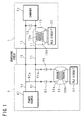
- Fig. 1 is a circuit diagram showing a configuration of a power line communication system according to the present invention.
- description will be given of an example of a configuration in which when a charging station (feeding device) 5 is connected to an electric vehicle (vehicle) 1 via a charging cable in order to charge a battery (not shown) of the electric vehicle 1, information such as charge control, user authentication, or accounting management is transmitted and received between the charging station 5 and the electric vehicle 1, through power line communication using the charging cable.
- the charging cable which connects the electric vehicle 1 to the charging station 5 includes: two power lines (hereinafter, simply referred to as AC lines) 71 and 72 to which an AC voltage is applied; and a grounding wire (not shown) connected to a ground potential.
- AC lines power lines
- grounding wire not shown
- a three-wire AC voltage using the two AC lines 71 and 72 and the one grounding wire is supplied from the charging station 5 to the electric vehicle 1.
- the charging station 5 includes: two internal power supply wires (hereinafter, simply referred to as AC lines) 51 and 52 to which an AC voltage is applied from a power source; and a grounding wire (not shown), the AC lines 51 and 52 and the grounding wire being respectively connected to the AC lines 71 and 72 and the grounding wire of the charging cable.
- the AC lines 51 and 52 are connected to a power source 61 of the charging station 5 and guide the AC power outputted by the power source 61 to the charging cable.
- branch lines 51a and 52a are connected, respectively, between the power source 61 and a terminal or the like to which the charging cable is connected, whereby the AC lines 51 and 52 are respectively branched.
- terminals on one side of capacitors 56 and 57 are connected, respectively.
- a primary coil 55a of a coupling transformer (electromagnetic induction type signal converter) 55 is connected to terminals on the other side of the capacitors 56 and 57. That is, the branch line 51a, the capacitor 56, the primary coil 55a of the coupling transformer 55, the capacitor 57, and the branch line 52a are connected in series in this order between the two AC lines 51 and 52.
- a secondary coil 55b of the coupling transformer 55 is connected to a power line communication circuit (hereinafter referred to as PLC (Power Line Communication) circuit) 62.
- PLC Power Line Communication
- the power line communication device installed in the charging station 5 includes: a signal superimposition/separation section composed of the capacitors 56 and 57 and the coupling transformer 55; and the PLC circuit 62 connected to the secondary coil 55b of the coupling transformer 55.
- the PLC circuit 62 can perform receiving processing by separating a signal superimposed on the AC lines 51 and 52 by means of the signal superimposition/separation section, and can perform transmitting processing by superimposing a signal on the AC lines 51 and 52 by means of the signal superimposition/separation section.
- the electric vehicle 1 includes two internal power supply wires (hereinafter, simply referred to as AC lines) 11 and 12 which are respectively connected to the AC lines 71 and 72 of the charging cable and which guide the power from the charging station 5 and the charging cable to a charger 21 in the electric vehicle 1. Further, in the electric vehicle, a capacitor 16 is connected to and between the two AC lines 11 and 12, and in the one AC line 11, a primary coil 15a of a coupling transformer (electromagnetic induction type signal converter) 15 is interposed between a connection point of the charging cable and a connection point of the capacitor 16. A secondary coil 15b of the coupling transformer 15 is connected to a PLC circuit 22 in the electric vehicle 1. Although the capacitor 16 between the AC lines 11 and 12 forms a filter circuit, in a case where a similar capacitor is installed in the charger 21, this capacitor may be used in common.
- AC lines internal power supply wires
- the power line communication device installed in the electric vehicle 1 includes: a signal superimposition/separation section composed of the coupling transformer 15 and the capacitor 16; and the PLC circuit 22 connected to the secondary coil 15b of the coupling transformer 15.
- the PLC circuit 22 can perform receiving processing by separating a signal superimposed on the AC lines 11 and 12 by means of the signal superimposition/separation section, and can perform transmitting processing by superimposing a signal on the AC lines 11 and 12 by means of the signal superimposition/separation section.
- two power supply paths are formed: an energizing path in which the AC line 51 of the charging station 5, the AC line 71 of the charging cable, and the AC line 11 of the electric vehicle 1, in the middle of which the primary coil 15a of the coupling transformer 15 is inserted, are connected; and an energizing path in which the AC line 52 of the charging station 5, the AC line 72 of the charging cable, and the AC line 12 of the electric vehicle 1 are connected.
- a closed current loop circuit is formed by the above two power supply paths, and the capacitor 16 connected to and between the AC lines 11 and 12 of the electric vehicle 1, the capacitors 56 and 57 and the primary coil 55a of the coupling transformer 55 connected between the AC line 51 and 52 of the charging station 5.
- the coupling transformers 15 and 55 arranged in this loop, whereby power line communication can be performed between the charging station 5 and the electric vehicle 1.
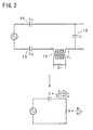
- FIG. 2 and Fig. 3 are schematic diagram for explaining a method for determining constants for circuit elements included in the power line communication system.
- Fig. 2 shows a circuit configuration in a case where the electric vehicle 1 is assumed as the receiving side in the power line communication, and its equivalent circuit.
- Fig. 3 shows a circuit configuration in a case where the charging station 5 is assumed as the receiving side in the power line communication, and its equivalent circuit.
- Fig. 2 and Fig. 3 shows a circuit configuration in a case where the charging station 5 is assumed as the receiving side in the power line communication, and its equivalent circuit.
- the capacitance of the capacitor 16 of the electric vehicle 1 is defined as C 1
- the resistance value of the input resistance of the PLC circuit 22 is defined as R 1
- the capacitance of each of the capacitors 56 of the charging station 5 is defined as C 2
- the resistance value of the input resistance of the PLC circuit 62 is defined as R 2 .
- the resistance value of the output resistance of the transmitting side circuit is sufficiently small compared with that of the input resistance of the receiving side circuit, and thus, is not taken into consideration in Fig. 2 and Fig. 3 .
- the reception frequency bands in the electric vehicle 1 and the charging station 5 are shifted from each other. This may result in receiving noise that should have been blocked, or blocking a signal that should have been received.
- the PLC circuit 62 of the charging station 5 performs power line communication by using the signal superimposition/separation section in which the capacitor 56, the coupling transformer 55, and the capacitor 57 are connected to the branch lines 51a and 52a branched from the two AC lines 51 and 52, and the PLC circuit 22 of the electric vehicle 1 performs power line communication by using the signal superimposition/separation section in which the coupling transformer 15 is inserted in the one AC line 11 and the capacitor 16 is connected to and between the two AC lines 11 and 12. Accordingly, power line communication devices having different configurations from each other can be installed in the charging station 5 and the electric vehicle 1, respectively.
- a closed loop circuit is formed that is composed of the AC line 51, the branch line 51a, the capacitor 56, the primary coil 55a of the coupling transformer 55, the capacitor 57, the branch line 52a, the AC line 52, the AC line 72, the AC line 12, the capacitor 16, the primary coil 15a of the coupling transformer 15, the AC line 11, and the AC line 71. Accordingly, power line communication can be performed between the charging station 5 and the electric vehicle 1.
- the AC lines 11 and 12 need not be branched. Thus, it is not necessary to secure space, in the electric vehicle 1, for arranging the branching portions and the branch lines of the AC lines 11 and 12. Therefore, compared with the power line communication device of the charging station 5, the power line communication device of the electric vehicle 1 can realize downsizing and space-saving.
- power line communication devices having different configurations from each other can perform power line communication in substantially the same communication frequency band. Accordingly, it is possible to prevent occurrence of a problem such as receiving noise that should have been blocked or blocking a signal that should have been received, and the like.
- the charging station 5 is provided with the power line communication device in which the coupling transformer 55 and the capacitors 56 and 57 are connected to the branch lines 51a and 52a branched from the AC lines 51 and 52, and the electric vehicle 1 is provided with the power line communication device in which the coupling transformer 15 is inserted in the one AC line 11 and the capacitor 16 is connected to and between the AC lines 11 and 12.
- the present invention is not limited thereto. The above configurations may be reversed.
- the electric vehicle 1 may be provided with a power line communication device in which a coupling transformer and capacitors are connected to branch lines branched from the AC lines 11 and 12, and the charging station may be provided with a power line communication device in which a coupling transformer is inserted in the one AC line 51 and a capacitor is connected to and between the AC lines 51 and 52.
- the electric vehicle 1 has been described as an example of a vehicle provided with a power line communication function, the present invention is not limited thereto.
- a vehicle may be another vehicle having a function of charging a battery from outside, such as a plug-in hybrid vehicle.
- the charging station 5 has been described as an example of a feeding device provided with a power line communication function, the present invention is not limited thereto.
- a feeding device may be another device having a function of feeding a vehicle via a charging cable.
- a power line communication device may be provided on a switchboard or the like of the house.
- a circuit that performs power line communication may be installed in a charging cable.
- the configuration of the power line communication system according to the present invention application thereof is not limited to power line communication performed when charging the electric vehicle 1 or the like.
- the configuration of the power line communication system according to the present invention can be applied to other various communication systems in which power line communication is performed (e.g., systems in which personal computers, portable electronic apparatuses, AV apparatuses, and the like perform power line communication in homes or offices).
- a first device in which a signal superimposition/separation section having an electromagnetic induction type signal converter such as a coupling transformer is connected to two branch lines branched from two power lines, and a second device in which a signal superimposition/separation section having a coupling transformer or the like is inserted in series in one of the power lines perform signal processing such as superimposition of a signal on the power lines and separation of a signal superimposed thereon, by using the signal superimposition/separation sections.
- signal processing such as superimposition of a signal on the power lines and separation of a signal superimposed thereon
- the second device which facilitates downsizing and space-saving.
- the conventional-type first device since power line communication devices having different configurations from each other can perform power line communication with each other, it is possible to select an optimum configuration for an apparatus to be provided with a power line communication function.
Landscapes
- Engineering & Computer Science (AREA)
- Power Engineering (AREA)
- Computer Networks & Wireless Communication (AREA)
- Signal Processing (AREA)
- Transportation (AREA)
- Mechanical Engineering (AREA)
- Cable Transmission Systems, Equalization Of Radio And Reduction Of Echo (AREA)
- Electric Propulsion And Braking For Vehicles (AREA)
- Hybrid Electric Vehicles (AREA)
- Charge And Discharge Circuits For Batteries Or The Like (AREA)
Abstract
Description
- The present invention relates to power line communication systems in which two devices perform power line communication with each other via power lines, and relates to power line communication systems suitable, for example, for a case where a vehicle, such as an electric vehicle or a plug-in hybrid vehicle, whose battery can be charged by external feeding, and an external feeding device perform power line communication with each other via a charging cable.
- In recent years, there are beginning to prevail electric vehicles and hybrid vehicles which include devices such as motors and batteries and which travel by driving the motors, using power accumulated in the batteries. Electric vehicles need to have their batteries charged by external feeding devices, and even in the case of hybrid vehicles, there are plug-in hybrid vehicles that allow their batteries to be charged by external feeding devices. In a vehicle whose battery is charged from outside, a plug of a charging cable connected to an external feeding device is coupled to a connector device of a charging port provided in the vehicle, and power is supplied from the feeding device to the battery of the vehicle via the charging cable, whereby the battery is charged.
- On the other hand, in the case of charging a battery of a vehicle by a feeding device, a communication function is required that allows transmission and reception of information for controlling the charge and information for managing the amount of charge, accounting, etc. between the vehicle and the feeding device. For communication between the vehicle and the feeding device, it is conceivable to use power line communication via a charging cable.
-
Patent Literature 1 proposes a power line carrier device configured such that data of a frame length of Ethernet is converted into fixed packets shorter than this frame length, to be converted into power line carrier signals using each packet as a unit, thereby performing communication using a power line, and when a communication error occurs, packets are transmitted again. Accordingly, the power line carrier device has an enhanced throughput. - Conventional power line communication devices typically employ a configuration in which two power lines are each branched to have a branch line, and an electromagnetic induction type signal converter (a circuit element such as a coupling transformer) which superimposes and separates a signal on and from the power lines is connected to the branch lines (that is, a coupling transformer or the like is connected to and between the two power lines). The power line carrier device described in
Patent Literature 1 has a similar configuration to the above. -
- [PTL 1] Japanese Laid-Open Patent Publication No.
2002-261663 - However, in the configuration of the conventional power line communication device described above, the two power lines need to be branched. Therefore, space for arranging the branching portions of the two power lines and the branched two branch lines is necessary. Since a large number of electronic apparatuses are installed in a vehicle such as an electric vehicle, space for arranging apparatuses in the vehicle is limited. Therefore, when installing a power line communication device having a conventional configuration in a vehicle, it is not easy to secure space for arranging branching portions and branch lines of power lines, and thus downsizing of and saving space for the on-vehicle power line communication device are desired.
- On the other hand, with respect to a feeding device, which is installed outside a vehicle such as in a charging station or near a private parking space, space for arranging apparatuses is not so much limited as in the case of a vehicle. Thus, there are cases where it is more preferable to employ a power line communication device having a conventional configuration with proven performance, than to prioritize downsizing of or saving space for the power line communication device. Further, in a charging station considered to be used by various types of vehicles, it may be preferable to employ a widely-adopted power line communication device having a conventional configuration.
- Therefore, an object of the present invention is to provide a power line communication system which allows power line communication to be performed at the time of coexistence of a power line communication device having a conventional configuration with proven performance and a power line communication device having another configuration for realizing downsizing and space-saving.
- A power line communication system according to the present invention is a power line communication system in which a first device and a second device connected to each other with two power lines perform communication via the power lines, the first device including: a signal superimposition/separation section which is connected to two branch lines respectively branched from the two power lines and which superimposes a signal on the power lines and separates a signal superimposed on the power lines; and a power line communication section which performs power line communication via the signal superimposition/separation section, and the second device including: a signal superimposition/separation section which is inserted in one of the power lines and which superimposes a signal on the power line and separates a signal superimposed on the power line; and a power line communication section which performs power line communication via the signal superimposition/separation section.
- Further, in the power line communication system according to the present invention, the signal superimposition/separation section of the first device includes: two capacitors respectively connected to the two branch lines; and an electromagnetic induction type signal converter whose primary coil is connected to the two capacitors and whose secondary coil is connected to the power line communication section, and the signal superimposition/separation section of the second device includes: an electromagnetic induction type signal converter whose primary coil is interposed in the one of the power lines and whose secondary coil is connected to the power line communication section; and a capacitor connected to and between the two power lines.
- Further, in the power line communication system according to the present invention, a ratio n1 of the number of turns of the secondary coil of the signal converter of the first device to the number of turns of the primary coil thereof, an input resistance value R1 of the power line communication section of the first device, a ratio n2 of the number of turns of the secondary coil of the signal converter of the second device to the number of turns of the primary coil thereof, and an input resistance value R2 of the power line communication section of the second device satisfy a condition of R1/(n1)2 = R2/(n2)2.
- Further, a power line communication system according to the present invention is a power line communication system in which, in a case where a feeding device and a vehicle are connected to each other via a charging cable including two power lines, a first device provided in the feeding device and a second device installed in the vehicle perform communication with each other via the power lines, the first device including: a signal superimposition/separation section which is connected to two branch lines respectively branched from the two power lines and which superimposes a signal on the power lines and separates a signal superimposed on the power lines; and a power line communication section which performs power line communication via the signal superimposition/separation section, and the second device including: a signal superimposition/separation section which is inserted in one of the power lines and which superimposes a signal on the power line and separates a signal superimposed on the power line; and a power line communication section which performs power line communication via the signal superimposition/separation section.
- The present invention is configured such that the first device and the second device connected to each other with two power lines perform power line communication. The first device employs a configuration of a conventional power line communication device, and the second device employs a configuration different from this. That is, in the first device, a signal superimposition/separation section having an electromagnetic induction type signal converter (such as coupling transformer) is connected to two branch lines branched from two power lines. By using this signal superimposition/separation section, the first device performs signal processing such as superimposition of a signal on the power lines and separation of a signal superimposed thereon. In contrast, in the second device, a signal superimposition/separation section having a coupling transformer or the like is inserted in one power line. By using this signal superimposition/separation section, the second device performs signal processing such as superimposition of a signal on the power line and separation of a signal superimposed thereon.
- Since the second device has the above configuration, which is different from that of the first device, the second device can perform power line communication. Since it is not necessary to branch the power lines in the second device, space for arranging branching portions and branch lines that have been branched from the power lines is not necessary. Therefore, compared with a power line communication device having a conventional configuration, the second device can realize downsizing and space-saving.
- Further, according to the present invention, in the first device, capacitors are connected to two branch lines respectively branched from two power lines, and a primary coil of a coupling transformer is connected to the two capacitors (that is, a branch line, a capacitor, the primary coil, a capacitor, and a branch line are connected in series in this order), to form a signal superimposition/separation section, and a secondary coil of the coupling transformer is connected to a power line communication section. Further, in the second device, the primary coil of a coupling transformer is interposed in one power line and a power line communication section is connected to the secondary coil thereof, and a capacitor is connected to and between the two power lines, to form a signal superimposition/separation section.
- In the above configuration, a closed loop circuit is formed, such as: one power line, one branch line, a capacitor of the first device, the primary coil of the first device, a capacitor of the first device, the other branch line, the other power line, the primary coil of the second device, a capacitor of the second device, one power line, and the like, and thus, power line communication via the power lines can be performed.
- Further, according to the present invention, in a case where the ratio of the number of turns of the secondary coil of the coupling transformer of the first device to the number of turns of the primary coil thereof is defined as n1, the input resistance value of the power line communication section of the first device is defined as R1, the ratio of the number of turns of the secondary coil of the coupling transformer of the second device to the number of turns of the primary coil thereof is defined as n2, and the input resistance value of the power line communication section of the second device is defined as R2, constants of the circuit elements of the first device and the second device are set so as to satisfy the condition of

- Accordingly, the first device and the second device can perform power line communication in substantially the same communication frequency band, and thus, it is possible to prevent communication from being blocked due to interference of unexpected noise or the like.
- Further, according to the present invention, in a system configuration in which a feeding device and a vehicle are connected to each other via a charging cable and the feeding device supplies power to the vehicle via the charging cable, the feeding device and the vehicle perform power line communication with each other, with the first device provided in the feeding device and the second device provided in the vehicle. With respect to the second device, the power lines need not be branched, and thus, downsizing and space-saving can be realized. Thus, it is suitable for the second device to be installed in a vehicle where space for arranging apparatuses is limited.
-
- [
Fig. 1] Fig. 1 is a circuit diagram showing a configuration of a power line communication system according to the present invention. - [
Fig. 2] Fig. 2 is a schematic diagram for explaining a method for determining constants for circuit elements included in the power line communication system. - [
Fig. 3] Fig. 3 is a schematic diagram for explaining a method for determining constants for circuit elements included in the power line communication system. - Hereinafter, the present invention will be described specifically, with reference to the drawings illustrating embodiments thereof.
Fig. 1 is a circuit diagram showing a configuration of a power line communication system according to the present invention. In the present embodiment, description will be given of an example of a configuration in which when a charging station (feeding device) 5 is connected to an electric vehicle (vehicle) 1 via a charging cable in order to charge a battery (not shown) of theelectric vehicle 1, information such as charge control, user authentication, or accounting management is transmitted and received between thecharging station 5 and theelectric vehicle 1, through power line communication using the charging cable. - The charging cable which connects the
electric vehicle 1 to thecharging station 5 includes: two power lines (hereinafter, simply referred to as AC lines) 71 and 72 to which an AC voltage is applied; and a grounding wire (not shown) connected to a ground potential. In the present embodiment, a three-wire AC voltage using the twoAC lines charging station 5 to theelectric vehicle 1. - The
charging station 5 includes: two internal power supply wires (hereinafter, simply referred to as AC lines) 51 and 52 to which an AC voltage is applied from a power source; and a grounding wire (not shown), theAC lines AC lines AC lines power source 61 of thecharging station 5 and guide the AC power outputted by thepower source 61 to the charging cable. - To the
AC lines branch lines 51a and 52a are connected, respectively, between thepower source 61 and a terminal or the like to which the charging cable is connected, whereby theAC lines branch lines 51a and 52a, terminals on one side ofcapacitors capacitors branch line 51a, thecapacitor 56, the primary coil 55a of thecoupling transformer 55, thecapacitor 57, and the branch line 52a are connected in series in this order between the twoAC lines secondary coil 55b of thecoupling transformer 55 is connected to a power line communication circuit (hereinafter referred to as PLC (Power Line Communication) circuit) 62. - That is, the power line communication device installed in the
charging station 5 includes: a signal superimposition/separation section composed of thecapacitors coupling transformer 55; and thePLC circuit 62 connected to thesecondary coil 55b of thecoupling transformer 55. ThePLC circuit 62 can perform receiving processing by separating a signal superimposed on theAC lines AC lines - The
electric vehicle 1 includes two internal power supply wires (hereinafter, simply referred to as AC lines) 11 and 12 which are respectively connected to theAC lines charging station 5 and the charging cable to acharger 21 in theelectric vehicle 1. Further, in the electric vehicle, acapacitor 16 is connected to and between the twoAC lines AC line 11, a primary coil 15a of a coupling transformer (electromagnetic induction type signal converter) 15 is interposed between a connection point of the charging cable and a connection point of thecapacitor 16. Asecondary coil 15b of thecoupling transformer 15 is connected to aPLC circuit 22 in theelectric vehicle 1. Although thecapacitor 16 between the AC lines 11 and 12 forms a filter circuit, in a case where a similar capacitor is installed in thecharger 21, this capacitor may be used in common. - That is, the power line communication device installed in the
electric vehicle 1 includes: a signal superimposition/separation section composed of thecoupling transformer 15 and thecapacitor 16; and thePLC circuit 22 connected to thesecondary coil 15b of thecoupling transformer 15. ThePLC circuit 22 can perform receiving processing by separating a signal superimposed on the AC lines 11 and 12 by means of the signal superimposition/separation section, and can perform transmitting processing by superimposing a signal on the AC lines 11 and 12 by means of the signal superimposition/separation section. - By connecting the charging
station 5 and theelectric vehicle 1 to each other with the charging cable, two power supply paths are formed: an energizing path in which theAC line 51 of the chargingstation 5, theAC line 71 of the charging cable, and theAC line 11 of theelectric vehicle 1, in the middle of which the primary coil 15a of thecoupling transformer 15 is inserted, are connected; and an energizing path in which theAC line 52 of the chargingstation 5, theAC line 72 of the charging cable, and theAC line 12 of theelectric vehicle 1 are connected. In a state where the chargingstation 5 and theelectric vehicle 1 are connected to each other with the charging cable, a closed current loop circuit is formed by the above two power supply paths, and thecapacitor 16 connected to and between the AC lines 11 and 12 of theelectric vehicle 1, thecapacitors coupling transformer 55 connected between theAC line station 5. Thus, it is possible to superimpose a signal on the AC lines 11 and 12 and the AC lines 51 and 52 and to extract a signal superimposed thereon by means of thecoupling transformers station 5 and theelectric vehicle 1. - Each of
Fig. 2 andFig. 3 is a schematic diagram for explaining a method for determining constants for circuit elements included in the power line communication system.Fig. 2 shows a circuit configuration in a case where theelectric vehicle 1 is assumed as the receiving side in the power line communication, and its equivalent circuit.Fig. 3 shows a circuit configuration in a case where the chargingstation 5 is assumed as the receiving side in the power line communication, and its equivalent circuit. InFig. 2 andFig. 3 , the capacitance of thecapacitor 16 of theelectric vehicle 1 is defined as C1, the ratio between the number of turns of the primary coil 15a and that of thesecondary coil 15b of thecoupling transformer 15 is defined as primary coil : secondary coil = 1 : n1, and the resistance value of the input resistance of thePLC circuit 22 is defined as R1, the capacitance of each of thecapacitors 56 of the chargingstation 5 is defined as C2, the ratio between the number of turns of the primary coil 55a and that of thesecondary coil 55b of thecoupling transformer 55 is defined as primary coil : secondary coil = 1 : n2, and the resistance value of the input resistance of thePLC circuit 62 is defined as R2. The resistance value of the output resistance of the transmitting side circuit is sufficiently small compared with that of the input resistance of the receiving side circuit, and thus, is not taken into consideration inFig. 2 andFig. 3 . - In a case where the
electric vehicle 1 is assumed as the receiving side, when the transmitting side circuit on the chargingstation 5 side is defined as a source of a signal, the circuit regarding reception as shown in the upper part ofFig. 2 is obtained, that is, a closed loop circuit is obtained in which, with respect to the source, thecapacitor 56, thecapacitor 16, thecoupling transformer 15, and thecapacitor 56 are connected in this order. If converting this circuit into its equivalent circuit composed only of a resistance and a capacitor, the circuit shown in the lower part ofFig. 2 is obtained. In this equivalent circuit, the resistance value R of the resistance satisfies R = (R1/(n1)2), and the capacitance C of the capacitor satisfies C = C1C2/(2C1+C2). - Further, in a case where the charging
station 5 is assumed as the receiving side, when the transmitting side circuit on theelectric vehicle 1 side is defined as a source of a signal, the circuit regarding reception as shown in the upper part ofFig. 3 is obtained, that is, a closed loop circuit is obtained in which, with respect to the source, thecapacitor 16, thecapacitor 56, thecoupling transformer 55, and thecapacitor 56 are connected in this order. If converting this circuit into its equivalent circuit composed only of a resistance and a capacitor, the circuit shown in the lower part ofFig. 3 is obtained. In this equivalent circuit, the resistance value R of the resistance satisfies R = (R2/(n2)2), and the capacitance C of the capacitor satisfies C = C1C2/(2C1+C2). - Here, in order to allow the
electric vehicle 1 and the chargingstation 5 to transmit and receive signals in the same frequency band to and from each other, since the capacitance values C are equal to each other in the equivalent circuits shown in the lower part ofFig. 2 and the lower part ofFig. 3 , the resistance values R need to be equal to each other. That is, the following (expression 1) needs to be satisfied.
- When this conditional expression is not satisfied, the reception frequency bands in the
electric vehicle 1 and the chargingstation 5 are shifted from each other. This may result in receiving noise that should have been blocked, or blocking a signal that should have been received. - In the power line communication system having the above configuration, the
PLC circuit 62 of the chargingstation 5 performs power line communication by using the signal superimposition/separation section in which thecapacitor 56, thecoupling transformer 55, and thecapacitor 57 are connected to thebranch lines 51a and 52a branched from the twoAC lines PLC circuit 22 of theelectric vehicle 1 performs power line communication by using the signal superimposition/separation section in which thecoupling transformer 15 is inserted in the oneAC line 11 and thecapacitor 16 is connected to and between the twoAC lines station 5 and theelectric vehicle 1, respectively. In this configuration, in a case where the chargingstation 5 and theelectric vehicle 1 are connected to each other with the charging cable, a closed loop circuit is formed that is composed of theAC line 51, thebranch line 51a, thecapacitor 56, the primary coil 55a of thecoupling transformer 55, thecapacitor 57, the branch line 52a, theAC line 52, theAC line 72, theAC line 12, thecapacitor 16, the primary coil 15a of thecoupling transformer 15, theAC line 11, and theAC line 71. Accordingly, power line communication can be performed between the chargingstation 5 and theelectric vehicle 1. - In the above-described power line communication device installed in the
electric vehicle 1, the AC lines 11 and 12 need not be branched. Thus, it is not necessary to secure space, in theelectric vehicle 1, for arranging the branching portions and the branch lines of the AC lines 11 and 12. Therefore, compared with the power line communication device of the chargingstation 5, the power line communication device of theelectric vehicle 1 can realize downsizing and space-saving. - Further, by setting the input resistance values R1 and R2 of the
PLC circuits coupling transformers - In the present embodiment, the charging
station 5 is provided with the power line communication device in which thecoupling transformer 55 and thecapacitors branch lines 51a and 52a branched from the AC lines 51 and 52, and theelectric vehicle 1 is provided with the power line communication device in which thecoupling transformer 15 is inserted in the oneAC line 11 and thecapacitor 16 is connected to and between the AC lines 11 and 12. However, the present invention is not limited thereto. The above configurations may be reversed. That is, theelectric vehicle 1 may be provided with a power line communication device in which a coupling transformer and capacitors are connected to branch lines branched from the AC lines 11 and 12, and the charging station may be provided with a power line communication device in which a coupling transformer is inserted in the oneAC line 51 and a capacitor is connected to and between the AC lines 51 and 52. - Although the
electric vehicle 1 has been described as an example of a vehicle provided with a power line communication function, the present invention is not limited thereto. Such a vehicle may be another vehicle having a function of charging a battery from outside, such as a plug-in hybrid vehicle. Further, although the chargingstation 5 has been described as an example of a feeding device provided with a power line communication function, the present invention is not limited thereto. Such a feeding device may be another device having a function of feeding a vehicle via a charging cable. For example, in a case where a user plugs a charging cable into an outlet in the user's house and charges a vehicle, a power line communication device may be provided on a switchboard or the like of the house. Furthermore, a circuit that performs power line communication may be installed in a charging cable. - Furthermore, with respect to the configuration of the power line communication system according to the present invention, application thereof is not limited to power line communication performed when charging the
electric vehicle 1 or the like. The configuration of the power line communication system according to the present invention can be applied to other various communication systems in which power line communication is performed (e.g., systems in which personal computers, portable electronic apparatuses, AV apparatuses, and the like perform power line communication in homes or offices). - As described above, according to the power line communication system of the present embodiment, a first device in which a signal superimposition/separation section having an electromagnetic induction type signal converter such as a coupling transformer is connected to two branch lines branched from two power lines, and a second device in which a signal superimposition/separation section having a coupling transformer or the like is inserted in series in one of the power lines perform signal processing such as superimposition of a signal on the power lines and separation of a signal superimposed thereon, by using the signal superimposition/separation sections. Thus, two devices having different configurations from each other can perform power line communication with each other via the power lines. Accordingly, for example, in a case where a power line communication function is provided in a vehicle or the like where installation space is limited, it is possible to employ the second device which facilitates downsizing and space-saving. Alternatively, for example, in a case where there is enough installation space such as in a feeding device and versatility and proven performance is prioritized, it is possible to employ the conventional-type first device. That is, since power line communication devices having different configurations from each other can perform power line communication with each other, it is possible to select an optimum configuration for an apparatus to be provided with a power line communication function.
-
- 1
- electric vehicle (second device, feeding device)
- 5
- charging station (first device, vehicle)
- 11, 12
- AC line (power line)
- 15
- coupling transformer (signal superimposition/separation section, signal converter)
- 15a
- primary coil
- 15b
- secondary coil
- 16
- capacitor (signal superimposition/separation section)
- 21
- charger
- 22
- PLC circuit (power line communication section)
- 51, 52
- AC line (power line)
- 51a, 52a
- branch line
- 55
- coupling transformer (signal superimposition/separation section, signal converter)
- 55a
- primary coil
- 55b
- secondary coil
- 56, 57
- capacitor (signal superimposition/separation section)
- 61
- power source
- 62
- PLC circuit (power line communication section)
- 71, 72
- AC line (power line)
Claims (4)
- A power line communication system in which a first device and a second device connected to each other with two power lines perform communication via the power lines,
the first device comprising:a signal superimposition/separation section which is connected to two branch lines respectively branched from the two power lines and which superimposes a signal on the power lines and separates a signal superimposed on the power lines; anda power line communication section which performs power line communication via the signal superimposition/separation section, andthe second device comprising:a signal superimposition/separation section which is inserted in one of the power lines and which superimposes a signal on the power line and separates a signal superimposed on the power line; anda power line communication section which performs power line communication via the signal superimposition/separation section. - The power line communication system according to claim 1, wherein
the signal superimposition/separation section of the first device includes:two capacitors respectively connected to the two branch lines; andan electromagnetic induction type signal converter whose primary coil is connected to the two capacitors and whose secondary coil is connected to the power line communication section, andthe signal superimposition/separation section of the second device includes:an electromagnetic induction type signal converter whose primary coil is interposed in the one of the power lines and whose secondary coil is connected to the power line communication section; anda capacitor connected to and between the two power lines. - The power line communication system according to claim 2, wherein
a ratio n1 of the number of turns of the secondary coil of the signal converter of the first device to the number of turns of the primary coil thereof, an input resistance value R1 of the power line communication section of the first device, a ratio n2 of the number of turns of the secondary coil of the signal converter of the second device to the number of turns of the primary coil thereof, and an input resistance value R2 of the power line communication section of the second device satisfy a condition of
- A power line communication system in which, in a case where a feeding device and a vehicle are connected to each other via a charging cable including two power lines, a first device provided in the feeding device and a second device installed in the vehicle perform communication with each other via the power lines,
the first device comprising:a signal superimposition/separation section which is connected to two branch lines respectively branched from the two power lines and which superimposes a signal on the power lines and separates a signal superimposed on the power lines; anda power line communication section which performs power line communication via the signal superimposition/separation section, andthe second device comprising:a signal superimposition/separation section which is inserted in one of the power lines and which superimposes a signal on the power line and separates a signal superimposed on the power line; anda power line communication section which performs power line communication via the signal superimposition/separation section.
Applications Claiming Priority (2)
| Application Number | Priority Date | Filing Date | Title |
|---|---|---|---|
| JP2011037438A JP5746517B2 (en) | 2011-02-23 | 2011-02-23 | Power line communication system |
| PCT/JP2012/052271 WO2012114838A1 (en) | 2011-02-23 | 2012-02-01 | Power line communication system |
Publications (3)
| Publication Number | Publication Date |
|---|---|
| EP2680454A1 true EP2680454A1 (en) | 2014-01-01 |
| EP2680454A4 EP2680454A4 (en) | 2015-01-21 |
| EP2680454B1 EP2680454B1 (en) | 2016-05-18 |
Family
ID=46720626
Family Applications (1)
| Application Number | Title | Priority Date | Filing Date |
|---|---|---|---|
| EP12749318.7A Not-in-force EP2680454B1 (en) | 2011-02-23 | 2012-02-01 | Power line communication system |
Country Status (5)
| Country | Link |
|---|---|
| US (1) | US9337897B2 (en) |
| EP (1) | EP2680454B1 (en) |
| JP (1) | JP5746517B2 (en) |
| CN (1) | CN103392298B (en) |
| WO (1) | WO2012114838A1 (en) |
Families Citing this family (8)
| Publication number | Priority date | Publication date | Assignee | Title |
|---|---|---|---|---|
| US9240821B2 (en) | 2011-07-13 | 2016-01-19 | Sumitomo Electric Industries, Ltd. | Communication system |
| CN103368015B (en) * | 2012-04-10 | 2016-08-17 | 泰科电子(上海)有限公司 | Intelligent connector and bus control unit |
| WO2016191662A1 (en) | 2015-05-27 | 2016-12-01 | Intelligent Technologies International, Inc. | Vehicle wire harness |
| EP4156532B1 (en) | 2020-06-29 | 2025-12-10 | Google LLC | Enhanced edge detect power line communication |
| CN111934720B (en) * | 2020-08-28 | 2021-05-28 | 杭州华罡智能科技有限公司 | Cross-signal-source carrier transmission circuit |
| EP4283878A4 (en) | 2021-01-20 | 2024-07-03 | Panasonic Intellectual Property Management Co., Ltd. | COMMUNICATION DEVICE |
| CN112865785A (en) * | 2021-01-22 | 2021-05-28 | 天津智模科技有限公司 | Digital signal isolator |
| CN115042644B (en) * | 2022-05-24 | 2026-04-14 | 中电海康集团有限公司 | Electric vehicle charging system, method and device |
Family Cites Families (13)
| Publication number | Priority date | Publication date | Assignee | Title |
|---|---|---|---|---|
| JPS5028621B2 (en) | 1972-06-23 | 1975-09-17 | ||
| JPS5028621Y2 (en) * | 1972-09-19 | 1975-08-23 | ||
| JPS5028621U (en) * | 1973-07-12 | 1975-04-02 | ||
| US4668934A (en) * | 1984-10-22 | 1987-05-26 | Westinghouse Electric Corp. | Receiver apparatus for three-phase power line carrier communications |
| US4667194A (en) * | 1984-11-02 | 1987-05-19 | Raychem Corporation | Monitoring system for use with elongate heater units |
| JPS61136327A (en) * | 1984-12-06 | 1986-06-24 | Nec Corp | Signal coupling system for low voltage distribution line communication equipment |
| JP3112226B2 (en) | 1993-12-27 | 2000-11-27 | 矢崎総業株式会社 | Charging connector for electric vehicles |
| JP2002261663A (en) | 2001-03-06 | 2002-09-13 | Hitachi Ltd | Power line carrier device and power line carrier communication method |
| JP2006261940A (en) | 2005-03-16 | 2006-09-28 | Smk Corp | Power line communication coupling circuit |
| JP5285842B2 (en) * | 2006-04-13 | 2013-09-11 | パナソニック株式会社 | Integrated circuit mounting board and power line communication device |
| WO2010100951A1 (en) * | 2009-03-06 | 2010-09-10 | パナソニック株式会社 | Power supply device |
| JP5278954B2 (en) * | 2009-03-24 | 2013-09-04 | シャープ株式会社 | Power line communication apparatus and communication method in power line communication apparatus |
| JP2011015530A (en) * | 2009-07-02 | 2011-01-20 | Panasonic Corp | Leakage detection power supply controller |
-
2011
- 2011-02-23 JP JP2011037438A patent/JP5746517B2/en not_active Expired - Fee Related
-
2012
- 2012-02-01 EP EP12749318.7A patent/EP2680454B1/en not_active Not-in-force
- 2012-02-01 US US14/001,421 patent/US9337897B2/en not_active Expired - Fee Related
- 2012-02-01 CN CN201280010323.8A patent/CN103392298B/en not_active Expired - Fee Related
- 2012-02-01 WO PCT/JP2012/052271 patent/WO2012114838A1/en not_active Ceased
Non-Patent Citations (2)
| Title |
|---|
| No further relevant documents disclosed * |
| See also references of WO2012114838A1 * |
Also Published As
| Publication number | Publication date |
|---|---|
| US20130328528A1 (en) | 2013-12-12 |
| EP2680454B1 (en) | 2016-05-18 |
| JP2012175562A (en) | 2012-09-10 |
| EP2680454A4 (en) | 2015-01-21 |
| JP5746517B2 (en) | 2015-07-08 |
| US9337897B2 (en) | 2016-05-10 |
| CN103392298B (en) | 2015-11-25 |
| WO2012114838A1 (en) | 2012-08-30 |
| CN103392298A (en) | 2013-11-13 |
Similar Documents
| Publication | Publication Date | Title |
|---|---|---|
| US9337897B2 (en) | Power line communication system | |
| US9174592B2 (en) | Power line communications system, power line communication device, and connector device | |
| EP2827508B1 (en) | Communication device and communication system | |
| EP2683089B1 (en) | Connector device, and power line communication device | |
| US9130659B2 (en) | Communication device and communication system | |
| EP2733860B1 (en) | Communication system | |
| EP2804269B1 (en) | Power reception connector and communication system | |
| EP2846435A1 (en) | Communication system, charge control apparatus, vehicle and feeding apparatus | |
| EP3220590B1 (en) | Communication system and communication device | |
| EP2824792B1 (en) | Power receiving connector, charging system, and communication system | |
| EP3220589B1 (en) | Communication system and connector | |
| WO2013094721A1 (en) | Feeding apparatus and communication method |
Legal Events
| Date | Code | Title | Description |
|---|---|---|---|
| PUAI | Public reference made under article 153(3) epc to a published international application that has entered the european phase |
Free format text: ORIGINAL CODE: 0009012 |
|
| 17P | Request for examination filed |
Effective date: 20130709 |
|
| AK | Designated contracting states |
Kind code of ref document: A1 Designated state(s): AL AT BE BG CH CY CZ DE DK EE ES FI FR GB GR HR HU IE IS IT LI LT LU LV MC MK MT NL NO PL PT RO RS SE SI SK SM TR |
|
| DAX | Request for extension of the european patent (deleted) | ||
| A4 | Supplementary search report drawn up and despatched |
Effective date: 20141219 |
|
| RIC1 | Information provided on ipc code assigned before grant |
Ipc: B60L 11/18 20060101ALI20141215BHEP Ipc: B60K 6/28 20071001ALI20141215BHEP Ipc: H04B 3/54 20060101AFI20141215BHEP |
|
| GRAP | Despatch of communication of intention to grant a patent |
Free format text: ORIGINAL CODE: EPIDOSNIGR1 |
|
| INTG | Intention to grant announced |
Effective date: 20151209 |
|
| GRAS | Grant fee paid |
Free format text: ORIGINAL CODE: EPIDOSNIGR3 |
|
| GRAA | (expected) grant |
Free format text: ORIGINAL CODE: 0009210 |
|
| AK | Designated contracting states |
Kind code of ref document: B1 Designated state(s): AL AT BE BG CH CY CZ DE DK EE ES FI FR GB GR HR HU IE IS IT LI LT LU LV MC MK MT NL NO PL PT RO RS SE SI SK SM TR |
|
| REG | Reference to a national code |
Ref country code: GB Ref legal event code: FG4D |
|
| REG | Reference to a national code |
Ref country code: CH Ref legal event code: EP |
|
| REG | Reference to a national code |
Ref country code: IE Ref legal event code: FG4D Ref country code: AT Ref legal event code: REF Ref document number: 801240 Country of ref document: AT Kind code of ref document: T Effective date: 20160615 |
|
| REG | Reference to a national code |
Ref country code: DE Ref legal event code: R096 Ref document number: 602012018617 Country of ref document: DE |
|
| REG | Reference to a national code |
Ref country code: NL Ref legal event code: MP Effective date: 20160518 |
|
| REG | Reference to a national code |
Ref country code: LT Ref legal event code: MG4D |
|
| PG25 | Lapsed in a contracting state [announced via postgrant information from national office to epo] |
Ref country code: NO Free format text: LAPSE BECAUSE OF FAILURE TO SUBMIT A TRANSLATION OF THE DESCRIPTION OR TO PAY THE FEE WITHIN THE PRESCRIBED TIME-LIMIT Effective date: 20160818 Ref country code: FI Free format text: LAPSE BECAUSE OF FAILURE TO SUBMIT A TRANSLATION OF THE DESCRIPTION OR TO PAY THE FEE WITHIN THE PRESCRIBED TIME-LIMIT Effective date: 20160518 Ref country code: LT Free format text: LAPSE BECAUSE OF FAILURE TO SUBMIT A TRANSLATION OF THE DESCRIPTION OR TO PAY THE FEE WITHIN THE PRESCRIBED TIME-LIMIT Effective date: 20160518 Ref country code: NL Free format text: LAPSE BECAUSE OF FAILURE TO SUBMIT A TRANSLATION OF THE DESCRIPTION OR TO PAY THE FEE WITHIN THE PRESCRIBED TIME-LIMIT Effective date: 20160518 |
|
| REG | Reference to a national code |
Ref country code: AT Ref legal event code: MK05 Ref document number: 801240 Country of ref document: AT Kind code of ref document: T Effective date: 20160518 |
|
| PG25 | Lapsed in a contracting state [announced via postgrant information from national office to epo] |
Ref country code: ES Free format text: LAPSE BECAUSE OF FAILURE TO SUBMIT A TRANSLATION OF THE DESCRIPTION OR TO PAY THE FEE WITHIN THE PRESCRIBED TIME-LIMIT Effective date: 20160518 Ref country code: RS Free format text: LAPSE BECAUSE OF FAILURE TO SUBMIT A TRANSLATION OF THE DESCRIPTION OR TO PAY THE FEE WITHIN THE PRESCRIBED TIME-LIMIT Effective date: 20160518 Ref country code: PT Free format text: LAPSE BECAUSE OF FAILURE TO SUBMIT A TRANSLATION OF THE DESCRIPTION OR TO PAY THE FEE WITHIN THE PRESCRIBED TIME-LIMIT Effective date: 20160919 Ref country code: GR Free format text: LAPSE BECAUSE OF FAILURE TO SUBMIT A TRANSLATION OF THE DESCRIPTION OR TO PAY THE FEE WITHIN THE PRESCRIBED TIME-LIMIT Effective date: 20160819 Ref country code: LV Free format text: LAPSE BECAUSE OF FAILURE TO SUBMIT A TRANSLATION OF THE DESCRIPTION OR TO PAY THE FEE WITHIN THE PRESCRIBED TIME-LIMIT Effective date: 20160518 Ref country code: SE Free format text: LAPSE BECAUSE OF FAILURE TO SUBMIT A TRANSLATION OF THE DESCRIPTION OR TO PAY THE FEE WITHIN THE PRESCRIBED TIME-LIMIT Effective date: 20160518 Ref country code: HR Free format text: LAPSE BECAUSE OF FAILURE TO SUBMIT A TRANSLATION OF THE DESCRIPTION OR TO PAY THE FEE WITHIN THE PRESCRIBED TIME-LIMIT Effective date: 20160518 |
|
| PG25 | Lapsed in a contracting state [announced via postgrant information from national office to epo] |
Ref country code: IT Free format text: LAPSE BECAUSE OF FAILURE TO SUBMIT A TRANSLATION OF THE DESCRIPTION OR TO PAY THE FEE WITHIN THE PRESCRIBED TIME-LIMIT Effective date: 20160518 |
|
| REG | Reference to a national code |
Ref country code: FR Ref legal event code: PLFP Year of fee payment: 6 |
|
| PG25 | Lapsed in a contracting state [announced via postgrant information from national office to epo] |
Ref country code: EE Free format text: LAPSE BECAUSE OF FAILURE TO SUBMIT A TRANSLATION OF THE DESCRIPTION OR TO PAY THE FEE WITHIN THE PRESCRIBED TIME-LIMIT Effective date: 20160518 Ref country code: DK Free format text: LAPSE BECAUSE OF FAILURE TO SUBMIT A TRANSLATION OF THE DESCRIPTION OR TO PAY THE FEE WITHIN THE PRESCRIBED TIME-LIMIT Effective date: 20160518 Ref country code: RO Free format text: LAPSE BECAUSE OF FAILURE TO SUBMIT A TRANSLATION OF THE DESCRIPTION OR TO PAY THE FEE WITHIN THE PRESCRIBED TIME-LIMIT Effective date: 20160518 Ref country code: CZ Free format text: LAPSE BECAUSE OF FAILURE TO SUBMIT A TRANSLATION OF THE DESCRIPTION OR TO PAY THE FEE WITHIN THE PRESCRIBED TIME-LIMIT Effective date: 20160518 Ref country code: SK Free format text: LAPSE BECAUSE OF FAILURE TO SUBMIT A TRANSLATION OF THE DESCRIPTION OR TO PAY THE FEE WITHIN THE PRESCRIBED TIME-LIMIT Effective date: 20160518 |
|
| REG | Reference to a national code |
Ref country code: DE Ref legal event code: R097 Ref document number: 602012018617 Country of ref document: DE |
|
| PG25 | Lapsed in a contracting state [announced via postgrant information from national office to epo] |
Ref country code: PL Free format text: LAPSE BECAUSE OF FAILURE TO SUBMIT A TRANSLATION OF THE DESCRIPTION OR TO PAY THE FEE WITHIN THE PRESCRIBED TIME-LIMIT Effective date: 20160518 Ref country code: BE Free format text: LAPSE BECAUSE OF FAILURE TO SUBMIT A TRANSLATION OF THE DESCRIPTION OR TO PAY THE FEE WITHIN THE PRESCRIBED TIME-LIMIT Effective date: 20160518 Ref country code: AT Free format text: LAPSE BECAUSE OF FAILURE TO SUBMIT A TRANSLATION OF THE DESCRIPTION OR TO PAY THE FEE WITHIN THE PRESCRIBED TIME-LIMIT Effective date: 20160518 Ref country code: SM Free format text: LAPSE BECAUSE OF FAILURE TO SUBMIT A TRANSLATION OF THE DESCRIPTION OR TO PAY THE FEE WITHIN THE PRESCRIBED TIME-LIMIT Effective date: 20160518 |
|
| PLBE | No opposition filed within time limit |
Free format text: ORIGINAL CODE: 0009261 |
|
| STAA | Information on the status of an ep patent application or granted ep patent |
Free format text: STATUS: NO OPPOSITION FILED WITHIN TIME LIMIT |
|
| 26N | No opposition filed |
Effective date: 20170221 |
|
| PG25 | Lapsed in a contracting state [announced via postgrant information from national office to epo] |
Ref country code: SI Free format text: LAPSE BECAUSE OF FAILURE TO SUBMIT A TRANSLATION OF THE DESCRIPTION OR TO PAY THE FEE WITHIN THE PRESCRIBED TIME-LIMIT Effective date: 20160518 |
|
| PG25 | Lapsed in a contracting state [announced via postgrant information from national office to epo] |
Ref country code: MC Free format text: LAPSE BECAUSE OF FAILURE TO SUBMIT A TRANSLATION OF THE DESCRIPTION OR TO PAY THE FEE WITHIN THE PRESCRIBED TIME-LIMIT Effective date: 20160518 |
|
| REG | Reference to a national code |
Ref country code: CH Ref legal event code: PL |
|
| PG25 | Lapsed in a contracting state [announced via postgrant information from national office to epo] |
Ref country code: LI Free format text: LAPSE BECAUSE OF NON-PAYMENT OF DUE FEES Effective date: 20170228 Ref country code: CH Free format text: LAPSE BECAUSE OF NON-PAYMENT OF DUE FEES Effective date: 20170228 |
|
| REG | Reference to a national code |
Ref country code: DE Ref legal event code: R084 Ref document number: 602012018617 Country of ref document: DE |
|
| REG | Reference to a national code |
Ref country code: IE Ref legal event code: MM4A |
|
| REG | Reference to a national code |
Ref country code: GB Ref legal event code: 746 Effective date: 20171123 |
|
| PG25 | Lapsed in a contracting state [announced via postgrant information from national office to epo] |
Ref country code: LU Free format text: LAPSE BECAUSE OF NON-PAYMENT OF DUE FEES Effective date: 20170201 |
|
| REG | Reference to a national code |
Ref country code: FR Ref legal event code: PLFP Year of fee payment: 7 |
|
| PG25 | Lapsed in a contracting state [announced via postgrant information from national office to epo] |
Ref country code: IE Free format text: LAPSE BECAUSE OF NON-PAYMENT OF DUE FEES Effective date: 20170201 |
|
| PG25 | Lapsed in a contracting state [announced via postgrant information from national office to epo] |
Ref country code: MT Free format text: LAPSE BECAUSE OF NON-PAYMENT OF DUE FEES Effective date: 20170201 |
|
| PG25 | Lapsed in a contracting state [announced via postgrant information from national office to epo] |
Ref country code: AL Free format text: LAPSE BECAUSE OF FAILURE TO SUBMIT A TRANSLATION OF THE DESCRIPTION OR TO PAY THE FEE WITHIN THE PRESCRIBED TIME-LIMIT Effective date: 20160518 |
|
| RIC2 | Information provided on ipc code assigned after grant |
Ipc: B60K 6/28 20071001ALI20141215BHEP Ipc: B60L 11/18 20060101ALI20141215BHEP Ipc: H04B 3/54 20060101AFI20141215BHEP |
|
| PG25 | Lapsed in a contracting state [announced via postgrant information from national office to epo] |
Ref country code: HU Free format text: LAPSE BECAUSE OF FAILURE TO SUBMIT A TRANSLATION OF THE DESCRIPTION OR TO PAY THE FEE WITHIN THE PRESCRIBED TIME-LIMIT; INVALID AB INITIO Effective date: 20120201 |
|
| PG25 | Lapsed in a contracting state [announced via postgrant information from national office to epo] |
Ref country code: BG Free format text: LAPSE BECAUSE OF FAILURE TO SUBMIT A TRANSLATION OF THE DESCRIPTION OR TO PAY THE FEE WITHIN THE PRESCRIBED TIME-LIMIT Effective date: 20160518 |
|
| PG25 | Lapsed in a contracting state [announced via postgrant information from national office to epo] |
Ref country code: CY Free format text: LAPSE BECAUSE OF NON-PAYMENT OF DUE FEES Effective date: 20160518 |
|
| PG25 | Lapsed in a contracting state [announced via postgrant information from national office to epo] |
Ref country code: MK Free format text: LAPSE BECAUSE OF FAILURE TO SUBMIT A TRANSLATION OF THE DESCRIPTION OR TO PAY THE FEE WITHIN THE PRESCRIBED TIME-LIMIT Effective date: 20160518 |
|
| PG25 | Lapsed in a contracting state [announced via postgrant information from national office to epo] |
Ref country code: TR Free format text: LAPSE BECAUSE OF FAILURE TO SUBMIT A TRANSLATION OF THE DESCRIPTION OR TO PAY THE FEE WITHIN THE PRESCRIBED TIME-LIMIT Effective date: 20160518 |
|
| PG25 | Lapsed in a contracting state [announced via postgrant information from national office to epo] |
Ref country code: IS Free format text: LAPSE BECAUSE OF FAILURE TO SUBMIT A TRANSLATION OF THE DESCRIPTION OR TO PAY THE FEE WITHIN THE PRESCRIBED TIME-LIMIT Effective date: 20160918 |
|
| PGFP | Annual fee paid to national office [announced via postgrant information from national office to epo] |
Ref country code: GB Payment date: 20211230 Year of fee payment: 11 |
|
| PGFP | Annual fee paid to national office [announced via postgrant information from national office to epo] |
Ref country code: DE Payment date: 20211230 Year of fee payment: 11 |
|
| PGFP | Annual fee paid to national office [announced via postgrant information from national office to epo] |
Ref country code: FR Payment date: 20220118 Year of fee payment: 11 |
|
| REG | Reference to a national code |
Ref country code: DE Ref legal event code: R119 Ref document number: 602012018617 Country of ref document: DE |
|
| GBPC | Gb: european patent ceased through non-payment of renewal fee |
Effective date: 20230201 |
|
| PG25 | Lapsed in a contracting state [announced via postgrant information from national office to epo] |
Ref country code: GB Free format text: LAPSE BECAUSE OF NON-PAYMENT OF DUE FEES Effective date: 20230201 |
|
| PG25 | Lapsed in a contracting state [announced via postgrant information from national office to epo] |
Ref country code: GB Free format text: LAPSE BECAUSE OF NON-PAYMENT OF DUE FEES Effective date: 20230201 Ref country code: FR Free format text: LAPSE BECAUSE OF NON-PAYMENT OF DUE FEES Effective date: 20230228 Ref country code: DE Free format text: LAPSE BECAUSE OF NON-PAYMENT OF DUE FEES Effective date: 20230901 |