EP2680290A1 - Electronic switch - Google Patents
Electronic switch Download PDFInfo
- Publication number
- EP2680290A1 EP2680290A1 EP13172973.3A EP13172973A EP2680290A1 EP 2680290 A1 EP2680290 A1 EP 2680290A1 EP 13172973 A EP13172973 A EP 13172973A EP 2680290 A1 EP2680290 A1 EP 2680290A1
- Authority
- EP
- European Patent Office
- Prior art keywords
- contact point
- fixed
- movable contact
- movable
- gas inflow
- Prior art date
- Legal status (The legal status is an assumption and is not a legal conclusion. Google has not performed a legal analysis and makes no representation as to the accuracy of the status listed.)
- Granted
Links
Images


Classifications
-
- H—ELECTRICITY
- H01—ELECTRIC ELEMENTS
- H01H—ELECTRIC SWITCHES; RELAYS; SELECTORS; EMERGENCY PROTECTIVE DEVICES
- H01H50/00—Details of electromagnetic relays
- H01H50/16—Magnetic circuit arrangements
- H01H50/36—Stationary parts of magnetic circuit, e.g. yoke
- H01H50/38—Part of main magnetic circuit shaped to suppress arcing between the contacts of the relay
-
- H—ELECTRICITY
- H01—ELECTRIC ELEMENTS
- H01H—ELECTRIC SWITCHES; RELAYS; SELECTORS; EMERGENCY PROTECTIVE DEVICES
- H01H9/00—Details of switching devices, not covered by groups H01H1/00 - H01H7/00
- H01H9/30—Means for extinguishing or preventing arc between current-carrying parts
-
- H—ELECTRICITY
- H01—ELECTRIC ELEMENTS
- H01H—ELECTRIC SWITCHES; RELAYS; SELECTORS; EMERGENCY PROTECTIVE DEVICES
- H01H33/00—High-tension or heavy-current switches with arc-extinguishing or arc-preventing means
- H01H33/02—Details
- H01H33/04—Means for extinguishing or preventing arc between current-carrying parts
-
- H—ELECTRICITY
- H01—ELECTRIC ELEMENTS
- H01H—ELECTRIC SWITCHES; RELAYS; SELECTORS; EMERGENCY PROTECTIVE DEVICES
- H01H51/00—Electromagnetic relays
- H01H51/29—Relays having armature, contacts, and operating coil within a sealed casing
-
- H—ELECTRICITY
- H01—ELECTRIC ELEMENTS
- H01H—ELECTRIC SWITCHES; RELAYS; SELECTORS; EMERGENCY PROTECTIVE DEVICES
- H01H9/00—Details of switching devices, not covered by groups H01H1/00 - H01H7/00
- H01H9/30—Means for extinguishing or preventing arc between current-carrying parts
- H01H9/34—Stationary parts for restricting or subdividing the arc, e.g. barrier plate
- H01H2009/348—Provisions for recirculation of arcing gasses to improve the arc extinguishing, e.g. move the arc quicker into the arcing chamber
-
- H—ELECTRICITY
- H01—ELECTRIC ELEMENTS
- H01H—ELECTRIC SWITCHES; RELAYS; SELECTORS; EMERGENCY PROTECTIVE DEVICES
- H01H50/00—Details of electromagnetic relays
- H01H50/02—Bases; Casings; Covers
- H01H50/023—Details concerning sealing, e.g. sealing casing with resin
- H01H2050/025—Details concerning sealing, e.g. sealing casing with resin containing inert or dielectric gasses, e.g. SF6, for arc prevention or arc extinction
-
- H—ELECTRICITY
- H01—ELECTRIC ELEMENTS
- H01H—ELECTRIC SWITCHES; RELAYS; SELECTORS; EMERGENCY PROTECTIVE DEVICES
- H01H50/00—Details of electromagnetic relays
- H01H50/54—Contact arrangements
- H01H50/546—Contact arrangements for contactors having bridging contacts
Definitions
- the disclosure relates to an electronic switch.
- An electronic switch is a kind of an electrical contact switching device for supplying or shutting off current, and is installed in various industrial equipments, machines or vehicles.
- Such an electronic switch includes a fixed contact point and a movable contact point which selectively make contact with each other, and an electric actuator for driving the movable contact point according to an electrical signal in order to allow the fixed and movable contact points to make contact with each other or to be separated from each other.
- the electric actuator includes a coil for generating electromagnetic force, a fixed core fixed in the coil, a movable core movable closely to or away from the fixed core, a movable rod which moves in connection with the movement of the movable core and to which the movable contact point is fixed, and a return spring for applying elastic force to the movable core in order to allow the movable core to move away from the fixed core.
- the movable contract point is separated from the fixed contact point only by the elastic power of the return spring.
- the fixed contact point is not rapidly separated from the fixed contact point, arc having the high temperature is generated while the fixed and movable contact points are being separated from each other, so that the fixed contact point and/or the movable contact point may be damaged.
- the disclosure provides an electronic switch in which the fixed and movable contact points can be more rapidly separated from each other.
- an electronic switch including a fixed contact point; a movable contact point making contact with or separated from the fixed contact point; and an actuating unit for moving the movable contact point in order to allow the movable contact point to make contact with or to be separated from the fixed contact point, wherein at least one gas inflow space is formed in at least one of the fixed and movable contact points, a gas which is injected into a space where the fixed and movable contact points make contact with or are separated from each other flows into the at least one gas inflow space while the fixed and movable contact points make contact with each other, and the gas in the at least one gas inflow space is exhausted to the space where the fixed and movable contact points make contact with or are separated from each other while the fixed and movable contact points are separated from each other.
- the gas inflow space may be formed by concaving down a portion of the fixed or movable contact point.
- the gas inflow spaces may be disposed symmetrically about a center of one surface of the fixed or movable contact point.
- the gas inflow space may be placed on one surface of the fixed contact point which faces the movable contact point.
- the gas may flow into the gas inflow space by the movable contact point which moves to make contact with the fixed contact point.
- the gas which flows into the gas inflow space is heated by an arc generated while the fixed and movable contact points are separated from each other, so that an inner pressure of the gas inflow space may be increased and the gas which flows into the gas inflow space may be exhausted into the space in which the fixed and movable contact points make contact with or are separated from each other.
- One surface of the fixed contact point which faces the movable contact point may make surface-contact with one surface of the movable contact point which faces the fixed contact point.
- the electronic switch includes the gas inflow space formed in the fixed contact point, and thus, the movable contact point can be separated from the fixed contact point by the gas exhausting to an outside of the gas inflow space. Therefore, the damage of the fixed contact point and/or the movable contact point, which is caused by the arc generated while the movable contact point is being separated from the fixed contact point, can be minimized, so that the durability and operation reliability of the product can be improved.
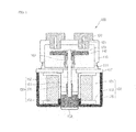
- FIG. 1 is a longitudinal sectional view showing the electronic switch according to the first embodiment
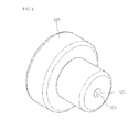
- FIG. 2 is a perspective view showing a fixed contact point according to the first embodiment
- FIGS. 3 to 5 are views showing the states of an off-operation of the electronic switch according to the first embodiment.
- FIG. 6 is a perspective view showing a fixed contact point included in an electronic switch according to the second embodiment.
- FIG. 1 is a longitudinal sectional view showing the electronic switch according to the first embodiment.
- FIG. 2 is a perspective view showing a fixed contact point included in the first embodiment.
- the electronic switch 100 may be placed at an outmost place in a housing 110.
- the electronic switch 100 may be formed in a polyhedral shape and have a hollow and an opened low surface.
- a seal cup 111 for connecting with a seal plate 137 which will be described below is provided at a low end of the housing 110.
- gas for arc extinction is injected into the housing 110.
- hydrogen (H 2 ) and nitrogen (N 2 ) may be injected into the housing 110 at the ratio of about 9:1.
- a fixed contact point 120 is installed in the housing 110.
- the fixed contact point 120 is installed while passing through a top surface of the housing 110, such that at least one portion of the fixed contact point 120 is placed in the housing 110.
- a gas inflow space 121 is formed in the fixed contact point 120.
- the gas inflow space 121 may be formed on one surface of the fixed contact point 120, one surface of a movable contact point 140 which will be described below, or both of the fixed and movable contact points 120 and 140.
- the case that the gas inflow space 121 is formed on one surface of the fixed contact point 120 will be described in the embodiment.
- One portion of the fixed contact point 120 is concaved such that the gas inflow space 121 is formed.
- one surface of the fixed contact point 120, which faces the movable contact point 140 is concaved therein, so that the gas inflow space 121 is formed.
- An inlet 123 of the gas inflow space 121 is placed on a low surface of the fixed contact point 120 which makes contact with the movable contact point 140. Gas flows into the gas inflow space 121 while the movable contact point 140 is making contact with the fixed contact point 120.
- the coil assembly 130 is installed in the housing 110.
- the coil assembly 130 includes a coil 131, a bobbin 133 and a yoke 135.
- the coil 131 is wound around an outer surface of the bobbin 133 which is formed in a cylindrical shape and has a hollow.
- the coil 131 generates an electromagnetic field when current is applied to the coil 131.
- the yoke 135 has a polyhedral shape surrounding the bobbin 133 and the coil 131.
- the seal plate 137 is installed on the top surface of the yoke 135.
- the seal plate 137 substantially seals an opened top surface of the yoke 135.
- a cylinder 139 extends by passing through the yoke 135.
- the cylinder 139 may be formed in a hollow cylindrical shape and may be placed in a longitudinal direction.
- the top surface of the cylinder 139 may be opened and the top end of the cylinder 139 may make contact with the low surface of the seal plate 137.
- the movable contact point 140 is movably installed in the housing 110.
- the movable contact point 140 makes contact with or is separated from the fixed contact point 120.
- One surface of the movable contact point 140 which faces the fixed contact point 120 is capable of making surface-contact with one surface of the fixed contact point 120 which faces the movable contact point 140. If the movable contact point 140 makes contact with the fixed contact point 120, the electronic switch 100 is switched on so that power is supplied to a load. If the movable contact point 140 is separated from the fixed contact point 120, the electronic switch 100 is switched off so that power is shut off.
- the movable contact point 140 allows the inlet 123 of the gas inflow space 121 to be selectively turned on or off. In other words, in the state that the fixed contact point 120 makes contact with the movable contact point 140, the movable contact point 140 allows the inlet 123 of the gas inflow space 121 to be closed. If the movable contact point 140 is spaced apart from the fixed contact point 120, the movable contact point 140 allows the inlet 123 of the gas inflow space 121 to be opened.
- the actuating unit 150 includes a fixed core 151 fixed inn the cylinder 139, a movable core 153 movably installed in the cylinder 139, a return spring 155 of providing elastic force to the movable core 153, and a movable shaft 157 of moving together with the movable core 153.
- the fixed core 151 is fixed at an upper portion in the cylinder 139.
- a low end of the fixed core 151 is spaced apart from a low end of the cylinder 139 by a predetermined distance.
- the movable core 153 is placed in the cylinder 139, which corresponds to a low portion of the fixed core 151.
- the movable core 153 moves closely the fixed coil 151 due to the electromagnetic filed generated from the coil 131.
- the return spring 155 applies elastic force to the movable core 153 such that the movable core 153 moves in a direction to be spaced apart from the fixed core 151.
- a coil spring may serve as the return spring 155.
- the coil spring is placed between the fixed and movable cores 151 and 153 and has both ends which are supported by the fixed and movable cores 151 and 153.
- a wipe spring 160 is provided to the movable core 153.
- the wipe spring 160 provide a contact pressure to the movable core 153 such that the contact state of the movable core 152 with the fixed contact point 120 is maintained.
- FIGS. 3 to 5 are views showing the states of an off-operation of the electronic switch according the first embodiment.
- the movable core 153 moves in the direction so that movable core 153 is spaced apart from the fixed core 151. As shown in FIG. 5 , as the movable core 153 moves, the movable contact point 140 is spaced apart from the fixed contact point 120.
- the inlet 123 of the gas inflow space 121 is opened.
- the inside of the gas inflow space 121 has a relatively high pressure
- the gas in the gas inflow space 121 is exhausted to an outside.
- the movable contact point 140 is pressed by the gas that is exhausted from the inside to the outside of the gas inflow space 121, the movable contact point 140 can be separated rapidly and substantially from the fixed contact point 120.
- FIG. 6 is a perspective view showing a fixed contact point of an electronic switch according to the second embodiment.
- the same reference numerals as those used in FIGS. 1 to 4 according to the first embodiment are assigned to the same portions as those used in FIGS. 1 to 4 according to the first embodiment and the detailed descriptions are omitted.
- a plurality of gas inflow spaces 221 are provided in a fixed contact point 220.
- An inlet 223 of the gas inflow space 221 is placed at one surface of the fixed contact point 220. Substantially, the inlet 223 is placed at one surface of the fixed contact point 220 making contact with the movable contact point 140.
- the gas inflow space 221 is disposed symmetrically with respect to the center of the cross section of the fixed contact point 220. Substantially, the gas inflow space 221 is disposed symmetrically with respect to the center of the one surface of the fixed contact point 220 which makes contact with the movable contact point 140.
Landscapes
- Physics & Mathematics (AREA)
- Electromagnetism (AREA)
- Arc-Extinguishing Devices That Are Switches (AREA)
- Contacts (AREA)
Abstract
Description
- The disclosure relates to an electronic switch.
- An electronic switch is a kind of an electrical contact switching device for supplying or shutting off current, and is installed in various industrial equipments, machines or vehicles. Such an electronic switch includes a fixed contact point and a movable contact point which selectively make contact with each other, and an electric actuator for driving the movable contact point according to an electrical signal in order to allow the fixed and movable contact points to make contact with each other or to be separated from each other.
- As generally known in the art, the electric actuator includes a coil for generating electromagnetic force, a fixed core fixed in the coil, a movable core movable closely to or away from the fixed core, a movable rod which moves in connection with the movement of the movable core and to which the movable contact point is fixed, and a return spring for applying elastic force to the movable core in order to allow the movable core to move away from the fixed core.
- In this case, if power is applied to the coil, the magnetic field is generated from the coil and the movable core moves toward the fixed core while overcoming the elastic force of the return spring by Fleming's left-hand rule. Thus, the movable rod moves in the same direction with the movable core, so that the movable contact point makes contact with the fixed contact point.
- To the contrary, if the power applied to the coil is shut off, the movable core moves away from the fixed core due to the elastic force of the return spring. Thus, the movable rod moves in the same direction with the movable core, so that the movable contact point is separated from the fixed contact point.
- According to the related art described above, the movable contract point is separated from the fixed contact point only by the elastic power of the return spring. Thus, since the fixed contact point is not rapidly separated from the fixed contact point, arc having the high temperature is generated while the fixed and movable contact points are being separated from each other, so that the fixed contact point and/or the movable contact point may be damaged.
- The disclosure provides an electronic switch in which the fixed and movable contact points can be more rapidly separated from each other.
- According to one embodiment, there is provided an electronic switch including a fixed contact point; a movable contact point making contact with or separated from the fixed contact point; and an actuating unit for moving the movable contact point in order to allow the movable contact point to make contact with or to be separated from the fixed contact point, wherein at least one gas inflow space is formed in at least one of the fixed and movable contact points, a gas which is injected into a space where the fixed and movable contact points make contact with or are separated from each other flows into the at least one gas inflow space while the fixed and movable contact points make contact with each other, and the gas in the at least one gas inflow space is exhausted to the space where the fixed and movable contact points make contact with or are separated from each other while the fixed and movable contact points are separated from each other.
- The gas inflow space may be formed by concaving down a portion of the fixed or movable contact point.
- The gas inflow spaces may be disposed symmetrically about a center of one surface of the fixed or movable contact point.
- The gas inflow space may be placed on one surface of the fixed contact point which faces the movable contact point.
- The gas may flow into the gas inflow space by the movable contact point which moves to make contact with the fixed contact point.
- The gas which flows into the gas inflow space is heated by an arc generated while the fixed and movable contact points are separated from each other, so that an inner pressure of the gas inflow space may be increased and the gas which flows into the gas inflow space may be exhausted into the space in which the fixed and movable contact points make contact with or are separated from each other.
- One surface of the fixed contact point which faces the movable contact point may make surface-contact with one surface of the movable contact point which faces the fixed contact point.
- According to the embodiment, the electronic switch includes the gas inflow space formed in the fixed contact point, and thus, the movable contact point can be separated from the fixed contact point by the gas exhausting to an outside of the gas inflow space. Therefore, the damage of the fixed contact point and/or the movable contact point, which is caused by the arc generated while the movable contact point is being separated from the fixed contact point, can be minimized, so that the durability and operation reliability of the product can be improved.
-
FIG. 1 is a longitudinal sectional view showing the electronic switch according to the first embodiment; -
FIG. 2 is a perspective view showing a fixed contact point according to the first embodiment; -
FIGS. 3 to 5 are views showing the states of an off-operation of the electronic switch according to the first embodiment; and -
FIG. 6 is a perspective view showing a fixed contact point included in an electronic switch according to the second embodiment. - Hereinafter, an electronic switch according to the first embodiment will be described with reference to accompanying drawings in detail.
-
FIG. 1 is a longitudinal sectional view showing the electronic switch according to the first embodiment.FIG. 2 is a perspective view showing a fixed contact point included in the first embodiment. - Referring to
FIG. 1 , theelectronic switch 100 may be placed at an outmost place in ahousing 110. Theelectronic switch 100 may be formed in a polyhedral shape and have a hollow and an opened low surface. Aseal cup 111 for connecting with aseal plate 137 which will be described below is provided at a low end of thehousing 110. - Meanwhile, gas for arc extinction is injected into the
housing 110. For example, hydrogen (H2) and nitrogen (N2) may be injected into thehousing 110 at the ratio of about 9:1. - A
fixed contact point 120 is installed in thehousing 110. Thefixed contact point 120 is installed while passing through a top surface of thehousing 110, such that at least one portion of thefixed contact point 120 is placed in thehousing 110. - In the embodiment, a
gas inflow space 121 is formed in thefixed contact point 120. Thegas inflow space 121 may be formed on one surface of thefixed contact point 120, one surface of amovable contact point 140 which will be described below, or both of the fixed andmovable contact points gas inflow space 121 is formed on one surface of thefixed contact point 120 will be described in the embodiment. One portion of thefixed contact point 120 is concaved such that thegas inflow space 121 is formed. In more detail, one surface of thefixed contact point 120, which faces themovable contact point 140, is concaved therein, so that thegas inflow space 121 is formed. Aninlet 123 of thegas inflow space 121 is placed on a low surface of thefixed contact point 120 which makes contact with themovable contact point 140. Gas flows into thegas inflow space 121 while themovable contact point 140 is making contact with thefixed contact point 120. - Further, a
coil assembly 130 is installed in thehousing 110. Thecoil assembly 130 includes acoil 131, abobbin 133 and ayoke 135. Thecoil 131 is wound around an outer surface of thebobbin 133 which is formed in a cylindrical shape and has a hollow. Thecoil 131 generates an electromagnetic field when current is applied to thecoil 131. Theyoke 135 has a polyhedral shape surrounding thebobbin 133 and thecoil 131. - Meanwhile, the
seal plate 137 is installed on the top surface of theyoke 135. Theseal plate 137 substantially seals an opened top surface of theyoke 135. - A
cylinder 139 extends by passing through theyoke 135. Thecylinder 139 may be formed in a hollow cylindrical shape and may be placed in a longitudinal direction. The top surface of thecylinder 139 may be opened and the top end of thecylinder 139 may make contact with the low surface of theseal plate 137. - The
movable contact point 140 is movably installed in thehousing 110. Themovable contact point 140 makes contact with or is separated from thefixed contact point 120. One surface of themovable contact point 140 which faces thefixed contact point 120 is capable of making surface-contact with one surface of thefixed contact point 120 which faces themovable contact point 140. If themovable contact point 140 makes contact with thefixed contact point 120, theelectronic switch 100 is switched on so that power is supplied to a load. If themovable contact point 140 is separated from thefixed contact point 120, theelectronic switch 100 is switched off so that power is shut off. - In the embodiment, the
movable contact point 140 allows theinlet 123 of thegas inflow space 121 to be selectively turned on or off. In other words, in the state that thefixed contact point 120 makes contact with themovable contact point 140, themovable contact point 140 allows theinlet 123 of thegas inflow space 121 to be closed. If themovable contact point 140 is spaced apart from thefixed contact point 120, themovable contact point 140 allows theinlet 123 of thegas inflow space 121 to be opened. - Meanwhile, the
movable contact point 140 moves by an actuatingunit 150, so that themovable contact point 140 makes contact with or is spaced apart from the fixedcontact point 120. The actuatingunit 150 includes a fixed core 151 fixed inn thecylinder 139, amovable core 153 movably installed in thecylinder 139, areturn spring 155 of providing elastic force to themovable core 153, and amovable shaft 157 of moving together with themovable core 153. - In more detail, the fixed core 151 is fixed at an upper portion in the
cylinder 139. A low end of the fixed core 151 is spaced apart from a low end of thecylinder 139 by a predetermined distance. - The
movable core 153 is placed in thecylinder 139, which corresponds to a low portion of the fixed core 151. Themovable core 153 moves closely the fixed coil 151 due to the electromagnetic filed generated from thecoil 131. - The
return spring 155 applies elastic force to themovable core 153 such that themovable core 153 moves in a direction to be spaced apart from the fixed core 151. For example, a coil spring may serve as thereturn spring 155. The coil spring is placed between the fixed andmovable cores 151 and 153 and has both ends which are supported by the fixed andmovable cores 151 and 153. - Further, the elastic force of a wipe
spring 160 is provided to themovable core 153. The wipespring 160 provide a contact pressure to themovable core 153 such that the contact state of the movable core 152 with the fixedcontact point 120 is maintained. - Hereinafter, the electronic switch according to the first embodiment will be described in detail with reference to accompanying drawings.
-
FIGS. 3 to 5 are views showing the states of an off-operation of the electronic switch according the first embodiment. - First, when the
electronic switch 100 is switched on, power is supplied to thecoil 131. Thus, the magnetic field is generated from thecoil 131 and themovable core 153 moves toward the fixed core 151 while overcoming the elastic force of thereturn spring 155 by Fleming's left-hand rule. As shown inFIG. 3 , as themovable core 153 moves, themovable contact point 140 moves toward the fixedcontact point 120. Thus, while themovable contact point 140 moves to make contact with the fixedcontact point 120, the gas stored in thehousing 110 flows into thegas inflow space 121. As shown inFIG. 4 , if the fixed and movable contact points 120 and 140 make contact with each other, theinlet 123 of thegas inflow space 121 is closed by themovable contact point 140. - Next, if the
electronic switch 100 is switched off, the power supplied to thecoil 131 is shut off. Thus, due to the elastic force of thereturn spring 155, themovable core 153 moves in the direction so thatmovable core 153 is spaced apart from the fixed core 151. As shown inFIG. 5 , as themovable core 153 moves, themovable contact point 140 is spaced apart from the fixedcontact point 120. - Meanwhile, while the fixed and movable contact points 120 and 140 are separated from each other, an arc having high temperature is generated. Then, the gas which is reserved in the
gas inflow space 121 is substantially heated by the arc. Thus, as the gas which flows into thegas inflow space 121 is increased, the internal pressure of thegas inflow space 121 is increased. - In this case, when the
movable contact point 140 moves to be spaced apart from the fixedcontact point 120, theinlet 123 of thegas inflow space 121 is opened. As described above, since the inside of thegas inflow space 121 has a relatively high pressure, if theinlet 123 of thegas inflow space 121 is opened, the gas in thegas inflow space 121 is exhausted to an outside. Thus, since themovable contact point 140 is pressed by the gas that is exhausted from the inside to the outside of thegas inflow space 121, themovable contact point 140 can be separated rapidly and substantially from the fixedcontact point 120. - Hereinafter, the electronic switch according to the second embodiment will be described in more detail with reference to the accompanying drawings.
-
FIG. 6 is a perspective view showing a fixed contact point of an electronic switch according to the second embodiment. The same reference numerals as those used inFIGS. 1 to 4 according to the first embodiment are assigned to the same portions as those used inFIGS. 1 to 4 according to the first embodiment and the detailed descriptions are omitted. - Referring to
FIG. 6 , according to the present embodiment, a plurality of gas inflow spaces 221 are provided in a fixedcontact point 220. An inlet 223 of the gas inflow space 221 is placed at one surface of the fixedcontact point 220. Substantially, the inlet 223 is placed at one surface of the fixedcontact point 220 making contact with themovable contact point 140. The gas inflow space 221 is disposed symmetrically with respect to the center of the cross section of the fixedcontact point 220. Substantially, the gas inflow space 221 is disposed symmetrically with respect to the center of the one surface of the fixedcontact point 220 which makes contact with themovable contact point 140. This is for applying substantially uniform external force over the whole area of themovable contact point 140 by the gas exhausted from the inside of the gas inflow space 221 to an outside. Thus, according to the embodiment, in the process of separating the fixed and movable contact points 220 and 140 from each other, the contact portions of both points can be separated entirely and uniformly from each other. - Although embodiments have been described with reference to a number of illustrative embodiments thereof, it should be understood that numerous other modifications and embodiments can be devised by those skilled in the art that will fall within the spirit and scope of the principles of this disclosure. More particularly, various variations and modifications are possible in the component parts and/or arrangements of the subject combination arrangement within the scope of the disclosure, the drawings and the appended claims. In addition to variations and modifications in the component parts and/or arrangements, alternative uses will also be apparent to those skilled in the art.
Claims (7)
- An electronic switch comprising:a fixed contact point;a movable contact point making contact with or separated from the fixed contact point; andan actuating unit for moving the movable contact point in order to allow the movable contact point to make contact with or to be separated from the fixed contact point,wherein at least one gas inflow space is formed in at least one of the fixed and movable contact points, a gas which is injected into a space where the fixed and movable contact points make contact with or are separated from each other flows into the at least one gas inflow space while the fixed and movable contact points make contact with each other, and the gas in the at least one gas inflow space is exhausted to the space where the fixed and movable contact points make contact with or are separated from each other while the fixed and movable contact points are separated from each other.
- The electronic switch of claim 1, wherein the gas inflow space is formed by concaving down a portion of the fixed or movable contact point.
- The electronic switch of claim 1, wherein the gas inflow spaces are disposed symmetrically about a center of one surface of the fixed or movable contact point.
- The electronic switch of claim 1 or 2, wherein the gas inflow space is placed on one surface of the fixed contact point which faces the movable contact point.
- The electronic switch of one of claim 4, wherein the gas flows into the gas inflow space by the movable contact point which moves to make contact with the fixed contact point.
- The electronic switch of claim 1 or 2, wherein the gas which flows into the gas inflow space is heated by an arc generated while the fixed and movable contact points are separated from each other, so that an inner pressure of the gas inflow space is increased and the gas which flows into the gas inflow space is exhausted into the space in which the fixed and movable contact points make contact with or are separated from each other.
- The electronic switch of claim 1 or 2, wherein one surface of the fixed contact point which faces the movable contact point makes surface-contact with one surface of the movable contact point which faces the fixed contact point.
Applications Claiming Priority (1)
| Application Number | Priority Date | Filing Date | Title |
|---|---|---|---|
| KR1020120070638A KR101696955B1 (en) | 2012-06-29 | 2012-06-29 | Electronics switch |
Publications (2)
| Publication Number | Publication Date |
|---|---|
| EP2680290A1 true EP2680290A1 (en) | 2014-01-01 |
| EP2680290B1 EP2680290B1 (en) | 2017-11-01 |
Family
ID=48628558
Family Applications (1)
| Application Number | Title | Priority Date | Filing Date |
|---|---|---|---|
| EP13172973.3A Active EP2680290B1 (en) | 2012-06-29 | 2013-06-20 | Electronic switch |
Country Status (6)
| Country | Link |
|---|---|
| US (1) | US9147538B2 (en) |
| EP (1) | EP2680290B1 (en) |
| JP (1) | JP5658318B2 (en) |
| KR (1) | KR101696955B1 (en) |
| CN (1) | CN103531367B (en) |
| ES (1) | ES2646772T3 (en) |
Cited By (2)
| Publication number | Priority date | Publication date | Assignee | Title |
|---|---|---|---|---|
| EP3345203A4 (en) * | 2015-08-31 | 2018-08-22 | BYD Company Limited | Relay |
| CN115083840A (en) * | 2021-03-15 | 2022-09-20 | 欧姆龙株式会社 | Electromagnetic relay |
Families Citing this family (1)
| Publication number | Priority date | Publication date | Assignee | Title |
|---|---|---|---|---|
| US10432559B2 (en) * | 2016-10-24 | 2019-10-01 | Snap Inc. | Generating and displaying customized avatars in electronic messages |
Citations (3)
| Publication number | Priority date | Publication date | Assignee | Title |
|---|---|---|---|---|
| DE9006430U1 (en) * | 1990-06-07 | 1990-08-09 | E. Dold & Söhne KG, 7743 Furtwangen | relay |
| EP2442332A1 (en) * | 2010-10-15 | 2012-04-18 | LSIS Co., Ltd. | Method for manufacturing sealed contactor |
| WO2012073468A1 (en) * | 2010-12-02 | 2012-06-07 | 富士電機株式会社 | Electromagnetic contactor, gas sealing method for electromagnetic contactor, and method for manufacturing electromagnetic contactor |
Family Cites Families (6)
| Publication number | Priority date | Publication date | Assignee | Title |
|---|---|---|---|---|
| JPS53117767A (en) * | 1977-03-24 | 1978-10-14 | Mitsubishi Electric Corp | Switch |
| JPS60123827A (en) | 1983-12-09 | 1985-07-02 | Canon Inc | Albada style finder |
| JPS60123827U (en) * | 1984-01-25 | 1985-08-21 | 松下電工株式会社 | contact switching device |
| CN200962406Y (en) * | 2006-07-03 | 2007-10-17 | 正泰集团股份有限公司 | Gas sealing low voltage electrical appliance with the operation contact |
| KR101013709B1 (en) * | 2008-12-03 | 2011-02-10 | 엘에스산전 주식회사 | High speed switch on switchboard |
| JP2012038684A (en) * | 2010-08-11 | 2012-02-23 | Fuji Electric Fa Components & Systems Co Ltd | Contact device and electromagnetic switch using the same |
-
2012
- 2012-06-29 KR KR1020120070638A patent/KR101696955B1/en active Active
-
2013
- 2013-06-18 US US13/921,061 patent/US9147538B2/en active Active
- 2013-06-20 ES ES13172973.3T patent/ES2646772T3/en active Active
- 2013-06-20 EP EP13172973.3A patent/EP2680290B1/en active Active
- 2013-06-28 JP JP2013136113A patent/JP5658318B2/en not_active Expired - Fee Related
- 2013-06-28 CN CN201310269141.9A patent/CN103531367B/en active Active
Patent Citations (3)
| Publication number | Priority date | Publication date | Assignee | Title |
|---|---|---|---|---|
| DE9006430U1 (en) * | 1990-06-07 | 1990-08-09 | E. Dold & Söhne KG, 7743 Furtwangen | relay |
| EP2442332A1 (en) * | 2010-10-15 | 2012-04-18 | LSIS Co., Ltd. | Method for manufacturing sealed contactor |
| WO2012073468A1 (en) * | 2010-12-02 | 2012-06-07 | 富士電機株式会社 | Electromagnetic contactor, gas sealing method for electromagnetic contactor, and method for manufacturing electromagnetic contactor |
Cited By (2)
| Publication number | Priority date | Publication date | Assignee | Title |
|---|---|---|---|---|
| EP3345203A4 (en) * | 2015-08-31 | 2018-08-22 | BYD Company Limited | Relay |
| CN115083840A (en) * | 2021-03-15 | 2022-09-20 | 欧姆龙株式会社 | Electromagnetic relay |
Also Published As
| Publication number | Publication date |
|---|---|
| KR101696955B1 (en) | 2017-01-16 |
| CN103531367B (en) | 2016-03-30 |
| CN103531367A (en) | 2014-01-22 |
| ES2646772T3 (en) | 2017-12-15 |
| EP2680290B1 (en) | 2017-11-01 |
| JP2014011161A (en) | 2014-01-20 |
| US9147538B2 (en) | 2015-09-29 |
| US20140001157A1 (en) | 2014-01-02 |
| KR20140003081A (en) | 2014-01-09 |
| JP5658318B2 (en) | 2015-01-21 |
Similar Documents
| Publication | Publication Date | Title |
|---|---|---|
| US8354905B2 (en) | Noise decreasing type electromagnetic switch | |
| KR101846224B1 (en) | Magnetic Switch | |
| CN106887365B (en) | DC relay | |
| US11830694B2 (en) | Direct current relay | |
| JP5405547B2 (en) | Electromagnetic switchgear | |
| CN102208304A (en) | Electromagnetic relay | |
| JP2012199117A (en) | Contact device and electromagnetic switching device using the same | |
| CN108140506A (en) | For the contact device and electric switch of electric switch | |
| KR20120115957A (en) | Switch having two sets of contact elements | |
| TWI751493B (en) | Relay | |
| US9147538B2 (en) | Electronic switch | |
| EP3016125B1 (en) | Crossbar structure of electromagnetic contactor | |
| US20190019645A1 (en) | Relay device | |
| JP5523594B2 (en) | Switch | |
| KR101771637B1 (en) | Sealed relay | |
| KR101410031B1 (en) | Magnetic Contactor having Arc Control Device using Insulating Oil | |
| CN102820173A (en) | Electrical contactor | |
| US9218931B2 (en) | Electromagnetic force driving device | |
| JP5281137B2 (en) | Normally closed contact type electromagnetic relay and automotive electromagnetic equipment using the same | |
| KR20200022073A (en) | Electro magnetic force driving device | |
| KR20200022072A (en) | Electro magnetic force driving device | |
| KR101547028B1 (en) | Electro magnetic force driving device | |
| US9214266B2 (en) | Electromagnetic force driving device | |
| KR20170004707A (en) | relay |
Legal Events
| Date | Code | Title | Description |
|---|---|---|---|
| PUAI | Public reference made under article 153(3) epc to a published international application that has entered the european phase |
Free format text: ORIGINAL CODE: 0009012 |
|
| AK | Designated contracting states |
Kind code of ref document: A1 Designated state(s): AL AT BE BG CH CY CZ DE DK EE ES FI FR GB GR HR HU IE IS IT LI LT LU LV MC MK MT NL NO PL PT RO RS SE SI SK SM TR |
|
| AX | Request for extension of the european patent |
Extension state: BA ME |
|
| 17P | Request for examination filed |
Effective date: 20140217 |
|
| RBV | Designated contracting states (corrected) |
Designated state(s): AL AT BE BG CH CY CZ DE DK EE ES FI FR GB GR HR HU IE IS IT LI LT LU LV MC MK MT NL NO PL PT RO RS SE SI SK SM TR |
|
| 17Q | First examination report despatched |
Effective date: 20161020 |
|
| GRAP | Despatch of communication of intention to grant a patent |
Free format text: ORIGINAL CODE: EPIDOSNIGR1 |
|
| RIC1 | Information provided on ipc code assigned before grant |
Ipc: H01H 50/54 20060101ALI20170616BHEP Ipc: H01H 51/29 20060101ALI20170616BHEP Ipc: H01H 50/02 20060101ALN20170616BHEP Ipc: H01H 9/34 20060101ALN20170616BHEP Ipc: H01H 9/30 20060101AFI20170616BHEP |
|
| INTG | Intention to grant announced |
Effective date: 20170710 |
|
| GRAS | Grant fee paid |
Free format text: ORIGINAL CODE: EPIDOSNIGR3 |
|
| GRAA | (expected) grant |
Free format text: ORIGINAL CODE: 0009210 |
|
| AK | Designated contracting states |
Kind code of ref document: B1 Designated state(s): AL AT BE BG CH CY CZ DE DK EE ES FI FR GB GR HR HU IE IS IT LI LT LU LV MC MK MT NL NO PL PT RO RS SE SI SK SM TR |
|
| REG | Reference to a national code |
Ref country code: GB Ref legal event code: FG4D |
|
| REG | Reference to a national code |
Ref country code: CH Ref legal event code: EP Ref country code: AT Ref legal event code: REF Ref document number: 942801 Country of ref document: AT Kind code of ref document: T Effective date: 20171115 |
|
| REG | Reference to a national code |
Ref country code: IE Ref legal event code: FG4D |
|
| REG | Reference to a national code |
Ref country code: DE Ref legal event code: R096 Ref document number: 602013028653 Country of ref document: DE |
|
| REG | Reference to a national code |
Ref country code: ES Ref legal event code: FG2A Ref document number: 2646772 Country of ref document: ES Kind code of ref document: T3 Effective date: 20171215 |
|
| REG | Reference to a national code |
Ref country code: NL Ref legal event code: MP Effective date: 20171101 |
|
| REG | Reference to a national code |
Ref country code: LT Ref legal event code: MG4D |
|
| REG | Reference to a national code |
Ref country code: FR Ref legal event code: PLFP Year of fee payment: 6 |
|
| REG | Reference to a national code |
Ref country code: AT Ref legal event code: MK05 Ref document number: 942801 Country of ref document: AT Kind code of ref document: T Effective date: 20171101 |
|
| PG25 | Lapsed in a contracting state [announced via postgrant information from national office to epo] |
Ref country code: NL Free format text: LAPSE BECAUSE OF FAILURE TO SUBMIT A TRANSLATION OF THE DESCRIPTION OR TO PAY THE FEE WITHIN THE PRESCRIBED TIME-LIMIT Effective date: 20171101 Ref country code: FI Free format text: LAPSE BECAUSE OF FAILURE TO SUBMIT A TRANSLATION OF THE DESCRIPTION OR TO PAY THE FEE WITHIN THE PRESCRIBED TIME-LIMIT Effective date: 20171101 Ref country code: NO Free format text: LAPSE BECAUSE OF FAILURE TO SUBMIT A TRANSLATION OF THE DESCRIPTION OR TO PAY THE FEE WITHIN THE PRESCRIBED TIME-LIMIT Effective date: 20180201 Ref country code: SE Free format text: LAPSE BECAUSE OF FAILURE TO SUBMIT A TRANSLATION OF THE DESCRIPTION OR TO PAY THE FEE WITHIN THE PRESCRIBED TIME-LIMIT Effective date: 20171101 Ref country code: LT Free format text: LAPSE BECAUSE OF FAILURE TO SUBMIT A TRANSLATION OF THE DESCRIPTION OR TO PAY THE FEE WITHIN THE PRESCRIBED TIME-LIMIT Effective date: 20171101 |
|
| PG25 | Lapsed in a contracting state [announced via postgrant information from national office to epo] |
Ref country code: AT Free format text: LAPSE BECAUSE OF FAILURE TO SUBMIT A TRANSLATION OF THE DESCRIPTION OR TO PAY THE FEE WITHIN THE PRESCRIBED TIME-LIMIT Effective date: 20171101 Ref country code: RS Free format text: LAPSE BECAUSE OF FAILURE TO SUBMIT A TRANSLATION OF THE DESCRIPTION OR TO PAY THE FEE WITHIN THE PRESCRIBED TIME-LIMIT Effective date: 20171101 Ref country code: HR Free format text: LAPSE BECAUSE OF FAILURE TO SUBMIT A TRANSLATION OF THE DESCRIPTION OR TO PAY THE FEE WITHIN THE PRESCRIBED TIME-LIMIT Effective date: 20171101 Ref country code: BG Free format text: LAPSE BECAUSE OF FAILURE TO SUBMIT A TRANSLATION OF THE DESCRIPTION OR TO PAY THE FEE WITHIN THE PRESCRIBED TIME-LIMIT Effective date: 20180201 Ref country code: IS Free format text: LAPSE BECAUSE OF FAILURE TO SUBMIT A TRANSLATION OF THE DESCRIPTION OR TO PAY THE FEE WITHIN THE PRESCRIBED TIME-LIMIT Effective date: 20180301 Ref country code: LV Free format text: LAPSE BECAUSE OF FAILURE TO SUBMIT A TRANSLATION OF THE DESCRIPTION OR TO PAY THE FEE WITHIN THE PRESCRIBED TIME-LIMIT Effective date: 20171101 Ref country code: GR Free format text: LAPSE BECAUSE OF FAILURE TO SUBMIT A TRANSLATION OF THE DESCRIPTION OR TO PAY THE FEE WITHIN THE PRESCRIBED TIME-LIMIT Effective date: 20180202 |
|
| PG25 | Lapsed in a contracting state [announced via postgrant information from national office to epo] |
Ref country code: DK Free format text: LAPSE BECAUSE OF FAILURE TO SUBMIT A TRANSLATION OF THE DESCRIPTION OR TO PAY THE FEE WITHIN THE PRESCRIBED TIME-LIMIT Effective date: 20171101 Ref country code: SK Free format text: LAPSE BECAUSE OF FAILURE TO SUBMIT A TRANSLATION OF THE DESCRIPTION OR TO PAY THE FEE WITHIN THE PRESCRIBED TIME-LIMIT Effective date: 20171101 Ref country code: CZ Free format text: LAPSE BECAUSE OF FAILURE TO SUBMIT A TRANSLATION OF THE DESCRIPTION OR TO PAY THE FEE WITHIN THE PRESCRIBED TIME-LIMIT Effective date: 20171101 Ref country code: CY Free format text: LAPSE BECAUSE OF FAILURE TO SUBMIT A TRANSLATION OF THE DESCRIPTION OR TO PAY THE FEE WITHIN THE PRESCRIBED TIME-LIMIT Effective date: 20171101 Ref country code: EE Free format text: LAPSE BECAUSE OF FAILURE TO SUBMIT A TRANSLATION OF THE DESCRIPTION OR TO PAY THE FEE WITHIN THE PRESCRIBED TIME-LIMIT Effective date: 20171101 |
|
| REG | Reference to a national code |
Ref country code: DE Ref legal event code: R097 Ref document number: 602013028653 Country of ref document: DE |
|
| PG25 | Lapsed in a contracting state [announced via postgrant information from national office to epo] |
Ref country code: PL Free format text: LAPSE BECAUSE OF FAILURE TO SUBMIT A TRANSLATION OF THE DESCRIPTION OR TO PAY THE FEE WITHIN THE PRESCRIBED TIME-LIMIT Effective date: 20171101 Ref country code: SM Free format text: LAPSE BECAUSE OF FAILURE TO SUBMIT A TRANSLATION OF THE DESCRIPTION OR TO PAY THE FEE WITHIN THE PRESCRIBED TIME-LIMIT Effective date: 20171101 Ref country code: RO Free format text: LAPSE BECAUSE OF FAILURE TO SUBMIT A TRANSLATION OF THE DESCRIPTION OR TO PAY THE FEE WITHIN THE PRESCRIBED TIME-LIMIT Effective date: 20171101 |
|
| PLBE | No opposition filed within time limit |
Free format text: ORIGINAL CODE: 0009261 |
|
| STAA | Information on the status of an ep patent application or granted ep patent |
Free format text: STATUS: NO OPPOSITION FILED WITHIN TIME LIMIT |
|
| 26N | No opposition filed |
Effective date: 20180802 |
|
| PG25 | Lapsed in a contracting state [announced via postgrant information from national office to epo] |
Ref country code: SI Free format text: LAPSE BECAUSE OF FAILURE TO SUBMIT A TRANSLATION OF THE DESCRIPTION OR TO PAY THE FEE WITHIN THE PRESCRIBED TIME-LIMIT Effective date: 20171101 |
|
| REG | Reference to a national code |
Ref country code: CH Ref legal event code: PL |
|
| REG | Reference to a national code |
Ref country code: BE Ref legal event code: MM Effective date: 20180630 |
|
| REG | Reference to a national code |
Ref country code: IE Ref legal event code: MM4A |
|
| PG25 | Lapsed in a contracting state [announced via postgrant information from national office to epo] |
Ref country code: LU Free format text: LAPSE BECAUSE OF NON-PAYMENT OF DUE FEES Effective date: 20180620 Ref country code: MC Free format text: LAPSE BECAUSE OF FAILURE TO SUBMIT A TRANSLATION OF THE DESCRIPTION OR TO PAY THE FEE WITHIN THE PRESCRIBED TIME-LIMIT Effective date: 20171101 |
|
| PG25 | Lapsed in a contracting state [announced via postgrant information from national office to epo] |
Ref country code: IE Free format text: LAPSE BECAUSE OF NON-PAYMENT OF DUE FEES Effective date: 20180620 Ref country code: LI Free format text: LAPSE BECAUSE OF NON-PAYMENT OF DUE FEES Effective date: 20180630 Ref country code: CH Free format text: LAPSE BECAUSE OF NON-PAYMENT OF DUE FEES Effective date: 20180630 |
|
| PG25 | Lapsed in a contracting state [announced via postgrant information from national office to epo] |
Ref country code: BE Free format text: LAPSE BECAUSE OF NON-PAYMENT OF DUE FEES Effective date: 20180630 |
|
| PG25 | Lapsed in a contracting state [announced via postgrant information from national office to epo] |
Ref country code: MT Free format text: LAPSE BECAUSE OF NON-PAYMENT OF DUE FEES Effective date: 20180620 |
|
| PG25 | Lapsed in a contracting state [announced via postgrant information from national office to epo] |
Ref country code: TR Free format text: LAPSE BECAUSE OF FAILURE TO SUBMIT A TRANSLATION OF THE DESCRIPTION OR TO PAY THE FEE WITHIN THE PRESCRIBED TIME-LIMIT Effective date: 20171101 |
|
| PG25 | Lapsed in a contracting state [announced via postgrant information from national office to epo] |
Ref country code: PT Free format text: LAPSE BECAUSE OF FAILURE TO SUBMIT A TRANSLATION OF THE DESCRIPTION OR TO PAY THE FEE WITHIN THE PRESCRIBED TIME-LIMIT Effective date: 20171101 Ref country code: HU Free format text: LAPSE BECAUSE OF FAILURE TO SUBMIT A TRANSLATION OF THE DESCRIPTION OR TO PAY THE FEE WITHIN THE PRESCRIBED TIME-LIMIT; INVALID AB INITIO Effective date: 20130620 |
|
| PG25 | Lapsed in a contracting state [announced via postgrant information from national office to epo] |
Ref country code: MK Free format text: LAPSE BECAUSE OF NON-PAYMENT OF DUE FEES Effective date: 20171101 |
|
| PG25 | Lapsed in a contracting state [announced via postgrant information from national office to epo] |
Ref country code: AL Free format text: LAPSE BECAUSE OF FAILURE TO SUBMIT A TRANSLATION OF THE DESCRIPTION OR TO PAY THE FEE WITHIN THE PRESCRIBED TIME-LIMIT Effective date: 20171101 |
|
| PGFP | Annual fee paid to national office [announced via postgrant information from national office to epo] |
Ref country code: GB Payment date: 20200408 Year of fee payment: 8 |
|
| GBPC | Gb: european patent ceased through non-payment of renewal fee |
Effective date: 20210620 |
|
| PG25 | Lapsed in a contracting state [announced via postgrant information from national office to epo] |
Ref country code: GB Free format text: LAPSE BECAUSE OF NON-PAYMENT OF DUE FEES Effective date: 20210620 |
|
| P01 | Opt-out of the competence of the unified patent court (upc) registered |
Effective date: 20230625 |
|
| PGFP | Annual fee paid to national office [announced via postgrant information from national office to epo] |
Ref country code: FR Payment date: 20250307 Year of fee payment: 13 |
|
| PGFP | Annual fee paid to national office [announced via postgrant information from national office to epo] |
Ref country code: IT Payment date: 20250306 Year of fee payment: 13 |
|
| PGFP | Annual fee paid to national office [announced via postgrant information from national office to epo] |
Ref country code: DE Payment date: 20250305 Year of fee payment: 13 |
|
| PGFP | Annual fee paid to national office [announced via postgrant information from national office to epo] |
Ref country code: ES Payment date: 20250714 Year of fee payment: 13 |