EP2680222A1 - Verfahren, Vorrichtung und Computerprogrammprodukt zur Verarbeitung von Medieninhalten - Google Patents
Verfahren, Vorrichtung und Computerprogrammprodukt zur Verarbeitung von Medieninhalten Download PDFInfo
- Publication number
- EP2680222A1 EP2680222A1 EP13173908.8A EP13173908A EP2680222A1 EP 2680222 A1 EP2680222 A1 EP 2680222A1 EP 13173908 A EP13173908 A EP 13173908A EP 2680222 A1 EP2680222 A1 EP 2680222A1
- Authority
- EP
- European Patent Office
- Prior art keywords
- side edge
- edge portions
- images
- image
- edge portion
- Prior art date
- Legal status (The legal status is an assumption and is not a legal conclusion. Google has not performed a legal analysis and makes no representation as to the accuracy of the status listed.)
- Withdrawn
Links
Images


Classifications
-
- G—PHYSICS
- G06—COMPUTING; CALCULATING OR COUNTING
- G06T—IMAGE DATA PROCESSING OR GENERATION, IN GENERAL
- G06T3/00—Geometric image transformation in the plane of the image
- G06T3/40—Scaling the whole image or part thereof
- G06T3/4038—Scaling the whole image or part thereof for image mosaicing, i.e. plane images composed of plane sub-images
-
- H—ELECTRICITY
- H04—ELECTRIC COMMUNICATION TECHNIQUE
- H04N—PICTORIAL COMMUNICATION, e.g. TELEVISION
- H04N23/00—Cameras or camera modules comprising electronic image sensors; Control thereof
- H04N23/60—Control of cameras or camera modules
- H04N23/698—Control of cameras or camera modules for achieving an enlarged field of view, e.g. panoramic image capture
-
- G—PHYSICS
- G06—COMPUTING; CALCULATING OR COUNTING
- G06T—IMAGE DATA PROCESSING OR GENERATION, IN GENERAL
- G06T7/00—Image analysis
- G06T7/30—Determination of transform parameters for the alignment of images, i.e. image registration
- G06T7/33—Determination of transform parameters for the alignment of images, i.e. image registration using feature-based methods
-
- G—PHYSICS
- G06—COMPUTING; CALCULATING OR COUNTING
- G06T—IMAGE DATA PROCESSING OR GENERATION, IN GENERAL
- G06T2207/00—Indexing scheme for image analysis or image enhancement
- G06T2207/20—Special algorithmic details
- G06T2207/20068—Projection on vertical or horizontal image axis
-
- G—PHYSICS
- G06—COMPUTING; CALCULATING OR COUNTING
- G06T—IMAGE DATA PROCESSING OR GENERATION, IN GENERAL
- G06T2207/00—Indexing scheme for image analysis or image enhancement
- G06T2207/20—Special algorithmic details
- G06T2207/20072—Graph-based image processing
Definitions
- Various implementations relate generally to method, apparatus, and computer program product for arranging images in a sequence.
- a panorama image refers to an image captured with an extended field of view in one or more directions (for example, horizontally or vertically).
- the extended field of view is a wide-angle representation beyond that captured by an image sensor.
- a panorama image includes a plurality of images that may be captured and arranged sequentially.
- a method comprising: determining a set of first-side edge portions and a set of second-side edge portions associated with a plurality of images; determining a first plurality of edge pairs between the set of first-side edge portions and the set of second-side edge portions, an edge pair of the first plurality of edge pair comprising a first-side edge portion of an image and a second-side edge portion of an another image of the plurality of images; assigning a first set of weights to the first plurality of edge pairs based at least on a pair-wise matching between the set of first-side edge portions and the set of second-side edge portions; and arranging the plurality of images in a first sequence based on the first set of weights assigned to the first plurality of edge pairs.
- an apparatus comprising at least one processor; and at least one memory comprising computer program code, the at least one memory and the computer program code configured to, with the at least one processor, cause the apparatus to at least perform: determine a set of first-side edge portions and a set of second-side edge portions associated with a plurality of images; determine a first plurality of edge pairs between the set of first-side edge portions and the set of second-side edge portions, an edge pair of the first plurality of edge pair comprising a first-side edge portion of an image and a second-side edge portion of an another image of the first plurality of images; assign a first set of weights to the first plurality edge pairs based at least on a pair-wise matching between the set of first-side edge portions and the set of second-side edge portions; and arrange the plurality of images in a first sequence based on the first set of weights assigned to the first plurality of edge pairs.
- a computer program product comprising at least one computer-readable storage medium, the computer-readable storage medium comprising a set of instructions, which, when executed by one or more processors, cause an apparatus to at least perform: determine a set of first-side edge portions and a set of second-side edge portions associated with a plurality of images; determine a first plurality of edge pairs between the set of first-side edge portions and the set of second-side edge portions, an edge pair of the first plurality of edge pair comprising a first-side edge portion of an image and a second-side edge portion of an another image of the plurality of images; assign a first set of weights to the first plurality of edge pairs based at least on a pair-wise matching between the set of first-side edge portions and the set of second-side edge portions; and arrange the plurality of images in a first sequence based on the first set of weights assigned to the first plurality of edge pairs.
- an apparatus comprising: means for determining a set of first-side edge portions and a set of second-side edge portions associated with a plurality of images; means for determining a first plurality of edge pairs between the set of first-side edge portions and the set of second-side edge portions, an edge pair of the first plurality of edge pairs comprising a first-side edge portion of an image and a second-side edge portion of an another image of the plurality of images; assign a first set of weights to the first plurality edge pairs based at least on a pair-wise matching between the set of first-side edge portions and the set of second-side edge portions; and means for arranging the plurality of images in a first sequence based on the first set of weights assigned to the first plurality of edge pairs.
- a computer program comprising program instructions which when executed by an apparatus, cause the apparatus to: determine a set of first-side edge portions and a set of second-side edge portions associated with a plurality of images; determine a first plurality of edge pairs between the set of first-side edge portions and the set of second-side edge portions, an edge pair of the first plurality of edge pair comprising a first-side edge portion of an image and a second-side edge portion of an another image of the plurality of images; assign a first set of weights to the first plurality edge pairs based at least on a pair-wise matching between the set of first-side edge portions and the set of second-side edge portions; and arrange the plurality of images in a first sequence based on the first set of weights assigned to the first plurality of edge pairs.
- FIGURES 1 through 8B of the drawings Example embodiments and their potential effects are understood by referring to FIGURES 1 through 8B of the drawings.
- FIGURE 1 illustrates a device 100 in accordance with an example embodiment. It should be understood, however, that the device 100 as illustrated and hereinafter described is merely illustrative of one type of device that may benefit from various embodiments, therefore, should not be taken to limit the scope of the embodiments. As such, it should be appreciated that at least some of the components described below in connection with the device 100 may be optional and thus in an example embodiment may include more, less or different components than those described in connection with the example embodiment of FIGURE 1 .
- the device 100 could be any of a number of types of mobile electronic devices, for example, portable digital assistants (PDAs), pagers, mobile televisions, gaming devices, cellular phones, all types of computers (for example, laptops, mobile computers or desktops), cameras, audio/video players, radios, global positioning system (GPS) devices, media players, mobile digital assistants, or any combination of the aforementioned, and other types of communications devices.
- PDAs portable digital assistants
- pagers mobile televisions
- gaming devices for example, laptops, mobile computers or desktops
- computers for example, laptops, mobile computers or desktops
- GPS global positioning system
- media players media players
- mobile digital assistants or any combination of the aforementioned, and other types of communications devices.
- the device 100 may include an antenna 102 (or multiple antennas) in operable communication with a transmitter 104 and a receiver 106.
- the device 100 may further include an apparatus, such as a controller 108 or other processing device that provides signals to and receives signals from the transmitter 104 and receiver 106, respectively.
- the signals may include signaling information in accordance with the air interface standard of the applicable cellular system, and/or may also include data corresponding to user speech, received data and/or user generated data.
- the device 100 may be capable of operating with one or more air interface standards, communication protocols, modulation types, and access types.
- the device 100 may be capable of operating in accordance with any of a number of first, second, third and/or fourth-generation communication protocols or the like.
- the device 100 may be capable of operating in accordance with second-generation (2G) wireless communication protocols IS-136 (time division multiple access (TDMA)), GSM (global system for mobile communication), and IS-95 (code division multiple access (CDMA)), or with third-generation (3G) wireless communication protocols, such as Universal Mobile Telecommunications System (UMTS), CDMA1000, wideband CDMA (WCDMA) and time division-synchronous CDMA (TD-SCDMA), with 3.9G wireless communication protocol such as evolved- universal terrestrial radio access network (E-UTRAN), with fourth-generation (4G) wireless communication protocols, or the like.
- 2G wireless communication protocols IS-136 (time division multiple access (TDMA)
- GSM global system for mobile communication
- IS-95 code division multiple access
- third-generation (3G) wireless communication protocols such as Universal Mobile Telecommunications System (UMTS), CDMA1000, wideband CDMA (WCDMA) and time division-synchronous CDMA (TD-SCDMA), with 3.9G wireless communication protocol such as evolved- universal terrestrial radio access network (E-UTRAN
- computer networks such as the Internet, local area network, wide area networks, and the like; short range wireless communication networks such as Bluetooth® networks, Zigbee® networks, Institute of Electric and Electronic Engineers (IEEE) 802.11x networks, and the like; wireline telecommunication networks such as public switched telephone network (PSTN).
- PSTN public switched telephone network
- the controller 108 may include circuitry implementing, among others, audio and logic functions of the device 100.
- the controller 108 may include, but are not limited to, one or more digital signal processor devices, one or more microprocessor devices, one or more processor(s) with accompanying digital signal processor(s), one or more processor(s) without accompanying digital signal processor(s), one or more special-purpose computer chips, one or more field-programmable gate arrays (FPGAs), one or more controllers, one or more application-specific integrated circuits (ASICs), one or more computer(s), various analog to digital converters, digital to analog converters, and/or other support circuits. Control and signal processing functions of the device 100 are allocated between these devices according to their respective capabilities.
- the controller 108 thus may also include the functionality to convolutionally encode and interleave message and data prior to modulation and transmission.
- the controller 108 may additionally include an internal voice coder, and may include an internal data modem.
- the controller 108 may include functionality to operate one or more software programs, which may be stored in a memory.
- the controller 108 may be capable of operating a connectivity program, such as a conventional Web browser.
- the connectivity program may then allow the device 100 to transmit and receive Web content, such as location-based content and/or other web page content, according to a Wireless Application Protocol (WAP), Hypertext Transfer Protocol (HTTP) and/or the like.
- WAP Wireless Application Protocol
- HTTP Hypertext Transfer Protocol
- the controller 108 may be embodied as a multi-core processor such as a dual or quad core processor. However, any number of processors may be included in the controller 108.
- the device 100 may also comprise a user interface including an output device such as a ringer 110, an earphone or speaker 112, a microphone 114, a display 116, and a user input interface, which may be coupled to the controller 108.
- the user input interface which allows the device 100 to receive data, may include any of a number of devices allowing the device 100 to receive data, such as a keypad 118, a touch display, a microphone or other input device.
- the keypad 118 may include numeric (0-9) and related keys (#, *), and other hard and soft keys used for operating the device 100.
- the keypad 118 may include a conventional QWERTY keypad arrangement.
- the keypad 118 may also include various soft keys with associated functions.
- the device 100 may include an interface device such as a joystick or other user input interface.
- the device 100 further includes a battery 120, such as a vibrating battery pack, for powering various circuits that are used to operate the device 100, as well as optionally providing mechanical vibration as a detectable output.
- the device 100 includes a media capturing element, such as a camera, video and/or audio module, in communication with the controller 108.
- the media capturing element may be any means for capturing an image, video and/or audio for storage, display or transmission.
- the media capturing element is a camera module 122 which may include a digital camera capable of forming a digital image file from a captured image.
- the camera module 122 includes all hardware, such as a lens or other optical component(s), and software for creating a digital image file from a captured image.
- the camera module 122 may include the hardware needed to view an image, while a memory device of the device 100 stores instructions for execution by the controller 108 in the form of software to create a digital image file from a captured image.
- the camera module 122 may further include a processing element such as a co-processor, which assists the controller 108 in processing image data and an encoder and/or decoder for compressing and/or decompressing image data.
- the encoder and/or decoder may encode and/or decode according to a JPEG standard format or another like format.
- the encoder and/or decoder may employ any of a plurality of standard formats such as, for example, standards associated with H.261, H.262/ MPEG-2, H.263, H.264, H.264/MPEG-4, MPEG-4, and the like.
- the camera module 122 may provide live image data to the display 116.
- the display 116 may be located on one side of the device 100 and the camera module 122 may include a lens positioned on the opposite side of the device 100 with respect to the display 116 to enable the camera module 122 to capture images on one side of the device 100 and present a view of such images to the user positioned on the other side of the device 100.
- the device 100 may further include a user identity module (UIM) 124.
- the UIM 124 may be a memory device having a processor built in.
- the UIM 124 may include, for example, a subscriber identity module (SIM), a universal integrated circuit card (UICC), a universal subscriber identity module (USIM), a removable user identity module (R-UIM), or any other smart card.
- SIM subscriber identity module
- UICC universal integrated circuit card
- USIM universal subscriber identity module
- R-UIM removable user identity module
- the UIM 124 typically stores information elements related to a mobile subscriber.
- the device 100 may be equipped with memory.
- the device 100 may include volatile memory 126, such as volatile random access memory (RAM) including a cache area for the temporary storage of data.
- RAM volatile random access memory
- the device 100 may also include other non-volatile memory 128, which may be embedded and/or may be removable.
- the non-volatile memory 128 may additionally or alternatively comprise an electrically erasable programmable read only memory (EEPROM), flash memory, hard drive, or the like.
- EEPROM electrically erasable programmable read only memory
- the memories may store any number of pieces of information, and data, used by the device 100 to implement the functions of the device 100.
- FIGURE 2 illustrates an apparatus 200 for arranging images in a sequence in accordance with an example embodiment.
- the apparatus 200 for arranging images may be employed, for example, in the device 100 of FIGURE 1 .
- the apparatus 200 may also be employed on a variety of other devices both mobile and fixed, and therefore, embodiments should not be limited to application on devices such as the device 100 of FIGURE 1 .
- embodiments may be employed on a combination of devices including, for example, those listed above. Accordingly, various embodiments may be embodied wholly at a single device, (for example, the device 100 or in a combination of devices).
- the devices or elements described below may not be mandatory and thus some may be omitted in certain embodiments.
- the apparatus 200 includes or otherwise is in communication with at least one processor 202 and at least one memory 204.
- the at least one memory 204 include, but are not limited to, volatile and/or non-volatile memories.
- volatile memory include, but are not limited to, random access memory, dynamic random access memory, static random access memory, and the like.
- the non-volatile memory includes, but are not limited to, hard disks, magnetic tapes, optical disks, programmable read only memory, erasable programmable read only memory, electrically erasable programmable read only memory, flash memory, and the like.
- the memory 204 may be configured to store information, data, applications, instructions or the like for enabling the apparatus 200 to carry out various functions in accordance with various example embodiments.
- the memory 204 may be configured to buffer input data comprising multimedia content for processing by the processor 202. Additionally or alternatively, the memory 204 may be configured to store instructions for execution by the processor 202.
- the processor 202 may include the controller 108.
- the processor 202 may be embodied in a number of different ways.
- the processor 202 may be embodied as a multi-core processor, a single core processor; or combination of multi-core processors and single core processors.
- the processor 202 may be embodied as one or more of various processing means such as a coprocessor, a microprocessor, a controller, a digital signal processor (DSP), processing circuitry with or without an accompanying DSP, or various other processing devices including integrated circuits such as, for example, an application specific integrated circuit (ASIC), a field programmable gate array (FPGA), a microcontroller unit (MCU), a hardware accelerator, a special-purpose computer chip, or the like.
- various processing means such as a coprocessor, a microprocessor, a controller, a digital signal processor (DSP), processing circuitry with or without an accompanying DSP, or various other processing devices including integrated circuits such as, for example, an application specific integrated circuit
- the multi-core processor may be configured to execute instructions stored in the memory 204 or otherwise accessible to the processor 202.
- the processor 202 may be configured to execute hard coded functionality.
- the processor 202 may represent an entity, for example, physically embodied in circuitry, capable of performing operations according to various embodiments while configured accordingly.
- the processor 202 may be specifically configured hardware for conducting the operations described herein.
- the processor 202 may specifically configure the processor 202 to perform the algorithms and/or operations described herein when the instructions are executed.
- the processor 202 may be a processor of a specific device, for example, a mobile terminal or network device adapted for employing embodiments by further configuration of the processor 202 by instructions for performing the algorithms and/or operations described herein.
- the processor 202 may include, among other things, a clock, an arithmetic logic unit (ALU) and logic gates configured to support operation of the processor 202.
- ALU arithmetic logic unit
- a user interface 206 may be in communication with the processor 202.
- Examples of the user interface 206 include, but are not limited to, input interface and/or output user interface.
- the input interface is configured to receive an indication of a user input.
- the output user interface provides an audible, visual, mechanical or other output and/or feedback to the user.
- Examples of the input interface may include, but are not limited to, a keyboard, a mouse, a joystick, a keypad, a touch screen, soft keys, and the like.
- the output interface may include, but are not limited to, a display such as light emitting diode display, thin-film transistor (TFT) display, liquid crystal displays, active-matrix organic light-emitting diode (AMOLED) display, a microphone, a speaker, ringers, vibrators, and the like.
- the user interface 206 may include, among other devices or elements, any or all of a speaker, a microphone, a display, and a keyboard, touch screen, or the like.
- the processor 202 may comprise user interface circuitry configured to control at least some functions of one or more elements of the user interface 206, such as, for example, a speaker, ringer, microphone, display, and/or the like.
- the processor 202 and/or user interface circuitry comprising the processor 202 may be configured to control one or more functions of one or more elements of the user interface 206 through computer program instructions, for example, software and/or firmware, stored on a memory, for example, the at least one memory 204, and/or the like, accessible to the processor 202.
- the apparatus 200 may include an electronic device.
- the electronic device include communication device, media capturing device with communication capabilities, computing devices, and the like.
- Some examples of the communication device may include a mobile phone, a personal digital assistant (PDA), and the like.
- Some examples of computing device may include a laptop, a personal computer, and the like.
- the communication device may include a user interface, for example, the UI 206, having user interface circuitry and user interface software configured to facilitate a user to control at least one function of the communication device through use of a display and further configured to respond to user inputs.
- the communication device may include a display circuitry configured to display at least a portion of the user interface of the communication device. The display and display circuitry may be configured to facilitate the user to control at least one function of the communication device.
- the communication device may be embodied as to include a transceiver.
- the transceiver may be any device operating or circuitry operating in accordance with software or otherwise embodied in hardware or a combination of hardware and software.
- the processor 202 operating under software control, or the processor 202 embodied as an ASIC or FPGA specifically configured to perform the operations described herein, or a combination thereof, thereby configures the apparatus or circuitry to perform the functions of the transceiver.
- the transceiver may be configured to receive multimedia content. Examples of multimedia content may include audio content, video content, data, and a combination thereof.
- the communication device may be embodied as to include an image sensor, such as an image sensor 208.
- the image sensor 208 may be in communication with the processor 202 and/or other components of the apparatus 200.
- the image sensor 208 may be in communication with other imaging circuitries and/or software, and is configured to capture digital images or to make a video or other graphic media files.
- the image sensor 208 and other circuitries, in combination, may be an example of the camera module 122 of the device 100.
- the components 202-208 may communicate with each other via a centralized circuit system 210 to perform ordering images in a sequence.
- the centralized circuit system 210 may be various devices configured to, among other things, provide or enable communication between the components 202-208 of the apparatus 200.
- the centralized circuit system 210 may be a central printed circuit board (PCB) such as a motherboard, main board, system board, or logic board.
- PCAs printed circuit assemblies
- the processor 202 is caused to, with the content of the memory 204, and optionally with other components described herein, to cause the apparatus 200 to arrange images in a sequence from the plurality of images.
- the images may include a plurality of successively captured images.
- the image sensor 208 may be configured to capture the video or the plurality of images.
- the plurality of successively captured images may not be arranged and/or stored in an order of capture of images.
- the plurality of images may be pre-recorded and stored in the apparatus 200.
- the plurality of images may be stored randomly.
- the plurality of images may be stored in an order of an image feature, such as brightness, color, and the like.
- arranging the plurality of images in an order may refer to the arrangement of the plurality of images in an order of capture of the plurality of images.
- the plurality of images may be captured by utilizing the camera module 122 of the device 100, and stored in the memory of the device 100.
- the device 100 may receive the plurality of images from internal memory such as hard drive, random access memory (RAM) of the apparatus 200, or from external storage medium such as DVD, Compact Disk (CD), flash drive, memory card, or from external storage locations through Internet, Bluetooth ® , and the like.
- the apparatus 200 may also receive the multimedia content from the memory 204.
- a processing means may be configured to arrange images in a sequence from the plurality of images.
- An example of the processing means may include the processor 202, which may be an example of the controller 108.
- the processor 202 is caused to, with the content of the memory 204, and optionally with other components described herein, to cause the apparatus 200 to determine a set of first-side edge portions and a set of second-side edge portions associated with the plurality of images.
- a first-side edge portion of the set of the first-side edge portions is opposite to a second-side edge portion of the set of second-side edge portions.
- the first-side edge portion and the second-side edge portion may comprise a left-side edge portion and a right-side edge portion, respectively associated with an image.
- the first-side edge portion and the second side edge portion may comprise a top-side edge portion and a bottom-side edge portion, respectively of the image.
- the plurality of images may be captured by rotating/moving an image capturing device in a direction, for example, in a horizontal direction or in a vertical direction.
- the image capturing device may capture a plurality of images such that images may comprise at least a portion overlapping with an adjacent image.
- a first image, a second image and a third image may be captured by moving the image capturing device in a horizontal direction, such that at least a right-side edge portion of the first image may overlap with a left-side edge portion of the second image, and a right-side edge portion of the second image may overlap with a left-side edge portion of the third image.
- a processing means may be configured to determine the set of first-side edge portions and the set of second-side edge portions associated with the plurality of images.
- An example of the processing means may include the processor 202, which may be an example of the controller 108.
- the processor 202 is caused to, with the content of the memory 204, and optionally with other components described herein, to cause the apparatus 200 to determine vector projections associated with the set of the first-side edge portions and the set of the second-side edge portions.
- the vector projections are configured to facilitate determination of a pair-wise matching between the set of first-side edge portions and the set of second-side edge portions.
- An example illustrating vector projections for images is explained in detail with reference to FIGURE 3 .
- a processing means may be configured to determine vector projections associated with the set of the first-side edge portions and the set of the second-side edge portions.
- An example of the processing means may include the processor 202, which may be an example of the controller 108.
- the processor 202 is caused to, with the content of the memory 204, and optionally with other components described herein, to cause the apparatus 200 to match the vector projections associated with the set of the first-side edge portions and the set of the second-side edge portions.
- the matching of the vector projections is performed to determine a first plurality of edge pairs between the set of first-side edge portions and the set of second-side edge portions.
- an edge pair of the first plurality of edge pair comprises a first-side edge portion of an image and a second-side edge portion of an another image.
- an edge pair may include a right-side edge portion of the first image and the left-side edge portion of the second image.
- another edge pair may comprise a right-side edge portion of the first image and the left-side edge portion of the third image.
- the matching of the vector projections may be performed based on a normalized cross correlation of the first plurality of edge pair.
- the normalized cross correlation is utilized as a similarity measure in determining a matching or overlapping between various images associated with a sequence.
- the NCC determines a pair of pixels in the left-side edge portions of an image and the right-side edge portions of another image such that a correlation coefficient is maximized. The difference between the pixels of the image coordinates of these two pixels gives the disparity for the pixel pair.
- the NCC gives an approximate matching between the first plurality of edge pairs.
- edge orientation between each edge pair of the first plurality of edge pairs may be determined.
- the edge orientation between the edge pairs may be determined based on a distribution of intensity gradients or edge directions in the associated images. For example, local object appearance and shape within an image may be described by utilizing the distribution of intensity gradients or edge directions.
- the image is partitioned in various blocks and for each block a histogram of gradient directions or edge orientations for the pixels within the block may be compiled. The combination of the histograms represents a descriptor or a weight associated with the pair-wise matching.
- edge orientation histograms may be computed for the edge pairs associated with the plurality of images.
- a distance between the EOG histograms may be determined based on Bhattacharya distance.
- Bhattacharya distance' may be utilized to compute an amount of matching between the edge portions associated with the images of the plurality of images.
- Bhattacharya distance is indicative of the distance between the edges of an image and another image associated with the plurality of images.
- a distance from a right-side edge portion of a first image to a left-side edge portion of a second image may be represented as D( i_right, i_left ) .
- a distance from left-side edge portion of a second image to the right-side edge portion of the first image may be represented as D( i_left, i_right ) .
- 'a' represents an image matching metric that may be utilized for matching the first side edge portion of the first image with the second side edge portion of the second image.
- examples of the metric 'a' may include, a Bhattacharya distance, cost of dynamic time warping (with integral projections as features), a cosine distance (with LBP histograms), or any other distance measure between two histograms or distributions.
- a NXN matrix may be computed such that the elements of the matrix comprise the distance of edges associated with edge pairs. It will be understood that the edge pairs comprising the first-edge portion and the second-edge portion from the same image may not be considered.
- a processing means may be configured to match the vector projections associated with the set of the first-side edge portions and the set of the second-side edge portions.
- An example of the processing means may include the processor 202, which may be an example of the controller 108.
- the processor 202 is caused to, with the content of the memory 204, and optionally with other components described herein, to cause the apparatus 200 to represent the first plurality of edge pairs by means of a bipartite graph for determining the first plurality of edge pairs.
- the bipartite graph comprises a plurality of nodes and a plurality of edges such that the plurality of edges connects every node to every other node.
- the plurality of nodes comprises a first set of nodes representing the set of first-side edge portions and second set of nodes representing the set of second-side edge portions of the plurality of images.
- a processing means may be configured to represent the first plurality of edge pairs by means of a bipartite graph for determining the first plurality of edge pairs.
- An example of the processing means may include the processor 202, which may be an example of the controller 108.
- the processor 202 is caused to, with the content of the memory 204, and optionally with other components described herein, to cause the apparatus 200 to assign a first set of weights to the first plurality of edge pairs based at least on the pair-wise matching between the set of first-side edge portions and the set of second-side edge portions.
- the first set of weights assigned to the first plurality edge pairs may be represented in form of a NXN matrix.
- the processor 202 is caused to, with the content of the memory 204, and optionally with other components described herein, to cause the apparatus 200 to generate a matrix of the first set of weights, such that the dimensions of the matrix are associated with a number of first-side edge portions and a number of second-side edge portions of the plurality of images.
- a processing means may be configured to assign first set of weights to the first plurality of edge pairs based at least on the pair-wise matching between the set of first-side edge portions and the set of second-side edge portions.
- An example of the processing means may include the processor 202, which may be an example of the controller 108.
- the processor 202 is caused to, with the content of the memory 204, and optionally with other components described herein, to cause the apparatus 200 to arrange the plurality of images in a first sequence based on the first set of weights assigned to the first plurality of edge pairs.
- the plurality of images are arranged in the first sequence by selecting, for at least one of the each row and each column of the matrix, an edge pair between the set of first-side edge portions and the set of second-side edge portions that is associated with a minimum weight.
- the minimum weight is associated with the maximum pair-wise matching.
- the first sequence of the plurality of image may be utilized for generating a panorama image.
- a panorama image may be generated, for instance by stitching the plurality of images arranged in the first sequence.
- the panorama image is a 360 degree panorama.
- the 360 degree panorama image may refer to a panorama image being generated by rotating and capturing a wide range image around a scene wherein the first end of the image is logically connected to the second end of the images. Accordingly the first-side edge portion of the first peripheral image is connected to the second-side edge portion of the second peripheral image.
- the panorama image is a non-360 degree image.
- the panorama image may be a 180 degree panorama image, wherein the first sequence comprises plurality of images arranged in a manner that the first side edge portion of the first peripheral image and the second-side edge portion of the second peripheral image of the sequence of images have substantially nothing in common.
- the processor 202 is caused to, with the content of the memory 204, and optionally with other components described herein, to cause the apparatus 200 to determine the at least one of first-side edge portion of the first peripheral image and the second-side edge portion of the second peripheral image by assuming a dummy first-side edge portion and a dummy second-side edge portion.
- the dummy first-side edge portion and the dummy-second side edge portion may be associated with a relatively high weight because of existence of high non-overlapping between the dummy-first side edge portion and the second-side edge portions, and between the dummy-second side edge portion and the first-side edge portions.
- j represent images
- N is the total number of images in the plurality of images
- M indicates a weight associated with a weak match.
- M may be a weight associated with a worst possible match.
- the values of Min_i_first and Min_i_second indicate the robust matches of edge pairs for every first-side edge portion and the second-side edge portion.
- the value of Max_first indicates the weak match for any first-side edge portion
- the value of Max_second indicates the weak match for any second-side edge portion.
- the term 'robust match' may be construed as indicative of a substantial overlapping between the edge portions of configuring an edge pair.
- the term 'weak match' may be construed as indicative of a poor overlapping between the edge portions configuring an edge pair.
- the first set of weights are assigned in a manner that the weight of the edge pair having a dummy edge portion is inversely proportional to the weight of its robust match. In other words, if the least weight of any edge pair comprising a right-side edge portion to all the available left-side edge portion is high, then the weight associated with the edge pair having a dummy edge portion is low, and vice versa.
- the correct sequence/order of the images can then be similarly extracted using the Hungarian algorithm for bipartite graph matching.
- a processing means may be configured to arrange the plurality of images in a first sequence based on the first set of weights assigned to the first plurality of edge pairs.
- An example of the processing means may include the processor 202, which may be an example of the controller 108.
- the processor 202 is caused to, with the content of the memory 204, and optionally with other components described herein, to cause the apparatus 200 to compare the first set of weights assigned to the first plurality of edge pairs with a predetermined threshold weight. In an embodiment, if it is determined that a plurality of weights are less than a predetermined threshold weight, then it may be determined that the first sequence of images is associated with a wide angle image having a span of 360 degrees image. In an embodiment, the wide angle image having a span of 360 degrees may be a 360 degree panorama image.
- the first sequence may be split into a plurality of sub-sequences based on the edge pairs having weights greater than the predetermined threshold weight.
- the first sequence of images may include images I1, I2, I3, I4, I5, I6 I7, I8, and I9, and the weights associated with the edge pairs such as right edge of image I3 and left edge of image I4, and right edge of image I6 and left edge of image I7 are greater than the predetermined threshold weight, then the first image sequence may be split at the edge pairs (I3-I4) and (I6-I7). The splitting of the first sequence may generate a plurality of sub-sequences.
- the splitting of the first sequence (I1, I2, I3, I4, I5, I6 I7, I8, I9) at the edge pairs (I3-I4) and (I6-I7) may generate a plurality of sub-sequences SI(I1, I2, I3), S2(I4, I5, I6), and S3(I7, I8, I9).
- each of the plurality of sub-sequences may be equivalent to images, such as one dimensional panorama image.
- the processor 202 is caused to, with the content of the memory 204, and optionally with other components described herein, to cause the apparatus 200 to determine a set of third-side edge portions and a set of fourth-side edge portions associated with the plurality of sub-sequences.
- the set of the third-side edge portions being opposite to the set of the fourth-side edge portions.
- the set of third-side edge portion and the fourth-side portions of the sub-sequences may include top and bottom side edge portions of the sub-sequences.
- the set of third-side edge portion and the fourth-side portions of the sub-sequences may include left side edge and right side edge portion of the sub-sequences. It will be understood that various variations of the arrangement of the third-side edge portions and the fourth-side edge portions of the sub-sequences may be possible.
- the processor 202 is caused to, with the content of the memory 204, and optionally with other components described herein, to cause the apparatus 200 to determine a second plurality of edge pairs between the set of third-side edge portions and the set of fourth-side edge portions.
- an edge pair of the second plurality of edge pairs comprises a third-side edge portion and a fourth-side edge portion.
- the second plurality of edge pair may be determined by determining bipartite graph between the set of third-side edge portions and the set of fourth-side edge portions.
- the bipartite graph comprises a plurality of nodes and a plurality of edges such that the plurality of edges connects every node to every other node.
- the plurality of nodes comprises a first set of nodes representing the set of third-side edge portions and second set of nodes representing the set of fourth-side edge portions of the plurality of images.
- the representation of the example edge portions as nodes, and example edges connecting the example nodes in form of a bipartite graph will be explained in detail with reference to FIGURES 4A and 4B .
- the processor 202 is caused to, with the content of the memory 204, and optionally with other components described herein, to cause the apparatus 200 to assign a second set of weights to the second plurality of edge pairs based on a pair-wise matching between the set of third-side edge portions and the set of fourth-side edge portions.
- the weights may be assigned by determining histograms associated with the third-side edge portion and the fourth-side edge portion associated with the each edge pair of the second plurality of edge pairs, and a distance is computed between the histograms. In an embodiment, the distance is indicative of the weight associated with the edge pair.
- the processor 202 is caused to, with the content of the memory 204, and optionally with other components described herein, to cause the apparatus 200 to arrange the plurality of images in a second sequence based on the weights assigned to the second plurality of edge pairs.
- the weights assigned to the edge pairs between the sub-sequences S1-S2, S2-S3 and S3-S1 may be in an order of weights such as weights W1, W2, and W3, such that W1 is equal to W2 while W3 is relatively much higher.
- the sub-sequences may be arranged in a second sequence, wherein S1 is followed by S2, and S2 is followed by S3.
- the first sequence of images and second sequence of images may collectively facilitate in generation of a two dimensional panorama image.
- a two dimensional panorama image may be generated, for instance by stitching the plurality of images arranged in the second sequence.
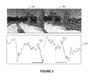
- FIGURE 3 illustrates vector projections of images for arranging a plurality of images in a sequence, in accordance with an embodiment.
- the vector projections are configured to facilitate determination of the first plurality of edge pairs between a set of first-side edge portions and a set of second-side edge portions associated with a plurality of images.
- the plurality of images may include a first image 302 and a second image 304 such that the first image 302 and the second image 304 may comprise a common portion or an matching region between them.
- a right-edge portion of the first image overlaps with a left-edge end portion of the second image.
- the vector projections 310 of the first image 302 and the second image 304 are illustrated in FIGURE 3 . As illustrated, the vector projection of the overlapping portion between the first image and the second image are similar. For example, vector projections illustrated by regions 312 and 314 corresponds to an overlap region between the first image 302 and the second image 304. It is noted that the region 312 and 314 corresponds to the right side edge portion and the left side edge portion of images 302 and 304, respectively.
- the vector projections of the images of the plurality of image may be matched for determining an overlapping region between the plurality of images.
- the vector projections of the edge pairs comprising one edge portion associated with the set of the first-side edge portions and another edge portion associated with the set of the second-side edge portions, may be matched.
- the matching of the vector projections is performed to determine a first plurality of edge pairs between the set of first-side edge portions and the set of second-side edge portions.
- the matching of the vector projections may be performed based on a NCC of the first plurality of edge pair.
- the NCC is utilized as a similarity measure in determining a matching or overlapping between various images associated with a sequence. The NCC gives an approximate matching between the first plurality of edge pairs.
- the ordering of the plurality of images based on determination of the first plurality of edge pairs is explained in detail with reference to FIGURE 5A and 5B .
- FIGURES 4A and 4B illustrate bipartite graph matching for aligning edges of a plurality of images for arranging images in a sequence, in accordance with an embodiment.
- FIGURE 4A illustrates bipartite graph matching for generating a 360 degree panorama image
- FIGURE 4B illustrates bipartite graph matching for generating a non 360 degree panorama image.
- the plurality of images may be unordered and may have to be arranged in a sequence, for example, a sequence of capture of images before being utilized for generating the panorama image.
- the plurality of images may be arranged in a sequence by utilizing the bipartite graph matching method.
- a set of first-side edge portions and a set of side-side edge portions associated with the plurality of images may be determined.
- the first-side edge portions and the second-side edge portions may comprise left side edge portions and the right-side edge portions of the plurality of images.
- the plurality of images may be arranged in a sequence to generate a one-dimensional horizontal panorama image.
- the first-side edge portions and the second-side edge portions may comprise upper-side edge portions and the lower-side edge portions of the plurality of images.
- the plurality of images may be arranged in a sequence to generate a one-dimensional vertical panorama image.
- the set of first-side edge portions may comprise for example, first-side edge portions 412, 414, 416, 418, and 420.
- the set of second-side edge portions for the plurality of images may comprise the second-side edge portions 422, 424, 426, 428, and 430.
- the bipartite graph for the plurality of images 410 comprises a first plurality of nodes and a second plurality of nodes representing the first-side edge portions 412, 414, 416, 418, 420 and the second-side edge portions 422, 424, 426, 428, and 430, and a plurality of edge portions 432, 434, 436, 438, and the like connecting the set of first-side edge portions 412, 414, 416, 418, 420 and the set of second-side edge portions 422, 424, 426, 428, and 430.
- each left-side edge portion is connected to each of the set of the right-side edge portion, and each of the first-side edge portion is connected to each of the set of the second-side edge portion by means of edge portions.
- the left side edge portion is connected to the set of right side edge portions by means of edge portions.
- the right side edge portion is connected to all other left side edge portions.
- each of the first plurality of edge pairs connecting the set of first side edge portions with the second side edge portions may be assigned a weight based on an amount of matching between the two edge portions (a first side edge portion and a second side edge portion) forming the edge pairs.
- the edge pair associated with a maximum matching may be assigned a minimum weight. It should be noted that an edge pair comprising the first side edge portion and the second side edge portion of the same image may be assigned a maximum or infinite weight.
- the plurality of images 450 may be associated with a non 360 degrees panorama image.
- the bipartite graph for the plurality of images 450 comprises a first plurality of nodes and a second plurality of nodes representing the first-side edge portions 452, 454, 456, 458 and the second-side edge portions 462, 464, 466, and 468, and a plurality of edge portions 472, 474, 476, 478, and the like connecting the set of first-side edge portions 452, 454, 456, and 458 and the set of second-side edge portions 462, 464, 466, and 468.
- the first plurality of edge pairs comprises additional edge pair associated with the peripheral images of the sequence of images, for example, additional edge pairs 460, 470, such that the additional peripheral edge portions may not find suitable match/overlap region with any of the other edge portions.
- additional edge pairs 460, 470 An example of the non-overlapping edge portions associated with a non-360 degree panorama image is illustrated in FIGURES 5A and 5B .
- the first set of weights assigned to the plurality of edge pairs may be arranged in form of a matrix.
- the dimensions of the matrix may be NXN, wherein the rows and columns of the matrix may be associated with the first side edge portions and the second side edge portions, and elements of the matrix may comprise first set of weights indicative of matching between the first-side edge portions and the second-side edge portions.
- the ordering of the plurality of images may be determined by solving the matrix for a robust weighted match of edge pairs in the bipartite graph.
- the weighted bipartite graph may be solved by utilizing the Hungarian algorithm.
- the Hungarian algorithm may be implemented with a complexity of O(N 3 ). The Hungarian algorithm may be utilized for solving the bipartite matching to generate a correct ordering of images in a sequence.
- the bipartite graph is modified to include an additional or a dummy first-side edge portion in the set of first-side edge portions and an additional or a dummy second-side edge portion in the set of second-side edge portions.
- the additional or a dummy first-side edge portion and the additional or a dummy second-side edge portion may be paired with the remaining set of the second-side edge portions and the set of the first-side edge portions, respectively to form additional plurality of edge pairs.
- the additional plurality of edge pairs may be arranged in the matrix such that the matrix may now be modified to a (N+1)X(N+1) matrix.
- the weight may be assigned to each of the elements associated with the additional edge pairs of the (N+1)X(N+1) matrix.
- the lower values of the weights assigned to the edge pairs may indicate the robust matches of the edge pairs for every first and second edge portions.
- the values of Min_i_first indicate the robust match for the first edge pairs
- the value of Min_i_second indicate the robust match for the second edge pairs.
- the values of Max_first indicate the weak match for the first edge pairs
- the values of Max_second indicate the weak match for the second edge pairs.
- the weight to be assigned to the existing first set of nodes and the second set of nodes may be defined as a difference of the weight (represented as M) of worst of all the possible robust matches and, M indicates the weight of the weakest of all possible robust matches and the value of the respective minimum edge pair.
- the weights of an existing first side edge portion or second side edge portion to the dummy first or second side edge portion is inversely proportional to the weight of a robust match. In other words, if the least cost of matching a right image edge to all available left image edges is high, the cost of its matching the background dummy node is low, and vice versa.
- the correct sequence of the plurality of images may then be similarly extracted using the Hungarian algorithm for bipartite graph matching.
- FIGURES 5A and 5B illustrates a plurality of images and a first plurality of edge pairs associated with the plurality of images, in accordance with an embodiment.
- the plurality of images includes images, for example, images 502, 504, 506, 508, 510.
- the plurality of images may be unordered, and it may be required to order the images in a sequence before being utilized for generating a panorama image.
- the term 'sequence' may be construed as an arrangement of the images in an order of capture of the images.
- the images 502, 504, 506, 508, 510 may be captured successively.
- the images 502, 504, 506, 508, 510 may be stored in a random manner, so 'arranging the images in a sequence' may be construed as placing/positioning the images in an order of capture of the images.
- placing the images in the sequence may be configured to construct a wide-angle image of the scene.
- the plurality of images may be stored in a memory, for example, the memory 204 of a device, for example, the device 200.
- the plurality of images may be received from external storage medium such as DVD, Compact Disk (CD), flash drive, memory card, or received from external storage locations through the Internet, Bluetooth ® , local area network, and the like.
- each of the plurality of images 502, 504, 506, 508, 510 may include a left-edge portion and a right-edge portion such that a right-edge portion of one image may overlap with at least a left edge portion of another image of the plurality of images.
- the unordered plurality of images 502, 504, 506, 508, 510 may be ordered at least in parts and under certain circumstances automatically.
- the plurality of images may be ordered in a sequence of, for example capture of the images to construct a panorama image by assigning a first set of weight to various edge pairs of the plurality of images 502, 504, 506, 508, 510, and arranging the plurality of images 502, 504, 506, 508, 510 in a sequence or order.
- Methods for arranging the plurality of images in a sequence is explained in FIGURES 7 and 8 .
- FIGURES 6A and 6B illustrate a plurality of images that may be ordered in a sequence for generating a 360 degree panorama image.
- the plurality of images 610 may initially be arranged in an unordered sequence.
- the plurality of images may be unordered, and may be ordered in a sequence before being utilized for generating a panorama image.
- the unordered plurality of images may be ordered at least in parts and under certain circumstances automatically, as explained with reference to FIGURE 4A .
- the plurality of unordered images, as illustrated in FIGURE 6A may be ordered, and arranged in a sequence of images such images 620, as illustrated in FIGURE 6B .
- the plurality of images ordered in a sequence may be utilized to generate a panorama image, for example a 360 degree panorama image.
- the plurality of images are associated with a rotation of an image capturing device in a horizontal direction, for example, from left to right or from right to left.
- the plurality of image may be associated with a rotation of the image capturing device in a vertical direction for example, from top to bottom or from bottom to top.
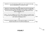
- FIGURE 7 is a flowchart depicting an example method 700 for arranging a plurality of images in a sequence, in accordance with an example embodiment.
- the method depicted in the flow chart may be executed by, for example, the apparatus 200 of FIGURE 2 .
- the plurality of images may be associated with a scene, and may be unordered.
- the plurality of images may be ordered arranged in the sequence based on a determination of an matching between the edge portions of plurality of images.
- each of the plurality of images may include a first-side edge portion and a second-side edge portion such that the first-side edge portion is opposite to the second-side edge portion.
- the first-side edge portion may comprise a left side edge portion and the second-side edge portion may comprise a right side edge portion, and vice-versa.
- the first-side edge portion may comprise a top-side edge portion and the second-side edge portion may comprise a bottom-side edge portion, and vice-versa.
- determining the set of first-side edge portions and the set of second-side edge portions comprises determining vertical projections of the plurality of images, and matching the vertical projections for determining a matching between the edge portions associated with the set of first-side edge portions and the set of second-side edge portions.
- a left side edge portion of a first image may comprise a matching region that may be common with a right-side edge portion of a second image.
- a top-side edge portion of an image may include a portion that may be common with a bottom-side edge portion of a second image.
- a first plurality of edge pairs between the set of first-side edge portions and the set of second-side edge portions is determined.
- an edge pair of the first plurality of edge pairs comprises a first-side edge portion of one image and a second-side edge portion of another image of the plurality of images.
- the first plurality of edge pairs is determined based on a matching between the set of first side edge portions and the set of second side edge portions.
- the first plurality of edge pairs may be determined by matching the vector projections of each of the set of first-side edge portions with each of the set of second-side edge portions to determine a pair-wise matching between each edge pair of the first plurality of edge pairs.
- the vector projections associated with the set of the first-side edge portions and the set of the second-side edge portions may be matched based on a normalized cross correlation of the first plurality of edge pairs.
- a first set of weights may be assigned to the first plurality edge pairs based at least on the pair-wise matching between the set of first-side edge portions and the set of second-side edge portions.
- the weights may be assigned to the first plurality edge pairs by computing EOG on an overlapping area between the edge portions associated with the plurality of edge pairs images.
- a distance may be computed between the EOG of the edge portions associated with the edge pairs, and based on the distance, a weight may be assigned to the edge pair of the plurality of edge pairs.
- the distance may be a Bhattacharyya distance.
- 'Bhattacharyya distance' refers to a coefficient that may be indicative of an overlap between the two edge portions associated with an edge pair.
- the pair-wise matching between the set of first-side edge portions and the set of second-side edge portions is performed based on by computing the EOG on the overlapping area, and determining the Bhattacharyya distance.
- the pair-wise matching between the portions of images may be performed by a variety of other methods other than EOG that are configured to determine histograms, for example, Histogram of Gradients (HOG), integral projections (horizontal projections for left-right panorama images, and vertical projections for top-bottom panorama images), Local binary pattern histogram (LBP), and the like.
- HOG Histogram of Gradients
- integral projections horizontal projections for left-right panorama images, and vertical projections for top-bottom panorama images
- LBP Local binary pattern histogram
- various other methods may be utilized for determination of distance between histograms or distributions, such as, a cost of dynamic time warping technique (with integral projections as features), cosine distance technique (with LBP histograms), and the like.
- the first set of weights may be arranged in form of matrix, as explained with reference to FIGURE 2 .
- the dimensions of the matrix may be NXN.
- the plurality of images may be associated with a 360 degree panorama.
- plurality of images may be associated with a non-360.
- the non-360 degree panorama may include two peripheral images, for example a left peripheral image and a right peripheral image (in case of a horizontal 1-D panorama image) such that the peripheral edge portions of the two peripheral images may not have a common overlapping portion with either of the edge portions of the remaining images.
- the weights may be assigned by determining two dummy edge portions, for example, a dummy first-side edge portion and a dummy second-side edge portion associated with the first peripheral image and the second peripheral image, respectively.
- the dummy first-side edge portion and the dummy second-side edge portion are determined based on the first set of weights assigned to the first set of plurality of edge pairs.
- the first set of weights may be compared with a predetermined threshold weight.
- the predetermined threshold weight may be indicative of poor matching between the set of the first-side edge portions and the set of second-side edge portions.
- the weights greater than the predetermined threshold weight may be indicative of edge portion that may have nil matching between them, for example the extreme edge portions of the peripheral images of a sequence of images.
- the first set of weights may be assigned to the first plurality of edge pairs by generating a bipartite graph between the set of first-side edge portions and a set of second-side edge portions and connecting the set of first-side edge portions and the set of second-side edge portions by the first plurality of edge pairs.
- the first set of weight may be assigned to the first plurality of edge pairs based on a pair-wise matching between the edge portions comprising the edge pair.
- the plurality of images may be arranged in a first sequence based on the weights assigned to the first plurality of edge pairs.
- arranging the plurality of images in the first sequence facilitates in generating a panorama image.
- the plurality of images may be arranged in the first sequence and stitched in that sequence to generate the panorama image.
- a processing means may be configured to perform some or all of: determining a set of first-side edge portions and a set of second-side edge portions associated with a plurality of images, the set of the first-side edge portions being opposite to the set of the second-side edge portions; determining a first plurality of edge pairs between the set of first-side edge portions and the set of second-side edge portions, an edge pair of the first plurality of edge pair comprising a first-side edge portion and a second-side edge portion; assigning a first set of weights to the first plurality of edge pairs based at least on a pair-wise matching between the set of first-side edge portions and the set of second-side edge portions; and arranging the plurality of images in a sequence based on the first set of weights assigned to the first plurality of edge pairs.
- An example of the processing means may include the processor 202, which may be an example of the controller 108. Another method for arranging the plurality of images in a sequence is explained in detail with reference to FIGURE 8
- FIGURES 8A and 8B illustrate a flowchart depicting an example method 800 for arranging images in a sequence, in accordance with another example embodiment.
- the method 800 depicted in flow chart may be executed by, for example, the apparatus 200 of FIGURE 2 .
- Operations of the flowchart, and combinations of operation in the flowchart may be implemented by various means, such as hardware, firmware, processor, circuitry and/or other device associated with execution of software including one or more computer program instructions.
- one or more of the procedures described in various embodiments may be embodied by computer program instructions.
- the computer program instructions, which embody the procedures, described in various embodiments may be stored by at least one memory device of an apparatus and executed by at least one processor in the apparatus.
- Any such computer program instructions may be loaded onto a computer or other programmable apparatus (for example, hardware) to produce a machine, such that the resulting computer or other programmable apparatus embody means for implementing the operations specified in the flowchart.
- These computer program instructions may also be stored in a computer-readable storage memory (as opposed to a transmission medium such as a carrier wave or electromagnetic signal) that may direct a computer or other programmable apparatus to function in a particular manner, such that the instructions stored in the computer-readable memory produce an article of manufacture the execution of which implements the operations specified in the flowchart.
- the computer program instructions may also be loaded onto a computer or other programmable apparatus to cause a series of operations to be performed on the computer or other programmable apparatus to produce a computer-implemented process such that the instructions, which execute on the computer or other programmable apparatus provide operations for implementing the operations in the flowchart.
- the operations of the method 800 are described with help of apparatus 200. However, the operations of the method can be described and/or practiced by using any other apparatus.
- the method for arranging the plurality of images is initiated at block 802.
- receiving of a plurality of images is facilitated.
- the plurality of images may be pre-recorded and stored in the apparatus 200.
- the plurality of images may be captured by utilizing a camera module, for example the camera module 122 of a device, for example the device 100, and stored in the memory of the device 100.
- the device may receive the plurality of images from an internal memory such as hard drive, RAM of an apparatus, for example the apparatus 200, or from external storage medium such as DVD, CD, flash drive, memory card, or from external storage locations through Internet, Bluetooth ® , and the like.
- the apparatus may also receive the plurality of images from the memory thereof.
- each of the plurality of images may include a first-side edge portion and a second-side edge portion such that the first-side edge portion is opposite to the second-side edge portion.
- the first-side edge portion and the second-side edge portion may include a left side edge portion and a right side edge portion, respectively of an image or vice-versa.
- the first-side edge portion and the second-side edge portion may include a topside edge portion and a bottom side edge portion, respectively of an image or vice-versa.
- the images associated with the plurality of images may include certain overlapping portions.
- a first side edge portion of one image may overlap with a second side edge portion of another image.
- vector projections of the set of first-side edge portions and the set of second-side edge portions may be determined.
- the determination of the vector projections of the set of first-side edge portions and the set of second-side edge portions is already explained with respect to FIGURE 3 .
- the two images may be determined to adjacent images and comprise of an overlapping portion between them.
- the vector projections of each of the set of first-side edge portions is matched with the vector projections of each of the set of second-side edge portions to determine a pair-wise matching between each edge pair of a first plurality of edge pairs.
- the pair-wise matching between the first plurality of edge pairs may be determined by computing the histograms or distributions of the edge portions of the plurality of images, and measuring distance between the corresponding histograms.
- the histograms associated with the plurality of images may be computed by using techniques, such as EOG, HOG, integral projections, LBP, and the like.
- the distance between the histograms may be computed by utilizing techniques, such as cost of dynamic time warping (with integral projections as features), cosine distance (with LBP histograms), and the like.
- At least one of the edge portions of the first set of edge portions and the second set of edge portions may not be matched with any of the edge portions.
- the non-overlapping opposite edge portions thereof such as first-side edge portion of the first peripheral image and the second-side edge portion of the second peripheral image, may be determined by assuming a dummy first-side edge portion and a dummy second-side edge portion.
- the dummy first-side edge portion and the dummy-second side edge portion may be associated with a relatively high weight because of existence of high non-overlapping between the dummy-first side edge portion and the second-side edge portions, and between the dummy-second side edge portion and the first-side edge portions.
- the dummy edge portions may be determined for the case wherein the plurality of images are associated with a non-360 degrees view of a scene. Examples of such images may include a one dimensional non-360 degrees panorama image, a two dimensional non-360 degrees panorama image, and the like.
- a first set of weights may be assigned to the first plurality of edge pairs based at least on a pair-wise matching between the set of first-side edge portions and the set of second-side edge portions.
- the weights assigned to the plurality of edge pairs may be represented in form of a NXN matrix.
- the dimensions of the matrix are associated with a number of first-side edge portions and a number of second-side edge portions of the plurality of images.
- the plurality of images (N) associated with a 360 degree panorama image the dimensions of a matrix may be NXN.
- the dimensions of a matrix corresponding to N images may be (N+1)X(N+1).
- an additional node in the matrix of weights corresponding to non-360 degrees panorama image is associated with the additional dummy nodes being determined.
- the weights to the dummy edge portions may be assigned in a manner that the weight of the edge pair having a dummy edge portion is inversely proportional to the weight of its robust match. In other words, if the least weight of any edge pair comprising a right-side edge portion to all the available left-side edge portion is high, then the weight associated with the edge pair having a dummy edge portion is low, and vice versa.
- the plurality of images may be arranged in a first sequence based on the first set of weights assigned to the first plurality of edge pairs.
- the plurality of images are arranged in the first sequence by selecting, for each row of the matrix, an edge pair between the set of first-side edge portions and the set of second-side edge portions that is associated with a minimum weight.
- the minimum weight is associated with the maximum pair-wise matching.
- the first sequence of images may be configured to generate a panorama image.
- the first sequence of images may be configured to generate a one dimensional panorama image.
- the first sequence of images may be configured to generate a 360 degree panorama image.
- the 360 degree panorama image may refer to a panorama image being generated by rotating and capturing a wide range image around a scene wherein the first end of the image is logically connected to the second end of another image. Accordingly, the first-side edge portion of the first peripheral image is connected to the second-side edge portion of the second peripheral image.
- a non-360 degree panorama image may be a 180 degree panorama image, wherein the sequence comprises plurality of images arranged in a manner that the first left-side edge portion of the left most image and the right-side edge portion of the right most image of the sequence of images have substantially nothing in common.
- the first sequence of images may be associated with a 360 degree panorama image.
- the first sequence of images may be generated based on a determination of weights associated with the first set of weights. In an embodiment, it is determined at block 816, whether weights associated with the first set of weights is greater or equal to a predetermined threshold weight. If it is determined at block 816 that a plurality of weights are less than the predetermined threshold weight, then it may be determined that the first sequence of images is associated with a 360 degrees image, and the method may be terminated at block 818.
- the first sequence may be split into a plurality of sub-sequences based on the edge pairs having weights greater than the predetermined threshold weight.
- the first sequence of images may include images I1, I2, I3, I4, I5, I6 I7, I8, and I9, and the weights associated with the edge pairs such as right edge of image I3 and left edge of image I4, and right edge of image I6 and left edge of image I7 are greater than the predetermined threshold weight, then the first image sequence may be split at the edge pairs (I3-I4) and (I6-I7).
- the splitting of the first sequence may generate a plurality of sub-sequences.
- the splitting of the first sequence (I1, I2, I3, I4, I5, I6 I7, I8, I9) at the edge pairs (I3-I4) and (I6-I7) may generate a plurality of sub-sequences S1(I1, I2, I3), S2(I4, I5, I6), and S3(I7, I8, I9).
- each of the plurality of sub-sequences may be equivalent to images, such as one dimensional image.
- a set of third-side edge portions and a set of fourth-side edge portions associated with the plurality of sub-sequences may be determined.
- the set of the third-side edge portions may be opposite to the set of the fourth-side edge portions.
- the set of third-side edge portion and the fourth-side portions of the sub-sequences may include top and bottom side edge portions of the sub-sequences.
- the set of third-side edge portion and the fourth-side portions of the sub-sequences may include left and right side edge portions of the sub-sequences. It will be understood that various variations of the arrangement of the third-side edge portions and the fourth-side edge portions of the sub-sequences may be possible.
- a second plurality of edge pairs between the set of third-side edge portions and the set of fourth-side edge portions may be determined.
- an edge pair of the second plurality of edge pairs comprises a third-side edge portion and a fourth-side edge portion.
- the second plurality of edge pair may be determined by determining bipartite graph between the set of third-side edge portions and the set of fourth-side edge portions.
- the bipartite graph comprises a plurality of nodes and a plurality of edges such that the plurality of edges connects every node to every other node.
- the plurality of nodes comprises a first set of nodes representing the set of third-side edge portions and second set of nodes representing the set of fourth-side edge portions of the plurality of images.
- the representation of the example edge portions as nodes, and example edges connecting the example nodes in form of a bipartite graph is explained in detail with reference to FIGURES 4A and 4B .
- FIGURE 4A represent bipartite graph for the case of a 360 degrees panorama image
- FIGURE 4B represent bipartite graph for the case of a non 360 degrees panorama image.
- a second set of weights is assigned to the second plurality of edge pairs based on a pair-wise matching between the set of third-side edge portions and the set of fourth-side edge portions.
- the second set of weights may be assigned by determining histograms associated with the third-side edge portion and the fourth-side edge portion associated with the each edge pair of the second plurality of edge pairs, and computing a distance between the histograms.
- the distance is indicative of the weight associated with the edge pair.
- the pair-wise matching between the set of third-side edge portions and the set of fourth-side edge portions is performed by computing the EOG on the overlapping area, and determining the Bhattacharyya distance.
- the pair-wise matching between the portions of images may be performed by a variety of other methods other than EOG that are configured to determine histograms, for example, HOG, Integral projections (for example, horizontal projections for left-right image sequence and vertical projection for top-bottom image sequence), LBP, and the like.
- various other methods may be utilized for determination of distance between histograms or distributions, such as, a cost of dynamic time warping technique (with integral projections as features), cosine distance technique (with LBP histograms), and the like.
- the plurality of images may be arranged in a second sequence based on the weights assigned to the second plurality of edge pairs.
- the weights assigned to the edge pairs between the sub-sequences S1-S2, S2-S3 and S3-S1 may be in an order of W1, W2, and W3 such that W1 is equal to W2 while W3 is relatively much higher.
- the sub-sequences may be arranged in a second sequence, wherein S1 is followed by S2, and S2 is followed by S3.
- the second sequence of images may facilitate in generation of a two dimensional panorama image.
- a two dimensional panorama image may be generated, for instance by stitching the plurality of images arranged in the second sequence.
- the method for arranging the plurality of images in a sequence, for example the first sequence and the second sequence may be terminated at block 818.
- Certain operations are described herein as constituting distinct steps performed in a certain order. Such implementations are exemplary and nonlimiting. Certain operation may be grouped together and performed in a single operation, and certain operations can be performed in an order that differs from the order employed in the examples set forth herein. Moreover, certain operations of the method 800 are performed in an automated fashion. These operations involve substantially no interaction with the user. Other operations of the method 800 may be performed by in a manual fashion or semi-automatic fashion. These operations involve interaction with the user via one or more user interface presentations.
- a technical effect of one or more of the example embodiments disclosed herein is to arrange a plurality of images associated with a scene in a sequence.
- the plurality of images may be associated with one of a 360 degrees panorama and a non-360 degrees panorama image.
- the plurality of images may be arranged in a sequence by determining and overlap between the plurality of images, and a weight may be assigned to each of the overlapping edge pairs.
- the plurality of images may be arranged in the sequence based on the assigned weight.
- the disclosed method is performed at least in parts and under certain circumstances automatically after the capture of the images. Accordingly, while arranging the plurality of images in the sequence, no user interaction is required.
- the disclosed method facilitates in arranging the plurality of images associated with a 360 degree panorama image as well as with a non-360 degree panorama image.
- Various embodiments described above may be implemented in software, hardware, application logic or a combination of software, hardware and application logic.
- the software, application logic and/or hardware may reside on at least one memory, at least one processor, an apparatus or, a computer program product.
- the application logic, software or an instruction set is maintained on any one of various conventional computer-readable media.
- a "computer-readable medium" may be any media or means that can contain, store, communicate, propagate or transport the instructions for use by or in connection with an instruction execution system, apparatus, or device, such as a computer, with one example of an apparatus described and depicted in FIGURES 1 and/or 2.
- a computer-readable medium may comprise a computer-readable storage medium that may be any media or means that can contain or store the instructions for use by or in connection with an instruction execution system, apparatus, or device, such as a computer.
- the different functions discussed herein may be performed in a different order and/or concurrently with each other. Furthermore, if desired, one or more of the above-described functions may be optional or may be combined.
Applications Claiming Priority (1)
| Application Number | Priority Date | Filing Date | Title |
|---|---|---|---|
| IN2575CH2012 | 2012-06-28 |
Publications (1)
| Publication Number | Publication Date |
|---|---|
| EP2680222A1 true EP2680222A1 (de) | 2014-01-01 |
Family
ID=48745723
Family Applications (1)
| Application Number | Title | Priority Date | Filing Date |
|---|---|---|---|
| EP13173908.8A Withdrawn EP2680222A1 (de) | 2012-06-28 | 2013-06-27 | Verfahren, Vorrichtung und Computerprogrammprodukt zur Verarbeitung von Medieninhalten |
Country Status (2)
| Country | Link |
|---|---|
| US (1) | US20140152762A1 (de) |
| EP (1) | EP2680222A1 (de) |
Cited By (1)
| Publication number | Priority date | Publication date | Assignee | Title |
|---|---|---|---|---|
| CN106447649A (zh) * | 2016-08-25 | 2017-02-22 | 凌云光技术集团有限责任公司 | 一种珠体位置缺陷检测方法及装置 |
Families Citing this family (36)
| Publication number | Priority date | Publication date | Assignee | Title |
|---|---|---|---|---|
| US9185387B2 (en) | 2012-07-03 | 2015-11-10 | Gopro, Inc. | Image blur based on 3D depth information |
| US9076238B2 (en) * | 2013-08-21 | 2015-07-07 | Seiko Epson Corporation | Intelligent weighted blending for ultrasound image stitching |
| US9685194B2 (en) | 2014-07-23 | 2017-06-20 | Gopro, Inc. | Voice-based video tagging |
| US9792502B2 (en) | 2014-07-23 | 2017-10-17 | Gopro, Inc. | Generating video summaries for a video using video summary templates |
| US9734870B2 (en) | 2015-01-05 | 2017-08-15 | Gopro, Inc. | Media identifier generation for camera-captured media |
| US9483706B2 (en) * | 2015-01-08 | 2016-11-01 | Linear Algebra Technologies Limited | Hardware accelerator for histogram of gradients |
| US10277906B2 (en) * | 2015-03-23 | 2019-04-30 | Arris Enterprises Llc | System and method for selectively compressing images |
| US9639560B1 (en) | 2015-10-22 | 2017-05-02 | Gopro, Inc. | Systems and methods that effectuate transmission of workflow between computing platforms |
| US9787862B1 (en) | 2016-01-19 | 2017-10-10 | Gopro, Inc. | Apparatus and methods for generating content proxy |
| US10078644B1 (en) | 2016-01-19 | 2018-09-18 | Gopro, Inc. | Apparatus and methods for manipulating multicamera content using content proxy |
| US9871994B1 (en) | 2016-01-19 | 2018-01-16 | Gopro, Inc. | Apparatus and methods for providing content context using session metadata |
| US10129464B1 (en) | 2016-02-18 | 2018-11-13 | Gopro, Inc. | User interface for creating composite images |
| US9972066B1 (en) | 2016-03-16 | 2018-05-15 | Gopro, Inc. | Systems and methods for providing variable image projection for spherical visual content |
| US10402938B1 (en) | 2016-03-31 | 2019-09-03 | Gopro, Inc. | Systems and methods for modifying image distortion (curvature) for viewing distance in post capture |
| US9838730B1 (en) | 2016-04-07 | 2017-12-05 | Gopro, Inc. | Systems and methods for audio track selection in video editing |
| US10229719B1 (en) | 2016-05-09 | 2019-03-12 | Gopro, Inc. | Systems and methods for generating highlights for a video |
| US9953679B1 (en) | 2016-05-24 | 2018-04-24 | Gopro, Inc. | Systems and methods for generating a time lapse video |
| US9922682B1 (en) | 2016-06-15 | 2018-03-20 | Gopro, Inc. | Systems and methods for organizing video files |
| US9967515B1 (en) | 2016-06-15 | 2018-05-08 | Gopro, Inc. | Systems and methods for bidirectional speed ramping |
| US10045120B2 (en) | 2016-06-20 | 2018-08-07 | Gopro, Inc. | Associating audio with three-dimensional objects in videos |
| US10395119B1 (en) | 2016-08-10 | 2019-08-27 | Gopro, Inc. | Systems and methods for determining activities performed during video capture |
| US9953224B1 (en) | 2016-08-23 | 2018-04-24 | Gopro, Inc. | Systems and methods for generating a video summary |
| US10268898B1 (en) | 2016-09-21 | 2019-04-23 | Gopro, Inc. | Systems and methods for determining a sample frame order for analyzing a video via segments |
| US10282632B1 (en) | 2016-09-21 | 2019-05-07 | Gopro, Inc. | Systems and methods for determining a sample frame order for analyzing a video |
| US10397415B1 (en) | 2016-09-30 | 2019-08-27 | Gopro, Inc. | Systems and methods for automatically transferring audiovisual content |
| US10044972B1 (en) | 2016-09-30 | 2018-08-07 | Gopro, Inc. | Systems and methods for automatically transferring audiovisual content |
| US11106988B2 (en) | 2016-10-06 | 2021-08-31 | Gopro, Inc. | Systems and methods for determining predicted risk for a flight path of an unmanned aerial vehicle |
| US10002641B1 (en) | 2016-10-17 | 2018-06-19 | Gopro, Inc. | Systems and methods for determining highlight segment sets |
| US10339443B1 (en) | 2017-02-24 | 2019-07-02 | Gopro, Inc. | Systems and methods for processing convolutional neural network operations using textures |
| US9916863B1 (en) | 2017-02-24 | 2018-03-13 | Gopro, Inc. | Systems and methods for editing videos based on shakiness measures |
| US10360663B1 (en) | 2017-04-07 | 2019-07-23 | Gopro, Inc. | Systems and methods to create a dynamic blur effect in visual content |
| US10395122B1 (en) | 2017-05-12 | 2019-08-27 | Gopro, Inc. | Systems and methods for identifying moments in videos |
| US10614114B1 (en) | 2017-07-10 | 2020-04-07 | Gopro, Inc. | Systems and methods for creating compilations based on hierarchical clustering |
| US10402698B1 (en) | 2017-07-10 | 2019-09-03 | Gopro, Inc. | Systems and methods for identifying interesting moments within videos |
| CN108492327B (zh) * | 2018-02-07 | 2021-01-26 | 广州视源电子科技股份有限公司 | Aoi图像匹配方法、系统、可读存储介质及智能设备 |
| US10628698B1 (en) * | 2019-07-02 | 2020-04-21 | Grundium Oy | Method for image stitching |
Citations (3)
| Publication number | Priority date | Publication date | Assignee | Title |
|---|---|---|---|---|
| US20050094898A1 (en) * | 2003-09-22 | 2005-05-05 | Chenyang Xu | Method and system for hybrid rigid registration of 2D/3D medical images |
| US20120019614A1 (en) * | 2009-12-11 | 2012-01-26 | Tessera Technologies Ireland Limited | Variable Stereo Base for (3D) Panorama Creation on Handheld Device |
| WO2012039719A1 (en) * | 2010-09-24 | 2012-03-29 | Hewlett-Packard Development Company, L.P. | Image registration |
Family Cites Families (5)
| Publication number | Priority date | Publication date | Assignee | Title |
|---|---|---|---|---|
| JP3432736B2 (ja) * | 1997-10-29 | 2003-08-04 | シャープ株式会社 | 画像処理装置 |
| US20070200926A1 (en) * | 2006-02-28 | 2007-08-30 | Chianglin Yi T | Apparatus and method for generating panorama images |
| DE102007019057A1 (de) * | 2007-04-23 | 2008-10-30 | Fraunhofer-Gesellschaft zur Förderung der angewandten Forschung e.V. | Vorrichtung und Verfahren zum Bestimmen eines Kanten-Histogramms, Vorrichtung und Verfahren zum Ablegen eines Bildes in einer Bilddatenbank, Vorrichtung und Verfahren zum Auffinden von zwei ähnlichen Bildern und Computerprogramm |
| KR100866278B1 (ko) * | 2007-04-26 | 2008-10-31 | 주식회사 코아로직 | 파노라마 영상 생성 장치, 방법 및 상기 방법을프로그램화하여 수록한 컴퓨터로 읽을 수 있는 기록매체 |
| JP5878295B2 (ja) * | 2011-01-13 | 2016-03-08 | ソニー株式会社 | 画像処理装置、画像処理方法およびプログラム |
-
2013
- 2013-06-27 US US13/928,727 patent/US20140152762A1/en not_active Abandoned
- 2013-06-27 EP EP13173908.8A patent/EP2680222A1/de not_active Withdrawn
Patent Citations (3)
| Publication number | Priority date | Publication date | Assignee | Title |
|---|---|---|---|---|
| US20050094898A1 (en) * | 2003-09-22 | 2005-05-05 | Chenyang Xu | Method and system for hybrid rigid registration of 2D/3D medical images |
| US20120019614A1 (en) * | 2009-12-11 | 2012-01-26 | Tessera Technologies Ireland Limited | Variable Stereo Base for (3D) Panorama Creation on Handheld Device |
| WO2012039719A1 (en) * | 2010-09-24 | 2012-03-29 | Hewlett-Packard Development Company, L.P. | Image registration |
Non-Patent Citations (3)
| Title |
|---|
| BROWN ET AL: "Recognising panoramas", PROCEEDINGS OF THE EIGHT IEEE INTERNATIONAL CONFERENCE ON COMPUTER VISION. (ICCV). NICE, FRANCE, OCT. 13 - 16, 2003; [INTERNATIONAL CONFERENCE ON COMPUTER VISION], LOS ALAMITOS, CA : IEEE COMP. SOC, US, 13 October 2003 (2003-10-13), pages 1218 - 1225, XP031213183, ISBN: 978-0-7695-1950-0 * |
| LIHI ZELNIK-MANOR ET AL: "Automating joiners", PROCEEDINGS OF THE 5TH INTERNATIONAL SYMPOSIUM ON NON-PHOTOREALISTIC ANIMATION AND RENDERING, NPAR '07, 1 January 2007 (2007-01-01), New York, New York, USA, pages 121, XP055080809, ISBN: 978-1-59-593624-0, DOI: 10.1145/1274871.1274890 * |
| SIBIRYAKOV A ET AL: "Graph-based multiple panorama extraction from unordered image sets", PROCEEDINGS OF THE SPIE - THE INTERNATIONAL SOCIETY FOR OPTICAL ENGINEERING SPIE - THE INTERNATIONAL SOCIETY FOR OPTICAL ENGINEERING USA, vol. 6498, 2007, pages 649809 - 1, XP040236519, ISSN: 0277-786X * |
Cited By (2)
| Publication number | Priority date | Publication date | Assignee | Title |
|---|---|---|---|---|
| CN106447649A (zh) * | 2016-08-25 | 2017-02-22 | 凌云光技术集团有限责任公司 | 一种珠体位置缺陷检测方法及装置 |
| CN106447649B (zh) * | 2016-08-25 | 2019-03-29 | 凌云光技术集团有限责任公司 | 一种珠体位置缺陷检测方法及装置 |
Also Published As
| Publication number | Publication date |
|---|---|
| US20140152762A1 (en) | 2014-06-05 |
Similar Documents
| Publication | Publication Date | Title |
|---|---|---|
| EP2680222A1 (de) | Verfahren, Vorrichtung und Computerprogrammprodukt zur Verarbeitung von Medieninhalten | |
| US9542750B2 (en) | Method, apparatus and computer program product for depth estimation of stereo images | |
| US9443130B2 (en) | Method, apparatus and computer program product for object detection and segmentation | |
| US9342866B2 (en) | Method, apparatus and computer program product for generating panorama images | |
| US10003743B2 (en) | Method, apparatus and computer program product for image refocusing for light-field images | |
| US9390508B2 (en) | Method, apparatus and computer program product for disparity map estimation of stereo images | |
| US9245315B2 (en) | Method, apparatus and computer program product for generating super-resolved images | |
| US9153054B2 (en) | Method, apparatus and computer program product for processing of images and compression values | |
| US9349166B2 (en) | Method, apparatus and computer program product for generating images of scenes having high dynamic range | |
| US9147226B2 (en) | Method, apparatus and computer program product for processing of images | |
| US9183618B2 (en) | Method, apparatus and computer program product for alignment of frames | |
| US9412175B2 (en) | Method, apparatus and computer program product for image segmentation | |
| US9619863B2 (en) | Method, apparatus and computer program product for generating panorama images | |
| US9489741B2 (en) | Method, apparatus and computer program product for disparity estimation of foreground objects in images | |
| US9886767B2 (en) | Method, apparatus and computer program product for segmentation of objects in images | |
| US20130107008A1 (en) | Method, apparatus and computer program product for capturing images | |
| US20130342567A1 (en) | Method, apparatus and computer program product for processing of multimedia content | |
| US10097807B2 (en) | Method, apparatus and computer program product for blending multimedia content | |
| US20160180499A1 (en) | Method, apparatus and computer program product for alignment of images |
Legal Events
| Date | Code | Title | Description |
|---|---|---|---|
| PUAI | Public reference made under article 153(3) epc to a published international application that has entered the european phase |
Free format text: ORIGINAL CODE: 0009012 |
|
| AK | Designated contracting states |
Kind code of ref document: A1 Designated state(s): AL AT BE BG CH CY CZ DE DK EE ES FI FR GB GR HR HU IE IS IT LI LT LU LV MC MK MT NL NO PL PT RO RS SE SI SK SM TR |
|
| AX | Request for extension of the european patent |
Extension state: BA ME |
|
| RAP1 | Party data changed (applicant data changed or rights of an application transferred) |
Owner name: NOKIA CORPORATION |
|
| STAA | Information on the status of an ep patent application or granted ep patent |
Free format text: STATUS: THE APPLICATION IS DEEMED TO BE WITHDRAWN |
|
| 18D | Application deemed to be withdrawn |
Effective date: 20140702 |