EP2680056A1 - Optical scanning device and image forming apparatus with the same - Google Patents
Optical scanning device and image forming apparatus with the same Download PDFInfo
- Publication number
- EP2680056A1 EP2680056A1 EP20130173836 EP13173836A EP2680056A1 EP 2680056 A1 EP2680056 A1 EP 2680056A1 EP 20130173836 EP20130173836 EP 20130173836 EP 13173836 A EP13173836 A EP 13173836A EP 2680056 A1 EP2680056 A1 EP 2680056A1
- Authority
- EP
- European Patent Office
- Prior art keywords
- lens
- heat
- optical scanning
- wall
- scanning device
- Prior art date
- Legal status (The legal status is an assumption and is not a legal conclusion. Google has not performed a legal analysis and makes no representation as to the accuracy of the status listed.)
- Granted
Links
Images





Classifications
-
- G—PHYSICS
- G03—PHOTOGRAPHY; CINEMATOGRAPHY; ANALOGOUS TECHNIQUES USING WAVES OTHER THAN OPTICAL WAVES; ELECTROGRAPHY; HOLOGRAPHY
- G03G—ELECTROGRAPHY; ELECTROPHOTOGRAPHY; MAGNETOGRAPHY
- G03G15/00—Apparatus for electrographic processes using a charge pattern
- G03G15/22—Apparatus for electrographic processes using a charge pattern involving the combination of more than one step according to groups G03G13/02 - G03G13/20
- G03G15/28—Apparatus for electrographic processes using a charge pattern involving the combination of more than one step according to groups G03G13/02 - G03G13/20 in which projection is obtained by line scanning
-
- G—PHYSICS
- G02—OPTICS
- G02B—OPTICAL ELEMENTS, SYSTEMS OR APPARATUS
- G02B26/00—Optical devices or arrangements for the control of light using movable or deformable optical elements
- G02B26/08—Optical devices or arrangements for the control of light using movable or deformable optical elements for controlling the direction of light
- G02B26/10—Scanning systems
- G02B26/12—Scanning systems using multifaceted mirrors
- G02B26/125—Details of the optical system between the polygonal mirror and the image plane
-
- G—PHYSICS
- G02—OPTICS
- G02B—OPTICAL ELEMENTS, SYSTEMS OR APPARATUS
- G02B26/00—Optical devices or arrangements for the control of light using movable or deformable optical elements
- G02B26/08—Optical devices or arrangements for the control of light using movable or deformable optical elements for controlling the direction of light
- G02B26/10—Scanning systems
- G02B26/12—Scanning systems using multifaceted mirrors
-
- G—PHYSICS
- G02—OPTICS
- G02B—OPTICAL ELEMENTS, SYSTEMS OR APPARATUS
- G02B7/00—Mountings, adjusting means, or light-tight connections, for optical elements
- G02B7/008—Mountings, adjusting means, or light-tight connections, for optical elements with means for compensating for changes in temperature or for controlling the temperature; thermal stabilisation
-
- H—ELECTRICITY
- H04—ELECTRIC COMMUNICATION TECHNIQUE
- H04N—PICTORIAL COMMUNICATION, e.g. TELEVISION
- H04N1/00—Scanning, transmission or reproduction of documents or the like, e.g. facsimile transmission; Details thereof
- H04N1/00976—Arrangements for regulating environment, e.g. removing static electricity
- H04N1/00978—Temperature control
Definitions
- the present disclosure relates to an optical scanning device configured to form an electrostatic latent image on an image carrier and an image forming apparatus with the optical scanning device.
- An image forming apparatus includes an optical scanning device configured to form an electrostatic latent image on a photosensitive drum capable of carrying an image.
- An exposure device serving as the optical scanning device may include a laser diode, a lens, a polygon mirror, a polygon motor, an f ⁇ lens, and a fold mirror all of which are contained in a housing.
- Laser light emitted from the laser diode is guided through the lens to the polygon mirror. Then, the laser light incident on the polygon mirror driven into rotation by the motor is reflected and deflected by the mirror surfaces of the polygon mirror, then passes through the f ⁇ lens, and is then reflected by the fold mirror. Thus, the laser light is guided to the drum surface of the photosensitive drum rotating in a sub-scanning direction and scans the drum surface in a main scanning direction.
- heat generated from the polygon motor may be unevenly distributed in the housing to cause a temperature gradient in the f ⁇ lens and thus cause unevenness in refractive index of the f ⁇ lens.
- a thermally conductive member may be disposed between a high-temperature portion and a low-temperature portion inside the housing to make the internal temperature of the housing uniform.
- a metallic member may be disposed between a main frame of the image forming apparatus to which the exposure device is mounted and the housing of the exposure device.
- the metallic member is directly mounted to the main frame and changed in shape between the high-temperature portion and the low-temperature portion in the housing to give a difference in heat dissipation performance and thereby make the internal temperature of the housing uniform.
- an optical scanning device includes a housing, a laser light source, a polygon mirror, a polygon motor, an f ⁇ lens, and a heat-insulating room.
- the housing includes a first wall portion, a second wall portion intersecting with the first wall portion, and a housing top directly mounted on top of the first and second wall portions.
- the laser light source is configured to emit laser light.
- the polygon mirror includes a plurality of mirror surfaces and is disposed in an internal space defined by the housing.
- the polygon mirror is configured to be driven into rotation and deflect the laser light.
- the polygon motor is configured to rotate the polygon mirror so that the plurality of mirror surfaces sequentially face the first wall portion and then face the second wall portion.
- the f ⁇ lens is disposed between the polygon motor and the second wall portion to extend in a direction perpendicular to the first wall portion and is configured to refract the laser light deflected by the polygon mirror.
- the heat-insulating room is disposed in an area above a portion of the f ⁇ lens away from the first wall portion in a direction of extension of the f ⁇ lens and insulates heat radiated from the internal space.
- An image forming apparatus includes an image carrier, a charging section, an exposure section, and a developing section.
- a toner image is formed on a surface of the image carrier.
- the charging section is configured to charge the surface of the image carrier.
- the exposure section is configured to expose the surface of the image carrier charged by the charging section to light to form an electrostatic latent image on the surface of the image carrier.
- the developing section is configured to supply toner to the electrostatic latent image formed by the exposure section to form the toner image.
- the exposure section includes:
- FIG. 1 is a perspective view of a printer 100 (image forming apparatus) according to an embodiment of the present disclosure.
- FIG. 2 is a view schematically showing an internal structure of the printer 100 shown in FIG. 1 .
- the printer 100 shown in FIGS. 1 and 2 is a so-called black-and-white printer.
- the image forming apparatus may be a color printer, a facsimile machine, a multifunction peripheral having these functions, or another apparatus for forming a toner image on a sheet.
- directional terms, such as “top”, “bottom”, “above”, “below”, “front”, “rear”, “right”, and “left”, used herein are simply for ease of explanation and not at all intended to limit the principle of the image forming apparatus.
- the printer 100 includes a housing 200 in which various devices for forming an image on a sheet P are contained.
- the housing 200 includes an upper wall 201 defining a top surface of the housing 200, a bottom wall 220 defining a bottom surface of the housing 200, a back wall 230 (see FIG. 2 ) standing between the upper wall 201 and the bottom wall 220, and a front wall 235 standing opposite to the back wall 230.
- a paper output section 210 is disposed in the center of the upper wall 201.
- the paper output section 210 is formed of an inclined surface inclined downward from a front portion to a rear portion of the upper wall 210.
- the paper output section 210 is a section to which a sheet P having an image formed thereon in an image forming section 120 to be described later is to be output.
- a manual feed tray 240 is disposed in the front wall 235.
- the manual feed tray 240 is pivotable up and down (in the direction of the arrow D1 in FIG. 2 ) about its lower end.
- an opening 290 formed in the housing 200 is open.
- the opening 290 is communicated with a main body internal space 260 (installation space) inside the housing 200.
- the user can access, through the opening 290, various devices housed in the main body internal space 260 in the housing 200.
- the manual-feed tray 240 is pivotally moved upward, the opening 290 is closed. Thus, unnecessary access of the user to the main body internal space 260 is prevented.
- the printer 100 includes a cassette 110, a pick-up roller 112, a first paper feed roller 113, a second paper feed roller 114, a conveyance roller 115, a registration roller pair 116, and an image forming section 120.
- the cassette 110 is configured to contain a plurality of sheets P.
- the cassette 110 includes a lift plate 111 capable of supporting the sheets P.
- the lift plate 111 is inclined to lift up the leading edges of the sheets P.
- the pick-up roller 112 is disposed above the leading edges of the sheets P lifted up by the lift plate 111. When the pick-up roller 112 rotates, the sheets P are pulled out of the cassette 110 one by one.
- the first paper feed roller 113 is disposed downstream of the pick-up roller 112.
- the first paper feed roller 113 forwards the sheet P downstream.
- the second paper feed roller 114 is disposed near the pivot point of the manual feed tray 240.
- the second paper feed roller 114 feeds the sheet P on the manual feed tray 240 into the housing 200. The user can selectively use the sheet P contained in the cassette 110 or the sheet P placed on the manual-feed tray 240.
- the conveyance roller 115 is disposed downstream of the first paper feed roller 113 and the second paper feed roller 114.
- the conveyance roller 115 conveys the sheet P forwarded by the first paper feed roller 113 and the second paper feed roller 114 more downstream.
- the registration roller pair 116 defines the position of the sheet in a direction orthogonal to a direction of conveyance. Thus, the position of an image to be formed on the sheet P is adjusted.
- the registration roller pair 116 supplies the sheet P to the image forming section 120 to coincide with the timing of image formation of the image forming section 120.
- the image forming section 120 includes a photosensitive drum 121, a charger 122, an exposure device 123 (optical scanning device), a developing device 124, a toner container 125, a transfer roller 126, and a cleaning device 127.
- the photosensitive drum 121 has an approximately cylindrical shape.
- the photosensitive drum 121 is configured to form an electrostatic latent image on its peripheral surface and carry a toner image corresponding to the electrostatic latent image.
- the charger 122 is configured to be given a predetermined voltage and substantially uniformly charge the peripheral surface of the photosensitive drum 121.
- the exposure device 123 is configured to irradiate the peripheral surface of the photosensitive drum 121 charged by the charger 122 with laser light.
- the laser light is emitted according to image data output from an external device (not shown), such as a personal computer, which is connected to the printer 100 to allow communication with the printer 100.
- an external device not shown
- a personal computer which is connected to the printer 100 to allow communication with the printer 100.
- an electrostatic latent image corresponding to the image data is formed on the peripheral surface of the photosensitive drum 121.
- the exposure device 123 will be described in detail later.
- the developing device 124 is configured to supply toner to the peripheral surface of the photosensitive drum 121 on which the electrostatic latent image is formed.
- the toner container 125 is configured to supply toner to the developing device 124.
- the toner container 125 supplies toner to the developing device 124 sequentially or as needed.
- the developing device 124 supplies toner to the photosensitive drum 121, the electrostatic latent image formed on the peripheral surface of the photosensitive drum 121 is developed (made visible). As a result, a toner image is formed on the peripheral surface of the photosensitive drum 121.
- the transfer roller 126 is rotatably disposed in contact with the peripheral surface of the photosensitive drum 121. While the sheet P conveyed from the registration roller pair 116 passes between the photosensitive drum 121 and the transfer roller 126, the toner image formed on the peripheral surface of the photosensitive drum 121 is transferred to the sheet P.
- the cleaning device 127 removes residual toner on the peripheral surface of the photosensitive drum 121 after the toner image is transferred to the sheet P.
- the peripheral surface of the photosensitive drum 121 cleaned up by the cleaning device 127 passes below the charger 122 again and is thereby uniformly charged. Thereafter, the above formation of a toner image is performed for the next sheet P.
- the printer 100 further includes a fixing device 130 disposed downstream of the image forming section 120 in the direction of conveyance and configured to fix the toner image on the sheet P.
- the fixing device 130 includes: a heat roller 131 configured to melt the toner on the sheet P; and a pressure roller 132 configured to bring the sheet P into close contact with the heat roller 131. When the sheet P passes between the heat roller 131 and the pressure roller 132, the toner images is fixed on the sheet P.
- the printer 100 further includes: a plurality of conveyance roller pairs 133 disposed downstream of the fixing device 130; and an output roller pair 134 disposed downstream of the conveyance roller pairs 133.
- the sheet P is conveyed upward by the conveyance roller pairs 133 and finally output from the housing 200 by the output roller pair 134.
- the sheets P output from the housing 200 are piled up on the paper output section 210.
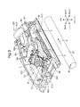
- FIG. 3 is a perspective view showing the internal structure of the exposure device 123 according to this embodiment.
- FIG. 4 is a top view of the exposure device 123.
- FIGS. 3 and 4 show a state that a housing top 80T (see FIG. 5 ) of the exposure device 123 is removed.
- the exposure device 123 includes a housing 80, a laser diode 81 (laser light source), lens elements 82, 83, a polygon motor unit 7, an f ⁇ lens 85, and a fold mirror 86.
- the housing 80 is a housing in which various elements of the exposure device 123 are contained.
- the housing 80 has an approximately rectangular shape in top view and a flat shape with a predetermined thickness in a vertical direction.
- the housing 80 includes a housing body 80G and the housing top 80T (see FIG. 5 ).
- the housing body 80G is defined on the right, rear, left, and front sides by a right wall 810, a rear wall 811, a left wall 812 (first wall portion), and a front wall 813 (second wall portion), respectively.
- the housing top 80T is fitted over the housing body 80G and directly mounted to the right wall 810, the rear wall 811, the left wall 812, and the front wall 813.
- the interior of the housing 80 is formed into an internal space S in which various optical elements are arranged.
- the laser diode 81 modulates an image data signal, which is generated by and output from an image memory located outside of the figures, into laser light and emits (outputs) the laser light.
- the laser diode 81 is disposed in the inside of the right wall 810 of the housing 80.
- the laser diode 81 is electrically connected to an unshown circuit board configured to control the timing of emission of the laser light and so on.
- the lens elements 82, 83 are formed of, for example, a collimator lens or a prism and have the function of converting the incident laser light to collimated light.
- the polygon motor unit 7 is disposed in a substantially central portion of the housing 80.
- the polygon motor unit 7 includes a polygon motor 71 mounted on a board and a polygon mirror 72.
- the polygon motor 71 is configured to input a drive current and thereby rotate the polygon mirror 72 at a predetermined rotational speed.
- the polygon mirror 72 is formed in a flat-plate shape of regular hexagon in plan view and includes a plurality of mirror surfaces.
- the polygon mirror 72 is driven into rotation in the direction of the arrow DP in FIGS. 3 and 4 .
- the polygon motor 71 rotates the polygon mirror 72 so that the plurality of mirror surfaces of the polygon mirror 72 sequentially face the left wall 812 and then face the front wall 813. While being rotated by the polygon motor 71, the polygon mirror 72 deflects the laser light coming from the lens element 83 to direct it toward the f ⁇ lens 85.
- the f ⁇ lens 85 is disposed forwardly of the polygon motor unit 7 along a right-and-left direction.
- the f ⁇ lens 85 is disposed between the polygon motor 71 and the front wall 813 to extend in a direction perpendicular to the left wall 812.
- the f ⁇ lens 85 has an approximately arched shape in top view. Particularly, the midportion of the f ⁇ lens 85 protrudes toward the polygon mirror 72 and both ends thereof protrudes toward the fold mirror 86 (and the front wall 813).
- the f ⁇ lens 85 has the function of refracting the laser light deflected by the polygon mirror 72 to allow the laser light to scan the photosensitive drum 121 at a constant speed.
- the fold mirror 86 is provided to reflect the laser light coming from the f ⁇ lens 85 and guide it to the photosensitive drum 121.
- the housing 80 further includes an extension 801.
- the extension 801 is a wall portion provided in the internal space S and extended from the inside wall surface of the left wall 812.
- the extension 801 partitions the corner between the left wall 812 and the front wall 813 into a portion near the left wall 812 and a portion near the front wall 813.
- the extension 801 is extended rightward from the inside wall surface of the left wall 812, then bent rearward, and then bent toward the polygon motor unit 7.
- a left end portion LA of the f ⁇ lens 85 is located immediately on the right of the extension 801.
- a distal end portion 802 (partition) of the extension 801 is located behind the left end portion LA of the f ⁇ lens 85 and extended toward the mirror surfaces of the polygon mirror 72.
- the distal end portion 802 of the extension 801 is disposed to face a surface end region of the f ⁇ lens 85 located near the left wall 812 and facing the polygon mirror 72.
- the laser light emitted from the laser diode 81 is guided through the lens elements 82, 83 to the polygon mirror 72.
- the laser light incident on the rotating polygon mirror 72 is reflected and deflected by the mirror surfaces of the polygon mirror 72.
- the laser light passes through the f ⁇ lens 85, is reflected by the fold mirror 86, and is then guided to the drum surface of the rotating photosensitive drum 121.
- the photosensitive drum 121 rotates about the axis orthogonal to a predetermined scanning direction (in the sub-scanning direction, or the direction of the arrow B in FIG. 3 ) while the laser light horizontally scans the drum surface of the photosensitive drum 121 in the predetermined scanning direction (the main scanning direction, or the direction of the arrow A in FIG. 3 ).
- the polygon motor 71 When the polygon motor 71 is driven into rotation, heat generated from the polygon motor 71 is diffused into the housing 80 by a laminar airflow formed with the rotation of the polygon motor 71. Then, as shown by an area H in FIG. 4 , the warmed air is distributed over an area extending from the polygon motor unit 7 to a corner formed between the left wall 812 and the f ⁇ lens 85. As a result, the left end portion LA of the f ⁇ lens 85 (a portion thereof near the left wall 812) reaches a higher temperature than a right end portion LB (a portion thereof away from the left wall 812) to cause a temperature gradient in the f ⁇ lens 85.
- the left end portion LA may be thermally expanded to a greater degree than the right end portion LB, so that the f ⁇ lens 85 may have refractive index differences in the right-and-left direction (the direction of extension) of the f ⁇ lens 85.
- the refractive index differences induce distortion of the electrostatic latent image on the photosensitive drum 121, resulting in a defective image formed by the image forming apparatus 1.
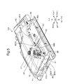
- FIG. 5 is a perspective view of the exposure device 123 according to this embodiment similar to, but different from FIG. 3 in that the exposure device 123 includes the housing top 80T.
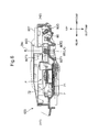
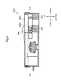
- FIGS. 6 and 7 are cross-sectional views of the exposure device 123.
- FIG. 6 is a cross-sectional view taken along the line H1-H2 of FIG. 5
- FIG. 7 is a cross-sectional view taken along the line L1-L2 of FIG. 5 .
- the exposure device 123 includes a heat-insulating room 50.
- the heat-insulating room 50 is disposed above the portion of the f ⁇ lens 85 away from the left wall 812 and insulates heat transferred from the internal space S above.
- the heat-insulating room 50 is defined by a recess 80D, a plate 500 (cover member), and a standing wall 80T5.
- the recess 80D is a recess formed in the housing top 80T above and along the f ⁇ lens 85.
- the recess 80D is disposed to cover the top of the f ⁇ lens 85 from its left end portion LA (see FIG. 4 ) to its right end portion LB.
- the plate 500 is a sheet material fitted to the top surface of the housing top 80T.
- the plate 500 covers, from above, a region of the recess 80D away from the left wall 812, i.e., the right end portion LB.
- the plate 500 is a label attached to the top surface of the housing 80 of the exposure device 123 and indicating safety standards relating to laser light of the laser diode 81.
- the plate 500 indicates, for example, the laser class of the laser diode 81.
- the standing wall 80T5 is a wall portion vertically extending in a midportion of the recess 80D in the right-and-left direction of the recess 80D.
- the standing wall 80T5 defines the left side of the heat-insulating room 50 (the side thereof near the left wall 812).
- the recess 80D is located above the f ⁇ lens 85 (its left end portion LA) which will be warmed by the air accumulated in the area H (see FIG. 4 ).
- the recess 80D is defined on the front, rear, and bottom sides by a recess front wall 80T2, a recess rear wall 80T3, and a recess bottom wall 80T1, respectively.
- the heat transferred from the high-temperature f ⁇ lens 85 through the recess bottom wall 80T1 into the recess 80D is released as an upward airflow to an upper region of the exposure device 123.
- the plate 500 does not cover a region of the recess 80D located above the left end portion LA of the f ⁇ lens 85, the heat transferred into the recess 80 is released to the upper region of the exposure device 123.
- the heat-insulating room 50 is disposed above the f ⁇ lens 85 (its right end portion LB).
- An air layer is formed inside the heat-insulating room 50.
- the heat-insulating room 50 is defined by the recess 80D and the plate 500 disposed above the recess 80D.
- the housing top 80T includes a recess inner wall 80T4 above the right end portion LB of the f ⁇ lens85.
- the recess 80D is defined by the recess inner wall 80T4, the recess bottom wall 80T1, and the recess front wall 80T2.
- the housing top 80T may have a configuration without the recess inner wall 80T4. In other words, also in FIG. 7 (the right end portion LB) like FIG.
- the recess 80D may be defined by the recess rear wall 80T3, the recess bottom wall 80T1, and the recess front wall 80T2.
- the plate 500 is extended from the top of the recess front wall 80T2 to the top of the recess rear wall 80T3.
- the right end portion LB of the f ⁇ lens 85 is slightly warmed by heat transfer from the left end portion LA and heat transferred from the internal space S. Then, the heat is transferred from the right end portion LB of the f ⁇ lens 85 to the recess bottom wall 80T1. However, the heat is insulated by the heat-insulating room 50 and is therefore less likely to be released to the upper region of the exposure device 123. Therefore, the amount of heat transferred from the f ⁇ lens 85 to the recess bottom wall 80T1 can be reduced to reduce the temperature drop of the f ⁇ lens 85 (its right end portion LB).
- the above heat insulating effect can be further ensured to provide a uniform temperature inside the housing 80.
- the recess bottom wall 80T1 is preferably disposed in contact with the top surface of the f ⁇ lens 85.
- the standing wall 80T5 defines the left side of the heat-insulating room 50.
- the standing wall 80T5 separates the region of the recess 80D located above the left end portion LA of the f ⁇ lens 85 from the region of the recess 80D located above the right end portion LB of the f ⁇ lens 85, the heat transferred to the region of the recess 80D located above the left end portion LA can be prevented from transferring toward the region (heat-insulating room 50) of the recess 80D located above the right end portion LB.
- the housing 80 includes the extension 801 provided in the internal space S and extended from the inside wall surface of the left wall 812. Furthermore, the distal end portion 802 of the extension 801 is located behind the left end portion LA of the f ⁇ lens 85 and extended toward the mirror surfaces of the polygon mirror 72. Therefore, it can be prevented that the warm air accumulated in the area H comes into contact with the left end portion LA of the f ⁇ lens 85. Thus, the temperature rise of the left end portion LA of the f ⁇ lens 85 can be reduced to further reduce the temperature gradient of the f ⁇ lens 85 in the direction of extension.
- the main body internal space 260 in which the exposure device 123 is mounted has a feature.
- the printer 100 further includes a fan 550 (see FIG. 2 ) as the airflow generating device and an air passage 555 as the cooling air passage.
- the fan 550 is disposed in the inside of an upper wall left side portion 201F (see FIG. 1 ) of the upper wall 201 located on the left of the paper output section 210.
- An unshown air intake is formed in the outside wall of the housing 200 to face the fan 550.
- the fan 550 is connected to an unshown motor and can be driven into rotation by the motor.
- the fan 550 allows airflow to enter the main body internal space 260 from the outside of the housing 200.
- the air passage 555 guides the airflow, which has been taken in by the fan 550, along the housing top 80T of the exposure device 123.
- the air passage 555 is defined by the bottom surface of the paper output section 210 and the top surface (housing top 80T) of the exposure device 123.
- the airflow taken in the main body internal space 260 by the fan 550 flows through the air passage 555 along the housing top 80T from the left wall 812 toward the right wall 810 (see the arrows A1 and A2 in FIG. 5 ). During this flow, the airflow passes by a portion of the housing top 80T located above the portion of the f ⁇ lens 85 near the left wall 812.
- the airflow promotes the heat release from the portion of the f ⁇ lens 85 near the left wall 812. Subsequently, the airflow passes above the heat-insulating room 50. Therefore, the heat taken from above the portion of the f ⁇ lens 85 near the left wall 812 can be supplied to the heat-insulating room 50. Thus, the temperature gradient of the f ⁇ lens 85 in the direction of extension can be further reduced.
- heat generated from the polygon motor 71 accumulates in the area H (see FIG. 4 ) to warm the portion of the f ⁇ lens 85 near the left wall 812.
- a temperature gradient occurs between the portion (left end portion LA) of the f ⁇ lens 85 near the left wall 812 and the portion (right end portion LB) thereof away from the left wall 812.
- the temperature gradient may induce thermal expansion differences among portions of the f ⁇ lens 85, so that the f ⁇ lens 85 may have refractive index differences in the direction of extension of the f ⁇ lens 85.
- the heat-insulating room 50 insulating heat radiated from the internal space S is disposed above the portion of the f ⁇ lens 85 away from the left wall 812. Therefore, in an area around the portion of the f ⁇ lens 85 located away from the left wall 812 and likely to have a lower temperature than the portion thereof near the left wall 812, heat release from inside to outside of the exposure device 123 can be restricted. On the other hand, in an area around the portion of the f ⁇ lens 85 located near the left wall 812 and likely to have a higher temperature, heat release from inside to outside of the exposure device 123 is not restricted because of absence of the heat-insulating room above this portion of the f ⁇ lens. Thus, the occurrence of a temperature gradient of the f ⁇ lens 85 in the direction of extension thereof can be reduced.
- the heat-insulating room 50 is defined, in a portion of the housing top 80T located above the f ⁇ lens 85, by the recess 80D formed along the f ⁇ lens 85 and the plate 500 covering the region of the recess 80D away from the left wall 812. Therefore, part of the heat-insulating room 50 is defined by a simple structure formed of the recess 80D formed in the housing top 80T and the plate 500.
- the temperature gradient of the f ⁇ lens 85 in the direction of extension can be reduced, which eliminates the need to provide an expensive thermally conductive member in the exposure device 123.
- the exposure device 123 can be reduced in cost.
- the heat-insulating room 50 is further defined by the standing wall 80T5 directly connected to the recess 80D and the plate 500 and terminating the heat-insulating room 50 at the end near the left wall 812. Therefore, the side of the heat-insulating room 50 near the left wall 812 can be closed to increase the hermeticity of the heat-insulating room 50.
- the plate 500 is a label indicating safety standards relating to laser light of the laser diode 81. Therefore, the label indicating safety standards relating to laser light of the laser diode 81 can be used also as the plate 500.
- the printer 100 of the above embodiment includes: the fan 550 allowing airflow to enter the main body internal space 260 in the housing 200; and the air passage 555 configured to guide the airflow taken in the main body internal space 260 along the housing top 80T.
- the airflow taken in the main body internal space 260 by the fan 550 is guided to a portion of the housing top 80T located above the portion of the f ⁇ lens 85 near the left wall 812.
- heat release from the portion of the f ⁇ lens 85 located near the left wall 812 and likely to have a higher temperature is promoted.
- the temperature gradient of the f ⁇ lens 85 in the direction of extension can be further reduced.
- the air passage 555 guides the airflow from the left wall 812 toward the heat-insulating room 50.
- the airflow is guided to the portion of the housing top 80T located above the portion of the f ⁇ lens 85 near the left wall 812, it is brought above the heat-insulating room 50. Therefore, the heat taken from above the portion of the f ⁇ lens 85 near the left wall 812 can be supplied to the heat-insulating room 50, so that, in an area around the portion of the f ⁇ lens 85 located away from the left wall 812 and likely to have a lower temperature than the portion thereof near the left wall 812, heat release from inside to outside of the exposure device 123 can be further restricted. As a result, the temperature gradient of the f ⁇ lens 85 in the direction of extension can be further reduced.
- the exposure device 123 according to the embodiment of the present disclosure and the printer 100 (image forming apparatus) with the same have been described thus far, the present disclosure is not limited to them and can take, for example, the following modified embodiments.
- the plate 500 may be a plate exclusively for defining the top side of the heat-insulating room 50.
- materials that can be used for the plate 500 include a porous elastic material and a resin-made sheet material. Particularly if a porous elastic material is used as the plate 500, heat accumulated in the heat-insulating room 50 can be released little by little. Therefore, it can be prevented that heat is excessively accumulated in the heat-insulating room 50.
- FIG. 8 is a perspective view of an exposure device 123A according to a modified embodiment of the present disclosure.
- FIGS. 9 is cross-sectional views of different heat-insulating rooms 50A of different exposure devices 123A.
- FIGS. 10 is cross-sectional views of different heat-insulating rooms 50B of different exposure devices 123B.
- a recess 80DA may be formed above and across both of an f ⁇ lens 85A and a fold mirror 86A.
- a plate 500A is disposed above a region of the recess 80DA corresponding to a portion of the f ⁇ lens 85A located away from a left wall 812A and likely to have a lower temperature than a portion thereof near the left wall 812A.
- the heat release from the portion of the f ⁇ lens 85A away from the left wall 812A can be appropriately reduced to reduce the temperature gradient of the f ⁇ lens 85A in the direction of extension.
- the interior of the heat-insulating room 50B may be separated into a plurality of subrooms 80DB. Also in this case, the individually separated heat-insulating subrooms restrict upward heat release from an f ⁇ lens 85B and a fold mirror 86B.
Landscapes
- Physics & Mathematics (AREA)
- General Physics & Mathematics (AREA)
- Optics & Photonics (AREA)
- Engineering & Computer Science (AREA)
- Environmental & Geological Engineering (AREA)
- Multimedia (AREA)
- Signal Processing (AREA)
- Laser Beam Printer (AREA)
- Mechanical Optical Scanning Systems (AREA)
- Facsimile Scanning Arrangements (AREA)
- Exposure Or Original Feeding In Electrophotography (AREA)
Abstract
Description
- The present disclosure relates to an optical scanning device configured to form an electrostatic latent image on an image carrier and an image forming apparatus with the optical scanning device.
- An image forming apparatus includes an optical scanning device configured to form an electrostatic latent image on a photosensitive drum capable of carrying an image. An exposure device serving as the optical scanning device may include a laser diode, a lens, a polygon mirror, a polygon motor, an fθ lens, and a fold mirror all of which are contained in a housing.
- Laser light emitted from the laser diode is guided through the lens to the polygon mirror. Then, the laser light incident on the polygon mirror driven into rotation by the motor is reflected and deflected by the mirror surfaces of the polygon mirror, then passes through the fθ lens, and is then reflected by the fold mirror. Thus, the laser light is guided to the drum surface of the photosensitive drum rotating in a sub-scanning direction and scans the drum surface in a main scanning direction.
- With the rotation of the polygon mirror, heat generated from the polygon motor may be unevenly distributed in the housing to cause a temperature gradient in the fθ lens and thus cause unevenness in refractive index of the fθ lens. To cope with this, a thermally conductive member may be disposed between a high-temperature portion and a low-temperature portion inside the housing to make the internal temperature of the housing uniform.
- Alternatively, a metallic member may be disposed between a main frame of the image forming apparatus to which the exposure device is mounted and the housing of the exposure device. The metallic member is directly mounted to the main frame and changed in shape between the high-temperature portion and the low-temperature portion in the housing to give a difference in heat dissipation performance and thereby make the internal temperature of the housing uniform.
- A technique further modified from the above known techniques is proposed as an aspect of the present disclosure.
- Specifically, an optical scanning device according to an aspect of the present disclosure includes a housing, a laser light source, a polygon mirror, a polygon motor, an fθ lens, and a heat-insulating room.
- The housing includes a first wall portion, a second wall portion intersecting with the first wall portion, and a housing top directly mounted on top of the first and second wall portions.
- The laser light source is configured to emit laser light.
- The polygon mirror includes a plurality of mirror surfaces and is disposed in an internal space defined by the housing. The polygon mirror is configured to be driven into rotation and deflect the laser light.
- The polygon motor is configured to rotate the polygon mirror so that the plurality of mirror surfaces sequentially face the first wall portion and then face the second wall portion.
- The fθ lens is disposed between the polygon motor and the second wall portion to extend in a direction perpendicular to the first wall portion and is configured to refract the laser light deflected by the polygon mirror.
- The heat-insulating room is disposed in an area above a portion of the fθ lens away from the first wall portion in a direction of extension of the fθ lens and insulates heat radiated from the internal space.
- An image forming apparatus according to another aspect of the present disclosure includes an image carrier, a charging section, an exposure section, and a developing section.
- A toner image is formed on a surface of the image carrier.
- The charging section is configured to charge the surface of the image carrier.
- The exposure section is configured to expose the surface of the image carrier charged by the charging section to light to form an electrostatic latent image on the surface of the image carrier.
- The developing section is configured to supply toner to the electrostatic latent image formed by the exposure section to form the toner image.
- The exposure section includes:
- a housing including a first wall portion, a second wall portion intersecting with the first wall portion, and a housing top directly mounted on top of the first and second wall portions;
- a laser light source configured to emit laser light;
- a polygon mirror disposed in an internal space defined by the housing, configured to be driven into rotation and deflect the laser light, and including a plurality of mirror surfaces;
- a polygon motor being configured to rotate the polygon mirror so that the mirror surfaces sequentially face the first wall portion and then face the second wall portion;
- an fθ lens disposed between the polygon motor and the second wall portion to extend in a direction perpendicular to the first wall portion and configured to refract the laser light deflected by the polygon mirror; and
- a heat-insulating room disposed in an area above a portion of the fθ lens away from the first wall portion in a direction of extension of the fθ lens and insulating heat radiated from the internal space.
-
-
FIG. 1 is a perspective view of an image forming apparatus according to an embodiment of the present disclosure. -
FIG. 2 is an internal cross-sectional view of the image forming apparatus according to the embodiment of the present disclosure. -
FIG. 3 is an exploded perspective view of an exposure device according to the embodiment of the present disclosure. -
FIG. 4 is a top view of the exposure device according to the embodiment of the present disclosure. -
FIG. 5 is a perspective view of the exposure device according to the embodiment of the present disclosure. -
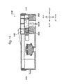
FIG. 6 is a cross-sectional view of the exposure device according to the embodiment of the present disclosure. -
FIG. 7 is another cross-sectional view of the exposure device according to the embodiment of the present disclosure. -
FIG. 8 is a perspective view of an exposure device according to another embodiment of the present disclosure. -
FIG. 9 is a cross-sectional view of the exposure device according to the embodiment ofFIG. 8 . -
FIG. 10 is a cross-sectional view of an exposure device according to still another embodiment of the present disclosure. - Hereinafter, a description will be given of an embodiment of the present disclosure with reference to the drawings.
FIG. 1 is a perspective view of a printer 100 (image forming apparatus) according to an embodiment of the present disclosure.FIG. 2 is a view schematically showing an internal structure of theprinter 100 shown inFIG. 1 . Theprinter 100 shown inFIGS. 1 and2 is a so-called black-and-white printer. However, in other embodiments, the image forming apparatus may be a color printer, a facsimile machine, a multifunction peripheral having these functions, or another apparatus for forming a toner image on a sheet. Note that directional terms, such as "top", "bottom", "above", "below", "front", "rear", "right", and "left", used herein are simply for ease of explanation and not at all intended to limit the principle of the image forming apparatus. - The
printer 100 includes ahousing 200 in which various devices for forming an image on a sheet P are contained. Thehousing 200 includes anupper wall 201 defining a top surface of thehousing 200, abottom wall 220 defining a bottom surface of thehousing 200, a back wall 230 (seeFIG. 2 ) standing between theupper wall 201 and thebottom wall 220, and afront wall 235 standing opposite to theback wall 230. Apaper output section 210 is disposed in the center of theupper wall 201. Thepaper output section 210 is formed of an inclined surface inclined downward from a front portion to a rear portion of theupper wall 210. Thepaper output section 210 is a section to which a sheet P having an image formed thereon in animage forming section 120 to be described later is to be output. Amanual feed tray 240 is disposed in thefront wall 235. Themanual feed tray 240 is pivotable up and down (in the direction of the arrow D1 inFIG. 2 ) about its lower end. When the upper end of the manual-feed tray 240 is pivotally moved downward, an opening 290 formed in thehousing 200 is open. The opening 290 is communicated with a main body internal space 260 (installation space) inside thehousing 200. The user can access, through the opening 290, various devices housed in the main bodyinternal space 260 in thehousing 200. When the manual-feed tray 240 is pivotally moved upward, the opening 290 is closed. Thus, unnecessary access of the user to the main bodyinternal space 260 is prevented. - The
printer 100 includes acassette 110, a pick-up roller 112, a firstpaper feed roller 113, a secondpaper feed roller 114, aconveyance roller 115, aregistration roller pair 116, and animage forming section 120. - The
cassette 110 is configured to contain a plurality of sheets P. Thecassette 110 includes alift plate 111 capable of supporting the sheets P. Thelift plate 111 is inclined to lift up the leading edges of the sheets P. - The pick-up
roller 112 is disposed above the leading edges of the sheets P lifted up by thelift plate 111. When the pick-uproller 112 rotates, the sheets P are pulled out of thecassette 110 one by one. - The first
paper feed roller 113 is disposed downstream of the pick-uproller 112. The firstpaper feed roller 113 forwards the sheet P downstream. The secondpaper feed roller 114 is disposed near the pivot point of themanual feed tray 240. The secondpaper feed roller 114 feeds the sheet P on themanual feed tray 240 into thehousing 200. The user can selectively use the sheet P contained in thecassette 110 or the sheet P placed on the manual-feed tray 240. - The
conveyance roller 115 is disposed downstream of the firstpaper feed roller 113 and the secondpaper feed roller 114. Theconveyance roller 115 conveys the sheet P forwarded by the firstpaper feed roller 113 and the secondpaper feed roller 114 more downstream. - The
registration roller pair 116 defines the position of the sheet in a direction orthogonal to a direction of conveyance. Thus, the position of an image to be formed on the sheet P is adjusted. Theregistration roller pair 116 supplies the sheet P to theimage forming section 120 to coincide with the timing of image formation of theimage forming section 120. - The
image forming section 120 includes aphotosensitive drum 121, acharger 122, an exposure device 123 (optical scanning device), a developingdevice 124, atoner container 125, atransfer roller 126, and acleaning device 127. - The
photosensitive drum 121 has an approximately cylindrical shape. Thephotosensitive drum 121 is configured to form an electrostatic latent image on its peripheral surface and carry a toner image corresponding to the electrostatic latent image. - The
charger 122 is configured to be given a predetermined voltage and substantially uniformly charge the peripheral surface of thephotosensitive drum 121. Theexposure device 123 is configured to irradiate the peripheral surface of thephotosensitive drum 121 charged by thecharger 122 with laser light. The laser light is emitted according to image data output from an external device (not shown), such as a personal computer, which is connected to theprinter 100 to allow communication with theprinter 100. As a result, an electrostatic latent image corresponding to the image data is formed on the peripheral surface of thephotosensitive drum 121. Theexposure device 123 will be described in detail later. - The developing
device 124 is configured to supply toner to the peripheral surface of thephotosensitive drum 121 on which the electrostatic latent image is formed. Thetoner container 125 is configured to supply toner to the developingdevice 124. Thetoner container 125 supplies toner to the developingdevice 124 sequentially or as needed. When the developingdevice 124 supplies toner to thephotosensitive drum 121, the electrostatic latent image formed on the peripheral surface of thephotosensitive drum 121 is developed (made visible). As a result, a toner image is formed on the peripheral surface of thephotosensitive drum 121. - The
transfer roller 126 is rotatably disposed in contact with the peripheral surface of thephotosensitive drum 121. While the sheet P conveyed from theregistration roller pair 116 passes between thephotosensitive drum 121 and thetransfer roller 126, the toner image formed on the peripheral surface of thephotosensitive drum 121 is transferred to the sheet P. - The
cleaning device 127 removes residual toner on the peripheral surface of thephotosensitive drum 121 after the toner image is transferred to the sheet P. The peripheral surface of thephotosensitive drum 121 cleaned up by thecleaning device 127 passes below thecharger 122 again and is thereby uniformly charged. Thereafter, the above formation of a toner image is performed for the next sheet P. - The
printer 100 further includes afixing device 130 disposed downstream of theimage forming section 120 in the direction of conveyance and configured to fix the toner image on the sheet P. The fixingdevice 130 includes: aheat roller 131 configured to melt the toner on the sheet P; and apressure roller 132 configured to bring the sheet P into close contact with theheat roller 131. When the sheet P passes between theheat roller 131 and thepressure roller 132, the toner images is fixed on the sheet P. - The
printer 100 further includes: a plurality of conveyance roller pairs 133 disposed downstream of the fixingdevice 130; and anoutput roller pair 134 disposed downstream of the conveyance roller pairs 133. The sheet P is conveyed upward by the conveyance roller pairs 133 and finally output from thehousing 200 by theoutput roller pair 134. The sheets P output from thehousing 200 are piled up on thepaper output section 210. - Next, a description will be given of the structure of the
exposure device 123 according to this embodiment with reference toFIGS. 3 and4 .FIG. 3 is a perspective view showing the internal structure of theexposure device 123 according to this embodiment.FIG. 4 is a top view of theexposure device 123.FIGS. 3 and4 show a state that ahousing top 80T (seeFIG. 5 ) of theexposure device 123 is removed. Theexposure device 123 includes ahousing 80, a laser diode 81 (laser light source),lens elements polygon motor unit 7, anfθ lens 85, and afold mirror 86. - The
housing 80 is a housing in which various elements of theexposure device 123 are contained. Thehousing 80 has an approximately rectangular shape in top view and a flat shape with a predetermined thickness in a vertical direction. Thehousing 80 includes ahousing body 80G and thehousing top 80T (seeFIG. 5 ). Thehousing body 80G is defined on the right, rear, left, and front sides by aright wall 810, arear wall 811, a left wall 812 (first wall portion), and a front wall 813 (second wall portion), respectively. Thehousing top 80T is fitted over thehousing body 80G and directly mounted to theright wall 810, therear wall 811, theleft wall 812, and thefront wall 813. The interior of thehousing 80 is formed into an internal space S in which various optical elements are arranged. - The
laser diode 81 modulates an image data signal, which is generated by and output from an image memory located outside of the figures, into laser light and emits (outputs) the laser light. Thelaser diode 81 is disposed in the inside of theright wall 810 of thehousing 80. Thelaser diode 81 is electrically connected to an unshown circuit board configured to control the timing of emission of the laser light and so on. Thelens elements - The
polygon motor unit 7 is disposed in a substantially central portion of thehousing 80. Thepolygon motor unit 7 includes apolygon motor 71 mounted on a board and apolygon mirror 72. Thepolygon motor 71 is configured to input a drive current and thereby rotate thepolygon mirror 72 at a predetermined rotational speed. Thepolygon mirror 72 is formed in a flat-plate shape of regular hexagon in plan view and includes a plurality of mirror surfaces. Thepolygon mirror 72 is driven into rotation in the direction of the arrow DP inFIGS. 3 and4 . In other words, thepolygon motor 71 rotates thepolygon mirror 72 so that the plurality of mirror surfaces of thepolygon mirror 72 sequentially face theleft wall 812 and then face thefront wall 813. While being rotated by thepolygon motor 71, thepolygon mirror 72 deflects the laser light coming from thelens element 83 to direct it toward thefθ lens 85. - The
fθ lens 85 is disposed forwardly of thepolygon motor unit 7 along a right-and-left direction. Thefθ lens 85 is disposed between thepolygon motor 71 and thefront wall 813 to extend in a direction perpendicular to theleft wall 812. Thefθ lens 85 has an approximately arched shape in top view. Particularly, the midportion of thefθ lens 85 protrudes toward thepolygon mirror 72 and both ends thereof protrudes toward the fold mirror 86 (and the front wall 813). Thefθ lens 85 has the function of refracting the laser light deflected by thepolygon mirror 72 to allow the laser light to scan thephotosensitive drum 121 at a constant speed. Thefold mirror 86 is provided to reflect the laser light coming from thefθ lens 85 and guide it to thephotosensitive drum 121. - The
housing 80 further includes anextension 801. Theextension 801 is a wall portion provided in the internal space S and extended from the inside wall surface of theleft wall 812. Theextension 801 partitions the corner between theleft wall 812 and thefront wall 813 into a portion near theleft wall 812 and a portion near thefront wall 813. Theextension 801 is extended rightward from the inside wall surface of theleft wall 812, then bent rearward, and then bent toward thepolygon motor unit 7. A left end portion LA of thefθ lens 85 is located immediately on the right of theextension 801. Furthermore, a distal end portion 802 (partition) of theextension 801 is located behind the left end portion LA of thefθ lens 85 and extended toward the mirror surfaces of thepolygon mirror 72. In other words, thedistal end portion 802 of theextension 801 is disposed to face a surface end region of thefθ lens 85 located near theleft wall 812 and facing thepolygon mirror 72. - In this
exposure device 123, the laser light emitted from thelaser diode 81 is guided through thelens elements polygon mirror 72. The laser light incident on therotating polygon mirror 72 is reflected and deflected by the mirror surfaces of thepolygon mirror 72. Then, the laser light passes through thefθ lens 85, is reflected by thefold mirror 86, and is then guided to the drum surface of the rotatingphotosensitive drum 121. During this time, thephotosensitive drum 121 rotates about the axis orthogonal to a predetermined scanning direction (in the sub-scanning direction, or the direction of the arrow B inFIG. 3 ) while the laser light horizontally scans the drum surface of thephotosensitive drum 121 in the predetermined scanning direction (the main scanning direction, or the direction of the arrow A inFIG. 3 ). - When the
polygon motor 71 is driven into rotation, heat generated from thepolygon motor 71 is diffused into thehousing 80 by a laminar airflow formed with the rotation of thepolygon motor 71. Then, as shown by an area H inFIG. 4 , the warmed air is distributed over an area extending from thepolygon motor unit 7 to a corner formed between theleft wall 812 and thefθ lens 85. As a result, the left end portion LA of the fθ lens 85 (a portion thereof near the left wall 812) reaches a higher temperature than a right end portion LB (a portion thereof away from the left wall 812) to cause a temperature gradient in thefθ lens 85. Thus, the left end portion LA may be thermally expanded to a greater degree than the right end portion LB, so that thefθ lens 85 may have refractive index differences in the right-and-left direction (the direction of extension) of thefθ lens 85. The refractive index differences induce distortion of the electrostatic latent image on thephotosensitive drum 121, resulting in a defective image formed by the image forming apparatus 1. - Even in the above case of heat diffusion, in this embodiment, the temperature gradient of the
fθ lens 85 in the right-and-left direction can be appropriately reduced.FIG. 5 is a perspective view of theexposure device 123 according to this embodiment similar to, but different fromFIG. 3 in that theexposure device 123 includes thehousing top 80T.FIGS. 6 and7 are cross-sectional views of theexposure device 123.FIG. 6 is a cross-sectional view taken along the line H1-H2 ofFIG. 5 andFIG. 7 is a cross-sectional view taken along the line L1-L2 ofFIG. 5 . - The
exposure device 123 includes a heat-insulatingroom 50. The heat-insulatingroom 50 is disposed above the portion of thefθ lens 85 away from theleft wall 812 and insulates heat transferred from the internal space S above. The heat-insulatingroom 50 is defined by arecess 80D, a plate 500 (cover member), and a standing wall 80T5. - The
recess 80D is a recess formed in thehousing top 80T above and along thefθ lens 85. Therecess 80D is disposed to cover the top of thefθ lens 85 from its left end portion LA (seeFIG. 4 ) to its right end portion LB. - The
plate 500 is a sheet material fitted to the top surface of thehousing top 80T. Theplate 500 covers, from above, a region of therecess 80D away from theleft wall 812, i.e., the right end portion LB. In this embodiment, theplate 500 is a label attached to the top surface of thehousing 80 of theexposure device 123 and indicating safety standards relating to laser light of thelaser diode 81. Theplate 500 indicates, for example, the laser class of thelaser diode 81. - The standing wall 80T5 is a wall portion vertically extending in a midportion of the
recess 80D in the right-and-left direction of therecess 80D. The standing wall 80T5 defines the left side of the heat-insulating room 50 (the side thereof near the left wall 812). - Referring to
FIG. 6 , therecess 80D is located above the fθ lens 85 (its left end portion LA) which will be warmed by the air accumulated in the area H (seeFIG. 4 ). Therecess 80D is defined on the front, rear, and bottom sides by a recess front wall 80T2, a recess rear wall 80T3, and a recess bottom wall 80T1, respectively. The heat transferred from the high-temperature fθ lens 85 through the recess bottom wall 80T1 into therecess 80D is released as an upward airflow to an upper region of theexposure device 123. Specifically, since theplate 500 does not cover a region of therecess 80D located above the left end portion LA of thefθ lens 85, the heat transferred into therecess 80 is released to the upper region of theexposure device 123. - On the other hand, referring to
FIG. 7 , the heat-insulatingroom 50 is disposed above the fθ lens 85 (its right end portion LB). An air layer is formed inside the heat-insulatingroom 50. The heat-insulatingroom 50 is defined by therecess 80D and theplate 500 disposed above therecess 80D. Thehousing top 80T includes a recess inner wall 80T4 above the right end portion LB of the fθ lens85. Thus, therecess 80D is defined by the recess inner wall 80T4, the recess bottom wall 80T1, and the recess front wall 80T2. Thehousing top 80T may have a configuration without the recess inner wall 80T4. In other words, also inFIG. 7 (the right end portion LB) likeFIG. 6 , therecess 80D may be defined by the recess rear wall 80T3, the recess bottom wall 80T1, and the recess front wall 80T2. In this case, theplate 500 is extended from the top of the recess front wall 80T2 to the top of the recess rear wall 80T3. - The right end portion LB of the
fθ lens 85 is slightly warmed by heat transfer from the left end portion LA and heat transferred from the internal space S. Then, the heat is transferred from the right end portion LB of thefθ lens 85 to the recess bottom wall 80T1. However, the heat is insulated by the heat-insulatingroom 50 and is therefore less likely to be released to the upper region of theexposure device 123. Therefore, the amount of heat transferred from thefθ lens 85 to the recess bottom wall 80T1 can be reduced to reduce the temperature drop of the fθ lens 85 (its right end portion LB). When the heat-insulatingroom 50 is disposed in contact with the top surface of thefθ lens 85, the above heat insulating effect can be further ensured to provide a uniform temperature inside thehousing 80. For example, the recess bottom wall 80T1 is preferably disposed in contact with the top surface of thefθ lens 85. Furthermore, in this embodiment, the standing wall 80T5 defines the left side of the heat-insulatingroom 50. Thus, the hermeticity of the interior of the heat-insulatingroom 50 is increased to enhance the heat insulating effect of the heat-insulatingroom 50. In other words, since the standing wall 80T5 separates the region of therecess 80D located above the left end portion LA of thefθ lens 85 from the region of therecess 80D located above the right end portion LB of thefθ lens 85, the heat transferred to the region of therecess 80D located above the left end portion LA can be prevented from transferring toward the region (heat-insulating room 50) of therecess 80D located above the right end portion LB. - As described previously, the
housing 80 includes theextension 801 provided in the internal space S and extended from the inside wall surface of theleft wall 812. Furthermore, thedistal end portion 802 of theextension 801 is located behind the left end portion LA of thefθ lens 85 and extended toward the mirror surfaces of thepolygon mirror 72. Therefore, it can be prevented that the warm air accumulated in the area H comes into contact with the left end portion LA of thefθ lens 85. Thus, the temperature rise of the left end portion LA of thefθ lens 85 can be reduced to further reduce the temperature gradient of thefθ lens 85 in the direction of extension. - Furthermore, in this embodiment, the main body
internal space 260 in which theexposure device 123 is mounted has a feature. Specifically, referring toFIGS. 1 and2 , theprinter 100 further includes a fan 550 (seeFIG. 2 ) as the airflow generating device and anair passage 555 as the cooling air passage. - The
fan 550 is disposed in the inside of an upper wall leftside portion 201F (seeFIG. 1 ) of theupper wall 201 located on the left of thepaper output section 210. An unshown air intake is formed in the outside wall of thehousing 200 to face thefan 550. Thefan 550 is connected to an unshown motor and can be driven into rotation by the motor. Thefan 550 allows airflow to enter the main bodyinternal space 260 from the outside of thehousing 200. - The
air passage 555 guides the airflow, which has been taken in by thefan 550, along thehousing top 80T of theexposure device 123. Theair passage 555 is defined by the bottom surface of thepaper output section 210 and the top surface (housing top 80T) of theexposure device 123. The airflow taken in the main bodyinternal space 260 by thefan 550 flows through theair passage 555 along thehousing top 80T from theleft wall 812 toward the right wall 810 (see the arrows A1 and A2 inFIG. 5 ). During this flow, the airflow passes by a portion of thehousing top 80T located above the portion of thefθ lens 85 near theleft wall 812. As a result, the airflow promotes the heat release from the portion of thefθ lens 85 near theleft wall 812. Subsequently, the airflow passes above the heat-insulatingroom 50. Therefore, the heat taken from above the portion of thefθ lens 85 near theleft wall 812 can be supplied to the heat-insulatingroom 50. Thus, the temperature gradient of thefθ lens 85 in the direction of extension can be further reduced. - As described thus far, in this embodiment, heat generated from the
polygon motor 71 accumulates in the area H (seeFIG. 4 ) to warm the portion of thefθ lens 85 near theleft wall 812. As a result, a temperature gradient occurs between the portion (left end portion LA) of thefθ lens 85 near theleft wall 812 and the portion (right end portion LB) thereof away from theleft wall 812. The temperature gradient may induce thermal expansion differences among portions of thefθ lens 85, so that thefθ lens 85 may have refractive index differences in the direction of extension of thefθ lens 85. To cope with this, in the structure of this embodiment, the heat-insulatingroom 50 insulating heat radiated from the internal space S is disposed above the portion of thefθ lens 85 away from theleft wall 812. Therefore, in an area around the portion of thefθ lens 85 located away from theleft wall 812 and likely to have a lower temperature than the portion thereof near theleft wall 812, heat release from inside to outside of theexposure device 123 can be restricted. On the other hand, in an area around the portion of thefθ lens 85 located near theleft wall 812 and likely to have a higher temperature, heat release from inside to outside of theexposure device 123 is not restricted because of absence of the heat-insulating room above this portion of the fθ lens. Thus, the occurrence of a temperature gradient of thefθ lens 85 in the direction of extension thereof can be reduced. - Furthermore, in the above embodiment, the heat-insulating
room 50 is defined, in a portion of thehousing top 80T located above thefθ lens 85, by therecess 80D formed along thefθ lens 85 and theplate 500 covering the region of therecess 80D away from theleft wall 812. Therefore, part of the heat-insulatingroom 50 is defined by a simple structure formed of therecess 80D formed in thehousing top 80T and theplate 500. Thus, the temperature gradient of thefθ lens 85 in the direction of extension can be reduced, which eliminates the need to provide an expensive thermally conductive member in theexposure device 123. Hence, as compared to the case where the thermally conductive member is provided, theexposure device 123 can be reduced in cost. - Moreover, in the above embodiment, the heat-insulating
room 50 is further defined by the standing wall 80T5 directly connected to therecess 80D and theplate 500 and terminating the heat-insulatingroom 50 at the end near theleft wall 812. Therefore, the side of the heat-insulatingroom 50 near theleft wall 812 can be closed to increase the hermeticity of the heat-insulatingroom 50. - Furthermore, in the above embodiment, the
plate 500 is a label indicating safety standards relating to laser light of thelaser diode 81. Therefore, the label indicating safety standards relating to laser light of thelaser diode 81 can be used also as theplate 500. - Moreover, the
printer 100 of the above embodiment includes: thefan 550 allowing airflow to enter the main bodyinternal space 260 in thehousing 200; and theair passage 555 configured to guide the airflow taken in the main bodyinternal space 260 along thehousing top 80T. Thus, the airflow taken in the main bodyinternal space 260 by thefan 550 is guided to a portion of thehousing top 80T located above the portion of thefθ lens 85 near theleft wall 812. As a result, heat release from the portion of thefθ lens 85 located near theleft wall 812 and likely to have a higher temperature is promoted. Hence, the temperature gradient of thefθ lens 85 in the direction of extension can be further reduced. - Furthermore, in the above embodiment, the
air passage 555 guides the airflow from theleft wall 812 toward the heat-insulatingroom 50. Thus, after the airflow is guided to the portion of thehousing top 80T located above the portion of thefθ lens 85 near theleft wall 812, it is brought above the heat-insulatingroom 50. Therefore, the heat taken from above the portion of thefθ lens 85 near theleft wall 812 can be supplied to the heat-insulatingroom 50, so that, in an area around the portion of thefθ lens 85 located away from theleft wall 812 and likely to have a lower temperature than the portion thereof near theleft wall 812, heat release from inside to outside of theexposure device 123 can be further restricted. As a result, the temperature gradient of thefθ lens 85 in the direction of extension can be further reduced. - Although the
exposure device 123 according to the embodiment of the present disclosure and the printer 100 (image forming apparatus) with the same have been described thus far, the present disclosure is not limited to them and can take, for example, the following modified embodiments. - (1) Although the above embodiment has described an aspect in which the
plate 500 is a label indicating safety standards relating to laser light of thelaser diode 81, the present disclosure is not limited to this. Theplate 500 may be a plate exclusively for defining the top side of the heat-insulatingroom 50. In this case, materials that can be used for theplate 500 include a porous elastic material and a resin-made sheet material. Particularly if a porous elastic material is used as theplate 500, heat accumulated in the heat-insulatingroom 50 can be released little by little. Therefore, it can be prevented that heat is excessively accumulated in the heat-insulatingroom 50. - (2) Although the above embodiment has described an aspect in which the
recess 80D is formed in thehousing top 80T above and along thefθ lens 85, the present disclosure is not limited to this.FIG. 8 is a perspective view of anexposure device 123A according to a modified embodiment of the present disclosure.FIGS. 9 is cross-sectional views of different heat-insulatingrooms 50A ofdifferent exposure devices 123A.FIGS. 10 is cross-sectional views of different heat-insulatingrooms 50B ofdifferent exposure devices 123B. As shown inFIGS. 8 and9 , a recess 80DA may be formed above and across both of anfθ lens 85A and afold mirror 86A. Also in this case, aplate 500A is disposed above a region of the recess 80DA corresponding to a portion of thefθ lens 85A located away from aleft wall 812A and likely to have a lower temperature than a portion thereof near theleft wall 812A. Thus, the heat release from the portion of thefθ lens 85A away from theleft wall 812A can be appropriately reduced to reduce the temperature gradient of thefθ lens 85A in the direction of extension. Alternatively, as shown inFIG. 10 , the interior of the heat-insulatingroom 50B may be separated into a plurality of subrooms 80DB. Also in this case, the individually separated heat-insulating subrooms restrict upward heat release from anfθ lens 85B and afold mirror 86B. - Various modifications and alterations of this disclosure will be apparent to those skilled in the art without departing from the scope and spirit of this disclosure, and it should be understood that this disclosure is not limited to the illustrative embodiments set forth herein.
Claims (13)
- An optical scanning device including:a housing including a first wall portion, a second wall portion intersecting with the first wall portion, and a housing top directly mounted on top of the first and second wall portions;a laser light source configured to emit laser light;a polygon mirror disposed in an internal space defined by the housing, configured to be driven into rotation and deflect the laser light, and including a plurality of mirror surfaces;a polygon motor being configured to rotate the polygon mirror so that the mirror surfaces sequentially face the first wall portion and then face the second wall portion;an fθ lens disposed between the polygon motor and the second wall portion to extend in a direction perpendicular to the first wall portion and configured to refract the laser light deflected by the polygon mirror; anda heat-insulating room disposed in an area above a portion of the fθ lens away from the first wall portion in a direction of extension of the fθ lens and insulating heat radiated from the internal space.
- The optical scanning device according to claim 1, wherein a recess is formed in the housing top above and along the fθ lens and the heat-insulating room is formed by covering a region of the recess away from the first wall portion from above with a cover member.
- The optical scanning device according to claim 2, wherein a portion of the heat-insulating room corresponding to a bottom of the recess is in contact with a top surface of the fθ lens.
- The optical scanning device according to claim 2 or 3, wherein the heat-insulating room includes a standing wall extended in the recess, directly connected to the cover member, and terminating the heat-insulating room at an end thereof near the first wall portion.
- The optical scanning device according to any one of claims 2 through 4, wherein the cover member is a label indicating safety standards relating to laser light of the laser light source.
- The optical scanning device according to any one of claims 2 through 4, wherein the cover member is a porous elastic material.
- The optical scanning device according to any one of claims 2 through 4, wherein the cover member is a resin-made sheet material.
- The optical scanning device according to any one of claims 1 through 3, further including a partition disposed to face a surface end region of the fθ lens located near the first wall portion and facing the polygon mirror.
- The optical scanning device according to any one of claims 1 through 8, further including
a fold mirror configured to reflect the laser light having passed through the fθ lens and guide the laser light to a photosensitive drum,
wherein the heat-insulating room is formed above and across both of the fθ lens and the fold mirror. - The optical scanning device according to claim 9, wherein the heat-insulating room is internally provided with a partition wall extending in a direction of length of the heat-insulating room, the partition wall dividing the heat-insulating room into a plurality of subrooms arranged in a direction from a position of the fθ lens toward a position of the fold mirror.
- An image forming apparatus including:an image carrier on a surface of which a toner image is to be formed;a charging section configured to charge the surface of the image carrier;the optical scanning device according to any one of claims 1 through 10; anda developing section configured to supply toner to the electrostatic latent image formed by the optical scanning device to form the toner image.
- The image forming apparatus according to claim 11, further including:a housing having an installation space in which the optical scanning device is disposed;an airflow generating device disposed in the housing and configured to allow airflow to enter the installation space; anda cooling air passage configured to guide the airflow having entered the installation space to a portion of the housing top located above a portion of the fθ lens near the first wall portion.
- The image forming apparatus according to claim 12, wherein the cooling air passage guides the airflow from the first wall portion toward the heat-insulating room.
Applications Claiming Priority (1)
| Application Number | Priority Date | Filing Date | Title |
|---|---|---|---|
| JP2012144947A JP2014010195A (en) | 2012-06-28 | 2012-06-28 | Optical scanner and image forming apparatus including the same |
Publications (2)
| Publication Number | Publication Date |
|---|---|
| EP2680056A1 true EP2680056A1 (en) | 2014-01-01 |
| EP2680056B1 EP2680056B1 (en) | 2014-12-31 |
Family
ID=48771282
Family Applications (1)
| Application Number | Title | Priority Date | Filing Date |
|---|---|---|---|
| EP20130173836 Active EP2680056B1 (en) | 2012-06-28 | 2013-06-26 | Optical scanning device and image forming apparatus with the same |
Country Status (4)
| Country | Link |
|---|---|
| US (1) | US8842149B2 (en) |
| EP (1) | EP2680056B1 (en) |
| JP (1) | JP2014010195A (en) |
| CN (1) | CN103513419B (en) |
Cited By (1)
| Publication number | Priority date | Publication date | Assignee | Title |
|---|---|---|---|---|
| US11385457B2 (en) * | 2019-09-13 | 2022-07-12 | Canon Kabushiki Kaisha | Optical scanning device having rotating polygon mirror, and image forming apparatus including the same |
Families Citing this family (1)
| Publication number | Priority date | Publication date | Assignee | Title |
|---|---|---|---|---|
| KR101826739B1 (en) * | 2016-11-21 | 2018-02-08 | 주식회사 신도리코 | 3D printer using linear laser source |
Citations (4)
| Publication number | Priority date | Publication date | Assignee | Title |
|---|---|---|---|---|
| US20020089582A1 (en) * | 2001-01-11 | 2002-07-11 | Hisao Chikano | Image forming apparatus having ventilating device |
| US20030226958A1 (en) * | 2002-06-07 | 2003-12-11 | Mitsuhiro Ohno | Optical scanner |
| EP1481810A1 (en) * | 2003-05-30 | 2004-12-01 | Ricoh Company, Ltd. | A method and apparatus for image forming capable of preventing image quality deterioration induced by heat from an optical deflector |
| US20080069585A1 (en) * | 2006-09-15 | 2008-03-20 | Taku Amada | Optical scanning device and image forming apparatus |
Family Cites Families (7)
| Publication number | Priority date | Publication date | Assignee | Title |
|---|---|---|---|---|
| JPH1144856A (en) * | 1997-07-24 | 1999-02-16 | Canon Inc | Scanning optical device |
| JPH11183835A (en) * | 1997-12-24 | 1999-07-09 | Canon Inc | Image forming device |
| JP4617731B2 (en) | 2004-06-16 | 2011-01-26 | 富士ゼロックス株式会社 | Image forming apparatus |
| JP2006053224A (en) * | 2004-08-10 | 2006-02-23 | Ricoh Co Ltd | Optical writing apparatus and image forming apparatus |
| JP4928158B2 (en) * | 2006-05-26 | 2012-05-09 | キヤノン株式会社 | Scanning exposure apparatus and image forming apparatus |
| JP4922790B2 (en) * | 2007-03-06 | 2012-04-25 | 株式会社リコー | Optical scanning apparatus and image forming apparatus |
| JP2009128556A (en) | 2007-11-22 | 2009-06-11 | Kyocera Mita Corp | Optical scanner |
-
2012
- 2012-06-28 JP JP2012144947A patent/JP2014010195A/en active Pending
-
2013
- 2013-06-26 EP EP20130173836 patent/EP2680056B1/en active Active
- 2013-06-26 US US13/928,180 patent/US8842149B2/en active Active
- 2013-06-27 CN CN201310263653.4A patent/CN103513419B/en active Active
Patent Citations (4)
| Publication number | Priority date | Publication date | Assignee | Title |
|---|---|---|---|---|
| US20020089582A1 (en) * | 2001-01-11 | 2002-07-11 | Hisao Chikano | Image forming apparatus having ventilating device |
| US20030226958A1 (en) * | 2002-06-07 | 2003-12-11 | Mitsuhiro Ohno | Optical scanner |
| EP1481810A1 (en) * | 2003-05-30 | 2004-12-01 | Ricoh Company, Ltd. | A method and apparatus for image forming capable of preventing image quality deterioration induced by heat from an optical deflector |
| US20080069585A1 (en) * | 2006-09-15 | 2008-03-20 | Taku Amada | Optical scanning device and image forming apparatus |
Cited By (1)
| Publication number | Priority date | Publication date | Assignee | Title |
|---|---|---|---|---|
| US11385457B2 (en) * | 2019-09-13 | 2022-07-12 | Canon Kabushiki Kaisha | Optical scanning device having rotating polygon mirror, and image forming apparatus including the same |
Also Published As
| Publication number | Publication date |
|---|---|
| US20140002570A1 (en) | 2014-01-02 |
| US8842149B2 (en) | 2014-09-23 |
| CN103513419B (en) | 2015-10-21 |
| EP2680056B1 (en) | 2014-12-31 |
| JP2014010195A (en) | 2014-01-20 |
| CN103513419A (en) | 2014-01-15 |
Similar Documents
| Publication | Publication Date | Title |
|---|---|---|
| EP1089142A2 (en) | Image forming apparatus | |
| JP5409752B2 (en) | Image forming apparatus | |
| JP5520925B2 (en) | Image forming apparatus | |
| JP2017156636A (en) | Electronic apparatus and image forming apparatus | |
| ES2282943T3 (en) | OPTICAL SCANNER. | |
| EP2680056B1 (en) | Optical scanning device and image forming apparatus with the same | |
| CN105093877B (en) | Image processing system | |
| US9310763B2 (en) | Image forming device having intake duct | |
| JP5715935B2 (en) | Blower mechanism mounting member, cooling mechanism, and image forming apparatus | |
| US6825872B2 (en) | Image forming apparatus having ventilating device | |
| US9323207B2 (en) | Image forming apparatus | |
| JP2016113244A (en) | Sheet feeder, and image forming apparatus including the same | |
| JP2016012062A (en) | Image forming apparatus | |
| US8712279B2 (en) | Warm air generating apparatus, sheet feeding apparatus, and image forming apparatus including warm air generating apparatus and sheet feeding apparatus | |
| US7024129B2 (en) | Air exhaust device having resilient member for reducing noise, and image forming apparatus using the same air exhaust device | |
| CN204964988U (en) | Image forming device | |
| US20260044109A1 (en) | Structure for releasing heat generated inside of image forming apparatus | |
| JP4661559B2 (en) | Image forming apparatus | |
| JP4508321B2 (en) | Image forming apparatus | |
| CN103293933B (en) | Image processing system | |
| US9304471B2 (en) | Image forming apparatus, discharge tray used in image forming apparatus | |
| JP4250273B2 (en) | Image forming apparatus | |
| JP7355611B2 (en) | Optical scanning device and image forming device equipped with the same | |
| JP2017076000A (en) | Exposure device and image forming apparatus | |
| JP5265607B2 (en) | Optical scanning device and image forming apparatus incorporating optical scanning device |
Legal Events
| Date | Code | Title | Description |
|---|---|---|---|
| PUAI | Public reference made under article 153(3) epc to a published international application that has entered the european phase |
Free format text: ORIGINAL CODE: 0009012 |
|
| AK | Designated contracting states |
Kind code of ref document: A1 Designated state(s): AL AT BE BG CH CY CZ DE DK EE ES FI FR GB GR HR HU IE IS IT LI LT LU LV MC MK MT NL NO PL PT RO RS SE SI SK SM TR |
|
| AX | Request for extension of the european patent |
Extension state: BA ME |
|
| 17P | Request for examination filed |
Effective date: 20140605 |
|
| RBV | Designated contracting states (corrected) |
Designated state(s): AL AT BE BG CH CY CZ DE DK EE ES FI FR GB GR HR HU IE IS IT LI LT LU LV MC MK MT NL NO PL PT RO RS SE SI SK SM TR |
|
| GRAP | Despatch of communication of intention to grant a patent |
Free format text: ORIGINAL CODE: EPIDOSNIGR1 |
|
| INTG | Intention to grant announced |
Effective date: 20140925 |
|
| GRAS | Grant fee paid |
Free format text: ORIGINAL CODE: EPIDOSNIGR3 |
|
| GRAA | (expected) grant |
Free format text: ORIGINAL CODE: 0009210 |
|
| AK | Designated contracting states |
Kind code of ref document: B1 Designated state(s): AL AT BE BG CH CY CZ DE DK EE ES FI FR GB GR HR HU IE IS IT LI LT LU LV MC MK MT NL NO PL PT RO RS SE SI SK SM TR |
|
| REG | Reference to a national code |
Ref country code: CH Ref legal event code: EP Ref country code: GB Ref legal event code: FG4D |
|
| REG | Reference to a national code |
Ref country code: IE Ref legal event code: FG4D |
|
| REG | Reference to a national code |
Ref country code: DE Ref legal event code: R096 Ref document number: 602013000741 Country of ref document: DE Effective date: 20150212 |
|
| REG | Reference to a national code |
Ref country code: AT Ref legal event code: REF Ref document number: 704741 Country of ref document: AT Kind code of ref document: T Effective date: 20150215 |
|
| PG25 | Lapsed in a contracting state [announced via postgrant information from national office to epo] |
Ref country code: LT Free format text: LAPSE BECAUSE OF FAILURE TO SUBMIT A TRANSLATION OF THE DESCRIPTION OR TO PAY THE FEE WITHIN THE PRESCRIBED TIME-LIMIT Effective date: 20141231 Ref country code: NO Free format text: LAPSE BECAUSE OF FAILURE TO SUBMIT A TRANSLATION OF THE DESCRIPTION OR TO PAY THE FEE WITHIN THE PRESCRIBED TIME-LIMIT Effective date: 20150331 Ref country code: FI Free format text: LAPSE BECAUSE OF FAILURE TO SUBMIT A TRANSLATION OF THE DESCRIPTION OR TO PAY THE FEE WITHIN THE PRESCRIBED TIME-LIMIT Effective date: 20141231 |
|
| REG | Reference to a national code |
Ref country code: NL Ref legal event code: VDEP Effective date: 20141231 |
|
| REG | Reference to a national code |
Ref country code: LT Ref legal event code: MG4D |
|
| PG25 | Lapsed in a contracting state [announced via postgrant information from national office to epo] |
Ref country code: LV Free format text: LAPSE BECAUSE OF FAILURE TO SUBMIT A TRANSLATION OF THE DESCRIPTION OR TO PAY THE FEE WITHIN THE PRESCRIBED TIME-LIMIT Effective date: 20141231 Ref country code: SE Free format text: LAPSE BECAUSE OF FAILURE TO SUBMIT A TRANSLATION OF THE DESCRIPTION OR TO PAY THE FEE WITHIN THE PRESCRIBED TIME-LIMIT Effective date: 20141231 Ref country code: RS Free format text: LAPSE BECAUSE OF FAILURE TO SUBMIT A TRANSLATION OF THE DESCRIPTION OR TO PAY THE FEE WITHIN THE PRESCRIBED TIME-LIMIT Effective date: 20141231 Ref country code: HR Free format text: LAPSE BECAUSE OF FAILURE TO SUBMIT A TRANSLATION OF THE DESCRIPTION OR TO PAY THE FEE WITHIN THE PRESCRIBED TIME-LIMIT Effective date: 20141231 Ref country code: GR Free format text: LAPSE BECAUSE OF FAILURE TO SUBMIT A TRANSLATION OF THE DESCRIPTION OR TO PAY THE FEE WITHIN THE PRESCRIBED TIME-LIMIT Effective date: 20150401 |
|
| REG | Reference to a national code |
Ref country code: AT Ref legal event code: MK05 Ref document number: 704741 Country of ref document: AT Kind code of ref document: T Effective date: 20141231 |
|
| PG25 | Lapsed in a contracting state [announced via postgrant information from national office to epo] |
Ref country code: NL Free format text: LAPSE BECAUSE OF FAILURE TO SUBMIT A TRANSLATION OF THE DESCRIPTION OR TO PAY THE FEE WITHIN THE PRESCRIBED TIME-LIMIT Effective date: 20141231 |
|
| PG25 | Lapsed in a contracting state [announced via postgrant information from national office to epo] |
Ref country code: SK Free format text: LAPSE BECAUSE OF FAILURE TO SUBMIT A TRANSLATION OF THE DESCRIPTION OR TO PAY THE FEE WITHIN THE PRESCRIBED TIME-LIMIT Effective date: 20141231 Ref country code: ES Free format text: LAPSE BECAUSE OF FAILURE TO SUBMIT A TRANSLATION OF THE DESCRIPTION OR TO PAY THE FEE WITHIN THE PRESCRIBED TIME-LIMIT Effective date: 20141231 Ref country code: RO Free format text: LAPSE BECAUSE OF FAILURE TO SUBMIT A TRANSLATION OF THE DESCRIPTION OR TO PAY THE FEE WITHIN THE PRESCRIBED TIME-LIMIT Effective date: 20141231 Ref country code: CZ Free format text: LAPSE BECAUSE OF FAILURE TO SUBMIT A TRANSLATION OF THE DESCRIPTION OR TO PAY THE FEE WITHIN THE PRESCRIBED TIME-LIMIT Effective date: 20141231 |
|
| PG25 | Lapsed in a contracting state [announced via postgrant information from national office to epo] |
Ref country code: IS Free format text: LAPSE BECAUSE OF FAILURE TO SUBMIT A TRANSLATION OF THE DESCRIPTION OR TO PAY THE FEE WITHIN THE PRESCRIBED TIME-LIMIT Effective date: 20150430 Ref country code: PL Free format text: LAPSE BECAUSE OF FAILURE TO SUBMIT A TRANSLATION OF THE DESCRIPTION OR TO PAY THE FEE WITHIN THE PRESCRIBED TIME-LIMIT Effective date: 20141231 Ref country code: AT Free format text: LAPSE BECAUSE OF FAILURE TO SUBMIT A TRANSLATION OF THE DESCRIPTION OR TO PAY THE FEE WITHIN THE PRESCRIBED TIME-LIMIT Effective date: 20141231 |
|
| REG | Reference to a national code |
Ref country code: DE Ref legal event code: R097 Ref document number: 602013000741 Country of ref document: DE |
|
| PG25 | Lapsed in a contracting state [announced via postgrant information from national office to epo] |
Ref country code: DK Free format text: LAPSE BECAUSE OF FAILURE TO SUBMIT A TRANSLATION OF THE DESCRIPTION OR TO PAY THE FEE WITHIN THE PRESCRIBED TIME-LIMIT Effective date: 20141231 Ref country code: EE Free format text: LAPSE BECAUSE OF FAILURE TO SUBMIT A TRANSLATION OF THE DESCRIPTION OR TO PAY THE FEE WITHIN THE PRESCRIBED TIME-LIMIT Effective date: 20141231 |
|
| PLBE | No opposition filed within time limit |
Free format text: ORIGINAL CODE: 0009261 |
|
| STAA | Information on the status of an ep patent application or granted ep patent |
Free format text: STATUS: NO OPPOSITION FILED WITHIN TIME LIMIT |
|
| 26N | No opposition filed |
Effective date: 20151001 |
|
| PG25 | Lapsed in a contracting state [announced via postgrant information from national office to epo] |
Ref country code: IT Free format text: LAPSE BECAUSE OF FAILURE TO SUBMIT A TRANSLATION OF THE DESCRIPTION OR TO PAY THE FEE WITHIN THE PRESCRIBED TIME-LIMIT Effective date: 20141231 |
|
| PG25 | Lapsed in a contracting state [announced via postgrant information from national office to epo] |
Ref country code: MC Free format text: LAPSE BECAUSE OF FAILURE TO SUBMIT A TRANSLATION OF THE DESCRIPTION OR TO PAY THE FEE WITHIN THE PRESCRIBED TIME-LIMIT Effective date: 20141231 |
|
| PG25 | Lapsed in a contracting state [announced via postgrant information from national office to epo] |
Ref country code: SI Free format text: LAPSE BECAUSE OF FAILURE TO SUBMIT A TRANSLATION OF THE DESCRIPTION OR TO PAY THE FEE WITHIN THE PRESCRIBED TIME-LIMIT Effective date: 20141231 Ref country code: LU Free format text: LAPSE BECAUSE OF FAILURE TO SUBMIT A TRANSLATION OF THE DESCRIPTION OR TO PAY THE FEE WITHIN THE PRESCRIBED TIME-LIMIT Effective date: 20150626 |
|
| REG | Reference to a national code |
Ref country code: IE Ref legal event code: MM4A |
|
| PG25 | Lapsed in a contracting state [announced via postgrant information from national office to epo] |
Ref country code: IE Free format text: LAPSE BECAUSE OF NON-PAYMENT OF DUE FEES Effective date: 20150626 |
|
| REG | Reference to a national code |
Ref country code: FR Ref legal event code: PLFP Year of fee payment: 4 |
|
| PG25 | Lapsed in a contracting state [announced via postgrant information from national office to epo] |
Ref country code: BE Free format text: LAPSE BECAUSE OF FAILURE TO SUBMIT A TRANSLATION OF THE DESCRIPTION OR TO PAY THE FEE WITHIN THE PRESCRIBED TIME-LIMIT Effective date: 20141231 |
|
| PG25 | Lapsed in a contracting state [announced via postgrant information from national office to epo] |
Ref country code: MT Free format text: LAPSE BECAUSE OF FAILURE TO SUBMIT A TRANSLATION OF THE DESCRIPTION OR TO PAY THE FEE WITHIN THE PRESCRIBED TIME-LIMIT Effective date: 20141231 |
|
| REG | Reference to a national code |
Ref country code: CH Ref legal event code: PL |
|
| PG25 | Lapsed in a contracting state [announced via postgrant information from national office to epo] |
Ref country code: CH Free format text: LAPSE BECAUSE OF NON-PAYMENT OF DUE FEES Effective date: 20160630 Ref country code: LI Free format text: LAPSE BECAUSE OF NON-PAYMENT OF DUE FEES Effective date: 20160630 |
|
| REG | Reference to a national code |
Ref country code: FR Ref legal event code: PLFP Year of fee payment: 5 |
|
| PG25 | Lapsed in a contracting state [announced via postgrant information from national office to epo] |
Ref country code: HU Free format text: LAPSE BECAUSE OF FAILURE TO SUBMIT A TRANSLATION OF THE DESCRIPTION OR TO PAY THE FEE WITHIN THE PRESCRIBED TIME-LIMIT; INVALID AB INITIO Effective date: 20130626 Ref country code: BG Free format text: LAPSE BECAUSE OF FAILURE TO SUBMIT A TRANSLATION OF THE DESCRIPTION OR TO PAY THE FEE WITHIN THE PRESCRIBED TIME-LIMIT Effective date: 20141231 |
|
| PG25 | Lapsed in a contracting state [announced via postgrant information from national office to epo] |
Ref country code: CY Free format text: LAPSE BECAUSE OF FAILURE TO SUBMIT A TRANSLATION OF THE DESCRIPTION OR TO PAY THE FEE WITHIN THE PRESCRIBED TIME-LIMIT Effective date: 20141231 |
|
| PG25 | Lapsed in a contracting state [announced via postgrant information from national office to epo] |
Ref country code: TR Free format text: LAPSE BECAUSE OF FAILURE TO SUBMIT A TRANSLATION OF THE DESCRIPTION OR TO PAY THE FEE WITHIN THE PRESCRIBED TIME-LIMIT Effective date: 20141231 |
|
| REG | Reference to a national code |
Ref country code: FR Ref legal event code: PLFP Year of fee payment: 6 |
|
| PG25 | Lapsed in a contracting state [announced via postgrant information from national office to epo] |
Ref country code: SM Free format text: LAPSE BECAUSE OF FAILURE TO SUBMIT A TRANSLATION OF THE DESCRIPTION OR TO PAY THE FEE WITHIN THE PRESCRIBED TIME-LIMIT Effective date: 20141231 |
|
| PG25 | Lapsed in a contracting state [announced via postgrant information from national office to epo] |
Ref country code: MK Free format text: LAPSE BECAUSE OF FAILURE TO SUBMIT A TRANSLATION OF THE DESCRIPTION OR TO PAY THE FEE WITHIN THE PRESCRIBED TIME-LIMIT Effective date: 20141231 |
|
| PG25 | Lapsed in a contracting state [announced via postgrant information from national office to epo] |
Ref country code: PT Free format text: LAPSE BECAUSE OF FAILURE TO SUBMIT A TRANSLATION OF THE DESCRIPTION OR TO PAY THE FEE WITHIN THE PRESCRIBED TIME-LIMIT Effective date: 20141231 |
|
| PG25 | Lapsed in a contracting state [announced via postgrant information from national office to epo] |
Ref country code: AL Free format text: LAPSE BECAUSE OF FAILURE TO SUBMIT A TRANSLATION OF THE DESCRIPTION OR TO PAY THE FEE WITHIN THE PRESCRIBED TIME-LIMIT Effective date: 20141231 |
|
| P01 | Opt-out of the competence of the unified patent court (upc) registered |
Effective date: 20230420 |
|
| PGFP | Annual fee paid to national office [announced via postgrant information from national office to epo] |
Ref country code: DE Payment date: 20250520 Year of fee payment: 13 |
|
| PGFP | Annual fee paid to national office [announced via postgrant information from national office to epo] |
Ref country code: GB Payment date: 20250520 Year of fee payment: 13 |
|
| PGFP | Annual fee paid to national office [announced via postgrant information from national office to epo] |
Ref country code: FR Payment date: 20250520 Year of fee payment: 13 |