EP2679994A2 - Method of measuring a crystallographic orientation of an object - Google Patents
Method of measuring a crystallographic orientation of an object Download PDFInfo
- Publication number
- EP2679994A2 EP2679994A2 EP13171860.3A EP13171860A EP2679994A2 EP 2679994 A2 EP2679994 A2 EP 2679994A2 EP 13171860 A EP13171860 A EP 13171860A EP 2679994 A2 EP2679994 A2 EP 2679994A2
- Authority
- EP
- European Patent Office
- Prior art keywords
- transducer
- ultrasonic
- surface wave
- detector
- wave
- Prior art date
- Legal status (The legal status is an assumption and is not a legal conclusion. Google has not performed a legal analysis and makes no representation as to the accuracy of the status listed.)
- Granted
Links
Images


Classifications
-
- G—PHYSICS
- G01—MEASURING; TESTING
- G01N—INVESTIGATING OR ANALYSING MATERIALS BY DETERMINING THEIR CHEMICAL OR PHYSICAL PROPERTIES
- G01N29/00—Investigating or analysing materials by the use of ultrasonic, sonic or infrasonic waves; Visualisation of the interior of objects by transmitting ultrasonic or sonic waves through the object
- G01N29/04—Analysing solids
- G01N29/041—Analysing solids on the surface of the material, e.g. using Lamb, Rayleigh or shear waves
-
- G—PHYSICS
- G01—MEASURING; TESTING
- G01N—INVESTIGATING OR ANALYSING MATERIALS BY DETERMINING THEIR CHEMICAL OR PHYSICAL PROPERTIES
- G01N29/00—Investigating or analysing materials by the use of ultrasonic, sonic or infrasonic waves; Visualisation of the interior of objects by transmitting ultrasonic or sonic waves through the object
- G01N29/04—Analysing solids
- G01N29/07—Analysing solids by measuring propagation velocity or propagation time of acoustic waves
-
- G—PHYSICS
- G01—MEASURING; TESTING
- G01N—INVESTIGATING OR ANALYSING MATERIALS BY DETERMINING THEIR CHEMICAL OR PHYSICAL PROPERTIES
- G01N29/00—Investigating or analysing materials by the use of ultrasonic, sonic or infrasonic waves; Visualisation of the interior of objects by transmitting ultrasonic or sonic waves through the object
- G01N29/34—Generating the ultrasonic, sonic or infrasonic waves, e.g. electronic circuits specially adapted therefor
- G01N29/341—Generating the ultrasonic, sonic or infrasonic waves, e.g. electronic circuits specially adapted therefor with time characteristics
- G01N29/343—Generating the ultrasonic, sonic or infrasonic waves, e.g. electronic circuits specially adapted therefor with time characteristics pulse waves, e.g. particular sequence of pulses, bursts
-
- G—PHYSICS
- G01—MEASURING; TESTING
- G01N—INVESTIGATING OR ANALYSING MATERIALS BY DETERMINING THEIR CHEMICAL OR PHYSICAL PROPERTIES
- G01N2291/00—Indexing codes associated with group G01N29/00
- G01N2291/02—Indexing codes associated with the analysed material
- G01N2291/028—Material parameters
- G01N2291/0289—Internal structure, e.g. defects, grain size, texture
-
- G—PHYSICS
- G01—MEASURING; TESTING
- G01N—INVESTIGATING OR ANALYSING MATERIALS BY DETERMINING THEIR CHEMICAL OR PHYSICAL PROPERTIES
- G01N2291/00—Indexing codes associated with group G01N29/00
- G01N2291/04—Wave modes and trajectories
- G01N2291/042—Wave modes
- G01N2291/0423—Surface waves, e.g. Rayleigh waves, Love waves
-
- G—PHYSICS
- G01—MEASURING; TESTING
- G01N—INVESTIGATING OR ANALYSING MATERIALS BY DETERMINING THEIR CHEMICAL OR PHYSICAL PROPERTIES
- G01N2291/00—Indexing codes associated with group G01N29/00
- G01N2291/10—Number of transducers
- G01N2291/103—Number of transducers one emitter, two or more receivers
-
- G—PHYSICS
- G01—MEASURING; TESTING
- G01N—INVESTIGATING OR ANALYSING MATERIALS BY DETERMINING THEIR CHEMICAL OR PHYSICAL PROPERTIES
- G01N2291/00—Indexing codes associated with group G01N29/00
- G01N2291/10—Number of transducers
- G01N2291/106—Number of transducers one or more transducer arrays
Definitions
- the present invention relates to a method of measuring a crystallographic orientation of an object, and an assembly for measuring a crystallographic orientation of an object.
- Ultrasonic defect inspection assemblies and methods are known for inspecting objects such as gas turbine engine components and the like for defects such as cracks, inclusions and porosity.
- Prior ultrasonic inspection methods comprise using an ultrasonic wave generator (transducer) and one or more ultrasonic wave detectors separated by a known difference to measure the time-of-flight of propagating ultrasonic waves along known ray-paths to determine the velocity of the ultrasonic waves and therefore the local density and other properties of the material.
- the wave velocity is substantially constant in all directions.
- some materials such as single crystal or directionally solidified metals or alloys, exhibit anisotropic properties due for example to the orientation of the crystal, such that the wave velocity varies according to direction of wave propagation. In order to reliably inspect objects comprising anisotropic materials, the orientation of the crystal must therefore be determined prior to defect inspection.
- Ultrasonic inspection methods can be used to determine crystal orientation and therefore wave propagation velocity anisotropy by propagating ultrasonic waves along known ray paths in a number of directions. From these velocity measurements, a prediction of the crystallographic orientation can be made.
- a number of different ultrasonic methods have been devised.
- a first method as described for example in US 4106327 , uses a transducer located on one surface of the object and a detector located on an opposite surface to measure the velocity of bulk ultrasonic waves through the object.
- the method described in US 4106327 requires access to both sides of the object.
- a second method such as that described in US 5955671 utilises reflectors in the object having known locations and reflective properties to reflect the wave generated by the transducer back to a detector located on the same face as the transducer (known as "pulse-echo” or “pitch-catch”). This is not always possible, since such known reflectors may not be present, which is the case for in situ inspections of gas turbine engine components for example.
- a third orientation method which comprises using ultrasonic surface-waves.
- Such a method would have the advantage of only requiring access to a single face of the material to perform the measurement without requiring the presence of a known reflector within the object.
- such methods have not previously been successful using conventional detector arrays, since the signals received by the detectors have been found to have a low signal to noise ratio. As such, the wave velocity of the surface-waves can often not be measured, and hence the orientation cannot be predicted accurately.
- the present invention provides a ultrasonic inspection assembly which seeks to overcome these disadvantages.
- a method of measuring a crystallographic orientation of an object using an ultrasonic transducer and a detector array comprising a plurality of ultrasonic detectors comprising:
- the invention is enabled by the realisation that the signal to noise ratio can be increased by specifying a minimum distance (d min ) between the transducer and the closest of the detectors in the detector array.
- the minimum distance has been found to comprise the distance at which the minimum time of flight of the Rayleigh wave (t R ) is at least the sum of the maximum time of flight of the longitudinal surface wave (t L ) and the maximum pulse duration (t w ).
- the ultrasonic surface wave pulse may have a centre frequency (f c ) and a pulse length (n) cycles, the longitudinal surface wave may have a minimum velocity in the object (c L ), and the Rayleigh wave may have a maximum velocity in the object (c R ).
- the detector array may have a ring down time (t rd ).
- the ultrasonic surface wave pulse may have a frequency in range 1 MHz to 15MHz, and may have a frequency of approximately 5MHz.
- the object may comprise a nickel based alloy, and may comprise CMSX-4 alloy.
- the object may comprise a component of a gas turbine engine such as a turbine blade.
- the detector array may comprise a 1-d array in which the detectors are arrayed in a row.
- the detector array may comprise a 2-d array in which the detectors are arrayed in at least two rows.
- crystallographic orientation measurement assembly comprising:
- Figures 1a and b show turbine blades 10a and 10b made of a metallic alloy such as nickel super alloy.
- the turbine blades 10a, 10b are formed such that the alloy comprises directionally solidified crystals, or a single crystal respectively.
- the turbine blade 10a, 10b has a crystallographic orientation.
- Directionally solidified crystal materials are transversely isotropic, i.e. in the plane normal to a nominal X direction, the material is approximately isotropic. Therefore, the orientation can be represented by a single direction, represented in Figure 1a by the arrow X, as shown in detail in the enlarged view of Figure 1a .
- single crystal alloy blades, such as that shown in Figure 1b have a cubic anisotropy, i.e. the crystal orientation has to be computed around the X, Y and Z axes.
- Figure 2 shows a radial cross sectional view of part of the turbine blade 10 of Figure 1 .
- the blade includes a crack 12 located underneath a surface 14 of the blade 10.
- a crystallographic orientation measurement assembly 20 is in contact with the surface 14 of the blade 10.
- the crystallographic orientation measurement assembly 20 comprises an ultrasonic transducer 22 and a detector array 24, each being in contact with the surface of the blade 10.
- the transducer 22 and the detector array 24 are housed within a casing 25, though in some cases the casing may not be provided.
- the transducer 22 is configured to generate surface ultrasonic waves in the surface 14 of the blade 10 and is mounted to the surface 14 at an angle ⁇ to the surface 14 by a wedge 23 made of an ultrasonic transmissive material such as Perspex.
- the ultrasonic waves produced by the transducer 22 are transmitted through the wedge 23 to the surface 14 of the component at an incident angle ⁇ I .
- This ensures that a required surface wave is generated with maximum efficiency.
- the required surface wave is a Rayleigh wave
- V R represents the Rayleigh wave velocity in the material of the object to be measure (i.e. the blade 10 in this example) and V I represents the incident wave velocity in the material of the wedge, which in this example comprises PerspexTM.
- the generation of the surface wave may not be 100% efficient however, such that some bulk waves are produced by the transducer 22.
- the wedge may be shaped such that the transducer is mounted to the blade 10 at a preset angle ⁇ I which corresponds to the above formula for a particular known material.
- the wedge 23 may be adjustable such that the assembly 20 can be used for objects comprising different materials.
- the ultrasonic transducer 22 is generally configured to produce surface waves having a frequency of between 1 MHz and 15MHz, and preferably a frequency of approximately 5 MHz, though different frequencies may be used depending on various conditions, and the properties of the material under investigation. For example, firstly the ring down frequency of single crystal Nickel super alloys (i.e. the material that turbine blades are normally formed of) has been found to be 10 MHz. By choosing a frequency that is substantially higher or lower than this frequency, the noise can be reduced. Secondly, as shown below, the minimum separation between the transducer 22 and the detector array 24 that provides high accuracy is dependent on the frequency used. A higher frequency will generally result in a smaller minimum separation.
- the frequency generated by the transducer 22 should be matched to the receiving frequency response of the detecting array 24.
- Most commercially available ultrasonic detectors have a frequency response in the range 5 to 15 MHz, with a peak detection efficiency of around 10 MHz. A frequency of 5 MHZ is therefore chosen in order to obtain a good compromise between each of these requirements.
- the detector array 24 comprises a plurality of ultrasonic detectors 26 arranged in a plurality of rows 28. Such an arrangement is known as a "2-d" array.
- a 2-d detector array is provided by ImasonicTM of Besancon, France.
- An example of a "1-d" array is shown in Figure 4 , and comprises a single row 28 of ultrasonic detectors 26.
- Each of the detectors 26 is configured to detect the surface waves generated by the transducer 22.
- the detectors 26 are configured to send a signal representative of the amplitude of the wave to a controller 30 (described in greater detail below).
- each of the detectors 26 in the array 24 is separated from the adjacent detectors 26 in each row 28 by a known distance a, and each row 28 is separated by a known distance b.
- the physical size of the array 24 is therefore related to the distances a and b, and the number of detectors 26 in the array 24.
- the resolution and focusing ability of the array is proportional to the total aperture, i.e. size of the array.
- the resolution of the detector array 24 is proportional to the number of detectors 26 in the array 24, and the distance between the detectors 26, known as "pitch". The resolution can therefore be increased by either increasing the number of detectors 26 in the array 24, or by increasing the pitch.
- the number of detectors 26 in the array 24 is limited by the number of channels in the controller 30.
- an increase in pitch will lead to "side lobes", also known as “grating lobes” being generated in addition to the main lobe as a result of the detector array 24 acting as a diffraction grating.
- Such grating lobes may result in image artefacts and consequently a reduction in resolution.
- Grating lobes can be avoided or minimised by limiting the pitch to half a wavelength of the surface waves generated by the transducer 22. The wavelength is given by the wave velocity in the material under investigation divided by the frequency of the surface waves.
- the pitch i.e. distances a and b are both approximately 0.6 mm.
- the pitch is approximately 0.3 mm.
- Each detector 26 in the detector array 24 is separated from the transducer 22 by a distance d.
- the distance d varies for each detector 26, from a minimum value d min for the detector 26a in the array 24 which is closest to the transducer 22, to a maximum value d max for the detector 26b in the array 24 which is furthest from the transducer 22.
- the transducer 22 and detector array 24 are each connected to the controller 30, as shown diagrammatically in Figure 2 .
- the controller 30 is electrically connected to the transducer 22 and each detector 26 of the array 24.
- the controller 30 provides a single voltage spike or a half-cycle square wave to the transducer. This causes the transducer element to vibrate at its resonant frequency.
- the pulse length is controlled by a damping material provided on the back of the transducer 22, i.e. on the side of the transducer that does not come into contact with the wedge 23.
- the controller 30 also receives signals representing the amplitude of the surface and bulk waves detected by the detectors 26.
- An example of a suitable controller 30 is the MicropulseTM MP5PA array controller manufactured by Peak NDT Ltd of Derby, UK.
- This controller is has been chosen, as is provides fully parallel channels, rather than using multiplexing to aggregate the signals from each of the detectors 26 in the array 24 into a single signal. This allows signals from individual detectors 26 to be recorded, which allows a crystallographic orientation to be determined.
- the crystallographic orientation of an object such as the blade 10 can be determined using the crystallographic orientation measurement assembly 20 using the following method.
- the distance d min between the transducer 22 and the detector 26a in the array 24 which is closest to the transducer 22 must be determined using the following method.
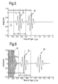
- Figure 5 shows simulated data comprising surface wave amplitudes transmitted through an anisotropic object plotted against time at a distance d from a transducer which produces an ultrasonic wave 31 having a pulse length / duration t w .
- surface waves generated by a surface mounted transducer comprise a number of different wave types, in particular, longitudinal surface waves 32 and Rayleigh waves 34. These different wave types initially overlap, and then spread out as the wave travels from the transducer 22 across the surface of the object 10. This is because the different wave types travel at different speeds.
- the longitudinal surface wave 32 has been found to have a higher velocity c L in a given material compared to the velocity c R of the Rayleigh waves, and so the longitudinal surface wave 32 arrives at the distance d earliest in the time-trace, while the lower velocity Rayleigh wave 34 arrives later, as shown in Figure 5 .
- the waves 32, 34 need to be separated from one another at the distance d.
- the pulse-length t w is approximately the number of cycles n in the ultrasonic wave 31 divided by the centre frequency f c of the wave 31: t w ⁇ n f c
- the above equation gives the minimum distance d min that the transducer 22 and the detector 26a in the array 24 which is closest to the transducer 22 have to be separated to ensure the signals are time resolvable and hence an accurate velocity measurement, and therefore crystallographic orientation measurement, can be made.
- the distance between the transducer 22 and the detector 26a may be less than the minimum distance, and as such the longitudinal and Rayleigh waves 32, 34 become hard to distinguish from one another, resulting in a high apparent noise to signal ratio.
- the maximum distance is limited by the component size.
- a larger d min will correspond to a smaller range of angles over which the velocity profile is measured for an array 24 having a given width r. Measuring the angles over a smaller range will reduce the orientation measurement accuracy. As a result, the distance d min should be as small as possible, while being at least the smallest value that allows the signals to be time resolvable.
- the times of flight t L , t R of the surface waves 32, 34 are dependent somewhat on the direction of travel of the waves 32, 34 relative to the crystallographic orientation of the material. Since at this point in the method the crystallographic orientation is unknown, the distance d min is determined on the basis of the minimum time of flight t R of the Rayleigh waves 34, and the maximum time of flight t L of the longitudinal waves 32, i.e. the time of flight where the direction of travel of the respective wave 32, 34 relative to the crystallographic orientation results in the highest Rayleigh wave velocity c R , and the lowest longitudinal wave velocity c L . In this way, when the assembly 20 is used to measure the crystallographic orientation of an object, the Rayleigh and longitudinal waves 32, 34 are separated in the time trace where the detector 26a and the transducer 22 are separation by d min .
- the above example assumes that there is no "ringing" due to electrical and mechanical coupling or "cross-talk” between the transducer 22 and detectors 26.
- the assembly is configured such that they are electrically and / or mechanically isolated from each other as far as possible in order to minimise the cross-talk.
- a barrier (not shown) made of highly attenuating material is placed between the transducer 22 and the detector array 24.
- the transducer 22 and the detector array 24 are electrically shielded by covering their two housings in an electrically conductive paint.
- any practical crystallographic orientation measurement assembly 20 there will always be a finite amount of ring-down (as represented by wave 33 in Figure 6 ), as the transducer 22 and detectors 26 can never be completely mechanically and electrically decoupled.
- Figure 6 shows simulated data comprising surface wave amplitudes transmitted through an anisotropic object plotted against time at a distance d from a transducer which produces an ultrasonic wave, where the transducer 22 and detectors 26 are not wholly mechanically and electrically decoupled.
- Equation 2 c L ⁇ t rd + n 2 ⁇ f c
- the minimum distance d min between the transducer 20 and the detector 26a in the array 24 which is closest to the transducer 22 is given by the greater value of Equations 6 and 8 and is thus dependent on the velocity of the ultrasonic waves 32, 34 and the duration of the ring-down t rd .
- d min may be found experimentally for a given material or batch of components.
- the object to be measured is a single crystal turbine blade 10 comprising a nickel based superalloy such as CMSX-4
- d min has been found to be approximately 3mm where the surface wave generated by the transducer 22 has a frequency of 5 MHz.
- CMSX-4 is a high Nickel content alloy having the following composition by weight: Nickel: 61.7%, Cobalt: 9%, Chromium: 6.5%, Tantalum: 6.5%, Tungsten: 6%, Aluminium: 5.6, Rhenium: 3%, Titanium: 1%, Molybdenum: 0.6%, Hafnium: 0.1%.
- the assembly 20 can be used to determine the crystallographic orientation of an object such as a turbine blade 10 as follows.
- the minimum separation distance d min is first determined.
- d min may be determined experimentally, by measuring the longitudinal and Rayleigh wave velocities c L , c R and ring down time t rd , and using equations 6 and 8 to determine d min for the object to be measured, or for a batch of object.
- d min may be determined separately for a particular material and provided to the user in a look up table. The user can then use the appropriate minimum separation on the basis of the look up table.
- the user places the transducer 22 and the detector array 24 on the surface 14 of the blade 10 such that the distance between the detector 26a of the detector array 24 closest to the transducer 22 is at least d min .
- the detector array 24 may be placed a greater distance from the transducer 22 than d min .
- d min therefore represents the closest distance that the transducer 22 and the detector 26a can be placed while providing a reliable indication of wave velocities and therefore crystallographic orientation.
- the casing 25 may be configured such that the transducer 22 and the detector array 24 are separated by at least the required distance d min for a predetermined experimental set up for a particular material to be measured.
- the casing 25 may also be adjustable such that an appropriate separation can be selected for a particular material on the basis of the lookup table or experimentation using a calibration procedure. The calibration procedure could be used in addition to the lookup table to account for manufacturing variations.
- the controller 30 is then actuated to generate a voltage spike (as described above) to the transducer 22 such that the transducer 22 produces an ultrasonic signal having a required centre frequency f c .
- the surface waves 32, 34 then travel across the surface 14 of the blade 10, as shown by the arrows W in Figure 3 .
- the detectors are caused to generate a signal which is transmitted to the controller 30.
- the controller 30 records the times at which the surface waves 32, 34 are received at each detector 26 to produce time of flight data.
- the time of flight data could comprise both the longitudinal and Rayleigh waves 32, 34. It has been found that more accurate results can be determined using only the longitudinal surface waves 32.
- the crystallographic orientation of the blade 10 can then be determined using this data as follows.
- An initial estimate of the crystallographic orientation of the blade 10 is made to compute the velocity profile relative to the array 24.
- a propagation model uses this velocity profile to compute the time of flight data.
- the measured and computed time of flight data are then compared to find the global error for the estimated orientation.
- the process is then repeated with different orientations until the global error is minimised.
- the orientation at which the global error is minimised therefore corresponds to the crystallographic orientation of the material.
- the same assembly 20 can then be used to detect defects such as cracks 12.
- the array 24 is used to generate bulk waves in the blade 10 (since the transducer 22 is configured to only produce surface waves).
- the reflected bulk waves can be detected by the detector array 24 to detect defects using conventional ultrasonic techniques.
- the invention therefore provides an assembly and a method of measuring a crystallographic orientation in an anisotropic material such as a directionally solidified or single crystal alloy turbine blade.
- the same assembly can also be used to detect subsurface defects in the object, thereby reducing time and costs.
- the assembly and method can be used to determine the location of defects to a relatively high degree of precision due to the high resolution of the detector array.
Landscapes
- Physics & Mathematics (AREA)
- Health & Medical Sciences (AREA)
- Life Sciences & Earth Sciences (AREA)
- Chemical & Material Sciences (AREA)
- Analytical Chemistry (AREA)
- Biochemistry (AREA)
- General Health & Medical Sciences (AREA)
- General Physics & Mathematics (AREA)
- Immunology (AREA)
- Pathology (AREA)
- Acoustics & Sound (AREA)
- Investigating Or Analyzing Materials By The Use Of Ultrasonic Waves (AREA)
Abstract
• determining a minimum distance (dmin) between the transducer (22) and the detector (26a) of the detector array (24) closest to the transducer (22);
• placing the transducer (22) and the detector array (24) in contact with a surface (14) of the object (10) such that the transducer (22) and the detector (26a) of the detector array (24) closest to the transducer (22) are separated by at least the minimum distance (dmin);
• using the transducer (22) to generate an ultrasonic surface wave pulse in the surface (14) of the object, the ultrasonic surface wave pulse having a pulse duration (tw) and comprising a longitudinal surface wave (32) and a Rayleigh wave (34); and
• measuring a time of flight of a surface wave generated by the transducer (22) between the transducer (22) and each detector (26) of the array (24) to determine the crystallographic orientation (X, Y, Z) of the object (10).

Description
- The present invention relates to a method of measuring a crystallographic orientation of an object, and an assembly for measuring a crystallographic orientation of an object.
- Ultrasonic defect inspection assemblies and methods are known for inspecting objects such as gas turbine engine components and the like for defects such as cracks, inclusions and porosity.
- Prior ultrasonic inspection methods comprise using an ultrasonic wave generator (transducer) and one or more ultrasonic wave detectors separated by a known difference to measure the time-of-flight of propagating ultrasonic waves along known ray-paths to determine the velocity of the ultrasonic waves and therefore the local density and other properties of the material. In some materials, known as "isotropic" materials, the wave velocity is substantially constant in all directions. However, some materials, such as single crystal or directionally solidified metals or alloys, exhibit anisotropic properties due for example to the orientation of the crystal, such that the wave velocity varies according to direction of wave propagation. In order to reliably inspect objects comprising anisotropic materials, the orientation of the crystal must therefore be determined prior to defect inspection.
- Ultrasonic inspection methods can be used to determine crystal orientation and therefore wave propagation velocity anisotropy by propagating ultrasonic waves along known ray paths in a number of directions. From these velocity measurements, a prediction of the crystallographic orientation can be made. A number of different ultrasonic methods have been devised. A first method, as described for example in
US 4106327 , uses a transducer located on one surface of the object and a detector located on an opposite surface to measure the velocity of bulk ultrasonic waves through the object. However, the method described inUS 4106327 requires access to both sides of the object. A second method, such as that described inUS 5955671 utilises reflectors in the object having known locations and reflective properties to reflect the wave generated by the transducer back to a detector located on the same face as the transducer (known as "pulse-echo" or "pitch-catch"). This is not always possible, since such known reflectors may not be present, which is the case for in situ inspections of gas turbine engine components for example. - A third orientation method has been suggested which comprises using ultrasonic surface-waves. Such a method would have the advantage of only requiring access to a single face of the material to perform the measurement without requiring the presence of a known reflector within the object. However, such methods have not previously been successful using conventional detector arrays, since the signals received by the detectors have been found to have a low signal to noise ratio. As such, the wave velocity of the surface-waves can often not be measured, and hence the orientation cannot be predicted accurately.
- The present invention provides a ultrasonic inspection assembly which seeks to overcome these disadvantages.
- According to a first aspect of the present invention there is provided a method of measuring a crystallographic orientation of an object using an ultrasonic transducer and a detector array comprising a plurality of ultrasonic detectors, the method comprising:
- determining a minimum distance (dmin) between the transducer and a detector of the detector array closest to the transducer;
- placing the transducer and the detector array in contact with a surface of the object such that the transducer and the detector of the detector array closest to the transducer are separated by at least the minimum distance (dmin);
- using the transducer to generate an ultrasonic surface wave pulse in the surface of the object, the ultrasonic surface wave pulse having a pulse duration (tw) and comprising a longitudinal surface wave and a Rayleigh wave; and measuring a time of flight of a surface wave generated by the transducer between the transducer and each detector of the array to determine the crystallographic orientation of the object;
- The invention is enabled by the realisation that the signal to noise ratio can be increased by specifying a minimum distance (dmin) between the transducer and the closest of the detectors in the detector array. The minimum distance has been found to comprise the distance at which the minimum time of flight of the Rayleigh wave (tR) is at least the sum of the maximum time of flight of the longitudinal surface wave (tL) and the maximum pulse duration (tw). By determining the minimum separation distance in this manner, the separation distance between the detectors can be chosen on the basis of a required resolution, while minimising signal noise.
- The ultrasonic surface wave pulse may have a centre frequency (fc) and a pulse length (n) cycles, the longitudinal surface wave may have a minimum velocity in the object (cL), and the Rayleigh wave may have a maximum velocity in the object (cR). The minimum distance (dmin) may be determined by the formula:

- The detector array may have a ring down time (trd). The distance (dmin) may be determined by the greater value of dmin determined by the formulas:

and;
- The ultrasonic surface wave pulse may have a frequency in
range 1 MHz to 15MHz, and may have a frequency of approximately 5MHz. - The object may comprise a nickel based alloy, and may comprise CMSX-4 alloy. The object may comprise a component of a gas turbine engine such as a turbine blade.
- The detector array may comprise a 1-d array in which the detectors are arrayed in a row. Alternatively, the detector array may comprise a 2-d array in which the detectors are arrayed in at least two rows.
- According to a second aspect of the invention there is provided crystallographic orientation measurement assembly, the assembly comprising:
- an object having a crystallographic orientation;
- an ultrasonic transducer configured to generate an ultrasonic surface wave pulse having a pulse duration (tw), the ultrasonic surface wave pulse comprising a longitudinal surface wave and a Rayleigh wave; and
- a detector array comprising a plurality of ultrasonic detectors; wherein the transducer and the detector of the detector array closest to the transducer are separated by at least a minimum distance (dmin), wherein the minimum distance (dmin) is the distance at which the minimum time of flight of the Rayleigh wave (tR) is at least the sum of the maximum time of flight of the longitudinal surface wave (tL) and the maximum pulse duration (tw).
- Embodiments of the invention will now be described by way of example with reference to the accompanying drawings in which:
-
Figure 1a shows a perspective view of a directionally solidified turbine blade; -
Figure 1b shows a perspective view of a single crystal turbine blade; -
Figure 2 shows a cross sectional view of a part of the turbine blade ofFigure 1 and a crystallographic orientation measurement assembly; -
Figure 3 shows a plan view of the assembly ofFigure 2 ; -
Figure 4 shows a plan view of an alternative crystallographic orientation measurement assembly; -
Figure 5 shows a graph of surface wave amplitudes plotted against time at a point on an object for an ideal mechanically and electrically shielded crystallographic orientation measurement assembly; and -
Figure 6 shows a graph of surface wave amplitudes plotted against time at a point on an object for a crystallographic orientation measurement assembly having mechanical and / or electrical cross talk between components of the assembly. -
Figures 1a and b show turbine blades turbine blades turbine blade Figure 1a by the arrow X, as shown in detail in the enlarged view ofFigure 1a . However, single crystal alloy blades, such as that shown inFigure 1b have a cubic anisotropy, i.e. the crystal orientation has to be computed around the X, Y and Z axes. -
Figure 2 shows a radial cross sectional view of part of theturbine blade 10 ofFigure 1 . The blade includes acrack 12 located underneath asurface 14 of theblade 10. - In
Figure 2 , a crystallographicorientation measurement assembly 20 is in contact with thesurface 14 of theblade 10. The crystallographicorientation measurement assembly 20 comprises anultrasonic transducer 22 and adetector array 24, each being in contact with the surface of theblade 10. In this embodiment, thetransducer 22 and thedetector array 24 are housed within acasing 25, though in some cases the casing may not be provided. - The
transducer 22 is configured to generate surface ultrasonic waves in thesurface 14 of theblade 10 and is mounted to thesurface 14 at an angle θ to thesurface 14 by awedge 23 made of an ultrasonic transmissive material such as Perspex. The ultrasonic waves produced by thetransducer 22 are transmitted through thewedge 23 to thesurface 14 of the component at an incident angle θI. This ensures that a required surface wave is generated with maximum efficiency. For example, where the required surface wave is a Rayleigh wave, the incident angle θI for producing Rayleigh waves at maximum efficiency is given by the formula:
- Where VR represents the Rayleigh wave velocity in the material of the object to be measure (i.e. the
blade 10 in this example) and VI represents the incident wave velocity in the material of the wedge, which in this example comprises Perspex™. The generation of the surface wave may not be 100% efficient however, such that some bulk waves are produced by thetransducer 22. The wedge may be shaped such that the transducer is mounted to theblade 10 at a preset angle θI which corresponds to the above formula for a particular known material. Alternatively, thewedge 23 may be adjustable such that theassembly 20 can be used for objects comprising different materials. - The
ultrasonic transducer 22 is generally configured to produce surface waves having a frequency of between 1 MHz and 15MHz, and preferably a frequency of approximately 5 MHz, though different frequencies may be used depending on various conditions, and the properties of the material under investigation. For example, firstly the ring down frequency of single crystal Nickel super alloys (i.e. the material that turbine blades are normally formed of) has been found to be 10 MHz. By choosing a frequency that is substantially higher or lower than this frequency, the noise can be reduced. Secondly, as shown below, the minimum separation between thetransducer 22 and thedetector array 24 that provides high accuracy is dependent on the frequency used. A higher frequency will generally result in a smaller minimum separation. Thirdly, the frequency generated by thetransducer 22 should be matched to the receiving frequency response of the detectingarray 24. Most commercially available ultrasonic detectors have a frequency response in the range 5 to 15 MHz, with a peak detection efficiency of around 10 MHz. A frequency of 5 MHZ is therefore chosen in order to obtain a good compromise between each of these requirements. - As shown in detail in
Figure 3 , thedetector array 24 comprises a plurality ofultrasonic detectors 26 arranged in a plurality ofrows 28. Such an arrangement is known as a "2-d" array. One example of a suitable 2-d detector array is provided by Imasonic™ of Besancon, France. An example of a "1-d" array is shown inFigure 4 , and comprises asingle row 28 ofultrasonic detectors 26. Each of thedetectors 26 is configured to detect the surface waves generated by thetransducer 22. Thedetectors 26 are configured to send a signal representative of the amplitude of the wave to a controller 30 (described in greater detail below). - The centre of each of the
detectors 26 in thearray 24 is separated from theadjacent detectors 26 in eachrow 28 by a known distance a, and eachrow 28 is separated by a known distance b. The physical size of thearray 24 is therefore related to the distances a and b, and the number ofdetectors 26 in thearray 24. Generally, the resolution and focusing ability of the array is proportional to the total aperture, i.e. size of the array. In other words, the resolution of thedetector array 24 is proportional to the number ofdetectors 26 in thearray 24, and the distance between thedetectors 26, known as "pitch". The resolution can therefore be increased by either increasing the number ofdetectors 26 in thearray 24, or by increasing the pitch. However, the number ofdetectors 26 in thearray 24 is limited by the number of channels in thecontroller 30. On the other hand, beyond a certain value, an increase in pitch will lead to "side lobes", also known as "grating lobes" being generated in addition to the main lobe as a result of thedetector array 24 acting as a diffraction grating. Such grating lobes may result in image artefacts and consequently a reduction in resolution. Grating lobes can be avoided or minimised by limiting the pitch to half a wavelength of the surface waves generated by thetransducer 22. The wavelength is given by the wave velocity in the material under investigation divided by the frequency of the surface waves. In this example therefore, where the frequency generated by thetransducer 22 is approximately 5 MHz and the wave velocity is approximately 6000 metres per second, the pitch, i.e. distances a and b are both approximately 0.6 mm. Where the frequency generated by thetransducer 22 is approximately 10 MHz, the pitch is approximately 0.3 mm. - Each
detector 26 in thedetector array 24 is separated from thetransducer 22 by a distance d. The distance d varies for eachdetector 26, from a minimum value dmin for thedetector 26a in thearray 24 which is closest to thetransducer 22, to a maximum value dmax for thedetector 26b in thearray 24 which is furthest from thetransducer 22. - The
transducer 22 anddetector array 24 are each connected to thecontroller 30, as shown diagrammatically inFigure 2 . Thecontroller 30 is electrically connected to thetransducer 22 and eachdetector 26 of thearray 24. Thecontroller 30 provides a single voltage spike or a half-cycle square wave to the transducer. This causes the transducer element to vibrate at its resonant frequency. The pulse length is controlled by a damping material provided on the back of thetransducer 22, i.e. on the side of the transducer that does not come into contact with thewedge 23. Thecontroller 30 also receives signals representing the amplitude of the surface and bulk waves detected by thedetectors 26. An example of asuitable controller 30 is the Micropulse™ MP5PA array controller manufactured by Peak NDT Ltd of Derby, UK. This controller is has been chosen, as is provides fully parallel channels, rather than using multiplexing to aggregate the signals from each of thedetectors 26 in thearray 24 into a single signal. This allows signals fromindividual detectors 26 to be recorded, which allows a crystallographic orientation to be determined. - The crystallographic orientation of an object such as the
blade 10 can be determined using the crystallographicorientation measurement assembly 20 using the following method. - First, the distance dmin between the
transducer 22 and thedetector 26a in thearray 24 which is closest to thetransducer 22 must be determined using the following method. -
Figure 5 shows simulated data comprising surface wave amplitudes transmitted through an anisotropic object plotted against time at a distance d from a transducer which produces anultrasonic wave 31 having a pulse length / duration tw. It has been found that surface waves generated by a surface mounted transducer comprise a number of different wave types, in particular, longitudinal surface waves 32 and Rayleigh waves 34. These different wave types initially overlap, and then spread out as the wave travels from thetransducer 22 across the surface of theobject 10. This is because the different wave types travel at different speeds. Thelongitudinal surface wave 32 has been found to have a higher velocity cL in a given material compared to the velocity cR of the Rayleigh waves, and so thelongitudinal surface wave 32 arrives at the distance d earliest in the time-trace, while the lowervelocity Rayleigh wave 34 arrives later, as shown inFigure 5 . - For accurate velocity measurement at a distance d of either the longitudinal 32 or
Rayleigh 34 waves, thewaves 
- The times-of-flight of the transmitted waves 32, 34 are given by the distance d between the
transducer 22 and therespective detectors 26, and the velocity c of thewaves 

where the subscripts L and R refer to the longitudinal and Rayleigh waves respectively. - The pulse-length tw is approximately the number of cycles n in the
ultrasonic wave 31 divided by the centre frequency fc of the wave 31:
- Therefore, substituting Equations 2-4 into
Equation 1 yields:
- Arranging the above equation to make the distance the subject yields:

- Therefore, the above equation gives the minimum distance dmin that the
transducer 22 and thedetector 26a in thearray 24 which is closest to thetransducer 22 have to be separated to ensure the signals are time resolvable and hence an accurate velocity measurement, and therefore crystallographic orientation measurement, can be made. In contrast, in previous methods, where no minimum distance dmin is determined, the distance between thetransducer 22 and thedetector 26a may be less than the minimum distance, and as such the longitudinal andRayleigh waves - On the other hand, the maximum distance is limited by the component size. Generally, as will be understood from basic trigonometry, the range of angles Δα over which the velocity profile is measured for an
array 24 having a given width r (i.e. the distance a times the number of detectors 26) is related to dmin:
- As will be understood from the above equation, a larger dmin will correspond to a smaller range of angles over which the velocity profile is measured for an
array 24 having a given width r. Measuring the angles over a smaller range will reduce the orientation measurement accuracy. As a result, the distance dmin should be as small as possible, while being at least the smallest value that allows the signals to be time resolvable. - In anisotropic materials, the times of flight tL, tR of the surface waves 32, 34 are dependent somewhat on the direction of travel of the
waves longitudinal waves 32, i.e. the time of flight where the direction of travel of therespective wave assembly 20 is used to measure the crystallographic orientation of an object, the Rayleigh andlongitudinal waves detector 26a and thetransducer 22 are separation by dmin. - The above example assumes that there is no "ringing" due to electrical and mechanical coupling or "cross-talk" between the
transducer 22 anddetectors 26. The assembly is configured such that they are electrically and / or mechanically isolated from each other as far as possible in order to minimise the cross-talk. For example, a barrier (not shown) made of highly attenuating material is placed between thetransducer 22 and thedetector array 24. Thetransducer 22 and thedetector array 24 are electrically shielded by covering their two housings in an electrically conductive paint. However, in any practical crystallographicorientation measurement assembly 20 there will always be a finite amount of ring-down (as represented bywave 33 inFigure 6 ), as thetransducer 22 anddetectors 26 can never be completely mechanically and electrically decoupled. -
Figure 6 shows simulated data comprising surface wave amplitudes transmitted through an anisotropic object plotted against time at a distance d from a transducer which produces an ultrasonic wave, where thetransducer 22 anddetectors 26 are not wholly mechanically and electrically decoupled. - To ensure sufficient separation of the longitudinal 32 and
Rayleigh 34 waves in this case, the time-of-flight of thelongitudinal wave 32 has to be at least the ring-down time, trd, plus half the pulse-length tw, thus:
- Substituting
Equation 2 and 4 into Equation 7 and rearranging for distance yields:
- Thus, the minimum distance dmin between the
transducer 20 and thedetector 26a in thearray 24 which is closest to thetransducer 22 is given by the greater value of Equations 6 and 8 and is thus dependent on the velocity of theultrasonic waves - In practical terms, dmin may be found experimentally for a given material or batch of components. In one example, where the object to be measured is a single
crystal turbine blade 10 comprising a nickel based superalloy such as CMSX-4, dmin has been found to be approximately 3mm where the surface wave generated by thetransducer 22 has a frequency of 5 MHz. CMSX-4 is a high Nickel content alloy having the following composition by weight: Nickel: 61.7%, Cobalt: 9%, Chromium: 6.5%, Tantalum: 6.5%, Tungsten: 6%, Aluminium: 5.6, Rhenium: 3%, Titanium: 1%, Molybdenum: 0.6%, Hafnium: 0.1%. - The
assembly 20 can be used to determine the crystallographic orientation of an object such as aturbine blade 10 as follows. - The minimum separation distance dmin is first determined. dmin may be determined experimentally, by measuring the longitudinal and Rayleigh wave velocities cL, cR and ring down time trd, and using equations 6 and 8 to determine dmin for the object to be measured, or for a batch of object. Alternatively, dmin may be determined separately for a particular material and provided to the user in a look up table. The user can then use the appropriate minimum separation on the basis of the look up table.
- Once dmin has been determined, the user then places the
transducer 22 and thedetector array 24 on thesurface 14 of theblade 10 such that the distance between thedetector 26a of thedetector array 24 closest to thetransducer 22 is at least dmin. In some cases, thedetector array 24 may be placed a greater distance from thetransducer 22 than dmin. dmin therefore represents the closest distance that thetransducer 22 and thedetector 26a can be placed while providing a reliable indication of wave velocities and therefore crystallographic orientation. In some cases, thecasing 25 may be configured such that thetransducer 22 and thedetector array 24 are separated by at least the required distance dmin for a predetermined experimental set up for a particular material to be measured. Thecasing 25 may also be adjustable such that an appropriate separation can be selected for a particular material on the basis of the lookup table or experimentation using a calibration procedure. The calibration procedure could be used in addition to the lookup table to account for manufacturing variations. - Once the
assembly 20 is placed in contact with thesurface 14, thecontroller 30 is then actuated to generate a voltage spike (as described above) to thetransducer 22 such that thetransducer 22 produces an ultrasonic signal having a required centre frequency fc. Thecontroller 30 records the time at which the signal is sent, which can be represented at t = 0. - The surface waves 32, 34 then travel across the
surface 14 of theblade 10, as shown by the arrows W inFigure 3 . When thewaves respective detectors 26 in thearray 24, the detectors are caused to generate a signal which is transmitted to thecontroller 30. Thecontroller 30 records the times at which the surface waves 32, 34 are received at eachdetector 26 to produce time of flight data. The time of flight data could comprise both the longitudinal andRayleigh waves - The crystallographic orientation of the
blade 10 can then be determined using this data as follows. An initial estimate of the crystallographic orientation of theblade 10 is made to compute the velocity profile relative to thearray 24. A propagation model uses this velocity profile to compute the time of flight data. The measured and computed time of flight data are then compared to find the global error for the estimated orientation. The process is then repeated with different orientations until the global error is minimised. The orientation at which the global error is minimised therefore corresponds to the crystallographic orientation of the material. - The
same assembly 20 can then be used to detect defects such as cracks 12. Thearray 24 is used to generate bulk waves in the blade 10 (since thetransducer 22 is configured to only produce surface waves). The reflected bulk waves can be detected by thedetector array 24 to detect defects using conventional ultrasonic techniques. - The invention therefore provides an assembly and a method of measuring a crystallographic orientation in an anisotropic material such as a directionally solidified or single crystal alloy turbine blade. The same assembly can also be used to detect subsurface defects in the object, thereby reducing time and costs. Furthermore, the assembly and method can be used to determine the location of defects to a relatively high degree of precision due to the high resolution of the detector array.
- While the invention has been described in conjunction with the exemplary embodiments described above, many equivalent modifications and variations will be apparent to those skilled in the art when given this disclosure. Accordingly, the exemplary embodiments of the invention set forth above are considered to be illustrative and not limiting. Various changes to the described embodiments may be made without departing from the spirit and scope of the invention.
Claims (11)
- A method of measuring a crystallographic orientation of an object 10 using an ultrasonic transducer 22 and a detector array 24 comprising a plurality of ultrasonic detectors 26, the method comprising:determining a minimum distance (dmin) between the transducer 22 and a detector 26 of the detector array 24 closest to the transducer 22;placing the transducer 22 and the detector array 24 in contact with a surface of the object 10 such that the transducer 22 and the detector of the detector array 24 closest to the transducer 22 are separated by at least the minimum distance (dmin);using the transducer 22 to generate an ultrasonic surface wave pulse in the surface of the object 10, the ultrasonic surface wave pulse having a pulse duration (tw) and comprising a longitudinal surface wave and a Rayleigh wave; andmeasuring a time of flight of a surface wave generated by the transducer 22 between the transducer 22 and each detector 26 of the array 24 to determine the crystallographic orientation of the object 10;wherein the minimum distance (dmin) is the distance at which the minimum time of flight of the Rayleigh wave (tR) is at least the sum of the maximum time of flight of the longitudinal surface wave (tL) and the maximum pulse duration (tw).
- A method according to claim 1, where the ultrasonic surface wave pulse has a centre frequency (fc) and a pulse length (n) cycles, the longitudinal surface wave has a minimum velocity in the object (cL), and the Rayleigh wave has a maximum velocity in the object (cR), wherein the minimum distance (dmin) is determined by the formula:

- A method according to claim 2, wherein the detector array 24 has a ring down time (trd), and the distance (dmin) is determined by the greater value of dmin determined by the formulas:

and;
- A method according to any of the preceding claims, wherein the ultrasonic surface wave pulse has a frequency in range 1 MHz to 15MHz.
- A method according to claim 4, wherein the ultrasonic surface wave pulse has a frequency of approximately 5MHz.
- A method according to any of the preceding claims, wherein the object 10 comprises a nickel based alloy.
- A method according to any of the preceding claims, wherein the object 10 is a component of a gas turbine engine.
- A method according to claim 7, wherein the component is a turbine blade 10.
- A method according to any of the preceding claims, wherein the detector array 24 comprises a 1-d array in which the detectors 26 are arrayed in a row.
- A method according to any of the preceding claims, wherein the detector array 24 comprises a 2-d array in which the detectors 26 are arrayed in at least two rows.
- A crystallographic orientation measurement assembly, the assembly comprising:an object 10 having a crystallographic orientation;an ultrasonic transducer 22 configured to generate an ultrasonic surface wave pulse having a pulse duration (tw), the ultrasonic surface wave pulse comprising a longitudinal surface wave and a Rayleigh wave; anda detector array 24 comprising a plurality of ultrasonic detectors 26; wherein the transducer 22 and the detector 26 of the detector array 24 closest to the transducer 22 are separated by at least a minimum distance (dmin), wherein the minimum distance (dmin) is the distance at which the minimum time of flight of the Rayleigh wave (tR) is at least the sum of the maximum time of flight of the longitudinal surface wave (tL) and the maximum pulse duration (tw).
Applications Claiming Priority (1)
| Application Number | Priority Date | Filing Date | Title |
|---|---|---|---|
| GBGB1211373.4A GB201211373D0 (en) | 2012-06-27 | 2012-06-27 | Method of measuring a crystallo-graphic orientation of an object |
Publications (3)
| Publication Number | Publication Date |
|---|---|
| EP2679994A2 true EP2679994A2 (en) | 2014-01-01 |
| EP2679994A3 EP2679994A3 (en) | 2017-12-06 |
| EP2679994B1 EP2679994B1 (en) | 2018-12-19 |
Family
ID=46704274
Family Applications (1)
| Application Number | Title | Priority Date | Filing Date |
|---|---|---|---|
| EP13171860.3A Active EP2679994B1 (en) | 2012-06-27 | 2013-06-13 | Method and assembly for measuring a crystallographic orientation of an object |
Country Status (3)
| Country | Link |
|---|---|
| US (1) | US9366654B2 (en) |
| EP (1) | EP2679994B1 (en) |
| GB (1) | GB201211373D0 (en) |
Cited By (1)
| Publication number | Priority date | Publication date | Assignee | Title |
|---|---|---|---|---|
| CN104483385A (en) * | 2014-12-05 | 2015-04-01 | 中国航空工业集团公司北京航空材料研究院 | Method for measuring longitudinal wave velocity of anisotropic material |
Families Citing this family (2)
| Publication number | Priority date | Publication date | Assignee | Title |
|---|---|---|---|---|
| CN108037187A (en) * | 2017-12-05 | 2018-05-15 | 南京航空航天大学 | Airfield runway based on Rayleigh waves comes to nothing monitoring method |
| GB202112995D0 (en) * | 2021-09-13 | 2021-10-27 | Rolls Royce Plc | System and method for testing of monocrystalline components |
Family Cites Families (5)
| Publication number | Priority date | Publication date | Assignee | Title |
|---|---|---|---|---|
| US4106327A (en) | 1977-11-22 | 1978-08-15 | The United States Of America As Represented By The United States Department Of Energy | Anisotropic determination and correction for ultrasonic flaw detection by spectral analysis |
| US5467655A (en) * | 1991-03-27 | 1995-11-21 | Nippon Steel Corporation | Method for measuring properties of cold rolled thin steel sheet and apparatus therefor |
| GB9510032D0 (en) * | 1995-05-18 | 1995-07-12 | Atomic Energy Authority Uk | Ultrasonic inspection |
| US5955671A (en) | 1997-03-28 | 1999-09-21 | General Electric Company | Method and apparatus for measurement of orientation in an anisotropic medium |
| EP1850126B1 (en) * | 2006-04-27 | 2012-07-11 | United Technologies Corporation | Systems and methods for determining the velocity of ultrasonic surface skimming longitudinal waves on various materials |
-
2012
- 2012-06-27 GB GBGB1211373.4A patent/GB201211373D0/en not_active Ceased
-
2013
- 2013-06-13 US US13/917,055 patent/US9366654B2/en active Active
- 2013-06-13 EP EP13171860.3A patent/EP2679994B1/en active Active
Cited By (2)
| Publication number | Priority date | Publication date | Assignee | Title |
|---|---|---|---|---|
| CN104483385A (en) * | 2014-12-05 | 2015-04-01 | 中国航空工业集团公司北京航空材料研究院 | Method for measuring longitudinal wave velocity of anisotropic material |
| CN104483385B (en) * | 2014-12-05 | 2017-02-22 | 中国航空工业集团公司北京航空材料研究院 | Method for measuring longitudinal wave velocity of anisotropic material |
Also Published As
| Publication number | Publication date |
|---|---|
| US20140000369A1 (en) | 2014-01-02 |
| GB201211373D0 (en) | 2012-08-08 |
| EP2679994A3 (en) | 2017-12-06 |
| EP2679994B1 (en) | 2018-12-19 |
| US9366654B2 (en) | 2016-06-14 |
Similar Documents
| Publication | Publication Date | Title |
|---|---|---|
| EP2639581B1 (en) | Ultrasonic inspection method | |
| US7272529B2 (en) | Dual wall turbine blade ultrasonic wall thickness measurement technique | |
| US7900516B2 (en) | Ultrasonic flaw detection apparatus and ultrasonic flaw detection method | |
| US20070000328A1 (en) | Ultrasonic method for the accurate measurement of crack height in dissimilar metal welds using phased array | |
| CA2593893C (en) | Improved technique and phased array transducer for ultrasonic inspection of coarse grained, anisotropic welds | |
| US4441369A (en) | Ultrasonic detection of extended flaws | |
| CN101490543A (en) | Ultrasonic flaw detection device and method | |
| EP2679994B1 (en) | Method and assembly for measuring a crystallographic orientation of an object | |
| EP2972289B1 (en) | Ultrasonic examination of components with unknown surface geometries | |
| EP1677106A2 (en) | Ultrasonic probe and inspection method and system | |
| RU2651431C1 (en) | Method of industrial ultrasound diagnostics of vertically oriented defects of prismatic metal products and device for its implementation | |
| Fromme et al. | Remote Monitoring of Plate‐Like Structures Using Guided Wave Arrays | |
| Bolotina et al. | 3D Ultrasonic Imaging by Cone Scans and Acoustic Antennas | |
| Massaad et al. | Acoustic design of a transducer array for ultrasonic clamp-on flow metering | |
| EP1850126B1 (en) | Systems and methods for determining the velocity of ultrasonic surface skimming longitudinal waves on various materials | |
| Margetan et al. | Ultrasonic signal attenuation in engine titanium alloys | |
| BIRRING | TOFD Principle, Limitations, Calibration and Inspection | |
| RU2740168C1 (en) | Method of determining reflector coordinate in section perpendicular to welded connection based on tofd-echo signals | |
| JPS59122944A (en) | Probe and ultrasonic wave flaw detecting method | |
| US6393917B1 (en) | System and method for ultrasonic image reconstruction using mode-converted Rayleigh wave | |
| Philtron et al. | Guided wave phased array sensor tuning for improved defect detection and characterization | |
| CA2544464A1 (en) | Ultrasonic determination of crystal grain orientation systems and methods for determining the velocity of ultrasonic surface skimming longitudinal waves on various materials | |
| Gudra et al. | Ultrasonic spectroscopy in non-destructive testing (NDT) of materials | |
| JP5904331B2 (en) | Array flaw detection apparatus and method | |
| Ibe | The Design and Simulation Patterns in Ultrasonic Wedges for Non-Destructive Testing |
Legal Events
| Date | Code | Title | Description |
|---|---|---|---|
| PUAI | Public reference made under article 153(3) epc to a published international application that has entered the european phase |
Free format text: ORIGINAL CODE: 0009012 |
|
| AK | Designated contracting states |
Kind code of ref document: A2 Designated state(s): AL AT BE BG CH CY CZ DE DK EE ES FI FR GB GR HR HU IE IS IT LI LT LU LV MC MK MT NL NO PL PT RO RS SE SI SK SM TR |
|
| AX | Request for extension of the european patent |
Extension state: BA ME |
|
| RAP1 | Party data changed (applicant data changed or rights of an application transferred) |
Owner name: ROLLS-ROYCE PLC |
|
| PUAL | Search report despatched |
Free format text: ORIGINAL CODE: 0009013 |
|
| AK | Designated contracting states |
Kind code of ref document: A3 Designated state(s): AL AT BE BG CH CY CZ DE DK EE ES FI FR GB GR HR HU IE IS IT LI LT LU LV MC MK MT NL NO PL PT RO RS SE SI SK SM TR |
|
| AX | Request for extension of the european patent |
Extension state: BA ME |
|
| RIC1 | Information provided on ipc code assigned before grant |
Ipc: G01N 29/07 20060101AFI20171102BHEP Ipc: G01N 29/34 20060101ALI20171102BHEP |
|
| STAA | Information on the status of an ep patent application or granted ep patent |
Free format text: STATUS: REQUEST FOR EXAMINATION WAS MADE |
|
| 17P | Request for examination filed |
Effective date: 20180523 |
|
| RBV | Designated contracting states (corrected) |
Designated state(s): AL AT BE BG CH CY CZ DE DK EE ES FI FR GB GR HR HU IE IS IT LI LT LU LV MC MK MT NL NO PL PT RO RS SE SI SK SM TR |
|
| GRAP | Despatch of communication of intention to grant a patent |
Free format text: ORIGINAL CODE: EPIDOSNIGR1 |
|
| STAA | Information on the status of an ep patent application or granted ep patent |
Free format text: STATUS: GRANT OF PATENT IS INTENDED |
|
| GRAS | Grant fee paid |
Free format text: ORIGINAL CODE: EPIDOSNIGR3 |
|
| GRAA | (expected) grant |
Free format text: ORIGINAL CODE: 0009210 |
|
| STAA | Information on the status of an ep patent application or granted ep patent |
Free format text: STATUS: THE PATENT HAS BEEN GRANTED |
|
| INTG | Intention to grant announced |
Effective date: 20181029 |
|
| RIN1 | Information on inventor provided before grant (corrected) |
Inventor name: LANE, CHRISTOPHER |
|
| AK | Designated contracting states |
Kind code of ref document: B1 Designated state(s): AL AT BE BG CH CY CZ DE DK EE ES FI FR GB GR HR HU IE IS IT LI LT LU LV MC MK MT NL NO PL PT RO RS SE SI SK SM TR |
|
| REG | Reference to a national code |
Ref country code: GB Ref legal event code: FG4D |
|
| REG | Reference to a national code |
Ref country code: CH Ref legal event code: EP |
|
| REG | Reference to a national code |
Ref country code: IE Ref legal event code: FG4D |
|
| REG | Reference to a national code |
Ref country code: DE Ref legal event code: R096 Ref document number: 602013048346 Country of ref document: DE |
|
| REG | Reference to a national code |
Ref country code: AT Ref legal event code: REF Ref document number: 1079258 Country of ref document: AT Kind code of ref document: T Effective date: 20190115 |
|
| REG | Reference to a national code |
Ref country code: NL Ref legal event code: MP Effective date: 20181219 |
|
| PG25 | Lapsed in a contracting state [announced via postgrant information from national office to epo] |
Ref country code: NO Free format text: LAPSE BECAUSE OF FAILURE TO SUBMIT A TRANSLATION OF THE DESCRIPTION OR TO PAY THE FEE WITHIN THE PRESCRIBED TIME-LIMIT Effective date: 20190319 Ref country code: LT Free format text: LAPSE BECAUSE OF FAILURE TO SUBMIT A TRANSLATION OF THE DESCRIPTION OR TO PAY THE FEE WITHIN THE PRESCRIBED TIME-LIMIT Effective date: 20181219 Ref country code: FI Free format text: LAPSE BECAUSE OF FAILURE TO SUBMIT A TRANSLATION OF THE DESCRIPTION OR TO PAY THE FEE WITHIN THE PRESCRIBED TIME-LIMIT Effective date: 20181219 Ref country code: LV Free format text: LAPSE BECAUSE OF FAILURE TO SUBMIT A TRANSLATION OF THE DESCRIPTION OR TO PAY THE FEE WITHIN THE PRESCRIBED TIME-LIMIT Effective date: 20181219 Ref country code: HR Free format text: LAPSE BECAUSE OF FAILURE TO SUBMIT A TRANSLATION OF THE DESCRIPTION OR TO PAY THE FEE WITHIN THE PRESCRIBED TIME-LIMIT Effective date: 20181219 Ref country code: BG Free format text: LAPSE BECAUSE OF FAILURE TO SUBMIT A TRANSLATION OF THE DESCRIPTION OR TO PAY THE FEE WITHIN THE PRESCRIBED TIME-LIMIT Effective date: 20190319 |
|
| REG | Reference to a national code |
Ref country code: LT Ref legal event code: MG4D |
|
| REG | Reference to a national code |
Ref country code: AT Ref legal event code: MK05 Ref document number: 1079258 Country of ref document: AT Kind code of ref document: T Effective date: 20181219 |
|
| PG25 | Lapsed in a contracting state [announced via postgrant information from national office to epo] |
Ref country code: RS Free format text: LAPSE BECAUSE OF FAILURE TO SUBMIT A TRANSLATION OF THE DESCRIPTION OR TO PAY THE FEE WITHIN THE PRESCRIBED TIME-LIMIT Effective date: 20181219 Ref country code: AL Free format text: LAPSE BECAUSE OF FAILURE TO SUBMIT A TRANSLATION OF THE DESCRIPTION OR TO PAY THE FEE WITHIN THE PRESCRIBED TIME-LIMIT Effective date: 20181219 Ref country code: SE Free format text: LAPSE BECAUSE OF FAILURE TO SUBMIT A TRANSLATION OF THE DESCRIPTION OR TO PAY THE FEE WITHIN THE PRESCRIBED TIME-LIMIT Effective date: 20181219 Ref country code: GR Free format text: LAPSE BECAUSE OF FAILURE TO SUBMIT A TRANSLATION OF THE DESCRIPTION OR TO PAY THE FEE WITHIN THE PRESCRIBED TIME-LIMIT Effective date: 20190320 |
|
| PG25 | Lapsed in a contracting state [announced via postgrant information from national office to epo] |
Ref country code: NL Free format text: LAPSE BECAUSE OF FAILURE TO SUBMIT A TRANSLATION OF THE DESCRIPTION OR TO PAY THE FEE WITHIN THE PRESCRIBED TIME-LIMIT Effective date: 20181219 |
|
| PG25 | Lapsed in a contracting state [announced via postgrant information from national office to epo] |
Ref country code: IT Free format text: LAPSE BECAUSE OF FAILURE TO SUBMIT A TRANSLATION OF THE DESCRIPTION OR TO PAY THE FEE WITHIN THE PRESCRIBED TIME-LIMIT Effective date: 20181219 Ref country code: ES Free format text: LAPSE BECAUSE OF FAILURE TO SUBMIT A TRANSLATION OF THE DESCRIPTION OR TO PAY THE FEE WITHIN THE PRESCRIBED TIME-LIMIT Effective date: 20181219 Ref country code: PT Free format text: LAPSE BECAUSE OF FAILURE TO SUBMIT A TRANSLATION OF THE DESCRIPTION OR TO PAY THE FEE WITHIN THE PRESCRIBED TIME-LIMIT Effective date: 20190419 Ref country code: CZ Free format text: LAPSE BECAUSE OF FAILURE TO SUBMIT A TRANSLATION OF THE DESCRIPTION OR TO PAY THE FEE WITHIN THE PRESCRIBED TIME-LIMIT Effective date: 20181219 Ref country code: PL Free format text: LAPSE BECAUSE OF FAILURE TO SUBMIT A TRANSLATION OF THE DESCRIPTION OR TO PAY THE FEE WITHIN THE PRESCRIBED TIME-LIMIT Effective date: 20181219 |
|
| PG25 | Lapsed in a contracting state [announced via postgrant information from national office to epo] |
Ref country code: SK Free format text: LAPSE BECAUSE OF FAILURE TO SUBMIT A TRANSLATION OF THE DESCRIPTION OR TO PAY THE FEE WITHIN THE PRESCRIBED TIME-LIMIT Effective date: 20181219 Ref country code: RO Free format text: LAPSE BECAUSE OF FAILURE TO SUBMIT A TRANSLATION OF THE DESCRIPTION OR TO PAY THE FEE WITHIN THE PRESCRIBED TIME-LIMIT Effective date: 20181219 Ref country code: IS Free format text: LAPSE BECAUSE OF FAILURE TO SUBMIT A TRANSLATION OF THE DESCRIPTION OR TO PAY THE FEE WITHIN THE PRESCRIBED TIME-LIMIT Effective date: 20190419 Ref country code: EE Free format text: LAPSE BECAUSE OF FAILURE TO SUBMIT A TRANSLATION OF THE DESCRIPTION OR TO PAY THE FEE WITHIN THE PRESCRIBED TIME-LIMIT Effective date: 20181219 Ref country code: SM Free format text: LAPSE BECAUSE OF FAILURE TO SUBMIT A TRANSLATION OF THE DESCRIPTION OR TO PAY THE FEE WITHIN THE PRESCRIBED TIME-LIMIT Effective date: 20181219 |
|
| REG | Reference to a national code |
Ref country code: DE Ref legal event code: R097 Ref document number: 602013048346 Country of ref document: DE |
|
| PLBE | No opposition filed within time limit |
Free format text: ORIGINAL CODE: 0009261 |
|
| STAA | Information on the status of an ep patent application or granted ep patent |
Free format text: STATUS: NO OPPOSITION FILED WITHIN TIME LIMIT |
|
| PG25 | Lapsed in a contracting state [announced via postgrant information from national office to epo] |
Ref country code: DK Free format text: LAPSE BECAUSE OF FAILURE TO SUBMIT A TRANSLATION OF THE DESCRIPTION OR TO PAY THE FEE WITHIN THE PRESCRIBED TIME-LIMIT Effective date: 20181219 Ref country code: AT Free format text: LAPSE BECAUSE OF FAILURE TO SUBMIT A TRANSLATION OF THE DESCRIPTION OR TO PAY THE FEE WITHIN THE PRESCRIBED TIME-LIMIT Effective date: 20181219 |
|
| 26N | No opposition filed |
Effective date: 20190920 |
|
| PG25 | Lapsed in a contracting state [announced via postgrant information from national office to epo] |
Ref country code: MC Free format text: LAPSE BECAUSE OF FAILURE TO SUBMIT A TRANSLATION OF THE DESCRIPTION OR TO PAY THE FEE WITHIN THE PRESCRIBED TIME-LIMIT Effective date: 20181219 |
|
| REG | Reference to a national code |
Ref country code: CH Ref legal event code: PL |
|
| PG25 | Lapsed in a contracting state [announced via postgrant information from national office to epo] |
Ref country code: SI Free format text: LAPSE BECAUSE OF FAILURE TO SUBMIT A TRANSLATION OF THE DESCRIPTION OR TO PAY THE FEE WITHIN THE PRESCRIBED TIME-LIMIT Effective date: 20181219 |
|
| REG | Reference to a national code |
Ref country code: BE Ref legal event code: MM Effective date: 20190630 |
|
| PG25 | Lapsed in a contracting state [announced via postgrant information from national office to epo] |
Ref country code: TR Free format text: LAPSE BECAUSE OF FAILURE TO SUBMIT A TRANSLATION OF THE DESCRIPTION OR TO PAY THE FEE WITHIN THE PRESCRIBED TIME-LIMIT Effective date: 20181219 |
|
| PG25 | Lapsed in a contracting state [announced via postgrant information from national office to epo] |
Ref country code: IE Free format text: LAPSE BECAUSE OF NON-PAYMENT OF DUE FEES Effective date: 20190613 |
|
| PG25 | Lapsed in a contracting state [announced via postgrant information from national office to epo] |
Ref country code: LI Free format text: LAPSE BECAUSE OF NON-PAYMENT OF DUE FEES Effective date: 20190630 Ref country code: LU Free format text: LAPSE BECAUSE OF NON-PAYMENT OF DUE FEES Effective date: 20190613 Ref country code: CH Free format text: LAPSE BECAUSE OF NON-PAYMENT OF DUE FEES Effective date: 20190630 Ref country code: BE Free format text: LAPSE BECAUSE OF NON-PAYMENT OF DUE FEES Effective date: 20190630 |
|
| PG25 | Lapsed in a contracting state [announced via postgrant information from national office to epo] |
Ref country code: CY Free format text: LAPSE BECAUSE OF FAILURE TO SUBMIT A TRANSLATION OF THE DESCRIPTION OR TO PAY THE FEE WITHIN THE PRESCRIBED TIME-LIMIT Effective date: 20181219 |
|
| PG25 | Lapsed in a contracting state [announced via postgrant information from national office to epo] |
Ref country code: MT Free format text: LAPSE BECAUSE OF FAILURE TO SUBMIT A TRANSLATION OF THE DESCRIPTION OR TO PAY THE FEE WITHIN THE PRESCRIBED TIME-LIMIT Effective date: 20181219 Ref country code: HU Free format text: LAPSE BECAUSE OF FAILURE TO SUBMIT A TRANSLATION OF THE DESCRIPTION OR TO PAY THE FEE WITHIN THE PRESCRIBED TIME-LIMIT; INVALID AB INITIO Effective date: 20130613 |
|
| PG25 | Lapsed in a contracting state [announced via postgrant information from national office to epo] |
Ref country code: MK Free format text: LAPSE BECAUSE OF FAILURE TO SUBMIT A TRANSLATION OF THE DESCRIPTION OR TO PAY THE FEE WITHIN THE PRESCRIBED TIME-LIMIT Effective date: 20181219 |
|
| P01 | Opt-out of the competence of the unified patent court (upc) registered |
Effective date: 20230528 |
|
| PGFP | Annual fee paid to national office [announced via postgrant information from national office to epo] |
Ref country code: DE Payment date: 20250626 Year of fee payment: 13 |
|
| PGFP | Annual fee paid to national office [announced via postgrant information from national office to epo] |
Ref country code: GB Payment date: 20250617 Year of fee payment: 13 |
|
| PGFP | Annual fee paid to national office [announced via postgrant information from national office to epo] |
Ref country code: FR Payment date: 20250624 Year of fee payment: 13 |