EP2679956A2 - Method and Apparatus for Detecting Deviations from Map Data - Google Patents
Method and Apparatus for Detecting Deviations from Map Data Download PDFInfo
- Publication number
- EP2679956A2 EP2679956A2 EP13174510.1A EP13174510A EP2679956A2 EP 2679956 A2 EP2679956 A2 EP 2679956A2 EP 13174510 A EP13174510 A EP 13174510A EP 2679956 A2 EP2679956 A2 EP 2679956A2
- Authority
- EP
- European Patent Office
- Prior art keywords
- map data
- locations
- candidate
- pixel
- histogram
- Prior art date
- Legal status (The legal status is an assumption and is not a legal conclusion. Google has not performed a legal analysis and makes no representation as to the accuracy of the status listed.)
- Granted
Links
Images


Classifications
-
- G—PHYSICS
- G01—MEASURING; TESTING
- G01C—MEASURING DISTANCES, LEVELS OR BEARINGS; SURVEYING; NAVIGATION; GYROSCOPIC INSTRUMENTS; PHOTOGRAMMETRY OR VIDEOGRAMMETRY
- G01C21/00—Navigation; Navigational instruments not provided for in groups G01C1/00 - G01C19/00
- G01C21/38—Electronic maps specially adapted for navigation; Updating thereof
- G01C21/3804—Creation or updating of map data
- G01C21/3833—Creation or updating of map data characterised by the source of data
- G01C21/3844—Data obtained from position sensors only, e.g. from inertial navigation
-
- G—PHYSICS
- G01—MEASURING; TESTING
- G01C—MEASURING DISTANCES, LEVELS OR BEARINGS; SURVEYING; NAVIGATION; GYROSCOPIC INSTRUMENTS; PHOTOGRAMMETRY OR VIDEOGRAMMETRY
- G01C21/00—Navigation; Navigational instruments not provided for in groups G01C1/00 - G01C19/00
- G01C21/26—Navigation; Navigational instruments not provided for in groups G01C1/00 - G01C19/00 specially adapted for navigation in a road network
-
- G—PHYSICS
- G01—MEASURING; TESTING
- G01C—MEASURING DISTANCES, LEVELS OR BEARINGS; SURVEYING; NAVIGATION; GYROSCOPIC INSTRUMENTS; PHOTOGRAMMETRY OR VIDEOGRAMMETRY
- G01C21/00—Navigation; Navigational instruments not provided for in groups G01C1/00 - G01C19/00
- G01C21/38—Electronic maps specially adapted for navigation; Updating thereof
- G01C21/3804—Creation or updating of map data
- G01C21/3807—Creation or updating of map data characterised by the type of data
- G01C21/3815—Road data
-
- G—PHYSICS
- G01—MEASURING; TESTING
- G01C—MEASURING DISTANCES, LEVELS OR BEARINGS; SURVEYING; NAVIGATION; GYROSCOPIC INSTRUMENTS; PHOTOGRAMMETRY OR VIDEOGRAMMETRY
- G01C21/00—Navigation; Navigational instruments not provided for in groups G01C1/00 - G01C19/00
- G01C21/38—Electronic maps specially adapted for navigation; Updating thereof
- G01C21/3804—Creation or updating of map data
- G01C21/3833—Creation or updating of map data characterised by the source of data
- G01C21/3841—Data obtained from two or more sources, e.g. probe vehicles
Definitions
- This invention relates to methods of identifying locations at which discrepancies or deviations exist between real world features and digital map data intended to represent those features.
- the real world features include navigable features (features traversable by a vehicle) such as road segments.
- Embodiments of the invention aim to automate a process of detecting and identifying such discrepancies to reduce a required intervention of an operator.
- Electronic map data is used in a wide variety of applications.
- One particular application is routing, such as in navigation devices.
- the accuracy of the routing is consequently dependent upon the accuracy of the map data.
- real world features such as the layout of road networks which the map data is intended to represent, continually change and it is therefore required to keep the map data up-to-date.
- the map data for a country such as the Netherlands or the United Kingdom is large in size and map data for the US is enormous. Attempting to maintain the map data manually is an extremely difficult, or near impossible, task.
- the technologies include satellite imagery and positional data relating to the movement of a plurality of devices with respect to time in an area.
- the devices may be carried by mapping vehicles intended to assist in maintaining or acquiring map data, or may be a vehicles carrying a navigation device.
- a method for identifying discrepancies in digital map data comprising:
- the method may further comprise determining the distribution of travel directions as a directional histogram.
- a rotation invariant histogram may be determined based upon the directional histogram.
- the step of allocating each of the candidate locations to one or more predetermined categories may be based upon the directional histogram or the invariant histogram, and in preferred embodiments is performed by a trained model.
- the method may further comprise determining an association between proximate candidate locations based upon the distribution of travel directions at each candidate location.
- the association may be determined, at least in part, based upon a metric indicative of a similarity between the distribution of travel directions for adjacent candidate locations.
- the comparing of the candidate locations against the database of map data may comprise comparing the category and association of each candidate location against the map data.
- the step of comparing the candidate locations against a database of map data may be performed by using a function F ( L, ⁇ c 1 ... c k ⁇ , ⁇ L 1 ... L k ⁇ ), wherein the association of a candidate location c may be identified as ⁇ c 1 ... c k ⁇ having corresponding classifications of ⁇ L 1 ...L k ⁇ and an output of the function expresses a likelihood of a possible discrepancy in the digital map data at the candidate location.
- the function F may be a trained model.
- the candidate locations may be selected by determining locations of local maxima in the positional data.
- the method may further comprise a step of allocating the positional data to a pixel map corresponding to the area and determining, for at least pixels traversed by one or more devices, a value indicative of the number of devices traversing each pixel in the positional data.
- a method of training a model to classify features in positional data comprising:
- the category identifier may be indicative of each distribution of travel directions being one of a 1-way road, a 2-way road, a junction and clutter.
- the method may comprise evaluating the trained classification model using a test set comprising a plurality of travel distributions having unknown category identifiers.
- the method may comprise training a second classification model to identify possible discrepancies in digital map data based upon the category of each candidate location and an association of each candidate location with proximate candidate locations.
- the second classification model may provide a function F ( L, ⁇ c 1 ... c k ⁇ , ⁇ L 1 ... L k ⁇ ), wherein the association of a candidate location c may be identified as ⁇ c 1 ... c k ⁇ having corresponding classifications of ⁇ L 1 ...L k ⁇ and an output of the function F expresses a likelihood of a possible discrepancy in the digital map data at the candidate location.
- An output of the function F may be indicative of a likelihood of a discrepancy in the map data.
- the classification model or the second classification model may be one of a stochastic model, a decision tree classifiers, rule-based classifiers, neural networks, support vector machines.
- the method of the first aspect of the invention may comprise using the classification model generated in the second aspect of the invention to allocate each of the candidate locations to the one or more predetermined categories.
- any of the methods described above may be implemented as software, and thus the invention extends to computer software which, when executed by a computer, is arranged to perform any of the described methods.
- the computer software may be stored on a, e.g. non-transitory, computer-readable medium.
- Embodiments of the invention aim to identify locations at which discrepancies or deviations exist between real world features and digital map data intended to represent those features.
- the real world features include navigable features (features traversable by a vehicle) such as road segments.
- Embodiments of the invention aim to automate a process of detecting and identifying such discrepancies to reduce a required intervention of an operator.
- Figure 1 illustrates a method 100 according to an embodiment of the invention.
- the method 100 when executed by a processor of a computing device, determines locations at which map data may differ from real world features which the map data is intended to represent.
- the method determines the locations based upon trace data comprising one or more traces from location-aware mobile devices. Each trace indicates a geographic position of each mobile device against time i.e. traces the path of the device.
- a location-aware mobile device herein referred to simply as a mobile device, is any device capable of determining its geographic location from wirelessly received signals.
- the received signals may include received GPS signals.
- the mobile device may be a navigation device such as a portable navigation device (PND), in-vehicle navigation device, mobile phone, portable computing device, vehicle tracking device, and the like.
- PND portable navigation device
- in-vehicle navigation device mobile phone
- portable computing device portable computing device
- vehicle tracking device and the like.
- the navigation device is arranged to record a trace of a path or route followed by the navigation device.
- the navigation device may store the trace in a local memory of the navigation device or may communicate the trace to a server computer, such as via a wireless data connection with the server computer.
- the trace may be formed from data indicative of a series of geographic locations at which the navigation device is located at periodic intervals. However in other embodiments the trace may be formed by data representing one or more curves indicative of the path of the navigation device.
- the method 100 may be used with trace data comprising one or more traces. In some embodiments of the invention the method 100 is used with a bundle comprising a plurality of traces. The plurality of traces may be received from one or more navigation devices. The method may comprise a step (not shown) of receiving the one or more traces from one or more mobile devices, such as navigation devices.
- the one or more traces are allocated to a pixel map.
- Figure 2 illustrates the allocation of a trace 210 to a pixel map 200.
- the pixel map is a two-dimensional array comprising a plurality of pixels each representative of a geographic area.
- Each pixel may represent a geographic area of any shape, although in the embodiment shown in Figure 2 the pixel map comprises rectangular or square pixels. Rectangular pixels may be the most convenient shape to process by the method 100 executed by the processor and to store in a memory.
- the geographic area represented by each pixel may be of any size. The size may be dependent upon an accuracy to which the navigation device providing the probe data may determine its location.
- the area may be 5 m by 5 m, 3.5 m by 3.5 m or 2 m by 2 m, although it will be realised that these are merely exemplary and, furthermore, in some embodiments the height and width of the area may not be equal.
- Each pixel stores a value indicative of a number of times that pixel is crossed by a trace.
- each pixel is set to a predetermined value, such as 0.
- the pixel value is incremented each time the pixel is crossed by a trace.
- the value for pixels 220 and 230 is incremented, amongst others, to indicate that the trace 210 crosses those pixels. It will be noted that even in cases where the trace is formed from a plurality of location values each indicative of the location of the navigation device at periodic intervals, should the trace comprise two or more location values within one pixel the value for that pixel is only incremented once to indicate the trace crossing the pixel, rather than once for each location within the pixel area.
- the pixel map values are incremented to reflect the number of times each of one or more traces crosses each pixel. Thus step 110 results in pixels which are crossed a greater number of times by traces storing a greater value.
- a heat map may be displayed representative of the pixel map as shown in Figure 3 .
- the heat map illustrates the values of the pixel map wherein brighter colours (those usually associated with higher temperatures) represent greater pixel values, i.e. more frequented locations.
- the axes of Figure 3 indicate a distance in meters from an origin point at a bottom left corner of Figure 3 . It can be appreciated from Figure 3 that most traces follow roads which appear in Figure 3 in darker or similar "high temperature” colours whilst less traversed areas are indicated in lighter or similar "low temperature” colours. Based upon the pixel values it is possible to identify candidate locations having a relatively high probability of corresponding to navigable locations such as roadways, as will be described.
- a direction map is also produced in step 110.
- the direction map represents, for each pixel traversed by at least one trace, the direction in which the trace(s) traversed the pixel.
- a directional histogram is stored for each pixel of the pixel map.
- a directional histogram may only be stored for each pixel which is traversed by at least one trace i.e. a directional histogram may only be initialised for a pixel once it is traversed by a trace and its corresponding pixel value incremented. In other embodiments a directional histogram may be initialised for each pixel of the pixel map.
- the directional histogram comprises a plurality of bins each representative of a direction of trace(s) across the corresponding pixel. Upon initialisation a value corresponding to each bin in the histogram is set to a predetermined value, such as 0. The value is incremented each time a trace traverses the corresponding pixel in that direction.
- the bins correspond to directions of 0° to 30°; 30° to 60°; ... 330° to 0°, although it will be realised that these angular divisions are merely exemplary and that other angular divisions may be envisaged.
- a value indicates the number of times the pixel is traversed by a trace and, for at least the pixels traversed once by one or more traces, a directional histogram stores data indicative of the direction of the trace traversing the pixel.
- step 120 candidate locations in the probe data having a high probability of corresponding to navigable features such as roadways are identified.
- the candidate locations are identified by determining pixels corresponding to local maxima of traversal frequency in the trace data. In other words, pixels are identified which are most crossed in the trace data.
- the local maxima correspond to centroids which are pixel locations along roadway axles, or locations generally central along roads i.e. corresponding to a generally longitudinal axis of the road. Thus the centroids have a highest probability of corresponding to a spatial location of a road in the road network.
- Figure 4 illustrates centroids identified from the pixel map illustrated in Figure 3 .
- step 130 the centroids identified in step 120 are classified. That is, in step 130 the centroids are assigned to one or more of a plurality of classifications.
- the classifications indicate a type of navigable feature based upon the direction map produced in step 120.
- the directional histograms are normalised.
- the directional histograms may be normalised such that a sum of values in all bins of each directional histogram is unity.
- the directional histograms are transformed into rotation invariant representations.
- the rotation invariant histogram is obtained by circularly shifting bin values of each directional histogram.
- the bins values may be shifted such that a predetermined bin, such as the first bin, contains a greatest value.
- the conversion to the rotation invariant histogram allows a comparison between directional histograms to be made. By comparing the rotation invariant histograms they may be assigned to one of the plurality of categories. In some embodiments the histograms are classified by a stochastic model, such a Bayesian network which is trained to distinguish between histograms of the various categories. Other models may be useful such as decision tree classifiers, rule-based classifiers, neural networks, support vector machines and naive Bayes classifiers.
- the categories relate to a type of navigable area which each centroid represents.
- the classifications correspond to 1-way (unidirectional), 2-way (bi-directional), junction and clutter.
- a 1-way histogram typically has a large value (close to 1) for the first bin in the rotation invariant representation, with other bin values substantially 0.
- a 2-way histogram typically has values around 0.5 for bins 1 and 7 (in a 12 bin histogram, otherwise approximately half-way i.e. opposite bin 1).
- a junction histogram has a pattern to the bin values. Typically the pattern comprises more than 2 substantially non-zero bin values.
- a four way junction may be represented by a histogram having bin values of substantially 0.25 at 90° intervals, although other arrangements of junction can be envisaged having different intersection angles. In some embodiments more than one category may be provided for different types or angular arrangement of junctions.
- a clutter histogram represents an area having unstructured or undirected traffic flow, such as a car park and may have non-zero values in all bins, or substantially a majority of bins.
- a model Prior to being used to classify the histogram, such a model is trained using the method 700 depicted in the flowchart of Figure 7 .
- a training set having a plurality of histograms is obtained (step 710), each histogram having an associated category.
- a learning algorithm may train the model to associate an input histogram with the appropriate classification based upon the training set (step 720).
- the associated category is indicative of the histogram being representative of, for example, a 1-way road, a 2-way road, a junction and a clutter location.
- the performance of the model may be verified by using a verification set of histograms without associated categories being provided to the model, although the category of each histogram is known for comparison against the category assigned by the model.
- the model may be re-trained, if necessary, or to introduce additional categories i.e. representative of new junction layouts etc.
- Figure 5 illustrates classified centroids representing an area in the city of Flanders.
- the centroids marked 510 represent exemplary 1-way centroids 510.
- the centroids marked 520 represent exemplary 2-way centroids.
- the centroid marked 530 is an example of an intersection centroid.
- the centroid marked 540 is an example of a clutter centroid.
- centroids are connected to adjacent or spatially close centroids based upon one or more characteristics.
- the characteristics in one embodiment comprise the directional histograms associated with each centroid.
- Centroids having similar characteristics are connected in step 140.
- the similarity of centroids may be expressed by a metric.
- the metric may into account the fact that adjacent bins in the directional histograms are more indicative of similarity than distant bins. For example, that bins such as bin 11 and bin 0 (in a 12 bin histogram) are neighbouring bins, whereas bin 0 and bin 6 are opposite. Therefore the metric indicates the angular proximity of bins and similarity between directional histograms.
- Such a metric is used in the area of written text (character) recognition and has been applied by the present inventor to comparison of rotational histograms in the area of road network analysis. Further details are available in the publication Distance between histograms of angular measurements and its application to handwritten character similarity, Sung-Hyuk Cha; Srihari, S. N.; 2000 (ISBN: 0-7695-0750-6 ).
- step 150 the centroids are compared against digital map data representative of an area for which the trace data was obtained.
- the map data indicates, amongst other things, the road network in the area.
- any discrepancies or deviations between the map data and the real world may be identified in step 160.
- Step 150 comprises, in some embodiments, a first part in which centroids are identified which do not correspond to a location of a road in the map data.
- the digital map data is scaled to match a scale of the pixel map in order to enable a comparison between the centroids and the map data.
- a location of each centroid is then compared against the map data to determine if a road exists at that geographic location. If no road exists at that location, or at a location within a predetermined distance of the centroid, then the centroid is marked or flagged for further analysis. If there is a road at the geographic location of the centroid then the centroid may be discarded, i.e. eliminated from further analysis.
- all centroids are marked for further analysis, i.e. including those which correspond to the location of roads in the map data. This allows centroids corresponding to roads in the map data to be further analysed to detect changed road properties, such as a road having changed from 1-way to 2-way.
- Marked or flagged centroids are analysed to determine whether they relate to a deviation from the map data i.e. a location at which the map data is potentially incorrect.
- the marked centroids are analysed to determine with a greater degree of confidence whether they correspond to such a deviation.
- a marked centroid is determined to correspond to a deviation from the map data based upon its classification and connections.
- centroids may be classified and the classification of a marked centroid c may be indicated as L .
- the classifications L may be 1-way, 2-way, intersection or clutter, although it will be realised that these are merely exemplary.
- the connections of the marked centroid c may be identified as ⁇ c 1 ... c k ⁇ with corresponding classifications of ⁇ L 1 ...L k ⁇ .
- a function F may be arranged to output true or false to indicate whether the marked centroid c corresponds to a change from the map data based upon the classification of the marked centroid and its connections as: F L c 1 ... c k L 1 ... L k
- a marked centroid having no connections or being connected to only clutter centroids may be rejected. That is, the marked centroid may be determined not to represent a deviation or real-world change from the map data. This determination may be made on the basis that the classification and connections of the marked centroid do not indicate with significant reliability that the real world road network has changed from the map data.
- a marked centroid having a predetermined classification connected to a plurality of centroids of the same classification e.g. a centroid classified as 1-way connected to four other similarly classified centroids, may be identified as a real-world change.
- the function F outputs true to indicate the determination of the marked centroid as a deviation from the map data.
- the function may be a heuristic function or be a trained model.
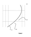
- Figure 6 illustrates centroids determined to correspond to deviations and not to correspond to deviations.
- First and second pluralities of centroids 610, 620 are identified to correspond to a change from the map data whereas a third plurality of centroids 630 (and others not specifically indicated in Figure 6 ) are identified not to correspond to changes from the map data.
- embodiments of the present invention assist in detecting deviations of map data and the real world represented by the map data.
- embodiments of the present invention can be realised in the form of hardware, software or a combination of hardware and software. Any such software may be stored in the form of volatile or non-volatile storage such as, for example, a storage device like a ROM, whether erasable or rewritable or not, or in the form of memory such as, for example, RAM, memory chips, device or integrated circuits or on an optically or magnetically readable medium such as, for example, a CD, DVD, magnetic disk or magnetic tape. It will be appreciated that the storage devices and storage media are embodiments of machine-readable storage that are suitable for storing a program or programs that, when executed, implement embodiments of the present invention.
- embodiments provide a program comprising code for implementing a system or method as claimed in any preceding claim and a machine readable storage storing such a program. Still further, embodiments of the present invention may be conveyed electronically via any medium such as a communication signal carried over a wired or wireless connection and embodiments suitably encompass the same.
Landscapes
- Engineering & Computer Science (AREA)
- Radar, Positioning & Navigation (AREA)
- Remote Sensing (AREA)
- Automation & Control Theory (AREA)
- Physics & Mathematics (AREA)
- General Physics & Mathematics (AREA)
- Traffic Control Systems (AREA)
- Navigation (AREA)
- Instructional Devices (AREA)
- Information Retrieval, Db Structures And Fs Structures Therefor (AREA)
- Processing Or Creating Images (AREA)
Abstract
Description
- This invention relates to methods of identifying locations at which discrepancies or deviations exist between real world features and digital map data intended to represent those features. The real world features include navigable features (features traversable by a vehicle) such as road segments. Embodiments of the invention aim to automate a process of detecting and identifying such discrepancies to reduce a required intervention of an operator.
- Electronic map data is used in a wide variety of applications. One particular application is routing, such as in navigation devices. The accuracy of the routing is consequently dependent upon the accuracy of the map data. However, real world features, such as the layout of road networks which the map data is intended to represent, continually change and it is therefore required to keep the map data up-to-date. The map data for a country such as the Netherlands or the United Kingdom is large in size and map data for the US is enormous. Attempting to maintain the map data manually is an extremely difficult, or near impossible, task.
- Various technologies can be used to assist in maintaining map data. The technologies include satellite imagery and positional data relating to the movement of a plurality of devices with respect to time in an area. The devices may be carried by mapping vehicles intended to assist in maintaining or acquiring map data, or may be a vehicles carrying a navigation device.
- It is an object of embodiments of the invention to at least mitigate one or more of the problems of the prior art.
- According to a first aspect of the invention, therein is provided a method for identifying discrepancies in digital map data, comprising:
- selecting one or more candidate locations as a subset of locations within positional data relating to the movement of a plurality of devices with respect to time in an area;
- allocating each of the candidate locations to one or more predetermined categories based upon a distribution of travel directions of the devices at each candidate location; and
- comparing the candidate locations against a database of map data and identifying locations of possible discrepancies in the digital map data based upon the category of each candidate location.
- The method may further comprise determining the distribution of travel directions as a directional histogram. A rotation invariant histogram may be determined based upon the directional histogram. The step of allocating each of the candidate locations to one or more predetermined categories may be based upon the directional histogram or the invariant histogram, and in preferred embodiments is performed by a trained model.
- The method may further comprise determining an association between proximate candidate locations based upon the distribution of travel directions at each candidate location. The association may be determined, at least in part, based upon a metric indicative of a similarity between the distribution of travel directions for adjacent candidate locations. The comparing of the candidate locations against the database of map data may comprise comparing the category and association of each candidate location against the map data.
- The step of comparing the candidate locations against a database of map data may be performed by using a function F(L, {c 1...ck }, {L 1...Lk }), wherein the association of a candidate location c may be identified as {c 1...ck } having corresponding classifications of {L1...Lk } and an output of the function expresses a likelihood of a possible discrepancy in the digital map data at the candidate location. The function F may be a trained model.
- The candidate locations may be selected by determining locations of local maxima in the positional data.
- The method may further comprise a step of allocating the positional data to a pixel map corresponding to the area and determining, for at least pixels traversed by one or more devices, a value indicative of the number of devices traversing each pixel in the positional data. The candidate locations may be selected according to:

- According to a second aspect of the invention, there is provided a method of training a model to classify features in positional data, comprising:
- providing a training set comprising a plurality of distributions of travel directions of navigation devices, each distribution having an associated category identifier; and
- training a classification model to classify travel direction distributions based upon the training set.
- The category identifier may be indicative of each distribution of travel directions being one of a 1-way road, a 2-way road, a junction and clutter.
- The method may comprise evaluating the trained classification model using a test set comprising a plurality of travel distributions having unknown category identifiers.
- The method may comprise training a second classification model to identify possible discrepancies in digital map data based upon the category of each candidate location and an association of each candidate location with proximate candidate locations. The second classification model may provide a function F(L, {c 1...ck }, {L 1...Lk }), wherein the association of a candidate location c may be identified as {c1 ...ck } having corresponding classifications of {L1...Lk } and an output of the function F expresses a likelihood of a possible discrepancy in the digital map data at the candidate location. An output of the function F may be indicative of a likelihood of a discrepancy in the map data.
- The classification model or the second classification model may be one of a stochastic model, a decision tree classifiers, rule-based classifiers, neural networks, support vector machines.
- The method of the first aspect of the invention, in any of its embodiments, may comprise using the classification model generated in the second aspect of the invention to allocate each of the candidate locations to the one or more predetermined categories.
- Any of the methods described above may be implemented as software, and thus the invention extends to computer software which, when executed by a computer, is arranged to perform any of the described methods. The computer software may be stored on a, e.g. non-transitory, computer-readable medium.
- Embodiments of the invention will now be described by way of example only, with reference to the accompanying figures, in which:
-
Figure 1 is a flowchart illustrating a method for identifying discrepancies in digital map data according to an embodiment of the invention; -
Figure 2 illustrates an allocation of traces to a pixel map according to an embodiment of the invention; -
Figure 3 is a heat map illustrating the pixel map according to an embodiment of the invention; -
Figure 4 is a map of centroids according to an embodiment of the invention; -
Figure 5 is a map of classified centroids according to an embodiment of the invention; -
Figure 6 is an illustration of digital map data and centroids determined to correspond to discrepancies from the digital map data according to an embodiment of the invention; and -
Figure 7 is a flowchart illustrating a method of training a model to classify features in positional data according to an embodiment of the invention. - Embodiments of the invention aim to identify locations at which discrepancies or deviations exist between real world features and digital map data intended to represent those features. The real world features include navigable features (features traversable by a vehicle) such as road segments. Embodiments of the invention aim to automate a process of detecting and identifying such discrepancies to reduce a required intervention of an operator.
-
Figure 1 illustrates amethod 100 according to an embodiment of the invention. Themethod 100, when executed by a processor of a computing device, determines locations at which map data may differ from real world features which the map data is intended to represent. The method determines the locations based upon trace data comprising one or more traces from location-aware mobile devices. Each trace indicates a geographic position of each mobile device against time i.e. traces the path of the device. - A location-aware mobile device, herein referred to simply as a mobile device, is any device capable of determining its geographic location from wirelessly received signals. The received signals may include received GPS signals. The mobile device may be a navigation device such as a portable navigation device (PND), in-vehicle navigation device, mobile phone, portable computing device, vehicle tracking device, and the like. The following description will assume that the mobile device is a navigation device, although it will be realised that embodiments of the invention are not restricted in this respect.
- The navigation device is arranged to record a trace of a path or route followed by the navigation device. The navigation device may store the trace in a local memory of the navigation device or may communicate the trace to a server computer, such as via a wireless data connection with the server computer. The trace may be formed from data indicative of a series of geographic locations at which the navigation device is located at periodic intervals. However in other embodiments the trace may be formed by data representing one or more curves indicative of the path of the navigation device. The
method 100 may be used with trace data comprising one or more traces. In some embodiments of the invention themethod 100 is used with a bundle comprising a plurality of traces. The plurality of traces may be received from one or more navigation devices. The method may comprise a step (not shown) of receiving the one or more traces from one or more mobile devices, such as navigation devices. - In
step 110 the one or more traces are allocated to a pixel map.Figure 2 illustrates the allocation of atrace 210 to apixel map 200. The pixel map is a two-dimensional array comprising a plurality of pixels each representative of a geographic area. Each pixel may represent a geographic area of any shape, although in the embodiment shown inFigure 2 the pixel map comprises rectangular or square pixels. Rectangular pixels may be the most convenient shape to process by themethod 100 executed by the processor and to store in a memory. The geographic area represented by each pixel may be of any size. The size may be dependent upon an accuracy to which the navigation device providing the probe data may determine its location. The area may be 5 m by 5 m, 3.5 m by 3.5 m or 2 m by 2 m, although it will be realised that these are merely exemplary and, furthermore, in some embodiments the height and width of the area may not be equal. - Each pixel stores a value indicative of a number of times that pixel is crossed by a trace. When the pixel map is initialised each pixel is set to a predetermined value, such as 0. The pixel value is incremented each time the pixel is crossed by a trace. Referring to
Figure 2 , the value forpixels trace 210 crosses those pixels. It will be noted that even in cases where the trace is formed from a plurality of location values each indicative of the location of the navigation device at periodic intervals, should the trace comprise two or more location values within one pixel the value for that pixel is only incremented once to indicate the trace crossing the pixel, rather than once for each location within the pixel area. The pixel map values are incremented to reflect the number of times each of one or more traces crosses each pixel. Thus step 110 results in pixels which are crossed a greater number of times by traces storing a greater value. - It will be appreciated that, in the real world, most navigation devices will travel routes along roads in a road network. Occasionally, navigation devices will follow routes across other types of navigable location including private areas such as parking lots and the like. However the traces crossing these locations will be expected to be more random i.e. less constrained to following a particular path. Therefore pixels having a higher probability of corresponding to road locations will be expected to store greater
values following step 110. - Following step 110 a heat map may be displayed representative of the pixel map as shown in
Figure 3 . The heat map illustrates the values of the pixel map wherein brighter colours (those usually associated with higher temperatures) represent greater pixel values, i.e. more frequented locations. The axes ofFigure 3 indicate a distance in meters from an origin point at a bottom left corner ofFigure 3 . It can be appreciated fromFigure 3 that most traces follow roads which appear inFigure 3 in darker or similar "high temperature" colours whilst less traversed areas are indicated in lighter or similar "low temperature" colours. Based upon the pixel values it is possible to identify candidate locations having a relatively high probability of corresponding to navigable locations such as roadways, as will be described. - A direction map is also produced in
step 110. The direction map represents, for each pixel traversed by at least one trace, the direction in which the trace(s) traversed the pixel. - A directional histogram is stored for each pixel of the pixel map. In some embodiments a directional histogram may only be stored for each pixel which is traversed by at least one trace i.e. a directional histogram may only be initialised for a pixel once it is traversed by a trace and its corresponding pixel value incremented. In other embodiments a directional histogram may be initialised for each pixel of the pixel map.
- The directional histogram comprises a plurality of bins each representative of a direction of trace(s) across the corresponding pixel. Upon initialisation a value corresponding to each bin in the histogram is set to a predetermined value, such as 0. The value is incremented each time a trace traverses the corresponding pixel in that direction. In one embodiment the bins correspond to directions of 0° to 30°; 30° to 60°; ... 330° to 0°, although it will be realised that these angular divisions are merely exemplary and that other angular divisions may be envisaged.
- Thus for each pixel in the
pixel map 200 shown inFigure 2 a value indicates the number of times the pixel is traversed by a trace and, for at least the pixels traversed once by one or more traces, a directional histogram stores data indicative of the direction of the trace traversing the pixel. - In
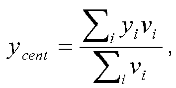
step 120 candidate locations in the probe data having a high probability of corresponding to navigable features such as roadways are identified. In one embodiment, the candidate locations are identified by determining pixels corresponding to local maxima of traversal frequency in the trace data. In other words, pixels are identified which are most crossed in the trace data. The coordinates (x cent, ycent ) of the local maxima in the pixel map may be determined as:
wherein xi , yi are the coordinates of the centre of mass of a pixel with a higher value than its adjacent pixels and vi is the value of the pixel. - The local maxima correspond to centroids which are pixel locations along roadway axles, or locations generally central along roads i.e. corresponding to a generally longitudinal axis of the road. Thus the centroids have a highest probability of corresponding to a spatial location of a road in the road network.
Figure 4 illustrates centroids identified from the pixel map illustrated inFigure 3 . - In
step 130 the centroids identified instep 120 are classified. That is, instep 130 the centroids are assigned to one or more of a plurality of classifications. The classifications indicate a type of navigable feature based upon the direction map produced instep 120. - In order to classify the centroids, firstly in in some embodiments of
step 130, the directional histograms are normalised. The directional histograms may be normalised such that a sum of values in all bins of each directional histogram is unity. - The directional histograms are transformed into rotation invariant representations. The rotation invariant histogram is obtained by circularly shifting bin values of each directional histogram. The bins values may be shifted such that a predetermined bin, such as the first bin, contains a greatest value. These steps may be explained with reference to a histogram h comprising 12 bins:
- h = [0, 0, 0, 93, 0, 0, 26, 0, 0, 5, 0, 32]
- Normalised histogram → h'= [0, 0, 0, 0.596, 0, 0, 0.167, 0, 0, 0.032, 0, 0.205]
- Rotation invariant histogram → h"= [0.596, 0, 0, 0.167, 0, 0, 0.032, 0, 0.205, 0, 0, 0]
- The conversion to the rotation invariant histogram allows a comparison between directional histograms to be made. By comparing the rotation invariant histograms they may be assigned to one of the plurality of categories. In some embodiments the histograms are classified by a stochastic model, such a Bayesian network which is trained to distinguish between histograms of the various categories. Other models may be useful such as decision tree classifiers, rule-based classifiers, neural networks, support vector machines and naive Bayes classifiers.
- The categories relate to a type of navigable area which each centroid represents. In some embodiments, the classifications correspond to 1-way (unidirectional), 2-way (bi-directional), junction and clutter. A 1-way histogram typically has a large value (close to 1) for the first bin in the rotation invariant representation, with other bin values substantially 0. A 2-way histogram typically has values around 0.5 for bins 1 and 7 (in a 12 bin histogram, otherwise approximately half-way i.e. opposite bin 1). A junction histogram has a pattern to the bin values. Typically the pattern comprises more than 2 substantially non-zero bin values. For example, a four way junction may be represented by a histogram having bin values of substantially 0.25 at 90° intervals, although other arrangements of junction can be envisaged having different intersection angles. In some embodiments more than one category may be provided for different types or angular arrangement of junctions. A clutter histogram represents an area having unstructured or undirected traffic flow, such as a car park and may have non-zero values in all bins, or substantially a majority of bins.
- Prior to being used to classify the histogram, such a model is trained using the
method 700 depicted in the flowchart ofFigure 7 . In the method, a training set having a plurality of histograms is obtained (step 710), each histogram having an associated category. Thus a learning algorithm may train the model to associate an input histogram with the appropriate classification based upon the training set (step 720). The associated category is indicative of the histogram being representative of, for example, a 1-way road, a 2-way road, a junction and a clutter location. When trained, the performance of the model may be verified by using a verification set of histograms without associated categories being provided to the model, although the category of each histogram is known for comparison against the category assigned by the model. The model may be re-trained, if necessary, or to introduce additional categories i.e. representative of new junction layouts etc. -
Figure 5 illustrates classified centroids representing an area in the city of Flanders. The centroids marked 510 represent exemplary 1-way centroids 510. The centroids marked 520 represent exemplary 2-way centroids. The centroid marked 530 is an example of an intersection centroid. The centroid marked 540 is an example of a clutter centroid. - In
step 140 centroids are connected to adjacent or spatially close centroids based upon one or more characteristics. The characteristics in one embodiment comprise the directional histograms associated with each centroid. Centroids having similar characteristics are connected instep 140. The similarity of centroids may be expressed by a metric. The metric may into account the fact that adjacent bins in the directional histograms are more indicative of similarity than distant bins. For example, that bins such as bin 11 and bin 0 (in a 12 bin histogram) are neighbouring bins, whereasbin 0 and bin 6 are opposite. Therefore the metric indicates the angular proximity of bins and similarity between directional histograms. Such a metric is used in the area of written text (character) recognition and has been applied by the present inventor to comparison of rotational histograms in the area of road network analysis. Further details are available in the publication Distance between histograms of angular measurements and its application to handwritten character similarity, Sung-Hyuk Cha; Srihari, S. N.; 2000 (ISBN: 0-7695-0750-6). - In
step 150 the centroids are compared against digital map data representative of an area for which the trace data was obtained. The map data indicates, amongst other things, the road network in the area. As a result of the comparison any discrepancies or deviations between the map data and the real world may be identified instep 160. - Step 150 comprises, in some embodiments, a first part in which centroids are identified which do not correspond to a location of a road in the map data. In some embodiments, the digital map data is scaled to match a scale of the pixel map in order to enable a comparison between the centroids and the map data. A location of each centroid is then compared against the map data to determine if a road exists at that geographic location. If no road exists at that location, or at a location within a predetermined distance of the centroid, then the centroid is marked or flagged for further analysis. If there is a road at the geographic location of the centroid then the centroid may be discarded, i.e. eliminated from further analysis. In other embodiments, all centroids are marked for further analysis, i.e. including those which correspond to the location of roads in the map data. This allows centroids corresponding to roads in the map data to be further analysed to detect changed road properties, such as a road having changed from 1-way to 2-way.
- Marked or flagged centroids are analysed to determine whether they relate to a deviation from the map data i.e. a location at which the map data is potentially incorrect. In the second part of
step 160 the marked centroids are analysed to determine with a greater degree of confidence whether they correspond to such a deviation. - In embodiments of the invention, a marked centroid is determined to correspond to a deviation from the map data based upon its classification and connections.
- As explained above, centroids may be classified and the classification of a marked centroid c may be indicated as L. In some embodiments, as noted above, the classifications L may be 1-way, 2-way, intersection or clutter, although it will be realised that these are merely exemplary. The connections of the marked centroid c may be identified as {c1 ...ck } with corresponding classifications of {L1...Lk }.
- A function F may be arranged to output true or false to indicate whether the marked centroid c corresponds to a change from the map data based upon the classification of the marked centroid and its connections as:

- For example, a marked centroid having no connections or being connected to only clutter centroids may be rejected. That is, the marked centroid may be determined not to represent a deviation or real-world change from the map data. This determination may be made on the basis that the classification and connections of the marked centroid do not indicate with significant reliability that the real world road network has changed from the map data. However, a marked centroid having a predetermined classification connected to a plurality of centroids of the same classification, e.g. a centroid classified as 1-way connected to four other similarly classified centroids, may be identified as a real-world change. As such the function F outputs true to indicate the determination of the marked centroid as a deviation from the map data. The function may be a heuristic function or be a trained model.
-
Figure 6 illustrates centroids determined to correspond to deviations and not to correspond to deviations. First and second pluralities ofcentroids Figure 6 ) are identified not to correspond to changes from the map data. - It will be appreciated that embodiments of the present invention assist in detecting deviations of map data and the real world represented by the map data.
- It will be appreciated that embodiments of the present invention can be realised in the form of hardware, software or a combination of hardware and software. Any such software may be stored in the form of volatile or non-volatile storage such as, for example, a storage device like a ROM, whether erasable or rewritable or not, or in the form of memory such as, for example, RAM, memory chips, device or integrated circuits or on an optically or magnetically readable medium such as, for example, a CD, DVD, magnetic disk or magnetic tape. It will be appreciated that the storage devices and storage media are embodiments of machine-readable storage that are suitable for storing a program or programs that, when executed, implement embodiments of the present invention. Accordingly, embodiments provide a program comprising code for implementing a system or method as claimed in any preceding claim and a machine readable storage storing such a program. Still further, embodiments of the present invention may be conveyed electronically via any medium such as a communication signal carried over a wired or wireless connection and embodiments suitably encompass the same.
- All of the features disclosed in this specification (including any accompanying claims, abstract and drawings), and/or all of the steps of any method or process so disclosed, may be combined in any combination, except combinations where at least some of such features and/or steps are mutually exclusive.
- Each feature disclosed in this specification (including any accompanying claims, abstract and drawings), may be replaced by alternative features serving the same, equivalent or similar purpose, unless expressly stated otherwise. Thus, unless expressly stated otherwise, each feature disclosed is one example only of a generic series of equivalent or similar features.
- The invention is not restricted to the details of any foregoing embodiments. The invention extends to any novel one, or any novel combination, of the features disclosed in this specification (including any accompanying claims, abstract and drawings), or to any novel one, or any novel combination, of the steps of any method or process so disclosed. The claims should not be construed to cover merely the foregoing embodiments, but also any embodiments which fall within the scope of the claims.
Claims (15)
- A method for identifying discrepancies in digital map data, comprising:selecting one or more candidate locations as a subset of locations within positional data relating to the movement of a plurality of devices with respect to time in an area (110,120);allocating each of the candidate locations to one or more predetermined categories based upon a distribution of travel directions of the devices at each candidate location (130); andcomparing the candidate locations against a database of map data and identifying locations of possible discrepancies in the digital map data based upon the category of each candidate location (150,160).
- The method of claim 1, comprising determining the distribution of travel directions as a directional histogram, and wherein the allocating (130) is based upon the directional histogram.
- The method of claim 2, comprising determining a rotation invariant histogram based upon the directional histogram, and wherein the allocating (130) is based upon the rotation invariant histogram.
- The method of any preceding claim, wherein the allocating (130) is performed by a trained model.
- The method of any preceding claim, comprising determining an association between proximate candidate locations based upon the distribution of travel directions at each candidate location.
- The method of claim 5, wherein the association is determined, at least in part, based upon a metric indicative of a similarity between the distribution of travel directions for adjacent candidate locations.
- The method of claim 5 or 6, wherein the comparing of the candidate locations against the database of map data (150) comprises comparing the category and association of each candidate location against the map data.
- The method of any preceding claim, wherein the comparing (150) results in a likelihood of a possible discrepancy in the digital map data at the candidate location.
- The method of any preceding claim, wherein the candidate locations are selected by determining locations of local maxima in the positional data.
- The method of any preceding claim, comprising a step of allocating the positional data to a pixel map corresponding to the area (110) and determining, for at least pixels traversed by one or more devices, a value indicative of the number of devices traversing each pixel in the positional data (120).
- A method of training a model to classify features in positional data, comprising:providing a training set comprising a plurality of distributions of travel directions of navigation devices, each distribution having an associated category identifier (710); andtraining a classification model to classify travel direction distributions based upon the training set (720).
- The method of claim 11, wherein the category identifier is indicative of each distribution of travel directions being one of a 1-way road, a 2-way road, a junction and clutter.
- The method of claim 11 or 12, comprising training a second classification model to identify possible discrepancies in digital map data based upon the category of each candidate location and an association of each candidate location with proximate candidate locations.
- The method of claims 11 to 13, comprising using the classification model in the method of any of claims 1 to 10 to allocate each of the candidate locations to the one or more predetermined categories.
- Computer software which, when executed by a computer, is arranged to perform the method of any preceding claim, optionally stored on a non-transitory computer-readable medium.
Applications Claiming Priority (1)
| Application Number | Priority Date | Filing Date | Title |
|---|---|---|---|
| GBGB1211636.4A GB201211636D0 (en) | 2012-06-29 | 2012-06-29 | Method and apparatus for detecting deviations from map data |
Publications (3)
| Publication Number | Publication Date |
|---|---|
| EP2679956A2 true EP2679956A2 (en) | 2014-01-01 |
| EP2679956A3 EP2679956A3 (en) | 2014-05-14 |
| EP2679956B1 EP2679956B1 (en) | 2023-08-02 |
Family
ID=46721682
Family Applications (1)
| Application Number | Title | Priority Date | Filing Date |
|---|---|---|---|
| EP13174510.1A Active EP2679956B1 (en) | 2012-06-29 | 2013-07-01 | Method and Apparatus for Detecting Deviations from Map Data |
Country Status (3)
| Country | Link |
|---|---|
| US (2) | US11828601B2 (en) |
| EP (1) | EP2679956B1 (en) |
| GB (1) | GB201211636D0 (en) |
Cited By (10)
| Publication number | Priority date | Publication date | Assignee | Title |
|---|---|---|---|---|
| CN110914888A (en) * | 2017-11-22 | 2020-03-24 | 咪酷维亚科技有限公司 | Map information processing device, map information processing method, and map information processing program |
| EP3919860A1 (en) * | 2020-05-19 | 2021-12-08 | GEOTAB Inc. | Intelligent telematics system for defining road networks |
| US11335191B2 (en) | 2019-04-04 | 2022-05-17 | Geotab Inc. | Intelligent telematics system for defining road networks |
| US11335189B2 (en) | 2019-04-04 | 2022-05-17 | Geotab Inc. | Method for defining road networks |
| US11341846B2 (en) | 2019-04-04 | 2022-05-24 | Geotab Inc. | Traffic analytics system for defining road networks |
| US11403938B2 (en) | 2019-04-04 | 2022-08-02 | Geotab Inc. | Method for determining traffic metrics of a road network |
| US11410547B2 (en) | 2019-04-04 | 2022-08-09 | Geotab Inc. | Method for defining vehicle ways using machine learning |
| WO2024002589A1 (en) * | 2022-06-28 | 2024-01-04 | Mercedes-Benz Group AG | Method for determining and providing lane courses |
| EP4538642A1 (en) | 2023-10-12 | 2025-04-16 | TomTom Global Content B.V. | Systems and methods for correcting maps |
| WO2025078041A1 (en) | 2023-10-12 | 2025-04-17 | Tomtom Global Content B.V. | Systems and methods for updating road geometry graphs |
Families Citing this family (5)
| Publication number | Priority date | Publication date | Assignee | Title |
|---|---|---|---|---|
| EP3358303B1 (en) * | 2017-02-07 | 2021-09-01 | HERE Global B.V. | An apparatus and associated methods for use in updating map data |
| DE102017216237A1 (en) * | 2017-09-14 | 2019-03-14 | Bayerische Motoren Werke Aktiengesellschaft | Method for determining a course of lanes of a road network and server device for carrying out the method |
| CN111279386B (en) * | 2017-11-03 | 2023-03-24 | 北京嘀嘀无限科技发展有限公司 | System and method for new road determination |
| EP3922947A3 (en) * | 2020-05-19 | 2022-02-09 | GEOTAB Inc. | Traffic analytics system for defining road networks |
| US20250237767A1 (en) * | 2024-01-19 | 2025-07-24 | Ford Global Technologies, Llc | Gnss deviation map layer |
Family Cites Families (13)
| Publication number | Priority date | Publication date | Assignee | Title |
|---|---|---|---|---|
| US6047234A (en) | 1997-10-16 | 2000-04-04 | Navigation Technologies Corporation | System and method for updating, enhancing or refining a geographic database using feedback |
| US6385539B1 (en) * | 1999-08-13 | 2002-05-07 | Daimlerchrysler Ag | Method and system for autonomously developing or augmenting geographical databases by mining uncoordinated probe data |
| JP4654823B2 (en) * | 2005-08-03 | 2011-03-23 | 株式会社デンソー | Road map data update system and road detection system |
| US8184159B2 (en) * | 2007-03-26 | 2012-05-22 | Trw Automotive U.S. Llc | Forward looking sensor system |
| RU2010123016A (en) | 2007-11-06 | 2011-12-20 | Теле Атлас Норт Америка Инк. (Us) | METHOD AND SYSTEM FOR USING MEASUREMENT DATA FROM MANY VEHICLES FOR DETECTING REAL-WORLD CHANGES FOR USE WHEN MAP UPDATES |
| US20100256903A1 (en) * | 2009-04-01 | 2010-10-07 | General Motors Corporation | Vehicle telematics communication for generating road routing informatiion |
| WO2011023244A1 (en) | 2009-08-25 | 2011-03-03 | Tele Atlas B.V. | Method and system of processing data gathered using a range sensor |
| JP2013529291A (en) * | 2010-04-09 | 2013-07-18 | トムトム ノース アメリカ インコーポレイテッド | How to resolve the location from the data representing the location |
| US9696166B2 (en) * | 2010-10-06 | 2017-07-04 | Google Inc. | Automated identification of anomalous map data |
| US8379994B2 (en) * | 2010-10-13 | 2013-02-19 | Sony Corporation | Digital image analysis utilizing multiple human labels |
| US8718380B2 (en) * | 2011-02-14 | 2014-05-06 | Mitsubishi Electric Research Laboratories, Inc. | Representing object shapes using radial basis function support vector machine classification |
| US8554473B2 (en) * | 2011-04-25 | 2013-10-08 | Navteq B.V. | Energy efficient routing using an impedance factor |
| US10070708B2 (en) * | 2012-05-07 | 2018-09-11 | Jordan Creativeworks, Llc | Combination beverage and storage container with movable closure |
-
2012
- 2012-06-29 GB GBGB1211636.4A patent/GB201211636D0/en not_active Ceased
-
2013
- 2013-07-01 US US13/932,067 patent/US11828601B2/en active Active
- 2013-07-01 EP EP13174510.1A patent/EP2679956B1/en active Active
-
2023
- 2023-11-17 US US18/513,362 patent/US12209868B2/en active Active
Cited By (19)
| Publication number | Priority date | Publication date | Assignee | Title |
|---|---|---|---|---|
| CN110914888A (en) * | 2017-11-22 | 2020-03-24 | 咪酷维亚科技有限公司 | Map information processing device, map information processing method, and map information processing program |
| EP3614366A4 (en) * | 2017-11-22 | 2020-12-23 | Micware Co., Ltd. | CARD INFORMATION PROCESSING DEVICE, CARD INFORMATION PROCESSING METHOD, AND CARD INFORMATION PROGRAM |
| US11423773B2 (en) | 2019-04-04 | 2022-08-23 | Geotab Inc. | Traffic analytics system for defining vehicle ways |
| US11699100B2 (en) | 2019-04-04 | 2023-07-11 | Geotab Inc. | System for determining traffic metrics of a road network |
| US11335189B2 (en) | 2019-04-04 | 2022-05-17 | Geotab Inc. | Method for defining road networks |
| US11341846B2 (en) | 2019-04-04 | 2022-05-24 | Geotab Inc. | Traffic analytics system for defining road networks |
| US11403938B2 (en) | 2019-04-04 | 2022-08-02 | Geotab Inc. | Method for determining traffic metrics of a road network |
| US11410547B2 (en) | 2019-04-04 | 2022-08-09 | Geotab Inc. | Method for defining vehicle ways using machine learning |
| US11710074B2 (en) | 2019-04-04 | 2023-07-25 | Geotab Inc. | System for providing corridor metrics for a corridor of a road network |
| US11443617B2 (en) | 2019-04-04 | 2022-09-13 | Geotab Inc. | Method for defining intersections using machine learning |
| US11450202B2 (en) | 2019-04-04 | 2022-09-20 | Geotab Inc. | Method and system for determining a geographical area occupied by an intersection |
| US11335191B2 (en) | 2019-04-04 | 2022-05-17 | Geotab Inc. | Intelligent telematics system for defining road networks |
| US11710073B2 (en) | 2019-04-04 | 2023-07-25 | Geo tab Inc. | Method for providing corridor metrics for a corridor of a road network |
| EP3919860A1 (en) * | 2020-05-19 | 2021-12-08 | GEOTAB Inc. | Intelligent telematics system for defining road networks |
| WO2024002589A1 (en) * | 2022-06-28 | 2024-01-04 | Mercedes-Benz Group AG | Method for determining and providing lane courses |
| JP2025521673A (en) * | 2022-06-28 | 2025-07-10 | メルセデス・ベンツ グループ アクチェンゲゼルシャフト | Method for calculating and providing lane routes |
| JP7714821B2 (en) | 2022-06-28 | 2025-07-29 | メルセデス・ベンツ グループ アクチェンゲゼルシャフト | Method for calculating and providing lane routes |
| EP4538642A1 (en) | 2023-10-12 | 2025-04-16 | TomTom Global Content B.V. | Systems and methods for correcting maps |
| WO2025078041A1 (en) | 2023-10-12 | 2025-04-17 | Tomtom Global Content B.V. | Systems and methods for updating road geometry graphs |
Also Published As
| Publication number | Publication date |
|---|---|
| US20240159543A1 (en) | 2024-05-16 |
| US20140074847A1 (en) | 2014-03-13 |
| US12209868B2 (en) | 2025-01-28 |
| EP2679956A3 (en) | 2014-05-14 |
| EP2679956B1 (en) | 2023-08-02 |
| US11828601B2 (en) | 2023-11-28 |
| GB201211636D0 (en) | 2012-08-15 |
Similar Documents
| Publication | Publication Date | Title |
|---|---|---|
| US12209868B2 (en) | Method and apparatus for detecting deviations from map data | |
| US11118921B2 (en) | Vehicle routing guidance to an authoritative location for a point of interest | |
| EP3673407B1 (en) | Automatic occlusion detection in road network data | |
| Lloyd | Spatial data analysis: an introduction for GIS users | |
| Yang et al. | Urban freight delivery stop identification with GPS data | |
| US6732046B1 (en) | Application of the hough transform to modeling the horizontal component of road geometry and computing heading and curvature | |
| Sharma et al. | Deep learning-based object detection and classification for autonomous vehicles in different weather scenarios of Quebec, Canada | |
| Samardžić‐Petrović et al. | Modeling urban land use changes using support vector machines | |
| CN113950611B (en) | Method and data processing system for predicting road properties | |
| Ai et al. | Automatic horizontal curve identification and measurement method using GPS data | |
| US11663499B2 (en) | Method, data processing apparatus and computer program product for determining road intersections | |
| WO2014062118A1 (en) | System and method in connection with occurrence of platoons | |
| CN116071722B (en) | Lane geometric information extraction method, system, equipment and medium based on road section track | |
| JP6716480B2 (en) | Road network change detecting device, road network change detecting method, computer program, and recording medium recording computer program | |
| US20240262385A1 (en) | Spatio-temporal pose/object database | |
| KR102286178B1 (en) | System for evaluating HD map quality and distributing index | |
| CN114705203B (en) | Data processing method and computing device | |
| Lee et al. | Object Detection of Road Facilities Using YOLOv3 for High-definition Map Updates. | |
| KR102288623B1 (en) | Map Data Processing and Format Change Method for Land Vehicle Simulation | |
| US20210270629A1 (en) | Method and apparatus for selecting a path to a destination | |
| Jeong et al. | A Framework for Remote Road Furniture Monitoring System Using Smart IoT Dashcams and Digital Twin | |
| Kim et al. | A study on travel time estimation of diverging traffic stream on highways based on timestamp data | |
| CN116933086A (en) | Training method of road boundary detection model, road boundary detection method and device | |
| Roth et al. | CrowdAbout: Using vehicles as sensors to improve map data for ITS | |
| CN116481567A (en) | Method and system for evaluating the accuracy of high-precision maps |
Legal Events
| Date | Code | Title | Description |
|---|---|---|---|
| PUAI | Public reference made under article 153(3) epc to a published international application that has entered the european phase |
Free format text: ORIGINAL CODE: 0009012 |
|
| AK | Designated contracting states |
Kind code of ref document: A2 Designated state(s): AL AT BE BG CH CY CZ DE DK EE ES FI FR GB GR HR HU IE IS IT LI LT LU LV MC MK MT NL NO PL PT RO RS SE SI SK SM TR |
|
| AX | Request for extension of the european patent |
Extension state: BA ME |
|
| PUAL | Search report despatched |
Free format text: ORIGINAL CODE: 0009013 |
|
| AK | Designated contracting states |
Kind code of ref document: A3 Designated state(s): AL AT BE BG CH CY CZ DE DK EE ES FI FR GB GR HR HU IE IS IT LI LT LU LV MC MK MT NL NO PL PT RO RS SE SI SK SM TR |
|
| AX | Request for extension of the european patent |
Extension state: BA ME |
|
| RIC1 | Information provided on ipc code assigned before grant |
Ipc: G01C 21/32 20060101AFI20140409BHEP |
|
| 17P | Request for examination filed |
Effective date: 20141114 |
|
| RBV | Designated contracting states (corrected) |
Designated state(s): AL AT BE BG CH CY CZ DE DK EE ES FI FR GB GR HR HU IE IS IT LI LT LU LV MC MK MT NL NO PL PT RO RS SE SI SK SM TR |
|
| STAA | Information on the status of an ep patent application or granted ep patent |
Free format text: STATUS: EXAMINATION IS IN PROGRESS |
|
| 17Q | First examination report despatched |
Effective date: 20170612 |
|
| RAP1 | Party data changed (applicant data changed or rights of an application transferred) |
Owner name: TOMTOM GLOBAL CONTENT B.V. |
|
| GRAP | Despatch of communication of intention to grant a patent |
Free format text: ORIGINAL CODE: EPIDOSNIGR1 |
|
| STAA | Information on the status of an ep patent application or granted ep patent |
Free format text: STATUS: GRANT OF PATENT IS INTENDED |
|
| INTG | Intention to grant announced |
Effective date: 20230224 |
|
| GRAS | Grant fee paid |
Free format text: ORIGINAL CODE: EPIDOSNIGR3 |
|
| P01 | Opt-out of the competence of the unified patent court (upc) registered |
Effective date: 20230520 |
|
| GRAA | (expected) grant |
Free format text: ORIGINAL CODE: 0009210 |
|
| STAA | Information on the status of an ep patent application or granted ep patent |
Free format text: STATUS: THE PATENT HAS BEEN GRANTED |
|
| AK | Designated contracting states |
Kind code of ref document: B1 Designated state(s): AL AT BE BG CH CY CZ DE DK EE ES FI FR GB GR HR HU IE IS IT LI LT LU LV MC MK MT NL NO PL PT RO RS SE SI SK SM TR |
|
| REG | Reference to a national code |
Ref country code: GB Ref legal event code: FG4D |
|
| REG | Reference to a national code |
Ref country code: CH Ref legal event code: EP |
|
| REG | Reference to a national code |
Ref country code: DE Ref legal event code: R096 Ref document number: 602013084353 Country of ref document: DE |
|
| REG | Reference to a national code |
Ref country code: IE Ref legal event code: FG4D |
|
| REG | Reference to a national code |
Ref country code: NL Ref legal event code: FP |
|
| REG | Reference to a national code |
Ref country code: LT Ref legal event code: MG9D |
|
| REG | Reference to a national code |
Ref country code: AT Ref legal event code: MK05 Ref document number: 1595257 Country of ref document: AT Kind code of ref document: T Effective date: 20230802 |
|
| PG25 | Lapsed in a contracting state [announced via postgrant information from national office to epo] |
Ref country code: GR Free format text: LAPSE BECAUSE OF FAILURE TO SUBMIT A TRANSLATION OF THE DESCRIPTION OR TO PAY THE FEE WITHIN THE PRESCRIBED TIME-LIMIT Effective date: 20231103 |
|
| PG25 | Lapsed in a contracting state [announced via postgrant information from national office to epo] |
Ref country code: IS Free format text: LAPSE BECAUSE OF FAILURE TO SUBMIT A TRANSLATION OF THE DESCRIPTION OR TO PAY THE FEE WITHIN THE PRESCRIBED TIME-LIMIT Effective date: 20231202 |
|
| PG25 | Lapsed in a contracting state [announced via postgrant information from national office to epo] |
Ref country code: SE Free format text: LAPSE BECAUSE OF FAILURE TO SUBMIT A TRANSLATION OF THE DESCRIPTION OR TO PAY THE FEE WITHIN THE PRESCRIBED TIME-LIMIT Effective date: 20230802 Ref country code: RS Free format text: LAPSE BECAUSE OF FAILURE TO SUBMIT A TRANSLATION OF THE DESCRIPTION OR TO PAY THE FEE WITHIN THE PRESCRIBED TIME-LIMIT Effective date: 20230802 Ref country code: PT Free format text: LAPSE BECAUSE OF FAILURE TO SUBMIT A TRANSLATION OF THE DESCRIPTION OR TO PAY THE FEE WITHIN THE PRESCRIBED TIME-LIMIT Effective date: 20231204 Ref country code: NO Free format text: LAPSE BECAUSE OF FAILURE TO SUBMIT A TRANSLATION OF THE DESCRIPTION OR TO PAY THE FEE WITHIN THE PRESCRIBED TIME-LIMIT Effective date: 20231102 Ref country code: LV Free format text: LAPSE BECAUSE OF FAILURE TO SUBMIT A TRANSLATION OF THE DESCRIPTION OR TO PAY THE FEE WITHIN THE PRESCRIBED TIME-LIMIT Effective date: 20230802 Ref country code: LT Free format text: LAPSE BECAUSE OF FAILURE TO SUBMIT A TRANSLATION OF THE DESCRIPTION OR TO PAY THE FEE WITHIN THE PRESCRIBED TIME-LIMIT Effective date: 20230802 Ref country code: IS Free format text: LAPSE BECAUSE OF FAILURE TO SUBMIT A TRANSLATION OF THE DESCRIPTION OR TO PAY THE FEE WITHIN THE PRESCRIBED TIME-LIMIT Effective date: 20231202 Ref country code: HR Free format text: LAPSE BECAUSE OF FAILURE TO SUBMIT A TRANSLATION OF THE DESCRIPTION OR TO PAY THE FEE WITHIN THE PRESCRIBED TIME-LIMIT Effective date: 20230802 Ref country code: GR Free format text: LAPSE BECAUSE OF FAILURE TO SUBMIT A TRANSLATION OF THE DESCRIPTION OR TO PAY THE FEE WITHIN THE PRESCRIBED TIME-LIMIT Effective date: 20231103 Ref country code: FI Free format text: LAPSE BECAUSE OF FAILURE TO SUBMIT A TRANSLATION OF THE DESCRIPTION OR TO PAY THE FEE WITHIN THE PRESCRIBED TIME-LIMIT Effective date: 20230802 Ref country code: AT Free format text: LAPSE BECAUSE OF FAILURE TO SUBMIT A TRANSLATION OF THE DESCRIPTION OR TO PAY THE FEE WITHIN THE PRESCRIBED TIME-LIMIT Effective date: 20230802 |
|
| PG25 | Lapsed in a contracting state [announced via postgrant information from national office to epo] |
Ref country code: PL Free format text: LAPSE BECAUSE OF FAILURE TO SUBMIT A TRANSLATION OF THE DESCRIPTION OR TO PAY THE FEE WITHIN THE PRESCRIBED TIME-LIMIT Effective date: 20230802 |
|
| PG25 | Lapsed in a contracting state [announced via postgrant information from national office to epo] |
Ref country code: ES Free format text: LAPSE BECAUSE OF FAILURE TO SUBMIT A TRANSLATION OF THE DESCRIPTION OR TO PAY THE FEE WITHIN THE PRESCRIBED TIME-LIMIT Effective date: 20230802 |
|
| PG25 | Lapsed in a contracting state [announced via postgrant information from national office to epo] |
Ref country code: SM Free format text: LAPSE BECAUSE OF FAILURE TO SUBMIT A TRANSLATION OF THE DESCRIPTION OR TO PAY THE FEE WITHIN THE PRESCRIBED TIME-LIMIT Effective date: 20230802 Ref country code: RO Free format text: LAPSE BECAUSE OF FAILURE TO SUBMIT A TRANSLATION OF THE DESCRIPTION OR TO PAY THE FEE WITHIN THE PRESCRIBED TIME-LIMIT Effective date: 20230802 Ref country code: ES Free format text: LAPSE BECAUSE OF FAILURE TO SUBMIT A TRANSLATION OF THE DESCRIPTION OR TO PAY THE FEE WITHIN THE PRESCRIBED TIME-LIMIT Effective date: 20230802 Ref country code: EE Free format text: LAPSE BECAUSE OF FAILURE TO SUBMIT A TRANSLATION OF THE DESCRIPTION OR TO PAY THE FEE WITHIN THE PRESCRIBED TIME-LIMIT Effective date: 20230802 Ref country code: DK Free format text: LAPSE BECAUSE OF FAILURE TO SUBMIT A TRANSLATION OF THE DESCRIPTION OR TO PAY THE FEE WITHIN THE PRESCRIBED TIME-LIMIT Effective date: 20230802 Ref country code: CZ Free format text: LAPSE BECAUSE OF FAILURE TO SUBMIT A TRANSLATION OF THE DESCRIPTION OR TO PAY THE FEE WITHIN THE PRESCRIBED TIME-LIMIT Effective date: 20230802 Ref country code: SK Free format text: LAPSE BECAUSE OF FAILURE TO SUBMIT A TRANSLATION OF THE DESCRIPTION OR TO PAY THE FEE WITHIN THE PRESCRIBED TIME-LIMIT Effective date: 20230802 |
|
| REG | Reference to a national code |
Ref country code: DE Ref legal event code: R097 Ref document number: 602013084353 Country of ref document: DE |
|
| PG25 | Lapsed in a contracting state [announced via postgrant information from national office to epo] |
Ref country code: IT Free format text: LAPSE BECAUSE OF FAILURE TO SUBMIT A TRANSLATION OF THE DESCRIPTION OR TO PAY THE FEE WITHIN THE PRESCRIBED TIME-LIMIT Effective date: 20230802 |
|
| PLBE | No opposition filed within time limit |
Free format text: ORIGINAL CODE: 0009261 |
|
| STAA | Information on the status of an ep patent application or granted ep patent |
Free format text: STATUS: NO OPPOSITION FILED WITHIN TIME LIMIT |
|
| 26N | No opposition filed |
Effective date: 20240503 |
|
| PG25 | Lapsed in a contracting state [announced via postgrant information from national office to epo] |
Ref country code: SI Free format text: LAPSE BECAUSE OF FAILURE TO SUBMIT A TRANSLATION OF THE DESCRIPTION OR TO PAY THE FEE WITHIN THE PRESCRIBED TIME-LIMIT Effective date: 20230802 |
|
| PG25 | Lapsed in a contracting state [announced via postgrant information from national office to epo] |
Ref country code: BG Free format text: LAPSE BECAUSE OF FAILURE TO SUBMIT A TRANSLATION OF THE DESCRIPTION OR TO PAY THE FEE WITHIN THE PRESCRIBED TIME-LIMIT Effective date: 20230802 |
|
| PG25 | Lapsed in a contracting state [announced via postgrant information from national office to epo] |
Ref country code: BG Free format text: LAPSE BECAUSE OF FAILURE TO SUBMIT A TRANSLATION OF THE DESCRIPTION OR TO PAY THE FEE WITHIN THE PRESCRIBED TIME-LIMIT Effective date: 20230802 |
|
| PG25 | Lapsed in a contracting state [announced via postgrant information from national office to epo] |
Ref country code: MC Free format text: LAPSE BECAUSE OF FAILURE TO SUBMIT A TRANSLATION OF THE DESCRIPTION OR TO PAY THE FEE WITHIN THE PRESCRIBED TIME-LIMIT Effective date: 20230802 |
|
| REG | Reference to a national code |
Ref country code: CH Ref legal event code: PL |
|
| PG25 | Lapsed in a contracting state [announced via postgrant information from national office to epo] |
Ref country code: LU Free format text: LAPSE BECAUSE OF NON-PAYMENT OF DUE FEES Effective date: 20240701 |
|
| PG25 | Lapsed in a contracting state [announced via postgrant information from national office to epo] |
Ref country code: LU Free format text: LAPSE BECAUSE OF NON-PAYMENT OF DUE FEES Effective date: 20240701 |
|
| PG25 | Lapsed in a contracting state [announced via postgrant information from national office to epo] |
Ref country code: CH Free format text: LAPSE BECAUSE OF NON-PAYMENT OF DUE FEES Effective date: 20240731 Ref country code: BE Free format text: LAPSE BECAUSE OF NON-PAYMENT OF DUE FEES Effective date: 20240731 |
|
| REG | Reference to a national code |
Ref country code: BE Ref legal event code: MM Effective date: 20240731 |
|
| PGFP | Annual fee paid to national office [announced via postgrant information from national office to epo] |
Ref country code: GB Payment date: 20250605 Year of fee payment: 13 |
|
| PGFP | Annual fee paid to national office [announced via postgrant information from national office to epo] |
Ref country code: NL Payment date: 20250613 Year of fee payment: 13 |
|
| PGFP | Annual fee paid to national office [announced via postgrant information from national office to epo] |
Ref country code: FR Payment date: 20250610 Year of fee payment: 13 |
|
| PG25 | Lapsed in a contracting state [announced via postgrant information from national office to epo] |
Ref country code: IE Free format text: LAPSE BECAUSE OF NON-PAYMENT OF DUE FEES Effective date: 20240701 |
|
| PGFP | Annual fee paid to national office [announced via postgrant information from national office to epo] |
Ref country code: DE Payment date: 20250604 Year of fee payment: 13 |
|
| PG25 | Lapsed in a contracting state [announced via postgrant information from national office to epo] |
Ref country code: CY Free format text: LAPSE BECAUSE OF FAILURE TO SUBMIT A TRANSLATION OF THE DESCRIPTION OR TO PAY THE FEE WITHIN THE PRESCRIBED TIME-LIMIT; INVALID AB INITIO Effective date: 20130701 |
|
| PG25 | Lapsed in a contracting state [announced via postgrant information from national office to epo] |
Ref country code: HU Free format text: LAPSE BECAUSE OF FAILURE TO SUBMIT A TRANSLATION OF THE DESCRIPTION OR TO PAY THE FEE WITHIN THE PRESCRIBED TIME-LIMIT; INVALID AB INITIO Effective date: 20130701 |