EP2679772A1 - An airfoil - Google Patents
An airfoil Download PDFInfo
- Publication number
- EP2679772A1 EP2679772A1 EP13172933.7A EP13172933A EP2679772A1 EP 2679772 A1 EP2679772 A1 EP 2679772A1 EP 13172933 A EP13172933 A EP 13172933A EP 2679772 A1 EP2679772 A1 EP 2679772A1
- Authority
- EP
- European Patent Office
- Prior art keywords
- stagnation
- trench
- airfoil
- exterior surface
- pressure side
- Prior art date
- Legal status (The legal status is an assumption and is not a legal conclusion. Google has not performed a legal analysis and makes no representation as to the accuracy of the status listed.)
- Granted
Links
- 238000001816 cooling Methods 0.000 claims abstract description 66
- 239000012530 fluid Substances 0.000 claims abstract description 36
- 238000004891 communication Methods 0.000 claims abstract description 15
- 230000003247 decreasing effect Effects 0.000 claims description 6
- 239000000567 combustion gas Substances 0.000 description 9
- 238000002485 combustion reaction Methods 0.000 description 8
- 239000000446 fuel Substances 0.000 description 7
- 239000007789 gas Substances 0.000 description 6
- 230000007704 transition Effects 0.000 description 3
- ATUOYWHBWRKTHZ-UHFFFAOYSA-N Propane Chemical compound CCC ATUOYWHBWRKTHZ-UHFFFAOYSA-N 0.000 description 2
- 239000003570 air Substances 0.000 description 2
- 239000003949 liquefied natural gas Substances 0.000 description 2
- VNWKTOKETHGBQD-UHFFFAOYSA-N methane Chemical compound C VNWKTOKETHGBQD-UHFFFAOYSA-N 0.000 description 2
- 238000000034 method Methods 0.000 description 2
- 238000012986 modification Methods 0.000 description 2
- 230000004048 modification Effects 0.000 description 2
- 238000011144 upstream manufacturing Methods 0.000 description 2
- 229910000851 Alloy steel Inorganic materials 0.000 description 1
- 239000012080 ambient air Substances 0.000 description 1
- 230000004323 axial length Effects 0.000 description 1
- 229910010293 ceramic material Inorganic materials 0.000 description 1
- 239000000571 coke Substances 0.000 description 1
- 230000005611 electricity Effects 0.000 description 1
- 239000001257 hydrogen Substances 0.000 description 1
- 229910052739 hydrogen Inorganic materials 0.000 description 1
- 125000004435 hydrogen atom Chemical class [H]* 0.000 description 1
- 239000000203 mixture Substances 0.000 description 1
- 239000003345 natural gas Substances 0.000 description 1
- 230000037361 pathway Effects 0.000 description 1
- 238000010248 power generation Methods 0.000 description 1
- 230000008569 process Effects 0.000 description 1
- 239000001294 propane Substances 0.000 description 1
- -1 steam Substances 0.000 description 1
Images


Classifications
-
- F—MECHANICAL ENGINEERING; LIGHTING; HEATING; WEAPONS; BLASTING
- F01—MACHINES OR ENGINES IN GENERAL; ENGINE PLANTS IN GENERAL; STEAM ENGINES
- F01D—NON-POSITIVE DISPLACEMENT MACHINES OR ENGINES, e.g. STEAM TURBINES
- F01D5/00—Blades; Blade-carrying members; Heating, heat-insulating, cooling or antivibration means on the blades or the members
- F01D5/12—Blades
- F01D5/14—Form or construction
- F01D5/18—Hollow blades, i.e. blades with cooling or heating channels or cavities; Heating, heat-insulating or cooling means on blades
- F01D5/186—Film cooling
-
- F—MECHANICAL ENGINEERING; LIGHTING; HEATING; WEAPONS; BLASTING
- F01—MACHINES OR ENGINES IN GENERAL; ENGINE PLANTS IN GENERAL; STEAM ENGINES
- F01D—NON-POSITIVE DISPLACEMENT MACHINES OR ENGINES, e.g. STEAM TURBINES
- F01D5/00—Blades; Blade-carrying members; Heating, heat-insulating, cooling or antivibration means on the blades or the members
- F01D5/12—Blades
- F01D5/14—Form or construction
- F01D5/18—Hollow blades, i.e. blades with cooling or heating channels or cavities; Heating, heat-insulating or cooling means on blades
- F01D5/187—Convection cooling
-
- F—MECHANICAL ENGINEERING; LIGHTING; HEATING; WEAPONS; BLASTING
- F05—INDEXING SCHEMES RELATING TO ENGINES OR PUMPS IN VARIOUS SUBCLASSES OF CLASSES F01-F04
- F05D—INDEXING SCHEME FOR ASPECTS RELATING TO NON-POSITIVE-DISPLACEMENT MACHINES OR ENGINES, GAS-TURBINES OR JET-PROPULSION PLANTS
- F05D2240/00—Components
- F05D2240/20—Rotors
- F05D2240/30—Characteristics of rotor blades, i.e. of any element transforming dynamic fluid energy to or from rotational energy and being attached to a rotor
- F05D2240/305—Characteristics of rotor blades, i.e. of any element transforming dynamic fluid energy to or from rotational energy and being attached to a rotor related to the pressure side of a rotor blade
-
- F—MECHANICAL ENGINEERING; LIGHTING; HEATING; WEAPONS; BLASTING
- F05—INDEXING SCHEMES RELATING TO ENGINES OR PUMPS IN VARIOUS SUBCLASSES OF CLASSES F01-F04
- F05D—INDEXING SCHEME FOR ASPECTS RELATING TO NON-POSITIVE-DISPLACEMENT MACHINES OR ENGINES, GAS-TURBINES OR JET-PROPULSION PLANTS
- F05D2240/00—Components
- F05D2240/20—Rotors
- F05D2240/30—Characteristics of rotor blades, i.e. of any element transforming dynamic fluid energy to or from rotational energy and being attached to a rotor
- F05D2240/306—Characteristics of rotor blades, i.e. of any element transforming dynamic fluid energy to or from rotational energy and being attached to a rotor related to the suction side of a rotor blade
-
- F—MECHANICAL ENGINEERING; LIGHTING; HEATING; WEAPONS; BLASTING
- F05—INDEXING SCHEMES RELATING TO ENGINES OR PUMPS IN VARIOUS SUBCLASSES OF CLASSES F01-F04
- F05D—INDEXING SCHEME FOR ASPECTS RELATING TO NON-POSITIVE-DISPLACEMENT MACHINES OR ENGINES, GAS-TURBINES OR JET-PROPULSION PLANTS
- F05D2260/00—Function
- F05D2260/20—Heat transfer, e.g. cooling
- F05D2260/202—Heat transfer, e.g. cooling by film cooling
-
- F—MECHANICAL ENGINEERING; LIGHTING; HEATING; WEAPONS; BLASTING
- F05—INDEXING SCHEMES RELATING TO ENGINES OR PUMPS IN VARIOUS SUBCLASSES OF CLASSES F01-F04
- F05D—INDEXING SCHEME FOR ASPECTS RELATING TO NON-POSITIVE-DISPLACEMENT MACHINES OR ENGINES, GAS-TURBINES OR JET-PROPULSION PLANTS
- F05D2260/00—Function
- F05D2260/20—Heat transfer, e.g. cooling
- F05D2260/204—Heat transfer, e.g. cooling by the use of microcircuits
Definitions
- the present invention generally involves an airfoil, such as might be used in a turbine.
- Turbines are widely used in a variety of aviation, industrial, and power generation applications to perform work.
- Each turbine generally includes alternating stages of circumferentially mounted stator vanes and rotating blades.
- Each stator vane and rotating blade may include high alloy steel and/or ceramic material shaped into an airfoil.
- a compressed working fluid such as steam, combustion gases, or air, flows across the stator vanes and rotating blades along a gas path in the turbine.
- the stator vanes accelerate and direct the compressed working fluid onto the subsequent stage of rotating blades to impart motion to the rotating blades and perform work.
- a cooling media may be supplied inside the airfoils and released through the airfoils to provide film cooling to the outside of the airfoils. Trenches in the airfoils evenly distribute the cooling media across the external surface of the airfoils. However, an improved airfoil that varies the distribution of the cooling media across the external surface of the airfoils would be useful.
- One aspect of the present invention is an airfoil that includes an interior surface, an exterior surface opposed to the interior surface, a pressure side, a suction side opposed to the pressure side, a stagnation line between the pressure and suction sides, and a trailing edge between the pressure and suction sides and downstream from the stagnation line.
- a first column of overlapping stagnation trench segments is on the exterior surface, and the stagnation line passes through at least a portion of each of the overlapping stagnation trench segments. At least one cooling passage in each stagnation trench segment provides fluid communication from the interior surface to the exterior surface.
- Another aspect of the present invention is an airfoil that includes an interior surface, an exterior surface opposed to the interior surface, a pressure side, a suction side opposed to the pressure side, a stagnation line between the pressure and suction sides, and a trailing edge between the pressure and suction sides and downstream from the stagnation line.
- a second column of overlapping pressure side trench segments is on the pressure side
- a third column of overlapping suction side trench segments is on the suction side.
- Each pressure side trench segment and each suction side trench segment has a first end and a second end downstream and radially outward from the first end.
- At least one side cooling passage is in each pressure side trench segment and in each suction side trench segment, and the side cooling passages provide fluid communication from the interior surface to the exterior surface.
- an airfoil in yet another aspect, includes an interior surface, an exterior surface opposed to the interior surface, a pressure side, a suction side opposed to the pressure side, a stagnation line between the pressure and suction sides, and a trailing edge between the pressure and suction sides and downstream from the stagnation line.
- a first column of overlapping stagnation trench segments is on the exterior surface, and the stagnation line passes through at least a portion of each of the overlapping stagnation trench segments.
- At least one cooling passage is in each stagnation trench segment and provides fluid communication from the interior surface to the exterior surface.
- a second column of overlapping pressure side trench segments is on the pressure side, and a third column of overlapping suction side trench segments is on the suction side.
- At least one side cooling passage is in each pressure side trench segment and in each suction side trench segment to provide fluid communication from the interior surface to the exterior surface.
- Fig. 1 provides a perspective view of an airfoil 10 according to one embodiment of the present invention
- Fig. 2 provides a perspective view of the suction side of the airfoil shown in Fig. 1
- the airfoil 10 may be used, for example, as a rotating blade or stationary vane in a turbine to convert kinetic energy associated with a compressed working fluid into mechanical energy.
- the compressed working fluid may be steam, combustion gases, air, or any other fluid having kinetic energy.
- the airfoil 10 is generally connected to a platform or sidewall 12.
- the platform or sidewall 12 generally serves as the radial boundary for a gas path inside the turbine and provides an attachment point for the airfoil 10.
- the airfoil 10 may include an interior surface 16 and an exterior surface 18 opposed to the interior surface 16 and connected to the platform 12.
- the exterior surface generally includes a pressure side 20 and a suction side 22 opposed to the pressure side 20.
- the pressure side 20 is generally concave
- the suction side 22 is generally convex to provide an aerodynamic surface over which the compressed working fluid flows.
- a stagnation line 24 at a leading edge of the airfoil 10 between the pressure and suction sides 20, 22 represents the dividing line between fluid flow across the pressure side 20 and fluid flow across the suction side 22 of the airfoil 10.
- the stagnation line 24 often has the highest temperature over the exterior surface 18 of the airfoil 10.
- a trailing edge 26 is between the pressure and suction sides 20, 22 and downstream from the stagnation line 24. In this manner, the exterior surface 18 creates an aerodynamic surface suitable for converting the kinetic energy associated with the compressed working fluid into mechanical energy.
- the exterior surface 18 generally includes a radial length 30 that extends from the platform 12 radially outward and an axial length 32 that extends from the stagnation line 24 to the trailing edge 26.
- One or more columns of trench segments may extend radially and/or axially in the exterior surface 18, and each trench segment may include at least one cooling passage that provides fluid communication from the interior surface 16 to the exterior surface 18. In this manner, cooling media may be supplied inside the airfoil 10, and the cooling passages allow the cooling media to flow through the airfoil 10 to provide film cooling to the exterior surface 18.
- the trench segments may be located anywhere on the airfoil 10 and/or platform or sidewall 12, may be straight or arcuate, and may be aligned or staggered with respect to one another.
- the trench segments may have varying lengths, widths, and/or depths.
- the varying lengths, widths, and/or depths of the trench segments alter the distribution of the cooling media across the exterior surface 18. For example, widening the trench segments and making them shallower as they move away from the cooling passages may assist in diffusing the cooling media across the exterior surface 18.
- overlapping stagnation trench segments 40 may be arranged in a first column 42 on the exterior surface 18 so that the stagnation line 24 passes through at least a portion of each of the stagnation trench segments 40.
- Each stagnation trench segment 40 may be substantially straight and canted at an angle with respect to the immediately adjacent stagnation trench segment 40 so that the stagnation trench segments 40 overlap one another radially along the exterior surface 18.
- overlap means that moving radially outward from the platform 12, the end of one trench segment 40 is radially outward of the beginning of the next trench segment 40 in the same column.
- At least one cooling passage 44 in each stagnation trench segment 40 may provide fluid communication from the interior surface 16 to the exterior surface 18. In this manner, the cooling passages 44 may provide substantially continuous film cooling through the stagnation trench segments 40 along the stagnation line 24.
- Additional overlapping trench segments may be arranged on the pressure and/or suction sides 20, 22 of the exterior surface 18.
- overlapping pressure side trench segments 46 may be arranged in a second column 48 on the pressure side 20 of the exterior surface 18.
- overlapping suction side trench segments 50 may be arranged in a third column 52 on the suction side 22 of the exterior surface 18, as shown in Fig. 2 .
- Each pressure side trench segment 46 and each suction side trench segment 50 may be canted or angled in the opposite direction. For example, as shown in Figs.
- each pressure side trench segment 46 and/or each suction side trench segment 50 may have a first end 54 and a second end 56 downstream and radially outward from the first end 54.
- each pressure side trench segment 46 and/or each suction side trench segment 50 may include one or more side cooling passages 58 that provide fluid communication from the interior surface 16 to the exterior surface 18 to provide film cooling over the pressure and suction sides 20, 22, respectively.
- the side cooling passages 58 in the pressure side trench segments 46 are radially offset from the cooling passages 44 in the stagnation trench segments 40 to further enhance radial distribution of the cooling media over the exterior surface 18.
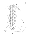
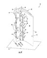
- Fig. 3 provides a perspective view of the airfoil 10 according to a second embodiment of the present invention.
- the airfoil 10 again includes the platform or sidewall 12, interior surface 16, exterior surface 18, pressure side 20, suction side 22, overlapping pressure side trench segments 46, and side cooling passages 58 as previously described and illustrated in Fig. 1 .
- the overlapping stagnation trench segments 40 lie along at least a portion of the stagnation line 24 and then curve in alternating directions toward the pressure and suctions sides 20, 22.
- the stagnation trench segments 40 may include a branch at a discreet angle and then continue as a straight trench.
- the cooling passages 44 in each stagnation trench segment 40 again provide fluid communication from the interior surface 16 to the exterior surface 18 to enhance film cooling through the stagnation trench segments 40 along the stagnation line 24.
- each trench segment 40, 46, 50 generally includes opposing walls 62 that define a depression or groove in the exterior surface 18.
- the opposing walls 62 may be straight or curved and may define a constant or varying width for the trench segments 40, 46, 50.
- the cooling passages 44, 58 in adjacent trench segments 40, 46, 50 may be radially aligned with or offset from one another.
- Each cooling passage 44, 58 may include a first section 64 that terminates at the interior surface 16 and a second section 66 that terminates at the exterior surface 18.
- the first section 64 may have a cylindrical shape, and the second section 66 may have a conical or spherical shape. As shown in Fig. 5 , the first section 64 may be angled with respect to the second section 66 and/or the trench segment 40, 46, 50 to provide directional flow for the cooling media flowing through the cooling passage 44, 58 and into the trench segment 40, 46, 50. Alternately or in addition, the second section 66 and/or the walls 62 of the trench segment 40, 46, 50 may be asymmetric to preferentially distribute the cooling media across the exterior surface 18.
- One or more of the cooling passages 44, 58 may be angled with respect to the trench segments 40, 46, 50 to preferentially direct the cooling media in the trench segments 40, 46, 50.
- the cooling passages 44 in the stagnation trench segments 40 may be angled radially outward so that the cooling media flows radially outward in the stagnation trench segments 40.
- the depth of the stagnation trench segments 40 may gradually decrease and/or the width may gradually increase as the stagnation trench segments 40 extend radially outward. In this manner, the angled cooling passages 44, in combination with the varying width and/or depth of the trench segments 40, enhance the distribution of the cooling media along the exterior surface 18.
- each stagnation trench segment 40 again lies along at least a portion of the stagnation line 24 and branch portions 70 extend at angles in opposite directions toward the pressure and suction sides 20, 22 of the airfoil 10. In this manner, the branch portions 70 radially overlap with the next radially outward stagnation trench segment 40 to enhance distribution of the film cooling across the exterior surface 18 of the airfoil 10.
- each stagnation trench segment 40 again includes the branch portions 70 that extend at angles in opposite directions toward the pressure and suction sides 20, 22 of the airfoil 10, as previously shown in Fig. 6 .
- each stagnation trench segment 40 again includes the branch portions 70; however, the branch portions 70 extend at angles in alternating directions toward the pressure and suction sides 20, 22 of the airfoil 10.
- the stagnation trench segment 40 may include multiple cooling passages 44, with each cooling passage located radially between consecutive branch portions 70.
- Fig. 9 provides an additional embodiment of the pressure side trench segments 46 that may or may not be incorporated into any of the previous embodiments.
- the overlapping pressure side trench segments 46 may be aligned substantially perpendicular to the direction of airflow across the airfoil 10, and each pressure side trench segment 46 may further include one or more branch portions 72 that extend at an angle toward the trailing edge 26. In this manner, the branch portions 72 radially overlap with the next radially outward pressure side trench segment 46 to enhance distribution of the film cooling across the pressure side 20 of the airfoil 10.
- the airfoil 10 may similarly include suction side trench segments 50 with similar branch portions 72 that extend at an angle toward the trailing edge 26 on the suction side 22 of the exterior surface 18.
- suction side trench segments 50 with similar branch portions 72 that extend at an angle toward the trailing edge 26 on the suction side 22 of the exterior surface 18.
- Fig. 10 provides a simplified cross-section view of an exemplary gas turbine 80 that may incorporate various embodiments of the present invention.
- the gas turbine 80 may generally include a compressor section 82 at the front, a combustion section 84 radially disposed around the middle, and a turbine section 86 at the rear.
- the compressor section 82 and the turbine section 86 may share a common rotor 88 connected to a generator 90 to produce electricity.
- the compressor section 82 may include an axial flow compressor in which a working fluid 92, such as ambient air, enters the compressor and passes through alternating stages of stationary vanes 94 and rotating blades 96.
- a compressor casing 98 may contain the working fluid 92 as the stationary vanes 94 and rotating blades 96 accelerate and redirect the working fluid 92 to produce a continuous flow of compressed working fluid 92.
- the majority of the compressed working fluid 92 flows through a compressor discharge plenum 100 to the combustion section 84.
- the combustion section 84 may include any type of combustor known in the art.
- a combustor casing 102 may circumferentially surround some or all of the combustion section 84 to contain the compressed working fluid 92 flowing from the compressor section 82.
- One or more fuel nozzles 104 may be radially arranged in an end cover 106 to supply fuel to a combustion chamber 108 downstream from the fuel nozzles 104.
- Possible fuels include, for example, one or more of blast furnace gas, coke oven gas, natural gas, vaporized liquefied natural gas (LNG), hydrogen, and propane.
- the compressed working fluid 92 may flow from the compressor discharge passage 100 along the outside of the combustion chamber 108 before reaching the end cover 106 and reversing direction to flow through the fuel nozzles 104 to mix with the fuel.
- the mixture of fuel and compressed working fluid 92 flows into the combustion chamber 108 where it ignites to generate combustion gases having a high temperature and pressure.
- a transition duct 110 circumferentially surrounds at least a portion of the combustion chamber 108, and the combustion gases flow through the transition duct 110 to the turbine section 86.
- the turbine section 86 may include alternating stages of rotating buckets 112 and stationary nozzles 114.
- the transition duct 110 redirects and focuses the combustion gases onto the first stage of rotating buckets 112.
- the combustion gases expand, causing the rotating buckets 112 and rotor 88 to rotate.
- the combustion gases then flow to the next stage of stationary nozzles 114 which redirect the combustion gases to the next stage of rotating buckets 112, and the process repeats for the following stages.
Abstract
Description
- The present invention generally involves an airfoil, such as might be used in a turbine.
- Turbines are widely used in a variety of aviation, industrial, and power generation applications to perform work. Each turbine generally includes alternating stages of circumferentially mounted stator vanes and rotating blades. Each stator vane and rotating blade may include high alloy steel and/or ceramic material shaped into an airfoil. A compressed working fluid, such as steam, combustion gases, or air, flows across the stator vanes and rotating blades along a gas path in the turbine. The stator vanes accelerate and direct the compressed working fluid onto the subsequent stage of rotating blades to impart motion to the rotating blades and perform work.
- High temperatures associated with the compressed working fluid may lead to increased wear and/or damage to the stator vanes and/or rotating blades. As a result, a cooling media may be supplied inside the airfoils and released through the airfoils to provide film cooling to the outside of the airfoils. Trenches in the airfoils evenly distribute the cooling media across the external surface of the airfoils. However, an improved airfoil that varies the distribution of the cooling media across the external surface of the airfoils would be useful.
- Aspects and advantages of the invention are set forth below in the following description, or may be obvious from the description, or may be learned through practice of the invention.
- One aspect of the present invention is an airfoil that includes an interior surface, an exterior surface opposed to the interior surface, a pressure side, a suction side opposed to the pressure side, a stagnation line between the pressure and suction sides, and a trailing edge between the pressure and suction sides and downstream from the stagnation line. A first column of overlapping stagnation trench segments is on the exterior surface, and the stagnation line passes through at least a portion of each of the overlapping stagnation trench segments. At least one cooling passage in each stagnation trench segment provides fluid communication from the interior surface to the exterior surface.
- Another aspect of the present invention is an airfoil that includes an interior surface, an exterior surface opposed to the interior surface, a pressure side, a suction side opposed to the pressure side, a stagnation line between the pressure and suction sides, and a trailing edge between the pressure and suction sides and downstream from the stagnation line. A second column of overlapping pressure side trench segments is on the pressure side, and a third column of overlapping suction side trench segments is on the suction side. Each pressure side trench segment and each suction side trench segment has a first end and a second end downstream and radially outward from the first end. At least one side cooling passage is in each pressure side trench segment and in each suction side trench segment, and the side cooling passages provide fluid communication from the interior surface to the exterior surface.
- In yet another aspect, an airfoil includes an interior surface, an exterior surface opposed to the interior surface, a pressure side, a suction side opposed to the pressure side, a stagnation line between the pressure and suction sides, and a trailing edge between the pressure and suction sides and downstream from the stagnation line. A first column of overlapping stagnation trench segments is on the exterior surface, and the stagnation line passes through at least a portion of each of the overlapping stagnation trench segments. At least one cooling passage is in each stagnation trench segment and provides fluid communication from the interior surface to the exterior surface. A second column of overlapping pressure side trench segments is on the pressure side, and a third column of overlapping suction side trench segments is on the suction side. At least one side cooling passage is in each pressure side trench segment and in each suction side trench segment to provide fluid communication from the interior surface to the exterior surface.
- Those of ordinary skill in the art will better appreciate the features and aspects of such embodiments, and others, upon review of the specification.
- A full and enabling disclosure of the present invention, including the best mode thereof to one skilled in the art, is set forth more particularly in the remainder of the specification, including reference to the accompanying figures, in which:
-
Fig. 1 is a perspective view of an airfoil according to one embodiment of the present invention; -
Fig. 2 is a perspective view of the suction side of the airfoil shown inFig. 1 according to one embodiment of the present invention; -
Fig. 3 is a perspective view of an airfoil according to a second embodiment of the present invention; -
Fig. 4 is an axial cross-section view of the airfoil shown inFig. 1 taken along line A-A; -
Fig. 5 is a radial cross-section view of the airfoil shown inFig. 1 taken along line B-B; -
Fig. 6 is a perspective view of an airfoil according to a third embodiment of the present invention; -
Fig. 7 is a perspective view of an airfoil according to a fourth embodiment of the present invention; -
Fig. 8 is a perspective view of an airfoil according to a fifth embodiment of the present invention; and -
Fig. 9 is a perspective view of an airfoil according to a sixth embodiment of the present invention; and -
Fig. 10 is a cross section view of an exemplary gas turbine incorporating any embodiment of the present invention. - Reference will now be made in detail to present embodiments of the invention, one or more examples of which are illustrated in the accompanying drawings. The detailed description uses numerical and letter designations to refer to features in the drawings. Like or similar designations in the drawings and description have been used to refer to like or similar parts of the invention. As used herein, the terms "first", "second", and "third" may be used interchangeably to distinguish one component from another and are not intended to signify location or importance of the individual components. In addition, the terms "upstream" and "downstream" refer to the relative location of components in a fluid pathway. For example, component A is upstream from component B if a fluid flows from component A to component B. Conversely, component B is downstream from component A if component B receives a fluid flow from component A.
- Each example is provided by way of explanation of the invention, not limitation of the invention. In fact, it will be apparent to those skilled in the art that modifications and variations can be made in the present invention without departing from the scope or spirit thereof. For instance, features illustrated or described as part of one embodiment may be used on another embodiment to yield a still further embodiment. Thus, it is intended that the present invention covers such modifications and variations as come within the scope of the appended claims and their equivalents.
-
Fig. 1 provides a perspective view of anairfoil 10 according to one embodiment of the present invention, andFig. 2 provides a perspective view of the suction side of the airfoil shown inFig. 1 . Theairfoil 10 may be used, for example, as a rotating blade or stationary vane in a turbine to convert kinetic energy associated with a compressed working fluid into mechanical energy. The compressed working fluid may be steam, combustion gases, air, or any other fluid having kinetic energy. As shown inFigs. 1 and2 , theairfoil 10 is generally connected to a platform orsidewall 12. The platform orsidewall 12 generally serves as the radial boundary for a gas path inside the turbine and provides an attachment point for theairfoil 10. Theairfoil 10 may include aninterior surface 16 and anexterior surface 18 opposed to theinterior surface 16 and connected to theplatform 12. The exterior surface generally includes apressure side 20 and asuction side 22 opposed to thepressure side 20. As shown inFigs. 1 and2 , thepressure side 20 is generally concave, and thesuction side 22 is generally convex to provide an aerodynamic surface over which the compressed working fluid flows. Astagnation line 24 at a leading edge of theairfoil 10 between the pressure andsuction sides pressure side 20 and fluid flow across thesuction side 22 of theairfoil 10. Thestagnation line 24 often has the highest temperature over theexterior surface 18 of theairfoil 10. Atrailing edge 26 is between the pressure andsuction sides stagnation line 24. In this manner, theexterior surface 18 creates an aerodynamic surface suitable for converting the kinetic energy associated with the compressed working fluid into mechanical energy. - The
exterior surface 18 generally includes aradial length 30 that extends from theplatform 12 radially outward and anaxial length 32 that extends from thestagnation line 24 to thetrailing edge 26. One or more columns of trench segments may extend radially and/or axially in theexterior surface 18, and each trench segment may include at least one cooling passage that provides fluid communication from theinterior surface 16 to theexterior surface 18. In this manner, cooling media may be supplied inside theairfoil 10, and the cooling passages allow the cooling media to flow through theairfoil 10 to provide film cooling to theexterior surface 18. The trench segments may be located anywhere on theairfoil 10 and/or platform orsidewall 12, may be straight or arcuate, and may be aligned or staggered with respect to one another. In addition, the trench segments may have varying lengths, widths, and/or depths. The varying lengths, widths, and/or depths of the trench segments alter the distribution of the cooling media across theexterior surface 18. For example, widening the trench segments and making them shallower as they move away from the cooling passages may assist in diffusing the cooling media across theexterior surface 18. - In the particular embodiment shown in
Fig. 1 , for example, overlappingstagnation trench segments 40 may be arranged in afirst column 42 on theexterior surface 18 so that thestagnation line 24 passes through at least a portion of each of thestagnation trench segments 40. Eachstagnation trench segment 40 may be substantially straight and canted at an angle with respect to the immediately adjacentstagnation trench segment 40 so that thestagnation trench segments 40 overlap one another radially along theexterior surface 18. As used herein, the term "overlap" means that moving radially outward from theplatform 12, the end of onetrench segment 40 is radially outward of the beginning of thenext trench segment 40 in the same column. At least onecooling passage 44 in eachstagnation trench segment 40 may provide fluid communication from theinterior surface 16 to theexterior surface 18. In this manner, thecooling passages 44 may provide substantially continuous film cooling through thestagnation trench segments 40 along thestagnation line 24. - Additional overlapping trench segments may be arranged on the pressure and/or
suction sides exterior surface 18. For example, as shown inFig. 1 , overlapping pressureside trench segments 46 may be arranged in asecond column 48 on thepressure side 20 of theexterior surface 18. Alternately or in addition, overlapping suctionside trench segments 50 may be arranged in athird column 52 on thesuction side 22 of theexterior surface 18, as shown inFig. 2 . Each pressureside trench segment 46 and each suctionside trench segment 50 may be canted or angled in the opposite direction. For example, as shown inFigs. 1 and2 , each pressureside trench segment 46 and/or each suctionside trench segment 50 may have afirst end 54 and asecond end 56 downstream and radially outward from thefirst end 54. In addition, each pressureside trench segment 46 and/or each suctionside trench segment 50 may include one or moreside cooling passages 58 that provide fluid communication from theinterior surface 16 to theexterior surface 18 to provide film cooling over the pressure andsuction sides Fig. 1 , theside cooling passages 58 in the pressureside trench segments 46 are radially offset from thecooling passages 44 in thestagnation trench segments 40 to further enhance radial distribution of the cooling media over theexterior surface 18. -
Fig. 3 provides a perspective view of theairfoil 10 according to a second embodiment of the present invention. As shown, theairfoil 10 again includes the platform orsidewall 12,interior surface 16,exterior surface 18,pressure side 20,suction side 22, overlapping pressureside trench segments 46, andside cooling passages 58 as previously described and illustrated inFig. 1 . In this particular embodiment, the overlappingstagnation trench segments 40 lie along at least a portion of thestagnation line 24 and then curve in alternating directions toward the pressure and suctionssides stagnation trench segments 40 may include a branch at a discreet angle and then continue as a straight trench. Thecooling passages 44 in eachstagnation trench segment 40 again provide fluid communication from theinterior surface 16 to theexterior surface 18 to enhance film cooling through thestagnation trench segments 40 along thestagnation line 24. -
Figs. 4 and5 provide axial and radial cross-section views of theairfoil 10 shown inFig. 1 taken along lines A-A and B-B, respectively. As shown most clearly inFigs. 4 and5 , eachtrench segment walls 62 that define a depression or groove in theexterior surface 18. The opposingwalls 62 may be straight or curved and may define a constant or varying width for thetrench segments cooling passages adjacent trench segments cooling passage first section 64 that terminates at theinterior surface 16 and asecond section 66 that terminates at theexterior surface 18. Thefirst section 64 may have a cylindrical shape, and thesecond section 66 may have a conical or spherical shape. As shown inFig. 5 , thefirst section 64 may be angled with respect to thesecond section 66 and/or thetrench segment cooling passage trench segment second section 66 and/or thewalls 62 of thetrench segment exterior surface 18. - One or more of the
cooling passages trench segments trench segments Fig. 5 , thecooling passages 44 in thestagnation trench segments 40 may be angled radially outward so that the cooling media flows radially outward in thestagnation trench segments 40. In addition, the depth of thestagnation trench segments 40 may gradually decrease and/or the width may gradually increase as thestagnation trench segments 40 extend radially outward. In this manner, the angledcooling passages 44, in combination with the varying width and/or depth of thetrench segments 40, enhance the distribution of the cooling media along theexterior surface 18. -
Figs. 6-8 provide additional embodiments of thestagnation trench segments 40 within the scope of the present invention. In the particular embodiment shown inFig. 6 , eachstagnation trench segment 40 again lies along at least a portion of thestagnation line 24 andbranch portions 70 extend at angles in opposite directions toward the pressure andsuction sides airfoil 10. In this manner, thebranch portions 70 radially overlap with the next radially outwardstagnation trench segment 40 to enhance distribution of the film cooling across theexterior surface 18 of theairfoil 10. In the particular embodiment shown inFig. 7 , eachstagnation trench segment 40 again includes thebranch portions 70 that extend at angles in opposite directions toward the pressure andsuction sides airfoil 10, as previously shown inFig. 6 . In addition, two or more of thestagnation trench segments 40 are joined together, creating a longerstagnation trench segment 40 withmultiple cooling passages 44 andbranch portions 70. In the particular embodiment shown inFig. 8 , eachstagnation trench segment 40 again includes thebranch portions 70; however, thebranch portions 70 extend at angles in alternating directions toward the pressure andsuction sides airfoil 10. As further shown inFig. 8 , thestagnation trench segment 40 may includemultiple cooling passages 44, with each cooling passage located radially betweenconsecutive branch portions 70. -
Fig. 9 provides an additional embodiment of the pressureside trench segments 46 that may or may not be incorporated into any of the previous embodiments. As shown inFig. 9 , the overlapping pressureside trench segments 46 may be aligned substantially perpendicular to the direction of airflow across theairfoil 10, and each pressureside trench segment 46 may further include one ormore branch portions 72 that extend at an angle toward the trailingedge 26. In this manner, thebranch portions 72 radially overlap with the next radially outward pressureside trench segment 46 to enhance distribution of the film cooling across thepressure side 20 of theairfoil 10. - Alternately or in addition, the
airfoil 10 may similarly include suctionside trench segments 50 withsimilar branch portions 72 that extend at an angle toward the trailingedge 26 on thesuction side 22 of theexterior surface 18. One of ordinary skill in the art will readily appreciate from the teachings herein that still further embodiments within the scope of the present invention may include one or more of the features previously described with respect to the embodiments shown inFigs. 1-5 . -
Fig. 10 provides a simplified cross-section view of anexemplary gas turbine 80 that may incorporate various embodiments of the present invention. As shown, thegas turbine 80 may generally include acompressor section 82 at the front, acombustion section 84 radially disposed around the middle, and aturbine section 86 at the rear. Thecompressor section 82 and theturbine section 86 may share acommon rotor 88 connected to agenerator 90 to produce electricity. - The
compressor section 82 may include an axial flow compressor in which a workingfluid 92, such as ambient air, enters the compressor and passes through alternating stages ofstationary vanes 94 androtating blades 96. Acompressor casing 98 may contain the workingfluid 92 as thestationary vanes 94 androtating blades 96 accelerate and redirect the workingfluid 92 to produce a continuous flow of compressed workingfluid 92. The majority of the compressed workingfluid 92 flows through acompressor discharge plenum 100 to thecombustion section 84. - The
combustion section 84 may include any type of combustor known in the art. For example, as shown inFig. 10 , acombustor casing 102 may circumferentially surround some or all of thecombustion section 84 to contain the compressed workingfluid 92 flowing from thecompressor section 82. One ormore fuel nozzles 104 may be radially arranged in anend cover 106 to supply fuel to acombustion chamber 108 downstream from thefuel nozzles 104. Possible fuels include, for example, one or more of blast furnace gas, coke oven gas, natural gas, vaporized liquefied natural gas (LNG), hydrogen, and propane. The compressed workingfluid 92 may flow from thecompressor discharge passage 100 along the outside of thecombustion chamber 108 before reaching theend cover 106 and reversing direction to flow through thefuel nozzles 104 to mix with the fuel. The mixture of fuel and compressed workingfluid 92 flows into thecombustion chamber 108 where it ignites to generate combustion gases having a high temperature and pressure. Atransition duct 110 circumferentially surrounds at least a portion of thecombustion chamber 108, and the combustion gases flow through thetransition duct 110 to theturbine section 86. - The
turbine section 86 may include alternating stages of rotatingbuckets 112 andstationary nozzles 114. As will be described in more detail, thetransition duct 110 redirects and focuses the combustion gases onto the first stage of rotatingbuckets 112. As the combustion gases pass over the first stage of rotatingbuckets 112, the combustion gases expand, causing therotating buckets 112 androtor 88 to rotate. The combustion gases then flow to the next stage ofstationary nozzles 114 which redirect the combustion gases to the next stage of rotatingbuckets 112, and the process repeats for the following stages. - This written description uses examples to disclose the invention, including the best mode, and also to enable any person skilled in the art to practice the invention, including making and using any devices or systems and performing any incorporated methods. The patentable scope of the invention is defined by the claims, and may include other examples that occur to those skilled in the art. Such other examples are intended to be within the scope of the claims if they include structural elements that do not differ from the literal language of the claims, or if they include equivalent structural elements with insubstantial differences from the literal languages of the claims.
- Various aspects and embodiments of the present invention are defined by the following numbered clauses:
- 1. An airfoil, comprising:
- a. an interior surface;
- b. an exterior surface opposed to the interior surface, wherein the exterior surface comprises a pressure side, a suction side opposed to the pressure side, a stagnation line between the pressure and suction sides, and a trailing edge between the pressure and suction sides and downstream from the stagnation line;
- c. a second column of overlapping pressure side trench segments on the pressure side;
- d. a third column of overlapping suction side trench segments on the suction side;
- e. wherein each pressure side trench segment and each suction side trench segment has a first end and a second end downstream and radially outward from the first end; and
- f. at least one side cooling passage in each pressure side trench segment and in each suction side trench segment, wherein the side cooling passages provide fluid communication from the interior surface to the exterior surface.
- 2. The airfoil as in clause 1, further comprising a first column of overlapping stagnation trench segments on the exterior surface, wherein the stagnation line passes through at least a portion of each of the overlapping stagnation trench segments.
- 3. The airfoil as in clause 1 or 2, wherein at least one stagnation trench segment is arcuate.
- 4. The airfoil as in any preceding clause, wherein at least one stagnation trench segment has a varying dimension along a length of the at least one stagnation trench segment.
- 5. The airfoil as in any preceding clause, wherein at least one stagnation trench segment has a decreasing dimension, and the at least one cooling passage in the at least one stagnation trench segment is angled toward the decreasing dimension.
- 6. The airfoil as in any preceding clause, further comprising at least one cooling passage in each stagnation trench segment, wherein the at least one cooling passage provides fluid communication from the interior surface to the exterior surface.
- 7. The airfoil as in any preceding clause, wherein the side cooling passages in the pressure side trench segments are radially offset from the cooling passages in the stagnation trench segments.
- 8. An airfoil, comprising:
- a. an interior surface;
- b. an exterior surface opposed to the interior surface, wherein the exterior surface comprises a pressure side, a suction side opposed to the pressure side, a stagnation line between the pressure and suction sides, and a trailing edge between the pressure and suction sides and downstream from the stagnation line;
- c. a first column of overlapping stagnation trench segments on the exterior surface, wherein the stagnation line passes through at least a portion of each of the overlapping stagnation trench segments;
- d. at least one cooling passage in each stagnation trench segment, wherein the at least one cooling passage provides fluid communication from the interior surface to the exterior surface;
- e. a second column of overlapping pressure side trench segments on the pressure side;
- f. a third column of overlapping suction side trench segments on the suction side; and
- g. at least one side cooling passage in each pressure side trench segment and in each suction side trench segment, wherein the side cooling passages provide fluid communication from the interior surface to the exterior surface.
- 9. The airfoil as in any preceding clause, wherein at least one stagnation trench segment is arcuate.
- 10. The airfoil as in any preceding clause, wherein at least one stagnation trench segment has a varying dimension along a length of the at least one stagnation trench segment.
- 11. The airfoil as in any preceding clause, wherein at least one stagnation trench segment has a decreasing dimension, and the at least one cooling passage in the at least one stagnation trench segment is angled toward the decreasing dimension.
- 12. The airfoil as in any preceding clause, wherein the side cooling passages in the pressure side trench segments are radially offset from the cooling passages in the stagnation trench segments.
Claims (8)
- An airfoil (10), comprising:a. an interior surface (16);b. an exterior surface (18) opposed to the interior surface (16), wherein the exterior surface (18) comprises a pressure side (20), a suction side (22) opposed to the pressure side (20), a stagnation line (24) between the pressure and suction sides (20, 22), and a trailing edge (26) between the pressure and suction sides (20, 22) and downstream from the stagnation line (24);c. a first column (42) of overlapping stagnation trench segments (40) on the exterior surface (18), wherein the stagnation line (24) passes through at least a portion of each of the overlapping stagnation trench segments (40); andd. at least one cooling passage (44) in each stagnation trench segment (40), wherein the cooling passages (44) provide fluid communication from the interior surface (16) to the exterior surface (18).
- The airfoil (10) as in claim 1, wherein at least one stagnation trench segment (40) is arcuate.
- The airfoil (10) as in claim 1 or 2, wherein at least one stagnation trench segment (40) has a varying dimension along a length (30, 32) of the at least one stagnation trench segment (40).
- The airfoil (10) as in claim 1, 2 or 3, wherein at least one stagnation trench segment (40) has a decreasing dimension, and the at least one cooling passage (44) in the at least one stagnation trench segment (40) is angled toward the decreasing dimension.
- The airfoil (10) as in any preceding claim, further comprising a second column (48) of overlapping pressure side trench segments (46) on the pressure side (20).
- The airfoil (10) as in claim 5, further comprising a third column (52) of overlapping suction side trench segments (50) on the suction side (22).
- The airfoil (10) as in any of claims 5 or 6, further comprising at least one side cooling passage (58) in each pressure side trench segment (46), wherein the side cooling passages (58) provide fluid communication from the interior surface (16) to the exterior surface (18).
- The airfoil (10) as in claim 7, wherein the side cooling passages (58) in the pressure side trench segments (46) are radially offset from the cooling passages (58) in the stagnation trench segments (40).
Applications Claiming Priority (1)
| Application Number | Priority Date | Filing Date | Title |
|---|---|---|---|
| US13/535,540 US9080451B2 (en) | 2012-06-28 | 2012-06-28 | Airfoil |
Publications (2)
| Publication Number | Publication Date |
|---|---|
| EP2679772A1 true EP2679772A1 (en) | 2014-01-01 |
| EP2679772B1 EP2679772B1 (en) | 2015-05-27 |
Family
ID=48740854
Family Applications (1)
| Application Number | Title | Priority Date | Filing Date |
|---|---|---|---|
| EP13172933.7A Active EP2679772B1 (en) | 2012-06-28 | 2013-06-20 | An airfoil |
Country Status (5)
| Country | Link |
|---|---|
| US (1) | US9080451B2 (en) |
| EP (1) | EP2679772B1 (en) |
| JP (1) | JP6216166B2 (en) |
| CN (1) | CN103527260B (en) |
| RU (1) | RU2611465C2 (en) |
Cited By (2)
| Publication number | Priority date | Publication date | Assignee | Title |
|---|---|---|---|---|
| EP3034794A1 (en) * | 2014-12-15 | 2016-06-22 | United Technologies Corporation | Gas turbine engine component and corresponding wall |
| EP3043026A3 (en) * | 2014-12-23 | 2016-09-28 | United Technologies Corporation | Gas turbine component, airfoil component and corresponding method of vectoring cooling air |
Families Citing this family (11)
| Publication number | Priority date | Publication date | Assignee | Title |
|---|---|---|---|---|
| BR112015031098A2 (en) * | 2013-07-03 | 2017-07-25 | Gen Electric | airfoil |
| JP5705945B1 (en) * | 2013-10-28 | 2015-04-22 | ミネベア株式会社 | Centrifugal fan |
| US10041356B2 (en) * | 2014-08-15 | 2018-08-07 | United Technologies Corporation | Showerhead hole scheme apparatus and system |
| US10451084B2 (en) * | 2015-11-16 | 2019-10-22 | General Electric Company | Gas turbine engine with vane having a cooling inlet |
| US10280763B2 (en) * | 2016-06-08 | 2019-05-07 | Ansaldo Energia Switzerland AG | Airfoil cooling passageways for generating improved protective film |
| KR101853550B1 (en) * | 2016-08-22 | 2018-04-30 | 두산중공업 주식회사 | Gas Turbine Blade |
| US20180230812A1 (en) * | 2017-01-13 | 2018-08-16 | General Electric Company | Film hole arrangement for a turbine engine |
| US10697301B2 (en) | 2017-04-07 | 2020-06-30 | General Electric Company | Turbine engine airfoil having a cooling circuit |
| US10570747B2 (en) * | 2017-10-02 | 2020-02-25 | DOOSAN Heavy Industries Construction Co., LTD | Enhanced film cooling system |
| US11401818B2 (en) * | 2018-08-06 | 2022-08-02 | General Electric Company | Turbomachine cooling trench |
| CN113898415B (en) | 2021-10-15 | 2022-06-28 | 上海交通大学 | Structure for improving aerodynamic efficiency of low-pressure turbine blade and working method thereof |
Citations (3)
| Publication number | Priority date | Publication date | Assignee | Title |
|---|---|---|---|---|
| EP1013877A2 (en) * | 1998-12-21 | 2000-06-28 | United Technologies Corporation | Hollow airfoil for a gas turbine engine |
| EP2154333A2 (en) * | 2008-08-14 | 2010-02-17 | United Technologies Corporation | Cooled airfoil and corresponding turbine assembly |
| US8087893B1 (en) * | 2009-04-03 | 2012-01-03 | Florida Turbine Technologies, Inc. | Turbine blade with showerhead film cooling holes |
Family Cites Families (15)
| Publication number | Priority date | Publication date | Assignee | Title |
|---|---|---|---|---|
| US5486093A (en) * | 1993-09-08 | 1996-01-23 | United Technologies Corporation | Leading edge cooling of turbine airfoils |
| US5374162A (en) | 1993-11-30 | 1994-12-20 | United Technologies Corporation | Airfoil having coolable leading edge region |
| US5458461A (en) | 1994-12-12 | 1995-10-17 | General Electric Company | Film cooled slotted wall |
| US6050777A (en) | 1997-12-17 | 2000-04-18 | United Technologies Corporation | Apparatus and method for cooling an airfoil for a gas turbine engine |
| US6210111B1 (en) | 1998-12-21 | 2001-04-03 | United Technologies Corporation | Turbine blade with platform cooling |
| US6234755B1 (en) * | 1999-10-04 | 2001-05-22 | General Electric Company | Method for improving the cooling effectiveness of a gaseous coolant stream, and related articles of manufacture |
| US6994521B2 (en) * | 2003-03-12 | 2006-02-07 | Florida Turbine Technologies, Inc. | Leading edge diffusion cooling of a turbine airfoil for a gas turbine engine |
| RU2267616C1 (en) * | 2004-05-21 | 2006-01-10 | Федеральное государственное унитарное предприятие "Центральный институт авиационного моторостроения им. П.И. Баранова" | Turbine cooled blade |
| US7553534B2 (en) * | 2006-08-29 | 2009-06-30 | General Electric Company | Film cooled slotted wall and method of making the same |
| US20090246011A1 (en) * | 2008-03-25 | 2009-10-01 | General Electric Company | Film cooling of turbine components |
| US20110097188A1 (en) | 2009-10-23 | 2011-04-28 | General Electric Company | Structure and method for improving film cooling using shallow trench with holes oriented along length of trench |
| US8608443B2 (en) * | 2010-06-11 | 2013-12-17 | Siemens Energy, Inc. | Film cooled component wall in a turbine engine |
| JP5517163B2 (en) * | 2010-10-07 | 2014-06-11 | 株式会社日立製作所 | Cooling hole machining method for turbine blade |
| US8870536B2 (en) * | 2012-01-13 | 2014-10-28 | General Electric Company | Airfoil |
| US8870535B2 (en) * | 2012-01-13 | 2014-10-28 | General Electric Company | Airfoil |
-
2012
- 2012-06-28 US US13/535,540 patent/US9080451B2/en active Active
-
2013
- 2013-06-20 EP EP13172933.7A patent/EP2679772B1/en active Active
- 2013-06-24 JP JP2013131234A patent/JP6216166B2/en active Active
- 2013-06-27 RU RU2013129242A patent/RU2611465C2/en not_active IP Right Cessation
- 2013-06-28 CN CN201310268845.4A patent/CN103527260B/en active Active
Patent Citations (3)
| Publication number | Priority date | Publication date | Assignee | Title |
|---|---|---|---|---|
| EP1013877A2 (en) * | 1998-12-21 | 2000-06-28 | United Technologies Corporation | Hollow airfoil for a gas turbine engine |
| EP2154333A2 (en) * | 2008-08-14 | 2010-02-17 | United Technologies Corporation | Cooled airfoil and corresponding turbine assembly |
| US8087893B1 (en) * | 2009-04-03 | 2012-01-03 | Florida Turbine Technologies, Inc. | Turbine blade with showerhead film cooling holes |
Cited By (4)
| Publication number | Priority date | Publication date | Assignee | Title |
|---|---|---|---|---|
| EP3034794A1 (en) * | 2014-12-15 | 2016-06-22 | United Technologies Corporation | Gas turbine engine component and corresponding wall |
| US11286790B2 (en) | 2014-12-15 | 2022-03-29 | Raytheon Technologies Corporation | Cooling passages for gas turbine engine component |
| EP3043026A3 (en) * | 2014-12-23 | 2016-09-28 | United Technologies Corporation | Gas turbine component, airfoil component and corresponding method of vectoring cooling air |
| US9976423B2 (en) | 2014-12-23 | 2018-05-22 | United Technologies Corporation | Airfoil showerhead pattern apparatus and system |
Also Published As
| Publication number | Publication date |
|---|---|
| JP6216166B2 (en) | 2017-10-18 |
| US20140003960A1 (en) | 2014-01-02 |
| EP2679772B1 (en) | 2015-05-27 |
| RU2611465C2 (en) | 2017-02-22 |
| CN103527260B (en) | 2017-03-01 |
| US9080451B2 (en) | 2015-07-14 |
| JP2014009689A (en) | 2014-01-20 |
| CN103527260A (en) | 2014-01-22 |
| RU2013129242A (en) | 2015-01-10 |
Similar Documents
| Publication | Publication Date | Title |
|---|---|---|
| EP2679772B1 (en) | An airfoil | |
| EP2615244B1 (en) | Film cooled turbine airfoil having a plurality of trenches on the exterior surface | |
| CN106894847B (en) | Turbine and turbine nozzle thereof | |
| EP2615245B1 (en) | Film cooled turbine airfoil having trench segments on the exterior surface | |
| JP6650687B2 (en) | Rotor blade cooling | |
| CN107084004B (en) | Impingement hole for a turbine engine component | |
| JP2010156335A (en) | Method and device concerning contour of improved turbine blade platform | |
| CN106894843B (en) | Turbine and turbine blade thereof | |
| EP3181815A1 (en) | Engine component for a gas turbine engine | |
| CA2927035C (en) | Rotor assembly with wear member | |
| CA2927037C (en) | Rotor assembly with scoop | |
| JP6446174B2 (en) | Compressor fairing segment | |
| EP2578815A2 (en) | Exhaust gas diffuser | |
| EP3205824A1 (en) | Accelerator insert for a gas turbine engine airfoil | |
| US10329922B2 (en) | Gas turbine engine airfoil | |
| CN111828098A (en) | Turbine engine airfoil having trailing edge | |
| EP3186484A1 (en) | Controlled convergence compressor flowpath for a gas turbine engine | |
| EP3184736A1 (en) | Angled heat transfer pedestal | |
| US20180230812A1 (en) | Film hole arrangement for a turbine engine | |
| EP3168416B1 (en) | Gas turbine | |
| EP3196411A2 (en) | Flow alignment devices to improve diffuser performance | |
| CN103206261B (en) | airfoil | |
| EP2713016B1 (en) | Exhaust diffuser arrangement for a turbine system and method of redirecting a flow |
Legal Events
| Date | Code | Title | Description |
|---|---|---|---|
| PUAI | Public reference made under article 153(3) epc to a published international application that has entered the european phase |
Free format text: ORIGINAL CODE: 0009012 |
|
| AK | Designated contracting states |
Kind code of ref document: A1 Designated state(s): AL AT BE BG CH CY CZ DE DK EE ES FI FR GB GR HR HU IE IS IT LI LT LU LV MC MK MT NL NO PL PT RO RS SE SI SK SM TR |
|
| AX | Request for extension of the european patent |
Extension state: BA ME |
|
| 17P | Request for examination filed |
Effective date: 20140701 |
|
| RBV | Designated contracting states (corrected) |
Designated state(s): AL AT BE BG CH CY CZ DE DK EE ES FI FR GB GR HR HU IE IS IT LI LT LU LV MC MK MT NL NO PL PT RO RS SE SI SK SM TR |
|
| RIC1 | Information provided on ipc code assigned before grant |
Ipc: F01D 5/18 20060101AFI20141216BHEP |
|
| GRAP | Despatch of communication of intention to grant a patent |
Free format text: ORIGINAL CODE: EPIDOSNIGR1 |
|
| INTG | Intention to grant announced |
Effective date: 20150129 |
|
| GRAS | Grant fee paid |
Free format text: ORIGINAL CODE: EPIDOSNIGR3 |
|
| GRAA | (expected) grant |
Free format text: ORIGINAL CODE: 0009210 |
|
| AK | Designated contracting states |
Kind code of ref document: B1 Designated state(s): AL AT BE BG CH CY CZ DE DK EE ES FI FR GB GR HR HU IE IS IT LI LT LU LV MC MK MT NL NO PL PT RO RS SE SI SK SM TR |
|
| REG | Reference to a national code |
Ref country code: GB Ref legal event code: FG4D |
|
| REG | Reference to a national code |
Ref country code: CH Ref legal event code: EP |
|
| REG | Reference to a national code |
Ref country code: AT Ref legal event code: REF Ref document number: 728982 Country of ref document: AT Kind code of ref document: T Effective date: 20150615 |
|
| REG | Reference to a national code |
Ref country code: IE Ref legal event code: FG4D |
|
| REG | Reference to a national code |
Ref country code: DE Ref legal event code: R096 Ref document number: 602013001838 Country of ref document: DE |
|
| REG | Reference to a national code |
Ref country code: AT Ref legal event code: MK05 Ref document number: 728982 Country of ref document: AT Kind code of ref document: T Effective date: 20150527 |
|
| REG | Reference to a national code |
Ref country code: LT Ref legal event code: MG4D |
|
| PG25 | Lapsed in a contracting state [announced via postgrant information from national office to epo] |
Ref country code: HR Free format text: LAPSE BECAUSE OF FAILURE TO SUBMIT A TRANSLATION OF THE DESCRIPTION OR TO PAY THE FEE WITHIN THE PRESCRIBED TIME-LIMIT Effective date: 20150527 Ref country code: NO Free format text: LAPSE BECAUSE OF FAILURE TO SUBMIT A TRANSLATION OF THE DESCRIPTION OR TO PAY THE FEE WITHIN THE PRESCRIBED TIME-LIMIT Effective date: 20150827 Ref country code: LT Free format text: LAPSE BECAUSE OF FAILURE TO SUBMIT A TRANSLATION OF THE DESCRIPTION OR TO PAY THE FEE WITHIN THE PRESCRIBED TIME-LIMIT Effective date: 20150527 Ref country code: FI Free format text: LAPSE BECAUSE OF FAILURE TO SUBMIT A TRANSLATION OF THE DESCRIPTION OR TO PAY THE FEE WITHIN THE PRESCRIBED TIME-LIMIT Effective date: 20150527 Ref country code: ES Free format text: LAPSE BECAUSE OF FAILURE TO SUBMIT A TRANSLATION OF THE DESCRIPTION OR TO PAY THE FEE WITHIN THE PRESCRIBED TIME-LIMIT Effective date: 20150527 Ref country code: PT Free format text: LAPSE BECAUSE OF FAILURE TO SUBMIT A TRANSLATION OF THE DESCRIPTION OR TO PAY THE FEE WITHIN THE PRESCRIBED TIME-LIMIT Effective date: 20150928 |
|
| REG | Reference to a national code |
Ref country code: NL Ref legal event code: MP Effective date: 20150527 |
|
| PG25 | Lapsed in a contracting state [announced via postgrant information from national office to epo] |
Ref country code: LV Free format text: LAPSE BECAUSE OF FAILURE TO SUBMIT A TRANSLATION OF THE DESCRIPTION OR TO PAY THE FEE WITHIN THE PRESCRIBED TIME-LIMIT Effective date: 20150527 Ref country code: AT Free format text: LAPSE BECAUSE OF FAILURE TO SUBMIT A TRANSLATION OF THE DESCRIPTION OR TO PAY THE FEE WITHIN THE PRESCRIBED TIME-LIMIT Effective date: 20150527 Ref country code: GR Free format text: LAPSE BECAUSE OF FAILURE TO SUBMIT A TRANSLATION OF THE DESCRIPTION OR TO PAY THE FEE WITHIN THE PRESCRIBED TIME-LIMIT Effective date: 20150828 Ref country code: BG Free format text: LAPSE BECAUSE OF FAILURE TO SUBMIT A TRANSLATION OF THE DESCRIPTION OR TO PAY THE FEE WITHIN THE PRESCRIBED TIME-LIMIT Effective date: 20150827 Ref country code: IS Free format text: LAPSE BECAUSE OF FAILURE TO SUBMIT A TRANSLATION OF THE DESCRIPTION OR TO PAY THE FEE WITHIN THE PRESCRIBED TIME-LIMIT Effective date: 20150927 Ref country code: RS Free format text: LAPSE BECAUSE OF FAILURE TO SUBMIT A TRANSLATION OF THE DESCRIPTION OR TO PAY THE FEE WITHIN THE PRESCRIBED TIME-LIMIT Effective date: 20150527 |
|
| PG25 | Lapsed in a contracting state [announced via postgrant information from national office to epo] |
Ref country code: DK Free format text: LAPSE BECAUSE OF FAILURE TO SUBMIT A TRANSLATION OF THE DESCRIPTION OR TO PAY THE FEE WITHIN THE PRESCRIBED TIME-LIMIT Effective date: 20150527 Ref country code: EE Free format text: LAPSE BECAUSE OF FAILURE TO SUBMIT A TRANSLATION OF THE DESCRIPTION OR TO PAY THE FEE WITHIN THE PRESCRIBED TIME-LIMIT Effective date: 20150527 Ref country code: IT Free format text: LAPSE BECAUSE OF FAILURE TO SUBMIT A TRANSLATION OF THE DESCRIPTION OR TO PAY THE FEE WITHIN THE PRESCRIBED TIME-LIMIT Effective date: 20150527 |
|
| PG25 | Lapsed in a contracting state [announced via postgrant information from national office to epo] |
Ref country code: CZ Free format text: LAPSE BECAUSE OF FAILURE TO SUBMIT A TRANSLATION OF THE DESCRIPTION OR TO PAY THE FEE WITHIN THE PRESCRIBED TIME-LIMIT Effective date: 20150527 Ref country code: MC Free format text: LAPSE BECAUSE OF FAILURE TO SUBMIT A TRANSLATION OF THE DESCRIPTION OR TO PAY THE FEE WITHIN THE PRESCRIBED TIME-LIMIT Effective date: 20150527 Ref country code: SK Free format text: LAPSE BECAUSE OF FAILURE TO SUBMIT A TRANSLATION OF THE DESCRIPTION OR TO PAY THE FEE WITHIN THE PRESCRIBED TIME-LIMIT Effective date: 20150527 Ref country code: PL Free format text: LAPSE BECAUSE OF FAILURE TO SUBMIT A TRANSLATION OF THE DESCRIPTION OR TO PAY THE FEE WITHIN THE PRESCRIBED TIME-LIMIT Effective date: 20150527 Ref country code: RO Free format text: LAPSE BECAUSE OF NON-PAYMENT OF DUE FEES Effective date: 20150527 |
|
| REG | Reference to a national code |
Ref country code: DE Ref legal event code: R097 Ref document number: 602013001838 Country of ref document: DE |
|
| REG | Reference to a national code |
Ref country code: IE Ref legal event code: MM4A |
|
| PLBE | No opposition filed within time limit |
Free format text: ORIGINAL CODE: 0009261 |
|
| STAA | Information on the status of an ep patent application or granted ep patent |
Free format text: STATUS: NO OPPOSITION FILED WITHIN TIME LIMIT |
|
| PG25 | Lapsed in a contracting state [announced via postgrant information from national office to epo] |
Ref country code: IE Free format text: LAPSE BECAUSE OF NON-PAYMENT OF DUE FEES Effective date: 20150620 |
|
| 26N | No opposition filed |
Effective date: 20160301 |
|
| PG25 | Lapsed in a contracting state [announced via postgrant information from national office to epo] |
Ref country code: SI Free format text: LAPSE BECAUSE OF FAILURE TO SUBMIT A TRANSLATION OF THE DESCRIPTION OR TO PAY THE FEE WITHIN THE PRESCRIBED TIME-LIMIT Effective date: 20150527 |
|
| PG25 | Lapsed in a contracting state [announced via postgrant information from national office to epo] |
Ref country code: BE Free format text: LAPSE BECAUSE OF FAILURE TO SUBMIT A TRANSLATION OF THE DESCRIPTION OR TO PAY THE FEE WITHIN THE PRESCRIBED TIME-LIMIT Effective date: 20150527 |
|
| REG | Reference to a national code |
Ref country code: FR Ref legal event code: ST Effective date: 20160805 |
|
| PG25 | Lapsed in a contracting state [announced via postgrant information from national office to epo] |
Ref country code: FR Free format text: LAPSE BECAUSE OF NON-PAYMENT OF DUE FEES Effective date: 20150727 |
|
| PG25 | Lapsed in a contracting state [announced via postgrant information from national office to epo] |
Ref country code: MT Free format text: LAPSE BECAUSE OF FAILURE TO SUBMIT A TRANSLATION OF THE DESCRIPTION OR TO PAY THE FEE WITHIN THE PRESCRIBED TIME-LIMIT Effective date: 20150527 |
|
| PG25 | Lapsed in a contracting state [announced via postgrant information from national office to epo] |
Ref country code: HU Free format text: LAPSE BECAUSE OF FAILURE TO SUBMIT A TRANSLATION OF THE DESCRIPTION OR TO PAY THE FEE WITHIN THE PRESCRIBED TIME-LIMIT; INVALID AB INITIO Effective date: 20130620 |
|
| PG25 | Lapsed in a contracting state [announced via postgrant information from national office to epo] |
Ref country code: CY Free format text: LAPSE BECAUSE OF FAILURE TO SUBMIT A TRANSLATION OF THE DESCRIPTION OR TO PAY THE FEE WITHIN THE PRESCRIBED TIME-LIMIT Effective date: 20150527 Ref country code: SE Free format text: LAPSE BECAUSE OF FAILURE TO SUBMIT A TRANSLATION OF THE DESCRIPTION OR TO PAY THE FEE WITHIN THE PRESCRIBED TIME-LIMIT Effective date: 20150527 Ref country code: NL Free format text: LAPSE BECAUSE OF FAILURE TO SUBMIT A TRANSLATION OF THE DESCRIPTION OR TO PAY THE FEE WITHIN THE PRESCRIBED TIME-LIMIT Effective date: 20150527 |
|
| PG25 | Lapsed in a contracting state [announced via postgrant information from national office to epo] |
Ref country code: TR Free format text: LAPSE BECAUSE OF FAILURE TO SUBMIT A TRANSLATION OF THE DESCRIPTION OR TO PAY THE FEE WITHIN THE PRESCRIBED TIME-LIMIT Effective date: 20150527 |
|
| PG25 | Lapsed in a contracting state [announced via postgrant information from national office to epo] |
Ref country code: LU Free format text: LAPSE BECAUSE OF NON-PAYMENT OF DUE FEES Effective date: 20150620 |
|
| GBPC | Gb: european patent ceased through non-payment of renewal fee |
Effective date: 20170620 |
|
| PG25 | Lapsed in a contracting state [announced via postgrant information from national office to epo] |
Ref country code: GB Free format text: LAPSE BECAUSE OF NON-PAYMENT OF DUE FEES Effective date: 20170620 |
|
| PG25 | Lapsed in a contracting state [announced via postgrant information from national office to epo] |
Ref country code: SM Free format text: LAPSE BECAUSE OF FAILURE TO SUBMIT A TRANSLATION OF THE DESCRIPTION OR TO PAY THE FEE WITHIN THE PRESCRIBED TIME-LIMIT Effective date: 20150527 |
|
| PG25 | Lapsed in a contracting state [announced via postgrant information from national office to epo] |
Ref country code: MK Free format text: LAPSE BECAUSE OF FAILURE TO SUBMIT A TRANSLATION OF THE DESCRIPTION OR TO PAY THE FEE WITHIN THE PRESCRIBED TIME-LIMIT Effective date: 20150527 |
|
| PG25 | Lapsed in a contracting state [announced via postgrant information from national office to epo] |
Ref country code: AL Free format text: LAPSE BECAUSE OF FAILURE TO SUBMIT A TRANSLATION OF THE DESCRIPTION OR TO PAY THE FEE WITHIN THE PRESCRIBED TIME-LIMIT Effective date: 20150527 |
|
| PGFP | Annual fee paid to national office [announced via postgrant information from national office to epo] |
Ref country code: DE Payment date: 20220518 Year of fee payment: 10 |
|
| PGFP | Annual fee paid to national office [announced via postgrant information from national office to epo] |
Ref country code: CH Payment date: 20220702 Year of fee payment: 10 |
|
| REG | Reference to a national code |
Ref country code: DE Ref legal event code: R119 Ref document number: 602013001838 Country of ref document: DE |
|
| REG | Reference to a national code |
Ref country code: CH Ref legal event code: PL |