EP2679771A1 - Systems and methods to control flow in a rotor wheel - Google Patents
Systems and methods to control flow in a rotor wheel Download PDFInfo
- Publication number
- EP2679771A1 EP2679771A1 EP13171616.9A EP13171616A EP2679771A1 EP 2679771 A1 EP2679771 A1 EP 2679771A1 EP 13171616 A EP13171616 A EP 13171616A EP 2679771 A1 EP2679771 A1 EP 2679771A1
- Authority
- EP
- European Patent Office
- Prior art keywords
- memory alloy
- shape memory
- fluid
- fluid passages
- alloy valves
- Prior art date
- Legal status (The legal status is an assumption and is not a legal conclusion. Google has not performed a legal analysis and makes no representation as to the accuracy of the status listed.)
- Granted
Links
- 238000000034 method Methods 0.000 title claims description 14
- 239000012530 fluid Substances 0.000 claims abstract description 102
- 229910001285 shape-memory alloy Inorganic materials 0.000 claims abstract description 66
- 230000007704 transition Effects 0.000 claims description 18
- 230000004044 response Effects 0.000 claims description 15
- 230000001105 regulatory effect Effects 0.000 claims description 6
- 239000007789 gas Substances 0.000 description 21
- 239000000567 combustion gas Substances 0.000 description 6
- 238000001816 cooling Methods 0.000 description 3
- 230000000694 effects Effects 0.000 description 3
- 230000001419 dependent effect Effects 0.000 description 2
- 238000010586 diagram Methods 0.000 description 2
- 239000000446 fuel Substances 0.000 description 2
- 229910001566 austenite Inorganic materials 0.000 description 1
- 230000002457 bidirectional effect Effects 0.000 description 1
- 230000001276 controlling effect Effects 0.000 description 1
- 230000005611 electricity Effects 0.000 description 1
- 229910000734 martensite Inorganic materials 0.000 description 1
- 239000000463 material Substances 0.000 description 1
- 239000000203 mixture Substances 0.000 description 1
- 239000002520 smart material Substances 0.000 description 1
Images



Classifications
-
- F—MECHANICAL ENGINEERING; LIGHTING; HEATING; WEAPONS; BLASTING
- F01—MACHINES OR ENGINES IN GENERAL; ENGINE PLANTS IN GENERAL; STEAM ENGINES
- F01D—NON-POSITIVE DISPLACEMENT MACHINES OR ENGINES, e.g. STEAM TURBINES
- F01D5/00—Blades; Blade-carrying members; Heating, heat-insulating, cooling or antivibration means on the blades or the members
- F01D5/02—Blade-carrying members, e.g. rotors
- F01D5/08—Heating, heat-insulating or cooling means
- F01D5/085—Heating, heat-insulating or cooling means cooling fluid circulating inside the rotor
- F01D5/087—Heating, heat-insulating or cooling means cooling fluid circulating inside the rotor in the radial passages of the rotor disc
-
- F—MECHANICAL ENGINEERING; LIGHTING; HEATING; WEAPONS; BLASTING
- F02—COMBUSTION ENGINES; HOT-GAS OR COMBUSTION-PRODUCT ENGINE PLANTS
- F02C—GAS-TURBINE PLANTS; AIR INTAKES FOR JET-PROPULSION PLANTS; CONTROLLING FUEL SUPPLY IN AIR-BREATHING JET-PROPULSION PLANTS
- F02C7/00—Features, components parts, details or accessories, not provided for in, or of interest apart form groups F02C1/00 - F02C6/00; Air intakes for jet-propulsion plants
- F02C7/04—Air intakes for gas-turbine plants or jet-propulsion plants
- F02C7/057—Control or regulation
-
- F—MECHANICAL ENGINEERING; LIGHTING; HEATING; WEAPONS; BLASTING
- F04—POSITIVE - DISPLACEMENT MACHINES FOR LIQUIDS; PUMPS FOR LIQUIDS OR ELASTIC FLUIDS
- F04D—NON-POSITIVE-DISPLACEMENT PUMPS
- F04D29/00—Details, component parts, or accessories
- F04D29/02—Selection of particular materials
- F04D29/023—Selection of particular materials especially adapted for elastic fluid pumps
-
- F—MECHANICAL ENGINEERING; LIGHTING; HEATING; WEAPONS; BLASTING
- F04—POSITIVE - DISPLACEMENT MACHINES FOR LIQUIDS; PUMPS FOR LIQUIDS OR ELASTIC FLUIDS
- F04D—NON-POSITIVE-DISPLACEMENT PUMPS
- F04D29/00—Details, component parts, or accessories
- F04D29/26—Rotors specially for elastic fluids
- F04D29/32—Rotors specially for elastic fluids for axial flow pumps
- F04D29/321—Rotors specially for elastic fluids for axial flow pumps for axial flow compressors
-
- F—MECHANICAL ENGINEERING; LIGHTING; HEATING; WEAPONS; BLASTING
- F04—POSITIVE - DISPLACEMENT MACHINES FOR LIQUIDS; PUMPS FOR LIQUIDS OR ELASTIC FLUIDS
- F04D—NON-POSITIVE-DISPLACEMENT PUMPS
- F04D29/00—Details, component parts, or accessories
- F04D29/58—Cooling; Heating; Diminishing heat transfer
- F04D29/582—Cooling; Heating; Diminishing heat transfer specially adapted for elastic fluid pumps
- F04D29/584—Cooling; Heating; Diminishing heat transfer specially adapted for elastic fluid pumps cooling or heating the machine
-
- F—MECHANICAL ENGINEERING; LIGHTING; HEATING; WEAPONS; BLASTING
- F05—INDEXING SCHEMES RELATING TO ENGINES OR PUMPS IN VARIOUS SUBCLASSES OF CLASSES F01-F04
- F05D—INDEXING SCHEME FOR ASPECTS RELATING TO NON-POSITIVE-DISPLACEMENT MACHINES OR ENGINES, GAS-TURBINES OR JET-PROPULSION PLANTS
- F05D2300/00—Materials; Properties thereof
- F05D2300/10—Metals, alloys or intermetallic compounds
- F05D2300/17—Alloys
-
- F—MECHANICAL ENGINEERING; LIGHTING; HEATING; WEAPONS; BLASTING
- F05—INDEXING SCHEMES RELATING TO ENGINES OR PUMPS IN VARIOUS SUBCLASSES OF CLASSES F01-F04
- F05D—INDEXING SCHEME FOR ASPECTS RELATING TO NON-POSITIVE-DISPLACEMENT MACHINES OR ENGINES, GAS-TURBINES OR JET-PROPULSION PLANTS
- F05D2300/00—Materials; Properties thereof
- F05D2300/50—Intrinsic material properties or characteristics
- F05D2300/505—Shape memory behaviour
Definitions
- Embodiments of the present application relate generally to gas turbine engines and more particularly to systems and methods to control a flow in a rotor wheel.
- Gas turbines are widely used in industrial and commercial operations.
- a typical gas turbine includes a compressor at the front, one or more combustors around the middle, and a turbine at the rear.
- the compressor imparts kinetic energy to the working fluid (e.g., air) to produce a compressed working fluid at a highly energized state.
- the compressed working fluid exits the compressor and flows to the combustors where it mixes with fuel and ignites to generate combustion gases having a high temperature and pressure.
- the combustion gases flow to the turbine where they expand to produce work. For example, expansion of the combustion gases in the turbine may rotate a shaft connected to a generator to produce electricity.
- the compressor and the turbine typically share a common rotor which extends from near the front of the compressor, through the combustor section, to near the rear of the turbine.
- the rotor typically is configured to direct a portion of the working fluid through one or more cooling flow passages to cool various components of the gas turbine.
- the cooling flow passages are configured for base load conditions.
- a gas turbine system may include a rotor wheel having one or more impeller vanes radially disposed on the rotor wheel.
- the system may also include one or more fluid passages defined by adjacent impeller vanes.
- the one or more fluid passages may be radially disposed across the rotor wheel.
- the system may include one or more shape memory alloy valves disposed within each of the fluid passages.
- the one or more shape memory alloy valves may be configured to change shape to control a flow of fluid through the fluid passages.
- the gas turbine system may include a rotor including a number of rotor wheels.
- the system may also include one or more impeller vanes radially disposed on each of the rotor wheels.
- the system may also include one or more fluid passages defined by adjacent impeller vanes such that the one or more fluid passages are radially disposed across the rotor wheels.
- the system may include one or more shape memory alloy valves disposed within each of the fluid passages. The one or more shape memory alloy valves may be configured to change shape to control a flow of fluid through the fluid passages.
- the method may include positioning one or more shape memory alloy valves within one or more fluid passages of a rotor wheel.
- the method may also include regulating a configuration of the shape memory alloy valves to control a flow of fluid through the fluid passages.
- Fig. 1 provides a cross-section view of an exemplary gas turbine 10 to illustrate various embodiments herein.
- the gas turbine 10 may generally include a compressor 12, one or more combustors 14 downstream from the compressor 12, and a turbine 16 downstream from the combustors 14.
- the compressor 12 may generally include alternating stages of axially aligned stator vanes 18 and rotating blades 20.
- the stator vanes 18 may be circumferentially connected to a compressor casing 22, and the rotating blades 20 may be circumferentially connected to a rotor 24.
- the stator vanes 18 and rotating blades 20 may progressively impart kinetic energy to a working fluid (e.g., air) to produce a compressed working fluid at a highly energized state.
- a working fluid e.g., air
- the compressed working fluid may then flows to one or more combustors 14 radially arranged around the rotor 24 where it may mix with fuel and ignites to produce combustion gases having a high temperature and pressure.
- the combustion gases may exit the combustors 14 and flow along a hot gas path through the turbine 16.
- the turbine 16 may include alternating stages of axially aligned stator vanes 26 and rotating buckets 28.
- the stator vanes 26 may be circumferentially connected to a turbine casing 30, and the rotating buckets 28 may be circumferentially connected to the rotor 24. Each stage of stator vanes 26 may direct and accelerate the combustion gases onto the downstream stage of rotating buckets 28 to produce work.
- the rotor 24 may include a number of rotor bodies or wheels 32 axially aligned and connected to transmit torque between the turbine 16 and the compressor 12.
- Each rotor body or wheel 32 may include one or more cavities that form an axial bore 34 through the rotor 24.
- One or more of the adjacent rotor wheels 32 may include a fluid passage 36 that provides fluid communication between the compressor 12 and the bore 34.
- the diverted fluid may be used to pressurize the rotor cavities to produce a desired differential pressure between the rotor cavities and the hot gas path in the turbine 16.
- the diverted fluid may be used to provide cooling to various components in the turbine 16.
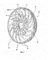
- Fig. 2 depicts a perspective view of the rotor wheel 32 according to one embodiment.
- the outer circumference of the rotor wheel 32 may include a number of dovetail slots 38 configured to receive the rotating blades 20.
- the radial face of the rotor wheel 32 may include one or more projections or impeller vanes 40 radially disposed on the rotor wheel 32.
- Each impeller vane 40 may include a first end 42 proximate to the bore 34.
- Adjacent projections or impeller vanes 40 on the surface of the rotor wheel 32 may define the fluid passages 36 radially across the rotor wheel 32. In this manner, in an example embodiment, as the rotor wheel 32 rotates counter-clockwise as shown in Fig. 2 , the impeller vanes 40 may divert a portion of the compressed working fluid through the fluid passages 36 to the bore 34.
- the fluid passage 36 may include a shape memory alloy valve 44. That is, the shape memory alloy valve 44 may be disposed between adjacent impeller vanes 40 and within of the fluid passage 36.
- the shape memory alloy valve 44 may be configured to change shape to control a flow of fluid 46 through the fluid passage 36.
- the shape memory alloy valve 44 may change shape in response to various load conditions of the gas turbine system, such as a base-load condition or a part-load condition. In other instances, the shape memory alloy valve 44 may change shape in response to various ambient temperature conditions, such as a cold day or a hot day.
- the shape memory alloy valve 44 may change shape in response to a temperature of the rotor wheel 32 or other components of the gas turbine engine, such as the compressor, turbine, or the like. Moreover, the shape memory alloy valve 44 may change shape in response to a pressure condition, a humidity condition, and/or a temperature of the flow of fluid 46. In this manner, the shape memory alloy valve 44 may provide an active flow control mechanism within the fluid passage 36 that is response to a number of conditions.
- the shape memory alloy valve 44 may include a first configuration above a transition temperature and a second configuration below the transition temperature.
- the shape memory alloy valve 44 may include one or more predetermined transition temperatures related to a load condition, an ambient temperature, a fluid temperature, a component temperature, a pressure condition, a humidity conditions, or a combination thereof, above or below which the shape memory alloy valve 44 may change shape to control the flow of fluid 46 through the fluid passage 36.
- the shape memory alloy valve 44 may also include a transition profile (e.g., a chart or graph), wherein the shape memory alloy valve 44 may change shape relative to a load condition, an ambient temperature, a fluid temperature, a component temperature, a pressure condition, a humidity conditions, or a combination thereof. That is, for example, as the load condition or temperature condition changes, the shape memory alloy valve 44 may also concurrently (or close thereto) change shape to regulate the flow of fluid 46.
- the shape memory alloy valve 44 may include a first element 48.
- the first element 48 may include a fixed end 50 secured about the fluid passage 36.
- the fixed end 50 may be secured to a wall of the impeller vane 40 or a surface of the fluid passage 36.
- the first element 48 may also include a free end 52.
- the free end 52 may be configured to move freely relative to the fixed end 50.
- the first element 48 may include a first configuration (as denoted by the solid lines) and a second configuration (as denoted by the dashed lines).
- the free end 52 may extend into the fluid passage 36 so as to obstruct and/or meter the flow of fluid 46.
- the free end 52 may not extend into the fluid passage 36.
- the shape and metering effect of the first element 48 may be dependent on any number of factors, including, but not limited to, a load condition, an ambient temperature, a component temperature, or the like.
- the first element 48 may change shape so as to gradually meter (e.g., increase or decrease) the fluid flow 46 as a load condition changes and/or an ambient temperature condition changes.
- the shape memory alloy valve 44 may include a second element 54.
- the second element 54 may be disposed opposite of the first element 48. Like the first element 48, the second element 54 may include a fixed end 56 secured about the fluid passage 36. The second element 54 may also include a free end 58. In this manner, the second element 54 may include a first configuration (as denoted by the solid lines) and a second configuration (as denoted by the dashed lines). In some instances, as denoted by the dashed lines, the free end 58 may extend into the fluid passage 36 so as to obstruct and/or meter the flow of fluid 46. In other instances, as denoted by the solid lines, the free end 58 may not extend into the fluid passage 36.
- the shape and metering effect of the second element 54 may be dependent on any number of factors, including, but not limited to, a load condition, an ambient temperature, a component temperature, or the like.
- the second element 54 may change shape so as to gradually meter (e.g., increase or decrease) the fluid flow 46 as a load condition changes or an ambient temperature condition changes.
- first element 48 and/or the second element 54 may each include a configuration that resembles a generally arcuate shape.
- the first element 48 and the second element 54 may independently or collectively meter the flow of fluid 46 within the fluid passage 36.
- first element 48 and the second element 54 may include similar or dissimilar transition temperatures and/or transition profiles. In this manner, the shape and metering effect of the first element 48 and the second element 54 may be the same or different at various load conditions and temperature conditions.
- shape memory alloy valves 44 may be disposed within each of the fluid passages 36.
- the shape memory alloy valves 44 may include any number of elements and/or configurations.
- the shape memory alloy valves 44 may be any configuration so as to meter and/or control the fluid flow 46 within the fluid passages 36. That is, any mechanism or device that is configured to change shape to meter the flow of fluid 46 within the fluid passage 36 based on a load condition and/or temperature condition is within the scope of this disclosure.
- one or more of the shape memory alloy valves 44 may be configured to change shape in a similar or dissimilar manner about various locations on the rotor wheel at different load conditions and temperature conditions.
- Shape memory alloys are materials that may change shape, stiffness, position, natural frequency, and other mechanical characteristics in response to, for example, temperature. Shape memory alloys are smart materials that may change shape based on a temperature due to changes in their microstructures, i.e., austenite and martensite. Shape memory alloys can be manufactured for unidirectional or bidirectional applications.
- FIG. 4 illustrates an example flow diagram of a method 400 for controlling a flow of fluid through a fluid passage between adjacent impeller vanes.
- the method 400 may begin at block 402 of FIG. 4 in which the method 400 may include positioning one or more shape memory alloy valves within one or more fluid passages of a rotor wheel. The method may also include regulating a configuration of the shape memory alloy valves to control a flow of fluid through the fluid passages.
Landscapes
- Engineering & Computer Science (AREA)
- Mechanical Engineering (AREA)
- General Engineering & Computer Science (AREA)
- Chemical & Material Sciences (AREA)
- Combustion & Propulsion (AREA)
- Physics & Mathematics (AREA)
- Thermal Sciences (AREA)
- Structures Of Non-Positive Displacement Pumps (AREA)
- Temperature-Responsive Valves (AREA)
- Control Of Turbines (AREA)
Abstract
Description
- Embodiments of the present application relate generally to gas turbine engines and more particularly to systems and methods to control a flow in a rotor wheel.
- Gas turbines are widely used in industrial and commercial operations. A typical gas turbine includes a compressor at the front, one or more combustors around the middle, and a turbine at the rear. The compressor imparts kinetic energy to the working fluid (e.g., air) to produce a compressed working fluid at a highly energized state. The compressed working fluid exits the compressor and flows to the combustors where it mixes with fuel and ignites to generate combustion gases having a high temperature and pressure. The combustion gases flow to the turbine where they expand to produce work. For example, expansion of the combustion gases in the turbine may rotate a shaft connected to a generator to produce electricity.
- The compressor and the turbine typically share a common rotor which extends from near the front of the compressor, through the combustor section, to near the rear of the turbine. The rotor typically is configured to direct a portion of the working fluid through one or more cooling flow passages to cool various components of the gas turbine. The cooling flow passages, however, are configured for base load conditions.
- Some or all of the above needs and/or problems may be addressed by certain embodiments of the present application. According to one embodiment, there is disclosed a gas turbine system. The system may include a rotor wheel having one or more impeller vanes radially disposed on the rotor wheel. The system may also include one or more fluid passages defined by adjacent impeller vanes. The one or more fluid passages may be radially disposed across the rotor wheel. Moreover, the system may include one or more shape memory alloy valves disposed within each of the fluid passages. The one or more shape memory alloy valves may be configured to change shape to control a flow of fluid through the fluid passages.
- According to another embodiment, there is disclosed a gas turbine system. The gas turbine system may include a rotor including a number of rotor wheels. The system may also include one or more impeller vanes radially disposed on each of the rotor wheels. The system may also include one or more fluid passages defined by adjacent impeller vanes such that the one or more fluid passages are radially disposed across the rotor wheels. Moreover, the system may include one or more shape memory alloy valves disposed within each of the fluid passages. The one or more shape memory alloy valves may be configured to change shape to control a flow of fluid through the fluid passages.
- Further, according to another embodiment, there is disclosed a method. The method may include positioning one or more shape memory alloy valves within one or more fluid passages of a rotor wheel. The method may also include regulating a configuration of the shape memory alloy valves to control a flow of fluid through the fluid passages.
- Other embodiments, aspects, and features of the invention will become apparent to those skilled in the art from the following detailed description, the accompanying drawings, and the appended claims.
- Reference will now be made to the accompanying drawings, which are not necessarily drawn to scale, and wherein:
-
FIG. 1 is an example cross-section of a gas turbine, according to an embodiment. -
FIG. 2 is an example perspective of a rotor wheel assembly, according to an embodiment. -
FIG. 3 is an example schematic of a rotor wheel assembly including shape memory alloy valves disposed within a fluid passage, according to an embodiment. -
FIG. 4 is an example flow diagram of a method, according to an embodiment. - Illustrative embodiments will now be described more fully hereinafter with reference to the accompanying drawings, in which some, but not all embodiments are shown. The present application may be embodied in many different forms and should not be construed as limited to the embodiments set forth herein. Like numbers refer to like elements throughout.
-
Fig. 1 provides a cross-section view of anexemplary gas turbine 10 to illustrate various embodiments herein. As shown, thegas turbine 10 may generally include acompressor 12, one ormore combustors 14 downstream from thecompressor 12, and aturbine 16 downstream from thecombustors 14. Thecompressor 12 may generally include alternating stages of axially alignedstator vanes 18 and rotatingblades 20. Thestator vanes 18 may be circumferentially connected to a compressor casing 22, and therotating blades 20 may be circumferentially connected to arotor 24. As therotor 24 turns, the stator vanes 18 and rotatingblades 20 may progressively impart kinetic energy to a working fluid (e.g., air) to produce a compressed working fluid at a highly energized state. The compressed working fluid may then flows to one ormore combustors 14 radially arranged around therotor 24 where it may mix with fuel and ignites to produce combustion gases having a high temperature and pressure. The combustion gases may exit thecombustors 14 and flow along a hot gas path through theturbine 16. Theturbine 16 may include alternating stages of axially alignedstator vanes 26 and rotatingbuckets 28. Thestator vanes 26 may be circumferentially connected to aturbine casing 30, and the rotatingbuckets 28 may be circumferentially connected to therotor 24. Each stage ofstator vanes 26 may direct and accelerate the combustion gases onto the downstream stage of rotatingbuckets 28 to produce work. - As depicted in
Fig. 1 , therotor 24 may include a number of rotor bodies orwheels 32 axially aligned and connected to transmit torque between theturbine 16 and thecompressor 12. Each rotor body orwheel 32 may include one or more cavities that form anaxial bore 34 through therotor 24. One or more of theadjacent rotor wheels 32 may include afluid passage 36 that provides fluid communication between thecompressor 12 and thebore 34. In this manner, a portion of the compressed working fluid from thecompressor 12 may be diverted around or bypass thecombustors 14 and supplied directly to theturbine 16 for various reasons. For example, the diverted fluid may be used to pressurize the rotor cavities to produce a desired differential pressure between the rotor cavities and the hot gas path in theturbine 16. Alternately, or in addition, the diverted fluid may be used to provide cooling to various components in theturbine 16. -
Fig. 2 depicts a perspective view of therotor wheel 32 according to one embodiment. As shown, the outer circumference of therotor wheel 32 may include a number ofdovetail slots 38 configured to receive the rotatingblades 20. In addition, the radial face of therotor wheel 32 may include one or more projections orimpeller vanes 40 radially disposed on therotor wheel 32. Eachimpeller vane 40 may include afirst end 42 proximate to thebore 34. Adjacent projections or impeller vanes 40 on the surface of therotor wheel 32 may define thefluid passages 36 radially across therotor wheel 32. In this manner, in an example embodiment, as therotor wheel 32 rotates counter-clockwise as shown inFig. 2 , theimpeller vanes 40 may divert a portion of the compressed working fluid through thefluid passages 36 to thebore 34. - As depicted in
Fig. 3 , thefluid passage 36 may include a shapememory alloy valve 44. That is, the shapememory alloy valve 44 may be disposed betweenadjacent impeller vanes 40 and within of thefluid passage 36. The shapememory alloy valve 44 may be configured to change shape to control a flow offluid 46 through thefluid passage 36. For example, in some instances, the shapememory alloy valve 44 may change shape in response to various load conditions of the gas turbine system, such as a base-load condition or a part-load condition. In other instances, the shapememory alloy valve 44 may change shape in response to various ambient temperature conditions, such as a cold day or a hot day. In yet other instances, the shapememory alloy valve 44 may change shape in response to a temperature of therotor wheel 32 or other components of the gas turbine engine, such as the compressor, turbine, or the like. Moreover, the shapememory alloy valve 44 may change shape in response to a pressure condition, a humidity condition, and/or a temperature of the flow offluid 46. In this manner, the shapememory alloy valve 44 may provide an active flow control mechanism within thefluid passage 36 that is response to a number of conditions. - In an embodiment, the shape
memory alloy valve 44 may include a first configuration above a transition temperature and a second configuration below the transition temperature. In this manner, the shapememory alloy valve 44 may include one or more predetermined transition temperatures related to a load condition, an ambient temperature, a fluid temperature, a component temperature, a pressure condition, a humidity conditions, or a combination thereof, above or below which the shapememory alloy valve 44 may change shape to control the flow offluid 46 through thefluid passage 36. The shapememory alloy valve 44 may also include a transition profile (e.g., a chart or graph), wherein the shapememory alloy valve 44 may change shape relative to a load condition, an ambient temperature, a fluid temperature, a component temperature, a pressure condition, a humidity conditions, or a combination thereof. That is, for example, as the load condition or temperature condition changes, the shapememory alloy valve 44 may also concurrently (or close thereto) change shape to regulate the flow offluid 46. - In certain aspects, the shape
memory alloy valve 44 may include afirst element 48. Thefirst element 48 may include afixed end 50 secured about thefluid passage 36. For example, thefixed end 50 may be secured to a wall of theimpeller vane 40 or a surface of thefluid passage 36. Thefirst element 48 may also include afree end 52. Thefree end 52 may be configured to move freely relative to thefixed end 50. In this manner, thefirst element 48 may include a first configuration (as denoted by the solid lines) and a second configuration (as denoted by the dashed lines). In some instances, as denoted by the dashed lines, thefree end 52 may extend into thefluid passage 36 so as to obstruct and/or meter the flow offluid 46. In other instances, as denoted by the solid lines, thefree end 52 may not extend into thefluid passage 36. The shape and metering effect of thefirst element 48 may be dependent on any number of factors, including, but not limited to, a load condition, an ambient temperature, a component temperature, or the like. For example, thefirst element 48 may change shape so as to gradually meter (e.g., increase or decrease) thefluid flow 46 as a load condition changes and/or an ambient temperature condition changes. - In certain aspects, the shape
memory alloy valve 44 may include asecond element 54. Thesecond element 54 may be disposed opposite of thefirst element 48. Like thefirst element 48, thesecond element 54 may include afixed end 56 secured about thefluid passage 36. Thesecond element 54 may also include afree end 58. In this manner, thesecond element 54 may include a first configuration (as denoted by the solid lines) and a second configuration (as denoted by the dashed lines). In some instances, as denoted by the dashed lines, thefree end 58 may extend into thefluid passage 36 so as to obstruct and/or meter the flow offluid 46. In other instances, as denoted by the solid lines, thefree end 58 may not extend into thefluid passage 36. The shape and metering effect of thesecond element 54 may be dependent on any number of factors, including, but not limited to, a load condition, an ambient temperature, a component temperature, or the like. For example, thesecond element 54 may change shape so as to gradually meter (e.g., increase or decrease) thefluid flow 46 as a load condition changes or an ambient temperature condition changes. - In an embodiment, the
first element 48 and/or thesecond element 54 may each include a configuration that resembles a generally arcuate shape. In another embodiment, thefirst element 48 and thesecond element 54 may independently or collectively meter the flow offluid 46 within thefluid passage 36. In yet another embodiment, thefirst element 48 and thesecond element 54 may include similar or dissimilar transition temperatures and/or transition profiles. In this manner, the shape and metering effect of thefirst element 48 and thesecond element 54 may be the same or different at various load conditions and temperature conditions. - Any number of shape
memory alloy valves 44 may be disposed within each of thefluid passages 36. Moreover, the shapememory alloy valves 44 may include any number of elements and/or configurations. For example, the shapememory alloy valves 44 may be any configuration so as to meter and/or control thefluid flow 46 within thefluid passages 36. That is, any mechanism or device that is configured to change shape to meter the flow offluid 46 within thefluid passage 36 based on a load condition and/or temperature condition is within the scope of this disclosure. Further, one or more of the shapememory alloy valves 44 may be configured to change shape in a similar or dissimilar manner about various locations on the rotor wheel at different load conditions and temperature conditions. - Shape memory alloys are materials that may change shape, stiffness, position, natural frequency, and other mechanical characteristics in response to, for example, temperature. Shape memory alloys are smart materials that may change shape based on a temperature due to changes in their microstructures, i.e., austenite and martensite. Shape memory alloys can be manufactured for unidirectional or bidirectional applications.
-
FIG. 4 illustrates an example flow diagram of amethod 400 for controlling a flow of fluid through a fluid passage between adjacent impeller vanes. In this particular embodiment, themethod 400 may begin atblock 402 ofFIG. 4 in which themethod 400 may include positioning one or more shape memory alloy valves within one or more fluid passages of a rotor wheel. The method may also include regulating a configuration of the shape memory alloy valves to control a flow of fluid through the fluid passages. - Although embodiments have been described in language specific to structural features and/or methodological acts, it is to be understood that the disclosure is not necessarily limited to the specific features or acts described. Rather, the specific features and acts are disclosed as illustrative forms of implementing the embodiments.
- Various aspects and embodiments of the present invention are defined by the following numbered clauses:
- 1. A gas turbine system, comprising:
- a rotor wheel;
- a plurality of impeller vanes radially disposed on the rotor wheel;
- a plurality of fluid passages defined by adjacent impeller vanes such that the plurality of fluid passages are radially disposed across the rotor wheel; and
- one or more shape memory alloy valves disposed within one or more of the plurality of fluid passages, the one or more shape memory alloy valves configured to change shape to control a flow of fluid through the fluid passages.
- 2. The system of clause 1, wherein the shape memory alloy valves change shape in response to various load conditions of the gas turbine system.
- 3. The system of any preceding clause, wherein the various load conditions of the gas turbine system comprises one or more of a base-load or a part-load.
- 4. The system of any preceding clause, wherein the shape memory alloy valves change shape in response to various ambient temperature conditions.
- 5. The system of any preceding clause, wherein the shape memory alloy valves change shape in response to a temperature of the rotor wheel.
- 6. The system of any preceding clause, wherein the shape memory alloy valves comprise:
- a first configuration above a transition temperature; and
- a second configuration below the transition temperature.
- 7. The system of any preceding clause, wherein the shape memory alloy valves comprise:
- a first element comprising a fixed end secured to the fluid passage and a free end; and
- a first and second configuration based at least in part on a first transition temperature.
- 8. The system of any preceding clause, wherein the shape memory alloy valves comprise:
- a second element disposed opposite of the first element, the second element comprising a fixed end secured to the fluid passage and a free end; and
- the second element comprising a first and second configuration based at least in part on a second transition temperature.
- 9. The system of any preceding clause, wherein the first or second configuration of the first or second element comprises a generally arcuate shape.
- 10. A gas turbine system, comprising:
- a rotor comprising a plurality of rotor wheels;
- a plurality of impeller vanes radially disposed on each of the rotor wheels;
- a plurality of fluid passages defined by adjacent impeller vanes such that the plurality of fluid passages are radially disposed across the rotor wheels; and
- one or more shape memory alloy valves disposed within one or more of the plurality of fluid passages, the one or more shape memory alloy valves configured to change shape to control a flow of fluid through the fluid passages.
- 11. The system of any preceding clause, wherein the shape memory alloy valves change shape in response to various load conditions of the gas turbine system.
- 12. The system of any preceding clause, wherein the various load conditions of the gas turbine system comprises one or more of a base-load or a part-load.
- 13. The system of any preceding clause, wherein the shape memory alloy valves change shape in response to various ambient temperature conditions.
- 14. The system of any preceding clause, wherein the shape memory alloy valves change shape in response to a temperature of the rotor wheel.
- 15. The system of any preceding clause, wherein the shape memory alloy valves comprise:
- a first configuration above a transition temperature; and
- a second configuration below the transition temperature.
- 16. The system of any preceding clause, wherein the shape memory alloy valves comprise:
- a first element comprising a fixed end secured to the fluid passage and a free end; and
- a first and second configuration based at least in part on a first transition temperature.
- 17. The system of any preceding clause, wherein the shape memory alloy valves comprise:
- a second element disposed opposite of the first element, the second element comprising a fixed end secured to the fluid passage and a free end; and
- the second element comprising a first and second configuration based at least in part on a second transition temperature.
- 18. The system of any preceding clause, wherein the first or second configuration of the first or second element comprises a generally arcuate shape.
- 19. A method, comprising:
- regulating a configuration of one or more shape memory alloy valves positioned within one or more fluid passages of a rotor wheel to control a flow of fluid through the one or more fluid passages; and
- regulating the configuration of the shape memory alloy valves between a first and second configuration based at least in part on a load or temperature condition of the gas turbine system.
- 20. The method of any preceding clause, wherein the load condition comprises one or more of a base-load or a part-load, and wherein the shape memory alloy valves within the fluid passages are configured to operate at different temperature ranges to regulate various operating temperatures and various loading condition ranges.
Claims (12)
- A gas turbine system (10), comprising:a rotor wheel (32);a plurality of impeller vanes (40) radially disposed on the rotor wheel (32);a plurality of fluid passages (36) defined by adjacent impeller vanes (40) such that the plurality of fluid passages (36) are radially disposed across the rotor wheel (32) ; andone or more shape memory alloy valves (44) disposed within one or more of the plurality of fluid passages (36), the one or more shape memory alloy valves (44) configured to change shape to control a flow of fluid (46) through the fluid passages (36).
- The system of claim 1, wherein the shape memory alloy valves (44) change shape in response to various load conditions of the gas turbine system (10).
- The system of claim 2, wherein the various load conditions of the gas turbine system (10) comprises one or more of a base-load or a part-load.
- The system of any preceding claim, wherein the shape memory alloy valves (44) change shape in response to various ambient temperature conditions.
- The system of any preceding claim, wherein the shape memory alloy valves (44) change shape in response to a temperature of the rotor wheel (32).
- The system of any preceding claim, wherein the shape memory alloy valves (44) comprise:a first configuration above a transition temperature; anda second configuration below the transition temperature.
- The system of any preceding claim, wherein the shape memory alloy valves (44) comprise:a first element (48) comprising a fixed end (50) secured to the fluid passage (36) and a free end (52); anda first and second configuration based at least in part on a first transition temperature.
- The system of any preceding claim, wherein the shape memory alloy valves (44) comprise:a second element (54) disposed opposite of the first element (48), the second element (54) comprising a fixed end (56) secured to the fluid passage (36) and a free end (58); andthe second element (54) comprising a first and second configuration based at least in part on a second transition temperature.
- The system of claim 8, wherein the first or second configuration of the first (48) or second (54) element comprises a generally arcuate shape.
- A gas turbine system (10), comprising:a rotor (24) comprising a plurality of rotor wheels (32);a plurality of impeller vanes (40) radially disposed on each of the rotor wheels (32);a plurality of fluid passages (36) defined by adjacent impeller vanes (40) such that the plurality of fluid passages (36) are radially disposed across the rotor wheels (32); andone or more shape memory alloy valves (44) disposed within one or more of the plurality of fluid passages (36), the one or more shape memory alloy valves (44) configured to change shape to control a flow of fluid (46) through the fluid passages (36).
- A method, comprising:regulating a configuration of one or more shape memory alloy valves (44) positioned within one or more fluid passages (36) of a rotor wheel (32) to control a flow of fluid (46) through the one or more fluid passages (36); andregulating the configuration of the shape memory alloy valves (44) between a first and second configuration based at least in part on a load or temperature condition of the gas turbine system (10).
- The method of claim 11, wherein the load condition comprises one or more of a base-load or a part-load, and wherein the shape memory alloy valves (44) within the fluid passages (36) are configured to operate at different temperature ranges to regulate various operating temperatures and various loading condition ranges.
Applications Claiming Priority (1)
| Application Number | Priority Date | Filing Date | Title |
|---|---|---|---|
| US13/532,470 US9188010B2 (en) | 2012-06-25 | 2012-06-25 | Systems and methods to control flow in a rotor wheel |
Publications (2)
| Publication Number | Publication Date |
|---|---|
| EP2679771A1 true EP2679771A1 (en) | 2014-01-01 |
| EP2679771B1 EP2679771B1 (en) | 2016-08-24 |
Family
ID=48698891
Family Applications (1)
| Application Number | Title | Priority Date | Filing Date |
|---|---|---|---|
| EP13171616.9A Not-in-force EP2679771B1 (en) | 2012-06-25 | 2013-06-12 | Systems and methods to control flow in a rotor wheel |
Country Status (5)
| Country | Link |
|---|---|
| US (1) | US9188010B2 (en) |
| EP (1) | EP2679771B1 (en) |
| JP (1) | JP2014005829A (en) |
| CN (1) | CN103511083B (en) |
| RU (1) | RU2013128686A (en) |
Cited By (6)
| Publication number | Priority date | Publication date | Assignee | Title |
|---|---|---|---|---|
| EP2722509A1 (en) * | 2012-10-18 | 2014-04-23 | General Electric Company | Cooling arrangement for a gas turbine engine and corresponding gas turbine engine |
| EP2740903A3 (en) * | 2012-12-07 | 2017-08-23 | General Electric Company | A system for controlling a cooling flow from a compressor section of a gas turbine |
| EP3211177A1 (en) * | 2016-02-25 | 2017-08-30 | General Electric Company | Rotor wheel and impeller inserts |
| EP3351730A1 (en) * | 2017-01-23 | 2018-07-25 | General Electric Company | Component and method for forming a component |
| EP3358133A1 (en) * | 2017-02-03 | 2018-08-08 | Doosan Heavy Industries & Construction Co., Ltd. | Disk assembly for gas turbine compressor |
| WO2018206453A1 (en) | 2017-05-12 | 2018-11-15 | L'oreal | Dye composition based on copolym polymerization of at least one croto crotonic acid derivative and of at le |
Families Citing this family (12)
| Publication number | Priority date | Publication date | Assignee | Title |
|---|---|---|---|---|
| US9188010B2 (en) * | 2012-06-25 | 2015-11-17 | General Electric Company | Systems and methods to control flow in a rotor wheel |
| WO2015112268A2 (en) * | 2013-12-16 | 2015-07-30 | United Technologies Corporation | Centrifugal airfoil cooling modulation |
| US9657746B2 (en) | 2014-08-29 | 2017-05-23 | Pratt & Whitney Canada Corp. | Compressor rotor with anti-vortex fins |
| PL415045A1 (en) | 2015-12-03 | 2017-06-05 | General Electric Company | Turbine disk and methods for manufacturing them |
| CN105485043B (en) * | 2016-02-01 | 2017-07-28 | 石家庄红叶风机有限公司 | A kind of axial fan hub with variation of ambient temperature full-automatic regulation blade angle |
| JP6916671B2 (en) * | 2016-06-10 | 2021-08-11 | ゼネラル・エレクトリック・カンパニイ | Turbine disc assembly and gas turbine assembly |
| CN107489656B (en) * | 2017-09-28 | 2019-03-01 | 黄文佳 | A self-heating axial flow water pump |
| US11492972B2 (en) | 2019-12-30 | 2022-11-08 | General Electric Company | Differential alpha variable area metering |
| US11674396B2 (en) | 2021-07-30 | 2023-06-13 | General Electric Company | Cooling air delivery assembly |
| US11920500B2 (en) | 2021-08-30 | 2024-03-05 | General Electric Company | Passive flow modulation device |
| US11692448B1 (en) | 2022-03-04 | 2023-07-04 | General Electric Company | Passive valve assembly for a nozzle of a gas turbine engine |
| US12291997B1 (en) | 2024-04-30 | 2025-05-06 | General Electric Company | Variable area turbine nozzle assembly |
Citations (4)
| Publication number | Priority date | Publication date | Assignee | Title |
|---|---|---|---|---|
| GB2207465A (en) * | 1987-07-18 | 1989-02-01 | Rolls Royce Plc | A compressor and air bleed arrangement |
| GB2354290A (en) * | 1999-09-18 | 2001-03-21 | Rolls Royce Plc | Gas turbine cooling air flow control using shaped memory metal valve |
| US20030133788A1 (en) * | 2002-01-17 | 2003-07-17 | Snecma Moteurs | Axial compressor disk for a turbomachine with centripetal air bleed |
| EP2455584A1 (en) * | 2010-11-19 | 2012-05-23 | Alstom Technology Ltd | Gasturbine comprising cooling control means which are made partially of Shape Memory Materials (SMM) |
Family Cites Families (17)
| Publication number | Priority date | Publication date | Assignee | Title |
|---|---|---|---|---|
| US2618433A (en) * | 1948-06-23 | 1952-11-18 | Curtiss Wright Corp | Means for bleeding air from compressors |
| US3575528A (en) * | 1968-10-28 | 1971-04-20 | Gen Motors Corp | Turbine rotor cooling |
| GB2189845B (en) * | 1986-04-30 | 1991-01-23 | Gen Electric | Turbine cooling air transferring apparatus |
| JPH0510151A (en) * | 1991-07-02 | 1993-01-19 | Ishikawajima Harima Heavy Ind Co Ltd | Gas turbine cooling system |
| JPH08296455A (en) * | 1995-04-27 | 1996-11-12 | Ishikawajima Harima Heavy Ind Co Ltd | Turbo engine |
| JP4040773B2 (en) * | 1998-12-01 | 2008-01-30 | 株式会社東芝 | Gas turbine plant |
| US6659711B2 (en) * | 2001-11-15 | 2003-12-09 | General Electric Co. | Methods and apparatus for regulating turbine cooling airflow supply systems |
| US20150083281A1 (en) * | 2007-12-26 | 2015-03-26 | General Electric Company | High temperature shape memory alloy actuators |
| US8182229B2 (en) * | 2008-01-14 | 2012-05-22 | General Electric Company | Methods and apparatus to repair a rotor disk for a gas turbine |
| US20090226327A1 (en) | 2008-03-07 | 2009-09-10 | Siemens Power Generation, Inc. | Gas Turbine Engine Including Temperature Control Device and Method Using Memory Metal |
| US7993102B2 (en) * | 2009-01-09 | 2011-08-09 | General Electric Company | Rotor cooling circuit |
| US8678753B2 (en) * | 2009-11-30 | 2014-03-25 | Rolls-Royce Corporation | Passive flow control through turbine engine |
| US20120045318A1 (en) * | 2010-08-19 | 2012-02-23 | General Electric Company | Method and apparatus for air flow control |
| US8556584B2 (en) * | 2011-02-03 | 2013-10-15 | General Electric Company | Rotating component of a turbine engine |
| CH704526A1 (en) * | 2011-02-28 | 2012-08-31 | Alstom Technology Ltd | Seal assembly for a thermal machine. |
| US9188010B2 (en) * | 2012-06-25 | 2015-11-17 | General Electric Company | Systems and methods to control flow in a rotor wheel |
| US9297310B2 (en) * | 2012-10-18 | 2016-03-29 | General Electric Company | Part load performance improvement using deformable bore plugs |
-
2012
- 2012-06-25 US US13/532,470 patent/US9188010B2/en not_active Expired - Fee Related
-
2013
- 2013-06-12 EP EP13171616.9A patent/EP2679771B1/en not_active Not-in-force
- 2013-06-20 JP JP2013129151A patent/JP2014005829A/en active Pending
- 2013-06-25 RU RU2013128686/06A patent/RU2013128686A/en not_active Application Discontinuation
- 2013-06-25 CN CN201310254994.5A patent/CN103511083B/en not_active Expired - Fee Related
Patent Citations (4)
| Publication number | Priority date | Publication date | Assignee | Title |
|---|---|---|---|---|
| GB2207465A (en) * | 1987-07-18 | 1989-02-01 | Rolls Royce Plc | A compressor and air bleed arrangement |
| GB2354290A (en) * | 1999-09-18 | 2001-03-21 | Rolls Royce Plc | Gas turbine cooling air flow control using shaped memory metal valve |
| US20030133788A1 (en) * | 2002-01-17 | 2003-07-17 | Snecma Moteurs | Axial compressor disk for a turbomachine with centripetal air bleed |
| EP2455584A1 (en) * | 2010-11-19 | 2012-05-23 | Alstom Technology Ltd | Gasturbine comprising cooling control means which are made partially of Shape Memory Materials (SMM) |
Cited By (10)
| Publication number | Priority date | Publication date | Assignee | Title |
|---|---|---|---|---|
| EP2722509A1 (en) * | 2012-10-18 | 2014-04-23 | General Electric Company | Cooling arrangement for a gas turbine engine and corresponding gas turbine engine |
| US9297310B2 (en) | 2012-10-18 | 2016-03-29 | General Electric Company | Part load performance improvement using deformable bore plugs |
| EP2740903A3 (en) * | 2012-12-07 | 2017-08-23 | General Electric Company | A system for controlling a cooling flow from a compressor section of a gas turbine |
| EP3211177A1 (en) * | 2016-02-25 | 2017-08-30 | General Electric Company | Rotor wheel and impeller inserts |
| US10208764B2 (en) | 2016-02-25 | 2019-02-19 | General Electric Company | Rotor wheel and impeller inserts |
| EP3351730A1 (en) * | 2017-01-23 | 2018-07-25 | General Electric Company | Component and method for forming a component |
| US10619499B2 (en) | 2017-01-23 | 2020-04-14 | General Electric Company | Component and method for forming a component |
| EP3358133A1 (en) * | 2017-02-03 | 2018-08-08 | Doosan Heavy Industries & Construction Co., Ltd. | Disk assembly for gas turbine compressor |
| US10787908B2 (en) | 2017-02-03 | 2020-09-29 | DOOSAN Heavy Industries Construction Co., LTD | Disk assembly for gas turbine compressor |
| WO2018206453A1 (en) | 2017-05-12 | 2018-11-15 | L'oreal | Dye composition based on copolym polymerization of at least one croto crotonic acid derivative and of at le |
Also Published As
| Publication number | Publication date |
|---|---|
| EP2679771B1 (en) | 2016-08-24 |
| CN103511083B (en) | 2017-04-12 |
| US9188010B2 (en) | 2015-11-17 |
| CN103511083A (en) | 2014-01-15 |
| US20130343868A1 (en) | 2013-12-26 |
| RU2013128686A (en) | 2014-12-27 |
| JP2014005829A (en) | 2014-01-16 |
Similar Documents
| Publication | Publication Date | Title |
|---|---|---|
| US9188010B2 (en) | Systems and methods to control flow in a rotor wheel | |
| EP3081765B1 (en) | Engine bypass valve | |
| CN112211728B (en) | Fuel conditioning for turbine engines | |
| US20170292532A1 (en) | Compressor secondary flow aft cone cooling scheme | |
| EP2204534A1 (en) | Turbine airfoil clocking | |
| US10718340B2 (en) | Gas turbine manufacturing method | |
| CN109563744A (en) | Turbine engine with suction side seal | |
| EP3187699B1 (en) | Auto thermal valve (atv) for dual mode passive cooling flow modulation | |
| EP2820253A1 (en) | Gas turbine engine cooling system | |
| US9995217B2 (en) | Rotary valve for bleed flow path | |
| EP3249157A1 (en) | Steam turbine | |
| EP3165717A1 (en) | Compressor exit seal | |
| Grannan et al. | Trends in jetCAT microturbojet-compressor efficiency | |
| CN108691572B (en) | Turbine engine airfoil with cooling circuit | |
| EP2722484A2 (en) | Systems and methods to axially retain blades | |
| EP2612989A2 (en) | System and method for reducing stress in a rotor | |
| KR20160016204A (en) | Gas turbine with variable internal cooling passage using shape memory alloy | |
| EP2613006A1 (en) | Turbine assembly and method for reducing fluid flow between turbine components | |
| EP3489465B1 (en) | Seal for a vane seal system and method for managing damping in a vane seal system | |
| CN203835474U (en) | Turbine shroud cooling system | |
| US9322291B2 (en) | Anti-ice supply system for inlet guide vanes | |
| US10119410B2 (en) | Vane seal system having spring positively locating seal member in axial direction | |
| EP3628849A1 (en) | Thrust balance control with differential power extraction | |
| RU2506434C2 (en) | Gas turbine engine | |
| JP2015169119A (en) | turbine shroud cooling system |
Legal Events
| Date | Code | Title | Description |
|---|---|---|---|
| PUAI | Public reference made under article 153(3) epc to a published international application that has entered the european phase |
Free format text: ORIGINAL CODE: 0009012 |
|
| AK | Designated contracting states |
Kind code of ref document: A1 Designated state(s): AL AT BE BG CH CY CZ DE DK EE ES FI FR GB GR HR HU IE IS IT LI LT LU LV MC MK MT NL NO PL PT RO RS SE SI SK SM TR |
|
| AX | Request for extension of the european patent |
Extension state: BA ME |
|
| 17P | Request for examination filed |
Effective date: 20140701 |
|
| RBV | Designated contracting states (corrected) |
Designated state(s): AL AT BE BG CH CY CZ DE DK EE ES FI FR GB GR HR HU IE IS IT LI LT LU LV MC MK MT NL NO PL PT RO RS SE SI SK SM TR |
|
| 17Q | First examination report despatched |
Effective date: 20141219 |
|
| REG | Reference to a national code |
Ref country code: DE Ref legal event code: R079 Ref document number: 602013010535 Country of ref document: DE Free format text: PREVIOUS MAIN CLASS: F01D0005080000 Ipc: F04D0029020000 |
|
| RIC1 | Information provided on ipc code assigned before grant |
Ipc: F02C 7/057 20060101ALI20151215BHEP Ipc: F04D 29/32 20060101ALI20151215BHEP Ipc: F04D 29/02 20060101AFI20151215BHEP Ipc: F04D 29/58 20060101ALI20151215BHEP Ipc: F01D 5/08 20060101ALI20151215BHEP |
|
| GRAP | Despatch of communication of intention to grant a patent |
Free format text: ORIGINAL CODE: EPIDOSNIGR1 |
|
| INTG | Intention to grant announced |
Effective date: 20160215 |
|
| GRAR | Information related to intention to grant a patent recorded |
Free format text: ORIGINAL CODE: EPIDOSNIGR71 |
|
| GRAS | Grant fee paid |
Free format text: ORIGINAL CODE: EPIDOSNIGR3 |
|
| GRAA | (expected) grant |
Free format text: ORIGINAL CODE: 0009210 |
|
| INTG | Intention to grant announced |
Effective date: 20160707 |
|
| AK | Designated contracting states |
Kind code of ref document: B1 Designated state(s): AL AT BE BG CH CY CZ DE DK EE ES FI FR GB GR HR HU IE IS IT LI LT LU LV MC MK MT NL NO PL PT RO RS SE SI SK SM TR |
|
| REG | Reference to a national code |
Ref country code: GB Ref legal event code: FG4D |
|
| REG | Reference to a national code |
Ref country code: CH Ref legal event code: EP |
|
| REG | Reference to a national code |
Ref country code: AT Ref legal event code: REF Ref document number: 823373 Country of ref document: AT Kind code of ref document: T Effective date: 20160915 |
|
| REG | Reference to a national code |
Ref country code: IE Ref legal event code: FG4D |
|
| REG | Reference to a national code |
Ref country code: DE Ref legal event code: R096 Ref document number: 602013010535 Country of ref document: DE |
|
| REG | Reference to a national code |
Ref country code: LT Ref legal event code: MG4D |
|
| REG | Reference to a national code |
Ref country code: NL Ref legal event code: MP Effective date: 20160824 |
|
| REG | Reference to a national code |
Ref country code: AT Ref legal event code: MK05 Ref document number: 823373 Country of ref document: AT Kind code of ref document: T Effective date: 20160824 |
|
| PG25 | Lapsed in a contracting state [announced via postgrant information from national office to epo] |
Ref country code: FI Free format text: LAPSE BECAUSE OF FAILURE TO SUBMIT A TRANSLATION OF THE DESCRIPTION OR TO PAY THE FEE WITHIN THE PRESCRIBED TIME-LIMIT Effective date: 20160824 Ref country code: NL Free format text: LAPSE BECAUSE OF FAILURE TO SUBMIT A TRANSLATION OF THE DESCRIPTION OR TO PAY THE FEE WITHIN THE PRESCRIBED TIME-LIMIT Effective date: 20160824 Ref country code: LT Free format text: LAPSE BECAUSE OF FAILURE TO SUBMIT A TRANSLATION OF THE DESCRIPTION OR TO PAY THE FEE WITHIN THE PRESCRIBED TIME-LIMIT Effective date: 20160824 Ref country code: NO Free format text: LAPSE BECAUSE OF FAILURE TO SUBMIT A TRANSLATION OF THE DESCRIPTION OR TO PAY THE FEE WITHIN THE PRESCRIBED TIME-LIMIT Effective date: 20161124 Ref country code: HR Free format text: LAPSE BECAUSE OF FAILURE TO SUBMIT A TRANSLATION OF THE DESCRIPTION OR TO PAY THE FEE WITHIN THE PRESCRIBED TIME-LIMIT Effective date: 20160824 Ref country code: RS Free format text: LAPSE BECAUSE OF FAILURE TO SUBMIT A TRANSLATION OF THE DESCRIPTION OR TO PAY THE FEE WITHIN THE PRESCRIBED TIME-LIMIT Effective date: 20160824 |
|
| PG25 | Lapsed in a contracting state [announced via postgrant information from national office to epo] |
Ref country code: ES Free format text: LAPSE BECAUSE OF FAILURE TO SUBMIT A TRANSLATION OF THE DESCRIPTION OR TO PAY THE FEE WITHIN THE PRESCRIBED TIME-LIMIT Effective date: 20160824 Ref country code: AT Free format text: LAPSE BECAUSE OF FAILURE TO SUBMIT A TRANSLATION OF THE DESCRIPTION OR TO PAY THE FEE WITHIN THE PRESCRIBED TIME-LIMIT Effective date: 20160824 Ref country code: SE Free format text: LAPSE BECAUSE OF FAILURE TO SUBMIT A TRANSLATION OF THE DESCRIPTION OR TO PAY THE FEE WITHIN THE PRESCRIBED TIME-LIMIT Effective date: 20160824 Ref country code: GR Free format text: LAPSE BECAUSE OF FAILURE TO SUBMIT A TRANSLATION OF THE DESCRIPTION OR TO PAY THE FEE WITHIN THE PRESCRIBED TIME-LIMIT Effective date: 20161125 Ref country code: PT Free format text: LAPSE BECAUSE OF FAILURE TO SUBMIT A TRANSLATION OF THE DESCRIPTION OR TO PAY THE FEE WITHIN THE PRESCRIBED TIME-LIMIT Effective date: 20161226 Ref country code: LV Free format text: LAPSE BECAUSE OF FAILURE TO SUBMIT A TRANSLATION OF THE DESCRIPTION OR TO PAY THE FEE WITHIN THE PRESCRIBED TIME-LIMIT Effective date: 20160824 |
|
| PG25 | Lapsed in a contracting state [announced via postgrant information from national office to epo] |
Ref country code: EE Free format text: LAPSE BECAUSE OF FAILURE TO SUBMIT A TRANSLATION OF THE DESCRIPTION OR TO PAY THE FEE WITHIN THE PRESCRIBED TIME-LIMIT Effective date: 20160824 Ref country code: RO Free format text: LAPSE BECAUSE OF FAILURE TO SUBMIT A TRANSLATION OF THE DESCRIPTION OR TO PAY THE FEE WITHIN THE PRESCRIBED TIME-LIMIT Effective date: 20160824 |
|
| REG | Reference to a national code |
Ref country code: DE Ref legal event code: R097 Ref document number: 602013010535 Country of ref document: DE |
|
| PG25 | Lapsed in a contracting state [announced via postgrant information from national office to epo] |
Ref country code: CZ Free format text: LAPSE BECAUSE OF FAILURE TO SUBMIT A TRANSLATION OF THE DESCRIPTION OR TO PAY THE FEE WITHIN THE PRESCRIBED TIME-LIMIT Effective date: 20160824 Ref country code: BG Free format text: LAPSE BECAUSE OF FAILURE TO SUBMIT A TRANSLATION OF THE DESCRIPTION OR TO PAY THE FEE WITHIN THE PRESCRIBED TIME-LIMIT Effective date: 20161124 Ref country code: SK Free format text: LAPSE BECAUSE OF FAILURE TO SUBMIT A TRANSLATION OF THE DESCRIPTION OR TO PAY THE FEE WITHIN THE PRESCRIBED TIME-LIMIT Effective date: 20160824 Ref country code: PL Free format text: LAPSE BECAUSE OF FAILURE TO SUBMIT A TRANSLATION OF THE DESCRIPTION OR TO PAY THE FEE WITHIN THE PRESCRIBED TIME-LIMIT Effective date: 20160824 Ref country code: SM Free format text: LAPSE BECAUSE OF FAILURE TO SUBMIT A TRANSLATION OF THE DESCRIPTION OR TO PAY THE FEE WITHIN THE PRESCRIBED TIME-LIMIT Effective date: 20160824 Ref country code: BE Free format text: LAPSE BECAUSE OF FAILURE TO SUBMIT A TRANSLATION OF THE DESCRIPTION OR TO PAY THE FEE WITHIN THE PRESCRIBED TIME-LIMIT Effective date: 20160824 Ref country code: DK Free format text: LAPSE BECAUSE OF FAILURE TO SUBMIT A TRANSLATION OF THE DESCRIPTION OR TO PAY THE FEE WITHIN THE PRESCRIBED TIME-LIMIT Effective date: 20160824 |
|
| PLBE | No opposition filed within time limit |
Free format text: ORIGINAL CODE: 0009261 |
|
| STAA | Information on the status of an ep patent application or granted ep patent |
Free format text: STATUS: NO OPPOSITION FILED WITHIN TIME LIMIT |
|
| 26N | No opposition filed |
Effective date: 20170526 |
|
| PG25 | Lapsed in a contracting state [announced via postgrant information from national office to epo] |
Ref country code: SI Free format text: LAPSE BECAUSE OF FAILURE TO SUBMIT A TRANSLATION OF THE DESCRIPTION OR TO PAY THE FEE WITHIN THE PRESCRIBED TIME-LIMIT Effective date: 20160824 |
|
| REG | Reference to a national code |
Ref country code: DE Ref legal event code: R119 Ref document number: 602013010535 Country of ref document: DE |
|
| PG25 | Lapsed in a contracting state [announced via postgrant information from national office to epo] |
Ref country code: MC Free format text: LAPSE BECAUSE OF FAILURE TO SUBMIT A TRANSLATION OF THE DESCRIPTION OR TO PAY THE FEE WITHIN THE PRESCRIBED TIME-LIMIT Effective date: 20160824 |
|
| REG | Reference to a national code |
Ref country code: CH Ref legal event code: PL |
|
| GBPC | Gb: european patent ceased through non-payment of renewal fee |
Effective date: 20170612 |
|
| REG | Reference to a national code |
Ref country code: IE Ref legal event code: MM4A |
|
| REG | Reference to a national code |
Ref country code: FR Ref legal event code: ST Effective date: 20180228 |
|
| PG25 | Lapsed in a contracting state [announced via postgrant information from national office to epo] |
Ref country code: IE Free format text: LAPSE BECAUSE OF NON-PAYMENT OF DUE FEES Effective date: 20170612 Ref country code: DE Free format text: LAPSE BECAUSE OF NON-PAYMENT OF DUE FEES Effective date: 20180103 Ref country code: LU Free format text: LAPSE BECAUSE OF NON-PAYMENT OF DUE FEES Effective date: 20170612 Ref country code: LI Free format text: LAPSE BECAUSE OF NON-PAYMENT OF DUE FEES Effective date: 20170630 Ref country code: CH Free format text: LAPSE BECAUSE OF NON-PAYMENT OF DUE FEES Effective date: 20170630 Ref country code: GB Free format text: LAPSE BECAUSE OF NON-PAYMENT OF DUE FEES Effective date: 20170612 |
|
| PG25 | Lapsed in a contracting state [announced via postgrant information from national office to epo] |
Ref country code: IT Free format text: LAPSE BECAUSE OF NON-PAYMENT OF DUE FEES Effective date: 20170612 Ref country code: FR Free format text: LAPSE BECAUSE OF NON-PAYMENT OF DUE FEES Effective date: 20170630 |
|
| PG25 | Lapsed in a contracting state [announced via postgrant information from national office to epo] |
Ref country code: MT Free format text: LAPSE BECAUSE OF NON-PAYMENT OF DUE FEES Effective date: 20170612 |
|
| PG25 | Lapsed in a contracting state [announced via postgrant information from national office to epo] |
Ref country code: AL Free format text: LAPSE BECAUSE OF FAILURE TO SUBMIT A TRANSLATION OF THE DESCRIPTION OR TO PAY THE FEE WITHIN THE PRESCRIBED TIME-LIMIT Effective date: 20160824 |
|
| PG25 | Lapsed in a contracting state [announced via postgrant information from national office to epo] |
Ref country code: HU Free format text: LAPSE BECAUSE OF FAILURE TO SUBMIT A TRANSLATION OF THE DESCRIPTION OR TO PAY THE FEE WITHIN THE PRESCRIBED TIME-LIMIT; INVALID AB INITIO Effective date: 20130612 |
|
| PG25 | Lapsed in a contracting state [announced via postgrant information from national office to epo] |
Ref country code: CY Free format text: LAPSE BECAUSE OF NON-PAYMENT OF DUE FEES Effective date: 20160824 |
|
| PG25 | Lapsed in a contracting state [announced via postgrant information from national office to epo] |
Ref country code: MK Free format text: LAPSE BECAUSE OF FAILURE TO SUBMIT A TRANSLATION OF THE DESCRIPTION OR TO PAY THE FEE WITHIN THE PRESCRIBED TIME-LIMIT Effective date: 20160824 |
|
| PG25 | Lapsed in a contracting state [announced via postgrant information from national office to epo] |
Ref country code: TR Free format text: LAPSE BECAUSE OF FAILURE TO SUBMIT A TRANSLATION OF THE DESCRIPTION OR TO PAY THE FEE WITHIN THE PRESCRIBED TIME-LIMIT Effective date: 20160824 |
|
| PG25 | Lapsed in a contracting state [announced via postgrant information from national office to epo] |
Ref country code: IS Free format text: LAPSE BECAUSE OF FAILURE TO SUBMIT A TRANSLATION OF THE DESCRIPTION OR TO PAY THE FEE WITHIN THE PRESCRIBED TIME-LIMIT Effective date: 20161224 |