EP2679727A1 - Hydraulic oil tank for construction machine - Google Patents
Hydraulic oil tank for construction machine Download PDFInfo
- Publication number
- EP2679727A1 EP2679727A1 EP12749350.0A EP12749350A EP2679727A1 EP 2679727 A1 EP2679727 A1 EP 2679727A1 EP 12749350 A EP12749350 A EP 12749350A EP 2679727 A1 EP2679727 A1 EP 2679727A1
- Authority
- EP
- European Patent Office
- Prior art keywords
- hydraulic oil
- oil tank
- exterior cover
- gage
- upperstructure
- Prior art date
- Legal status (The legal status is an assumption and is not a legal conclusion. Google has not performed a legal analysis and makes no representation as to the accuracy of the status listed.)
- Withdrawn
Links
- 239000010720 hydraulic oil Substances 0.000 title claims abstract description 121
- 238000010276 construction Methods 0.000 title claims description 13
- 230000000007 visual effect Effects 0.000 claims abstract description 18
- 229920003002 synthetic resin Polymers 0.000 claims abstract description 10
- 239000000057 synthetic resin Substances 0.000 claims abstract description 10
- 238000009434 installation Methods 0.000 abstract description 13
- 239000003921 oil Substances 0.000 description 17
- XLYOFNOQVPJJNP-UHFFFAOYSA-N water Substances O XLYOFNOQVPJJNP-UHFFFAOYSA-N 0.000 description 8
- 230000035515 penetration Effects 0.000 description 4
- 230000002265 prevention Effects 0.000 description 4
- 230000000149 penetrating effect Effects 0.000 description 3
- 238000007789 sealing Methods 0.000 description 3
- 238000005516 engineering process Methods 0.000 description 2
- 229910000831 Steel Inorganic materials 0.000 description 1
- 230000005540 biological transmission Effects 0.000 description 1
- 230000015572 biosynthetic process Effects 0.000 description 1
- 230000000694 effects Effects 0.000 description 1
- 238000001914 filtration Methods 0.000 description 1
- JEIPFZHSYJVQDO-UHFFFAOYSA-N iron(III) oxide Inorganic materials O=[Fe]O[Fe]=O JEIPFZHSYJVQDO-UHFFFAOYSA-N 0.000 description 1
- 238000010422 painting Methods 0.000 description 1
- 239000004576 sand Substances 0.000 description 1
- 239000010959 steel Substances 0.000 description 1
Images



Classifications
-
- F—MECHANICAL ENGINEERING; LIGHTING; HEATING; WEAPONS; BLASTING
- F15—FLUID-PRESSURE ACTUATORS; HYDRAULICS OR PNEUMATICS IN GENERAL
- F15B—SYSTEMS ACTING BY MEANS OF FLUIDS IN GENERAL; FLUID-PRESSURE ACTUATORS, e.g. SERVOMOTORS; DETAILS OF FLUID-PRESSURE SYSTEMS, NOT OTHERWISE PROVIDED FOR
- F15B1/00—Installations or systems with accumulators; Supply reservoir or sump assemblies
- F15B1/26—Supply reservoir or sump assemblies
-
- E—FIXED CONSTRUCTIONS
- E02—HYDRAULIC ENGINEERING; FOUNDATIONS; SOIL SHIFTING
- E02F—DREDGING; SOIL-SHIFTING
- E02F3/00—Dredgers; Soil-shifting machines
- E02F3/04—Dredgers; Soil-shifting machines mechanically-driven
- E02F3/28—Dredgers; Soil-shifting machines mechanically-driven with digging tools mounted on a dipper- or bucket-arm, i.e. there is either one arm or a pair of arms, e.g. dippers, buckets
- E02F3/30—Dredgers; Soil-shifting machines mechanically-driven with digging tools mounted on a dipper- or bucket-arm, i.e. there is either one arm or a pair of arms, e.g. dippers, buckets with a dipper-arm pivoted on a cantilever beam, i.e. boom
- E02F3/32—Dredgers; Soil-shifting machines mechanically-driven with digging tools mounted on a dipper- or bucket-arm, i.e. there is either one arm or a pair of arms, e.g. dippers, buckets with a dipper-arm pivoted on a cantilever beam, i.e. boom working downwardly and towards the machine, e.g. with backhoes
- E02F3/325—Backhoes of the miniature type
-
- E—FIXED CONSTRUCTIONS
- E02—HYDRAULIC ENGINEERING; FOUNDATIONS; SOIL SHIFTING
- E02F—DREDGING; SOIL-SHIFTING
- E02F9/00—Component parts of dredgers or soil-shifting machines, not restricted to one of the kinds covered by groups E02F3/00 - E02F7/00
- E02F9/08—Superstructures; Supports for superstructures
- E02F9/0858—Arrangement of component parts installed on superstructures not otherwise provided for, e.g. electric components, fenders, air-conditioning units
- E02F9/0883—Tanks, e.g. oil tank, urea tank, fuel tank
-
- E—FIXED CONSTRUCTIONS
- E02—HYDRAULIC ENGINEERING; FOUNDATIONS; SOIL SHIFTING
- E02F—DREDGING; SOIL-SHIFTING
- E02F9/00—Component parts of dredgers or soil-shifting machines, not restricted to one of the kinds covered by groups E02F3/00 - E02F7/00
- E02F9/26—Indicating devices
-
- G—PHYSICS
- G01—MEASURING; TESTING
- G01F—MEASURING VOLUME, VOLUME FLOW, MASS FLOW OR LIQUID LEVEL; METERING BY VOLUME
- G01F9/00—Measuring volume flow relative to another variable, e.g. of liquid fuel for an engine
-
- Y—GENERAL TAGGING OF NEW TECHNOLOGICAL DEVELOPMENTS; GENERAL TAGGING OF CROSS-SECTIONAL TECHNOLOGIES SPANNING OVER SEVERAL SECTIONS OF THE IPC; TECHNICAL SUBJECTS COVERED BY FORMER USPC CROSS-REFERENCE ART COLLECTIONS [XRACs] AND DIGESTS
- Y10—TECHNICAL SUBJECTS COVERED BY FORMER USPC
- Y10T—TECHNICAL SUBJECTS COVERED BY FORMER US CLASSIFICATION
- Y10T137/00—Fluid handling
- Y10T137/8158—With indicator, register, recorder, alarm or inspection means
Definitions
- This invention relates to a hydraulic oil tank for a construction machine such as a compact excavator, said hydraulic oil tank being mounted on the construction machine and having a gage that enables a visual check on the level of hydraulic oil.
- a steel-made hydraulic oil tank specifically a steel-made hydraulic oil tank adapted to store pressure oil to be fed to the above-mentioned hydraulic actuators is mounted in many instances from the viewpoint of the assurance of strength.
- a hydraulic oil tank made of synthetic resin may, however, be mounted for its easy moldability into a complex shape.
- a hydraulic oil tank made of synthetic resin has advantages that it requires neither painting nor anti-rust treatment, is light weight, and allows less transmission of heat from the hydraulic oil stored inside to the outside.
- Such a hydraulic oil tank made of synthetic resin is mounted such that its side wall opposes the exterior cover of the upperstructure, generally with a predetermined clearance maintained relative to the exterior cover to avoid interferences or contact with the exterior cover by bumping or the like of the body. Further, this hydraulic oil tank is provided with a gage comprised of a transparent member that enables a visual check on the level of hydraulic oil stored inside through a hole portion formed in the exterior cover. The visual check on the level of hydraulic oil via such a gage is to ascertain whether or not the amount of the hydraulic oil stored in the hydraulic oil tank has gone down as a result of an operation over a long time. When the hydraulic oil in the hydraulic oil tank has gone down beyond an acceptable value, the replacement or the like of the hydraulic oil in the hydraulic oil tank is performed, for example.
- a hydraulic oil tank made of synthetic resin, which is of this type, is disclosed, for example, in Patent Document 1.
- the above-mentioned hydraulic oil tank made of synthetic resin is weaker in strength than one made of steel.
- a conventionalhydraulicoiltank,therefore involves a potential problem that it may deform as a result of pressurization or depressurization in the hydraulic oil tank by waving of the level of the hydraulic oil in the hydraulic oil tank as caused by work or the like performed by the construction machine or by repeated up and down movements of the oil level depending on the manner of use of hydraulic actuators (hydraulic cylinder and hydraulic motor).
- hydraulic actuators hydraulic cylinder and hydraulic motor
- a gage installation part may deform, thereby possibly making it difficult to check the position of the oil level upon a visual check on the level of the hydraulic oil in the hydraulic oil tank from the gage through a hole portion of the exterior cover.
- the conventional technology has a potential problem that the visibility may be lowered.
- the conventional hydraulic oil tank is mounted with a predetermined clearance maintained between the exterior cover and the side wall of the hydraulic oil tank to prevent interference or the like.
- the gage is, therefore, located apart from the hole portion of the exterior cover by a distance corresponding to the above-mentioned clearance. In this respect too, a visual check on the position of the oil level in the hydraulic oil tank tends to become difficult, and no improvement can be expected in visibility.
- the conventional hydraulic oil tank With the conventional hydraulic oil tank, a space which corresponds to the above-mentioned predetermined clearance is formed between the exterior cover and the gage, specifically between the hole portion of the exterior cover and the gage. There is, accordingly, a potential problem that rain water or the like may penetrate inside the exterior cover, specifically to the interior of the upperstructure through the hole portion of the exterior cover and the above-mentioned space. In other words, the conventional hydraulic oil tank also has a problem in sealing performance.
- the present invention has as an object thereof the provision of a hydraulic oil tank for a construction machine, said hydraulic oil tank being capable of assuring strength at a gage installation part and bringing a gage close to a hole portion of an exterior cover while maintaining a predetermined clearance between the exterior cover and the hydraulic oil tank.
- the present invention provides a hydraulic oil tank for a construction machine having an upperstructure provided with an exterior cover, working equipment attached to the upperstructure, and hydraulic actuators comprised of a swing motor for driving the upperstructure and an actuator for driving the working equipment, said hydraulic oil tank being mounted on a swing frame of the upperstructure, having a side wall opposing the exterior cover of the upperstructure with a predetermined clearance therebetween, being made of synthetic resin and adapted to store hydraulic oil to be fedto the hydraulic actuators, and having a gage that enables a visual check on a level of the hydraulic oil in the hydraulic oil tank through a hole portion formed in the exterior cover, wherein the gage is installed in the side wall of the hydraulic oil tank, and has an internally-hollow protruding portion formed protruding in a direction toward the hole portion of the exterior cover and a window portion comprised of a transparent member arranged at an end of the protruding portion and enabling the visual check on the level of the hydraulic oil in the hydraulic oil tank.
- the gage has the protruding portion formed protruding from the side wall of the hydraulic oil tank so that strength can be assured at a gage installation part. Owing to this feature, it is possible to reduce the deformation of the gage installation part, which occurs by waving of the level of the hydraulic oil in the hydraulic oil tank as caused by work or the like performed by the working equipment or by repeated up and down movements of the oil level depending on the manner of use of hydraulic actuators. Upon a visual check on the position of the level of the hydraulic oil in the hydraulic oil tank from the window portion of the gage through the hole portion of the exterior cover, the check on the position of the oil level can, therefore, be accurately conducted through the gage which has undergone no deformation.
- the window portion of the gage is arranged at the end of the protruding portion that protrudes in the direction toward the hole portion of the exterior cover. Therefore, the hydraulic oil in the hydraulic oil tank can be guided through the hollow protruding portion to the window portion located close to the hole portion of the exterior cover while the predetermined clearance is maintained between the exterior cover and the hydraulic oil tank. Upon visually checking the position of the level of the hydraulic oil in the hydraulic oil tank from the window portion of the gage through the hole portion of the exterior cover, this visual check on the oil level can hence be facilitated, thereby making it possible to accurately conduct the check on the position of the oil level.
- the hole portion of the exterior cover is filled by the window portion of the gage owing to the arrangement of the window portion of the gage in close proximity to the hole portion of the exterior cover. Owing to this feature, it is possible to prevent rain water or the like from penetrating into the upperstructure from the hole portion of the exterior cover.
- the protruding portion of the gage may have an external shape of a truncated circular cone.
- the present invention constructed as described above can make smaller, by an outer surface of the protruding portion, a space in the upperstructure at a position around the hole portion of the exterior cover, and therefore, is effective for the prevention of the penetration of rain water or the like.
- the window portion of the gage may be positioned in the hole portion of the exterior cover.
- the present invention constructed as described above can close a majority of the hole portion of the exterior cover by the window portion of the gage, and therefore, is effective for the prevention of the penetration of rain water or the like.
- the construction machine may be a compact excavator of a type that a rear-end section thereof stays within an undercarriage width thereof during swinging.
- the formation of the protruding portion can assure strength at the gage installation part, and can also reduce the deformation of the gage installation part, which occurs by waving of the level of the hydraulic oil stored in the hydraulic oil tank or by repeated up and down movements of the oil level depending on the manner of use of the hydraulic actuators.
- the present invention can also guide the hydraulic oil, which is stored in the hydraulic oil tank, to the window portion through the hollow protruding portion. Therefore, the present invention can assure strength at the gage installation part, and can also bring the gage close to the hole portion of the exterior cover while maintaining the predetermined clearance between the exterior cover and the hydraulic oil tank.
- the present invention Upon a visual check on the position of the level of the hydraulic oil in the hydraulic oil tank from the window portion of the gage through the hole portion of the exterior cover, the present invention hence facilitates to see the oil level so that the check on the position of the oil level can be conducted accurately, and moreover, readily, and the visibility for the level of the hydraulic oil can be improved compared with before.
- the construction machine on which the hydraulic oil tank according to this embodiment can be mounted is, for example, a compact excavator of a type that its rear-end section stays within its undercarriage width during swinging.
- this compact excavator In the compact excavator, the installation area for various equipment is narrow, and the mounting of the hydraulic oil tank is hence liable to restrictions.
- this compact excavator is provided with a travel base 1 and an upperstructure 2 mounted on the travel base 1. On the upperstructure 2, an operator' s cab 3 is arranged. Unillustrated working equipment is attached to a working equipment connecting part 4.
- the unillustrated working equipment includes, for example, a boom, an arm, a bucket, and hydraulic actuators such as a boom cylinder, arm cylinder and bucket cylinder, and performs digging work or the like of earth or sand.
- the compact excavator is also provided with hydraulic actuators such as a travel motor for allowing the travel base 1 to run and a swing motor for allowing the upperstructure 2 to swing.
- the hydraulic oil tank 6 is made of synthetic resin, is mounted on a swing frame 2a of the upperstructure 2 as illustrated in FIGS. 4 , 5 and 6 , has a side wall 6a opposing an exterior cover 5 of the upperstructure 2 with a predetermined clearance 20 therebetween, and is adapted to store hydraulic oil to be fed to the above-mentioned hydraulic actuators.
- this hydraulic oil tank 6 has a gage 7, which enables a visual check on a level 8 of the hydraulic oil in the hydraulic oil tank 6 through a hole portion 5a formed in the exterior cover 5 of the upperstructure 2.
- the hydraulic oil tank 6 is molded, for example, in a rectangular parallelepiped as its basic external shape, and a band-shaped recessed part 6b is formed in a central section thereof. By this recessed part 6b, the overall strength of the hydraulic oil tank 6 made of synthetic resin is assured. As also illustrated in FIGS. 7 and 8A to 8C , the hydraulic oil tank 6 is molded, for example, in a rectangular parallelepiped as its basic external shape, and a band-shaped recessed part 6b is formed in a central section thereof. By this recessed part 6b, the overall strength of the hydraulic oil tank 6 made of synthetic resin is assured. As also illustrated in FIGS.
- the hydraulic oil tank 6 has a filter 10 for conducting filtration of the hydraulic oil to maintain it in a clean state, a connection fitting 9 to which a return pipe is connected to guide return oil from the hydraulic actuators, said connection fitting 10 being arranged at the position of the filter 10, connection fittings 11 to which drain pipes are connected, respectively, and a connection fitting 12 to which a feed pipe is connected to feed hydraulic oil to unillustrated hydraulic pumps.
- the gage 7 of the hydraulic oil tank 6 is installed in the side wall 6a of the hydraulic oil tank 6a, said side wall 6a opposing the exterior cover 5, and has an internally-hollow protruding portion 7a formed protruding in a direction toward the hole portion 5a of the exterior cover 5 and a window portion 7b comprised of a transparent member arranged at an end of the protruding portion 7a and enabling a visual check on the level 8 of the hydraulic oil in the hydraulic oil tank 6.
- the protruding portion 7a of the gage 7 has, for example, an outer shape of a truncated regular cone.
- the window portion 7b of the gage 7 is positioned, for example, in the hole portion 5a of the exterior cover 5.
- the gage 7 has the protruding portion 7a so that a protruding part is formed on the planar side wall 6a of the hydraulic oil tank 6.
- the protruding part strength is assured at the installation part of the gage 7. Owing to this feature, it is possible to reduce the deformation of the installation part of the gage 7, which occurs by waving of the level 8 of the hydraulic oil in the hydraulic oil tank 6 as caused by work or the like performed by unillustrated working equipment or by repeated up and down movements of the oil level depending on the manner of use of hydraulic actuators.
- the hydraulic oil in the hydraulic oil tank 6 can also be guided through the hollow protruding portion 7a to the window portion 7b.
- this embodiment can assure strength at the installation part of the gage 7, and also can bring the gage 7 close to the hole portion 5a of the exterior cover 5 while the predetermined clearance 20 is maintainedbetween the exterior cover 5 and the hydraulic oil tank 6.
- this embodiment Upon visually checking the position of the level 8 of the hydraulic oil in the hydraulic oil tank 6 from the window portion 7b of the gage 7 through the hole portion 5a of the exterior cover 5, this embodiment, therefore, facilitates to see the oil level 8.
- the check on the position of the oil level 8 can be conducted accurately, and moreover, readily, and the visibility for the oil level 8 of the hydraulic oil can be improved.
- the hole portion 5a of the exterior cover 5 is filled by the window portion 7b of the gage 7 owing to the arrangement of the window portion 7b of the gage 7 in close proximity to the hole portion 5a of the exterior cover 5. Owing to this feature, it is possible to prevent rain water or the like from penetrating into the upperstructure 2 from the hole portion 5a of the exterior cover 5.
- the external shape of the protruding portion 7a is formed in the truncated circular cone shape. As illustrated in FIG. 2 , the space in the upperstructure 2 at the position around the hole portion 5a of the exterior cover 5 can, therefore, be made smaller by the outer surface of the protruding portion 7a.
- this embodiment is effective for the prevention of the penetration of rain water or the like.
- the window portion 7b of the gage 7 is positioned in the hole portion 5a of the exterior cover 5. A majority of the hole portion 5a of the exterior cover 5 is, therefore, closed by the window portion 7b of the gage 7.
- This feature is also effective for the prevention of the penetration of rain water or the like.
- this embodiment can provide improved sealing performance for the hole portion 5a of the exterior cover 5.
Landscapes
- Engineering & Computer Science (AREA)
- General Engineering & Computer Science (AREA)
- Mining & Mineral Resources (AREA)
- Civil Engineering (AREA)
- Structural Engineering (AREA)
- Mechanical Engineering (AREA)
- Physics & Mathematics (AREA)
- Fluid Mechanics (AREA)
- General Physics & Mathematics (AREA)
- Supply Devices, Intensifiers, Converters, And Telemotors (AREA)
- Component Parts Of Construction Machinery (AREA)
Abstract
Description
- This invention relates to a hydraulic oil tank for a construction machine such as a compact excavator, said hydraulic oil tank being mounted on the construction machine and having a gage that enables a visual check on the level of hydraulic oil.
- In a construction machine such as a hydraulic excavator having an upperstructure provided with an exterior cover, working equipment attached to the upperstructure and including a boom, arm, bucket and the like, and hydraulic actuators including a swing motor for driving the upperstructure and an actuator for driving the working equipment, a steel-made hydraulic oil tank, specifically a steel-made hydraulic oil tank adapted to store pressure oil to be fed to the above-mentioned hydraulic actuators is mounted in many instances from the viewpoint of the assurance of strength. When a hydraulic oil tank is mounted together with an engine, hydraulic pumps, control valves, a swing motor and the like in an extremely narrow, equipment installation space on an upperstructure as in a compact excavator, a hydraulic oil tank made of synthetic resin may, however, be mounted for its easy moldability into a complex shape. Compared with a steel-made hydraulic oil tank, such a hydraulic oil tank made of synthetic resin has advantages that it requires neither painting nor anti-rust treatment, is light weight, and allows less transmission of heat from the hydraulic oil stored inside to the outside.
- Such a hydraulic oil tank made of synthetic resin is mounted such that its side wall opposes the exterior cover of the upperstructure, generally with a predetermined clearance maintained relative to the exterior cover to avoid interferences or contact with the exterior cover by bumping or the like of the body. Further, this hydraulic oil tank is provided with a gage comprised of a transparent member that enables a visual check on the level of hydraulic oil stored inside through a hole portion formed in the exterior cover. The visual check on the level of hydraulic oil via such a gage is to ascertain whether or not the amount of the hydraulic oil stored in the hydraulic oil tank has gone down as a result of an operation over a long time. When the hydraulic oil in the hydraulic oil tank has gone down beyond an acceptable value, the replacement or the like of the hydraulic oil in the hydraulic oil tank is performed, for example. A hydraulic oil tank made of synthetic resin, which is of this type, is disclosed, for example, in
Patent Document 1. -
- Patent Document 1:
JP-A-9-2578 - The above-mentioned hydraulic oil tank made of synthetic resin, however, is weaker in strength than one made of steel. A conventionalhydraulicoiltank,therefore, involves a potential problem that it may deform as a result of pressurization or depressurization in the hydraulic oil tank by waving of the level of the hydraulic oil in the hydraulic oil tank as caused by work or the like performed by the construction machine or by repeated up and down movements of the oil level depending on the manner of use of hydraulic actuators (hydraulic cylinder and hydraulic motor). As a result, a gage installation part may deform, thereby possibly making it difficult to check the position of the oil level upon a visual check on the level of the hydraulic oil in the hydraulic oil tank from the gage through a hole portion of the exterior cover. In other words, the conventional technology has a potential problem that the visibility may be lowered.
- Further, the conventional hydraulic oil tank is mounted with a predetermined clearance maintained between the exterior cover and the side wall of the hydraulic oil tank to prevent interference or the like. The gage is, therefore, located apart from the hole portion of the exterior cover by a distance corresponding to the above-mentioned clearance. In this respect too, a visual check on the position of the oil level in the hydraulic oil tank tends to become difficult, and no improvement can be expected in visibility.
- With the conventional hydraulic oil tank, a space which corresponds to the above-mentioned predetermined clearance is formed between the exterior cover and the gage, specifically between the hole portion of the exterior cover and the gage. There is, accordingly, a potential problem that rain water or the like may penetrate inside the exterior cover, specifically to the interior of the upperstructure through the hole portion of the exterior cover and the above-mentioned space. In other words, the conventional hydraulic oil tank also has a problem in sealing performance.
- With the foregoing actual situation of the above-mentioned conventional technology in view, the present invention has as an object thereof the provision of a hydraulic oil tank for a construction machine, said hydraulic oil tank being capable of assuring strength at a gage installation part and bringing a gage close to a hole portion of an exterior cover while maintaining a predetermined clearance between the exterior cover and the hydraulic oil tank.
- To achieve this object, the present inventionprovides a hydraulic oil tank for a construction machine having an upperstructure provided with an exterior cover, working equipment attached to the upperstructure, and hydraulic actuators comprised of a swing motor for driving the upperstructure and an actuator for driving the working equipment, said hydraulic oil tank being mounted on a swing frame of the upperstructure, having a side wall opposing the exterior cover of the upperstructure with a predetermined clearance therebetween, being made of synthetic resin and adapted to store hydraulic oil to be fedto the hydraulic actuators, and having a gage that enables a visual check on a level of the hydraulic oil in the hydraulic oil tank through a hole portion formed in the exterior cover, wherein the gage is installed in the side wall of the hydraulic oil tank, and has an internally-hollow protruding portion formed protruding in a direction toward the hole portion of the exterior cover and a window portion comprised of a transparent member arranged at an end of the protruding portion and enabling the visual check on the level of the hydraulic oil in the hydraulic oil tank.
- According to the present invention constructed as described above, the gage has the protruding portion formed protruding from the side wall of the hydraulic oil tank so that strength can be assured at a gage installation part. Owing to this feature, it is possible to reduce the deformation of the gage installation part, which occurs by waving of the level of the hydraulic oil in the hydraulic oil tank as caused by work or the like performed by the working equipment or by repeated up and down movements of the oil level depending on the manner of use of hydraulic actuators. Upon a visual check on the position of the level of the hydraulic oil in the hydraulic oil tank from the window portion of the gage through the hole portion of the exterior cover, the check on the position of the oil level can, therefore, be accurately conducted through the gage which has undergone no deformation. In the present invention, the window portion of the gage is arranged at the end of the protruding portion that protrudes in the direction toward the hole portion of the exterior cover. Therefore, the hydraulic oil in the hydraulic oil tank can be guided through the hollow protruding portion to the window portion located close to the hole portion of the exterior cover while the predetermined clearance is maintained between the exterior cover and the hydraulic oil tank. Upon visually checking the position of the level of the hydraulic oil in the hydraulic oil tank from the window portion of the gage through the hole portion of the exterior cover, this visual check on the oil level can hence be facilitated, thereby making it possible to accurately conduct the check on the position of the oil level.
- In the present invention, the hole portion of the exterior cover is filled by the window portion of the gage owing to the arrangement of the window portion of the gage in close proximity to the hole portion of the exterior cover. Owing to this feature, it is possible to prevent rain water or the like from penetrating into the upperstructure from the hole portion of the exterior cover.
- In the above-described invention, the protruding portion of the gage may have an external shape of a truncated circular cone. The present invention constructed as described above can make smaller, by an outer surface of the protruding portion, a space in the upperstructure at a position around the hole portion of the exterior cover, and therefore, is effective for the prevention of the penetration of rain water or the like.
- In the above-described invention, the window portion of the gage may be positioned in the hole portion of the exterior cover. The present invention constructed as described above can close a majority of the hole portion of the exterior cover by the window portion of the gage, and therefore, is effective for the prevention of the penetration of rain water or the like.
- In the above-described invention, the construction machine may be a compact excavator of a type that a rear-end section thereof stays within an undercarriage width thereof during swinging.
- According to the present invention, the formation of the protruding portion can assure strength at the gage installation part, and can also reduce the deformation of the gage installation part, which occurs by waving of the level of the hydraulic oil stored in the hydraulic oil tank or by repeated up and down movements of the oil level depending on the manner of use of the hydraulic actuators. The present invention can also guide the hydraulic oil, which is stored in the hydraulic oil tank, to the window portion through the hollow protruding portion. Therefore, the present invention can assure strength at the gage installation part, and can also bring the gage close to the hole portion of the exterior cover while maintaining the predetermined clearance between the exterior cover and the hydraulic oil tank. Upon a visual check on the position of the level of the hydraulic oil in the hydraulic oil tank from the window portion of the gage through the hole portion of the exterior cover, the present invention hence facilitates to see the oil level so that the check on the position of the oil level can be conducted accurately, and moreover, readily, and the visibility for the level of the hydraulic oil can be improved compared with before. In addition, it is possible to prevent rain water or the like from penetrating from the hole portion of the exterior cover, and hence to improve the sealing performance for the hole portion of the exterior cover compared with before.
-
-
FIG. 1 is a side view of essential parts of a compact excavator exemplified as a construction machine on which a hydraulic oil tank according to an embodiment of the present invention can be mounted. -
FIG. 2 is an enlarged cross-sectional view taken in arrow A. -
FIG. 3 is a plan view of essential parts of the compact excavator shown inFIG. 1 . -
FIG. 4 is a plan view of essential parts, which illustrates a state that an operator' s cab has been removed from the state shown inFIG. 3 . -
FIG. 5 is a perspective view of essential parts, which illustrates a state that the operator's cab of the compact excavator shown inFIG. 1 has been removed. -
FIG. 6 is an enlarged fragmentary view ofFIG. 5 . -
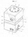
FIG. 7 is a perspective view illustrating the hydraulic oil tank according to this embodiment with hydraulic oil stored therein. -
FIGS. 8A to 8C illustrate the hydraulic oil tank according to this embodiment with the hydraulic oil stored therein, in whichFIG. 8A is a plan view,FIG. 8B is a front view, andFIG. 8C is a side view. - A hydraulic oil tank according to an embodiment of the present invention for a construction machine will hereinafter be described with reference to the drawings.
- The construction machine on which the hydraulic oil tank according to this embodiment can be mounted is, for example, a compact excavator of a type that its rear-end section stays within its undercarriage width during swinging. In the compact excavator, the installation area for various equipment is narrow, and the mounting of the hydraulic oil tank is hence liable to restrictions. As shown in
FIGS. 1 and3 , this compact excavator is provided with atravel base 1 and anupperstructure 2 mounted on thetravel base 1. On theupperstructure 2, an operator' scab 3 is arranged. Unillustrated working equipment is attached to a workingequipment connecting part 4. The unillustrated working equipment includes, for example, a boom, an arm, a bucket, and hydraulic actuators such as a boom cylinder, arm cylinder and bucket cylinder, and performs digging work or the like of earth or sand. It is to be notedthat the compact excavator is also provided with hydraulic actuators such as a travel motor for allowing thetravel base 1 to run and a swing motor for allowing theupperstructure 2 to swing. - The
hydraulic oil tank 6 according to this embodiment is made of synthetic resin, is mounted on aswing frame 2a of theupperstructure 2 as illustrated inFIGS. 4 ,5 and6 , has aside wall 6a opposing anexterior cover 5 of theupperstructure 2 with apredetermined clearance 20 therebetween, and is adapted to store hydraulic oil to be fed to the above-mentioned hydraulic actuators. - As shown in
FIGS. 1, 2 and6 , thishydraulic oil tank 6 has agage 7, which enables a visual check on alevel 8 of the hydraulic oil in thehydraulic oil tank 6 through ahole portion 5a formed in theexterior cover 5 of theupperstructure 2. - As illustrated in
FIGS. 7 and8A to 8C , thehydraulic oil tank 6 is molded, for example, in a rectangular parallelepiped as its basic external shape, and a band-shaped recessedpart 6b is formed in a central section thereof. By this recessedpart 6b, the overall strength of thehydraulic oil tank 6 made of synthetic resin is assured. As also illustrated inFIGS. 7 and8A to 8C , thehydraulic oil tank 6 has afilter 10 for conducting filtration of the hydraulic oil to maintain it in a clean state, a connection fitting 9 to which a return pipe is connected to guide return oil from the hydraulic actuators, said connection fitting 10 being arranged at the position of thefilter 10,connection fittings 11 to which drain pipes are connected, respectively, and a connection fitting 12 to which a feed pipe is connected to feed hydraulic oil to unillustrated hydraulic pumps. - As illustrated, for example, in
FIGS. 2 ,6 and7 , thegage 7 of thehydraulic oil tank 6 is installed in theside wall 6a of thehydraulic oil tank 6a, saidside wall 6a opposing theexterior cover 5, and has an internally-hollow protruding portion 7a formed protruding in a direction toward thehole portion 5a of theexterior cover 5 and awindow portion 7b comprised of a transparent member arranged at an end of the protrudingportion 7a and enabling a visual check on thelevel 8 of the hydraulic oil in thehydraulic oil tank 6. - As illustrated in
FIGS. 2 and8 , the protrudingportion 7a of thegage 7 has, for example, an outer shape of a truncated regular cone. As also illustrated inFIG. 2 , thewindow portion 7b of thegage 7 is positioned, for example, in thehole portion 5a of theexterior cover 5. - With respect to the
hydraulic oil tank 6 constructed as described above and mounted on theswing frame 2a of theupperstructure 2, visual checks are conducted during work performed over a long time by the working equipment as to whether or not the amount of the hydraulic oil stored inside, specifically the position of thelevel 8 of the hydraulic oil is within an acceptable range. These visual checks are conducted by visually seeing, from thewindow portion 7b of thegage 7 through thehole portion 5a of theexterior cover 5, the level of thelevel 8 of the hydraulic oil stored in thehydraulic oil tank 6. - According to the
hydraulic oil tank 6 of this embodiment constructed as described above, thegage 7 has the protrudingportion 7a so that a protruding part is formed on theplanar side wall 6a of thehydraulic oil tank 6. By the protruding part, strength is assured at the installation part of thegage 7. Owing to this feature, it is possible to reduce the deformation of the installation part of thegage 7, which occurs by waving of thelevel 8 of the hydraulic oil in thehydraulic oil tank 6 as caused by work or the like performed by unillustrated working equipment or by repeated up and down movements of the oil level depending on the manner of use of hydraulic actuators. According to this embodiment, the hydraulic oil in thehydraulic oil tank 6 can also be guided through the hollow protrudingportion 7a to thewindow portion 7b. - Therefore, this embodiment can assure strength at the installation part of the
gage 7, and also can bring thegage 7 close to thehole portion 5a of theexterior cover 5 while thepredetermined clearance 20 is maintainedbetween theexterior cover 5 and thehydraulic oil tank 6. Upon visually checking the position of thelevel 8 of the hydraulic oil in thehydraulic oil tank 6 from thewindow portion 7b of thegage 7 through thehole portion 5a of theexterior cover 5, this embodiment, therefore, facilitates to see theoil level 8. The check on the position of theoil level 8 can be conducted accurately, and moreover, readily, and the visibility for theoil level 8 of the hydraulic oil can be improved. - In this embodiment, the
hole portion 5a of theexterior cover 5 is filled by thewindow portion 7b of thegage 7 owing to the arrangement of thewindow portion 7b of thegage 7 in close proximity to thehole portion 5a of theexterior cover 5. Owing to this feature, it is possible to prevent rain water or the like from penetrating into theupperstructure 2 from thehole portion 5a of theexterior cover 5. Especially in this embodiment, the external shape of the protrudingportion 7a is formed in the truncated circular cone shape. As illustrated inFIG. 2 , the space in theupperstructure 2 at the position around thehole portion 5a of theexterior cover 5 can, therefore, be made smaller by the outer surface of the protrudingportion 7a. Owing to this feature, this embodiment is effective for the prevention of the penetration of rain water or the like. In this embodiment, thewindow portion 7b of thegage 7 is positioned in thehole portion 5a of theexterior cover 5. A majority of thehole portion 5a of theexterior cover 5 is, therefore, closed by thewindow portion 7b of thegage 7. This feature is also effective for the prevention of the penetration of rain water or the like. For these features, this embodiment can provide improved sealing performance for thehole portion 5a of theexterior cover 5. -
- 1
- Travel base
- 2
- Upperstructure
- 2a
- Swing frame
- 3
- Operator's cab
- 4
- Working equipment connecting part
- 5
- Exterior cover
- 5a
- Hole portion
- 6
- Hydraulic oil tank
- 6a
- Side wall
- 7
- Gage
- 7a
- Protruding portion
- 7b
- Window portion
- 8
- oil level
- 20
- Clearance
Claims (4)
- A hydraulic oil tank for a construction machine having an upperstructure provided with an exterior cover, working equipment attached to the upperstructure, and hydraulic actuators comprised of a swing motor for driving the upperstructure and an actuator for driving the working equipment,
said hydraulic oil tank being mounted on a swing frame of the upperstructure, having a side wall opposing the exterior cover of the upperstructure with a predetermined clearance therebetween, being made of synthetic resin and adapted to store hydraulic oil to be fed to the hydraulic actuators, and having a gage that enables a visual check on a level of the hydraulic oil in the hydraulic oil tank through a hole portion formed in the exterior cover, wherein :the gage is installed in the side wall of the hydraulic oil tank, and has an internally-hollow protruding portion formed protruding in a direction toward the hole portion of the exterior cover and a window portion comprised of a transparent member arranged at an end of the protruding portion and enabling the visual check on the level of the hydraulic oil in the hydraulic oil tank. - The hydraulic oil tank according to claim 1, wherein:the protruding portion of the gage has an external shape of a truncated circular cone.
- The hydraulic oil tank according to claim 2, wherein:the window portion of the gage is positioned in the hole portion of the exterior cover.
- The hydraulic oil tank according to any one of claims 1-3, wherein:the construction machine is a compact excavator of a type that a rear-end section thereof stays within an undercarriage width thereof during swinging.
Applications Claiming Priority (2)
| Application Number | Priority Date | Filing Date | Title |
|---|---|---|---|
| JP2011037356A JP5566318B2 (en) | 2011-02-23 | 2011-02-23 | Hydraulic oil tank for construction machinery |
| PCT/JP2012/053150 WO2012114913A1 (en) | 2011-02-23 | 2012-02-10 | Hydraulic oil tank for construction machine |
Publications (2)
| Publication Number | Publication Date |
|---|---|
| EP2679727A1 true EP2679727A1 (en) | 2014-01-01 |
| EP2679727A4 EP2679727A4 (en) | 2018-01-17 |
Family
ID=46720695
Family Applications (1)
| Application Number | Title | Priority Date | Filing Date |
|---|---|---|---|
| EP12749350.0A Withdrawn EP2679727A4 (en) | 2011-02-23 | 2012-02-10 | Hydraulic oil tank for construction machine |
Country Status (4)
| Country | Link |
|---|---|
| US (1) | US9062691B2 (en) |
| EP (1) | EP2679727A4 (en) |
| JP (1) | JP5566318B2 (en) |
| WO (1) | WO2012114913A1 (en) |
Cited By (2)
| Publication number | Priority date | Publication date | Assignee | Title |
|---|---|---|---|---|
| EP3428347A4 (en) * | 2016-03-07 | 2019-11-20 | Hitachi Construction Machinery Tierra Co., Ltd. | SMALL HYDRAULIC EXCAVATOR |
| CN119308363A (en) * | 2024-10-23 | 2025-01-14 | 湖南万达水电建设工程有限公司 | A river channel desilting device with anti-clogging function |
Families Citing this family (6)
| Publication number | Priority date | Publication date | Assignee | Title |
|---|---|---|---|---|
| NL2008634C2 (en) * | 2012-04-13 | 2013-10-16 | Hudson Bay Holding B V | MOBILE DEVICE. |
| JP5819891B2 (en) * | 2013-08-21 | 2015-11-24 | 日立建機株式会社 | Construction machinery |
| JP6117067B2 (en) * | 2013-09-20 | 2017-04-19 | 株式会社日立建機ティエラ | Mini excavator |
| JP6259359B2 (en) * | 2014-06-09 | 2018-01-10 | 株式会社クボタ | Hydraulic oil tank device |
| JP6320977B2 (en) * | 2015-09-16 | 2018-05-09 | 株式会社日立建機ティエラ | Small construction machinery |
| CN109989444B (en) * | 2019-05-06 | 2023-10-10 | 浙江顺得机械有限公司 | Hydraulic oil tank of excavator |
Family Cites Families (10)
| Publication number | Priority date | Publication date | Assignee | Title |
|---|---|---|---|---|
| JPH092578A (en) * | 1995-06-23 | 1997-01-07 | Yutani Heavy Ind Ltd | Construction machine tank |
| JP2002088805A (en) * | 2000-09-13 | 2002-03-27 | Hitachi Constr Mach Co Ltd | Hydraulic excavator |
| JP2005264557A (en) * | 2004-03-18 | 2005-09-29 | Shin Caterpillar Mitsubishi Ltd | Working machine |
| JP2006015845A (en) * | 2004-06-30 | 2006-01-19 | Sumitomo (Shi) Construction Machinery Manufacturing Co Ltd | Tank for construction machine |
| JP4437460B2 (en) * | 2005-05-17 | 2010-03-24 | 住友建機株式会社 | Construction machinery fuel tank |
| JP2007090953A (en) * | 2005-09-27 | 2007-04-12 | Ishikawajima Constr Mach Co | Fuel supply port and cover structure for work machine |
| FR2900090B1 (en) * | 2006-04-20 | 2010-09-10 | Inergy Automotive Systems Res | PROCESS FOR THE MANUFACTURE OF A FUEL TANK OF PLASTIC MATERIAL COMPRISING A CONNECTION WITH A SCREW |
| WO2011024928A1 (en) * | 2009-08-24 | 2011-03-03 | Kawanishi Eiji | Hybrid power generator coupled to gravity power generator using balance which has pressure load device |
| JP5481410B2 (en) * | 2011-02-18 | 2014-04-23 | 日立建機株式会社 | Liquid property identification device and liquid storage tank equipped with the device |
| JP5404680B2 (en) * | 2011-03-17 | 2014-02-05 | 日立建機株式会社 | Hydraulic oil tank mounting structure for construction machinery |
-
2011
- 2011-02-23 JP JP2011037356A patent/JP5566318B2/en not_active Expired - Fee Related
-
2012
- 2012-02-10 EP EP12749350.0A patent/EP2679727A4/en not_active Withdrawn
- 2012-02-10 WO PCT/JP2012/053150 patent/WO2012114913A1/en not_active Ceased
- 2012-02-10 US US14/001,125 patent/US9062691B2/en not_active Expired - Fee Related
Non-Patent Citations (1)
| Title |
|---|
| See references of WO2012114913A1 * |
Cited By (2)
| Publication number | Priority date | Publication date | Assignee | Title |
|---|---|---|---|---|
| EP3428347A4 (en) * | 2016-03-07 | 2019-11-20 | Hitachi Construction Machinery Tierra Co., Ltd. | SMALL HYDRAULIC EXCAVATOR |
| CN119308363A (en) * | 2024-10-23 | 2025-01-14 | 湖南万达水电建设工程有限公司 | A river channel desilting device with anti-clogging function |
Also Published As
| Publication number | Publication date |
|---|---|
| US9062691B2 (en) | 2015-06-23 |
| JP5566318B2 (en) | 2014-08-06 |
| EP2679727A4 (en) | 2018-01-17 |
| WO2012114913A1 (en) | 2012-08-30 |
| US20130327427A1 (en) | 2013-12-12 |
| JP2012172466A (en) | 2012-09-10 |
Similar Documents
| Publication | Publication Date | Title |
|---|---|---|
| US9062691B2 (en) | Hydraulic oil tank for construction machine | |
| EP2644782B1 (en) | Hydraulic hose routing for a working machine | |
| US7121185B2 (en) | Hydraulic cylinder having a snubbing valve | |
| US8920105B2 (en) | Rotation-type construction machine | |
| US20140003901A1 (en) | Hydraulic excavator | |
| US20140064824A1 (en) | Quick coupler for an earth moving machine | |
| EP2765241A1 (en) | Earth-moving apparatus for construction machinery | |
| WO2015078810A1 (en) | Traveling device and working machine | |
| JP4847974B2 (en) | Backhoe | |
| JP5258596B2 (en) | Opening and closing cover device for construction machinery | |
| US12049740B2 (en) | Bucket and work vehicle | |
| CN103485376B (en) | Engineering machinery | |
| US9670647B2 (en) | Work vehicle | |
| EP3530816A1 (en) | Hydraulic shovel | |
| US20150176247A1 (en) | Construction machine | |
| CN105637151B (en) | Hydraulic excavator | |
| US20140230587A1 (en) | Thumb Assembly | |
| US11274415B2 (en) | Bucket and work vehicle | |
| JP6056810B2 (en) | Method for manufacturing fluid pressure cylinder cover | |
| JP2006015845A (en) | Tank for construction machine | |
| JP2017160613A5 (en) | ||
| KR20150027353A (en) | Side View Camera Mounting Structure For Construction Machine | |
| KR20140038685A (en) | Fuel tank of working vehicle and manufacture method threrof | |
| KR101313276B1 (en) | Side cover mounting assembly for engine room in heavy construction machine | |
| KR20170119804A (en) | Device for guiding a piston for reciprocationg in the cylinder |
Legal Events
| Date | Code | Title | Description |
|---|---|---|---|
| PUAI | Public reference made under article 153(3) epc to a published international application that has entered the european phase |
Free format text: ORIGINAL CODE: 0009012 |
|
| 17P | Request for examination filed |
Effective date: 20130923 |
|
| AK | Designated contracting states |
Kind code of ref document: A1 Designated state(s): AL AT BE BG CH CY CZ DE DK EE ES FI FR GB GR HR HU IE IS IT LI LT LU LV MC MK MT NL NO PL PT RO RS SE SI SK SM TR |
|
| DAX | Request for extension of the european patent (deleted) | ||
| RAP1 | Party data changed (applicant data changed or rights of an application transferred) |
Owner name: HITACHI CONSTRUCTION MACHINERY TIERRA CO., LTD. |
|
| RA4 | Supplementary search report drawn up and despatched (corrected) |
Effective date: 20171220 |
|
| RIC1 | Information provided on ipc code assigned before grant |
Ipc: E02F 9/26 20060101ALI20171214BHEP Ipc: E02F 3/32 20060101ALI20171214BHEP Ipc: E02F 9/08 20060101AFI20171214BHEP |
|
| STAA | Information on the status of an ep patent application or granted ep patent |
Free format text: STATUS: REQUEST FOR EXAMINATION WAS MADE |
|
| STAA | Information on the status of an ep patent application or granted ep patent |
Free format text: STATUS: THE APPLICATION IS DEEMED TO BE WITHDRAWN |
|
| 18D | Application deemed to be withdrawn |
Effective date: 20180719 |