EP2679166A1 - Diagnosis image apparatus and operation method thereof - Google Patents
Diagnosis image apparatus and operation method thereof Download PDFInfo
- Publication number
- EP2679166A1 EP2679166A1 EP13163308.3A EP13163308A EP2679166A1 EP 2679166 A1 EP2679166 A1 EP 2679166A1 EP 13163308 A EP13163308 A EP 13163308A EP 2679166 A1 EP2679166 A1 EP 2679166A1
- Authority
- EP
- European Patent Office
- Prior art keywords
- image
- data
- heart
- contour
- subject
- Prior art date
- Legal status (The legal status is an assumption and is not a legal conclusion. Google has not performed a legal analysis and makes no representation as to the accuracy of the status listed.)
- Granted
Links
Images



Classifications
-
- A—HUMAN NECESSITIES
- A61—MEDICAL OR VETERINARY SCIENCE; HYGIENE
- A61B—DIAGNOSIS; SURGERY; IDENTIFICATION
- A61B5/00—Measuring for diagnostic purposes; Identification of persons
- A61B5/02—Detecting, measuring or recording for evaluating the cardiovascular system, e.g. pulse, heart rate, blood pressure or blood flow
-
- A—HUMAN NECESSITIES
- A61—MEDICAL OR VETERINARY SCIENCE; HYGIENE
- A61B—DIAGNOSIS; SURGERY; IDENTIFICATION
- A61B5/00—Measuring for diagnostic purposes; Identification of persons
- A61B5/0033—Features or image-related aspects of imaging apparatus, e.g. for MRI, optical tomography or impedance tomography apparatus; Arrangements of imaging apparatus in a room
- A61B5/004—Features or image-related aspects of imaging apparatus, e.g. for MRI, optical tomography or impedance tomography apparatus; Arrangements of imaging apparatus in a room adapted for image acquisition of a particular organ or body part
- A61B5/0044—Features or image-related aspects of imaging apparatus, e.g. for MRI, optical tomography or impedance tomography apparatus; Arrangements of imaging apparatus in a room adapted for image acquisition of a particular organ or body part for the heart
-
- A—HUMAN NECESSITIES
- A61—MEDICAL OR VETERINARY SCIENCE; HYGIENE
- A61B—DIAGNOSIS; SURGERY; IDENTIFICATION
- A61B8/00—Diagnosis using ultrasonic, sonic or infrasonic waves
-
- A—HUMAN NECESSITIES
- A61—MEDICAL OR VETERINARY SCIENCE; HYGIENE
- A61B—DIAGNOSIS; SURGERY; IDENTIFICATION
- A61B6/00—Apparatus or devices for radiation diagnosis; Apparatus or devices for radiation diagnosis combined with radiation therapy equipment
- A61B6/02—Arrangements for diagnosis sequentially in different planes; Stereoscopic radiation diagnosis
- A61B6/03—Computed tomography [CT]
-
- A—HUMAN NECESSITIES
- A61—MEDICAL OR VETERINARY SCIENCE; HYGIENE
- A61B—DIAGNOSIS; SURGERY; IDENTIFICATION
- A61B6/00—Apparatus or devices for radiation diagnosis; Apparatus or devices for radiation diagnosis combined with radiation therapy equipment
- A61B6/46—Arrangements for interfacing with the operator or the patient
- A61B6/461—Displaying means of special interest
- A61B6/463—Displaying means of special interest characterised by displaying multiple images or images and diagnostic data on one display
-
- A—HUMAN NECESSITIES
- A61—MEDICAL OR VETERINARY SCIENCE; HYGIENE
- A61B—DIAGNOSIS; SURGERY; IDENTIFICATION
- A61B6/00—Apparatus or devices for radiation diagnosis; Apparatus or devices for radiation diagnosis combined with radiation therapy equipment
- A61B6/50—Apparatus or devices for radiation diagnosis; Apparatus or devices for radiation diagnosis combined with radiation therapy equipment specially adapted for specific body parts; specially adapted for specific clinical applications
- A61B6/503—Apparatus or devices for radiation diagnosis; Apparatus or devices for radiation diagnosis combined with radiation therapy equipment specially adapted for specific body parts; specially adapted for specific clinical applications for diagnosis of the heart
-
- A—HUMAN NECESSITIES
- A61—MEDICAL OR VETERINARY SCIENCE; HYGIENE
- A61B—DIAGNOSIS; SURGERY; IDENTIFICATION
- A61B8/00—Diagnosis using ultrasonic, sonic or infrasonic waves
- A61B8/46—Ultrasonic, sonic or infrasonic diagnostic devices with special arrangements for interfacing with the operator or the patient
- A61B8/461—Displaying means of special interest
- A61B8/463—Displaying means of special interest characterised by displaying multiple images or images and diagnostic data on one display
-
- G—PHYSICS
- G06—COMPUTING OR CALCULATING; COUNTING
- G06T—IMAGE DATA PROCESSING OR GENERATION, IN GENERAL
- G06T7/00—Image analysis
-
- A—HUMAN NECESSITIES
- A61—MEDICAL OR VETERINARY SCIENCE; HYGIENE
- A61B—DIAGNOSIS; SURGERY; IDENTIFICATION
- A61B8/00—Diagnosis using ultrasonic, sonic or infrasonic waves
- A61B8/08—Clinical applications
- A61B8/0858—Clinical applications involving measuring tissue layers, e.g. skin, interfaces
-
- A—HUMAN NECESSITIES
- A61—MEDICAL OR VETERINARY SCIENCE; HYGIENE
- A61B—DIAGNOSIS; SURGERY; IDENTIFICATION
- A61B8/00—Diagnosis using ultrasonic, sonic or infrasonic waves
- A61B8/08—Clinical applications
- A61B8/0883—Clinical applications for diagnosis of the heart
-
- A—HUMAN NECESSITIES
- A61—MEDICAL OR VETERINARY SCIENCE; HYGIENE
- A61B—DIAGNOSIS; SURGERY; IDENTIFICATION
- A61B8/00—Diagnosis using ultrasonic, sonic or infrasonic waves
- A61B8/48—Diagnostic techniques
- A61B8/485—Diagnostic techniques involving measuring strain or elastic properties
-
- F—MECHANICAL ENGINEERING; LIGHTING; HEATING; WEAPONS; BLASTING
- F04—POSITIVE - DISPLACEMENT MACHINES FOR LIQUIDS; PUMPS FOR LIQUIDS OR ELASTIC FLUIDS
- F04C—ROTARY-PISTON, OR OSCILLATING-PISTON, POSITIVE-DISPLACEMENT MACHINES FOR LIQUIDS; ROTARY-PISTON, OR OSCILLATING-PISTON, POSITIVE-DISPLACEMENT PUMPS
- F04C2270/00—Control; Monitoring or safety arrangements
- F04C2270/04—Force
- F04C2270/041—Controlled or regulated
Definitions
- the present invention relates to a diagnosis imaging apparatus and an operation method thereof.
- Diagnosis imaging apparatuses refer to medical imaging apparatuses such as ultrasound imaging apparatuses, computed tomography (CT) apparatuses, or magnetic resonance imaging (MRI) apparatuses.
- CT computed tomography
- MRI magnetic resonance imaging
- a diagnosis imaging apparatus may acquire a first image of the heart of a subject when the subject is subjected to low intensity stress, and acquire a second image of the heart when the subject is subjected to high intensity stress.
- a user may diagnose if the subject has an illness in the heart by comparing the first image with the second image. This is because changes in cardiac muscle thickness when the subject is subjected to stress at different intensity levels depend on whether the subject has an illness in the heart or not.
- the user when the user diagnoses an illness by separately viewing the first and second images, the user may not readily perceive a difference between the first and second images during the diagnosis, which may reduce diagnosis accuracy.
- the user may need to perform an additional task, such as reconfirming the first and second images.
- the additional task may delay the diagnosis time.
- the present invention provides an efficient diagnosis imaging apparatus and an operation method thereof.
- a diagnosis imaging apparatus including: an image processing apparatus for acquiring a first image including a first contour of a heart wall based on first image data of a heart of a subject acquired when the subject is subjected to a first stress intensity level, acquiring a second image including a second contour of the heart wall based on second image data of the heart of the subject acquired when the subject is subjected to a second stress intensity level, and acquiring a third image representing a difference between the first contour and the second contour based on the first image and the second image; and a display apparatus for displaying the third image.
- an operation method of a diagnosis imaging apparatus including: acquiring a first image including a first contour of a heart wall based on first image data of a heart of a subject acquired when the subject is subjected to a first stress intensity level; acquiring a second image including a second contour of the heart wall based on second image data of the heart of the subject acquired when the subject is subjected to a second stress intensity level; acquiring a third image representing a difference between the first contour and the second contour based on the first image and the second image; and displaying the third image.
- a display apparatus displaying a third image representing a difference between a first contour and a second contour of a heart wall, the first contour of the heart wall being based on first image data of a heart of a subject acquired when the subject is subjected to a first stress intensity level, and the second contour being based on second image data of the heart of the subject acquired when the subject is subjected to a second stress intensity level.
- the term "and/or" includes any and all combinations of one or more of the associated listed items. Expressions such as “at least one of,” when preceding a list of elements, modify the entire list of elements and do not modify the individual elements of the list.
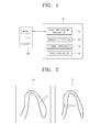
- FIG. 1 is a block diagram of a diagnosis imaging apparatus 100 according to an embodiment of the present invention.
- the diagnosis imaging apparatus 100 includes an image processing apparatus 110 and a display apparatus 120.
- the diagnosis imaging apparatus 100 may further include a storing apparatus 130 and an input apparatus 140.
- a subject 200 may be an animal body, including a human body, having a heart 210.
- the diagnosis imaging apparatus 100 is an apparatus for diagnosing whether the subject 200 has an illness in the heart 210, based on image data of the heart 210 of the subject 200.
- the diagnosis imaging apparatus 100 may be a medical imaging apparatus, such as an ultrasound imaging apparatus, a computed tomography (CT) apparatus, or magnetic resonance imaging (MRI) apparatus.
- CT computed tomography
- MRI magnetic resonance imaging
- the image processing apparatus 110 may acquire first image data of the heart 210 of the subject 200 when the subject 200 is subjected to a first stress intensity level, and may acquire second image data of the heart 210 when the subject 200 is subjected to a second stress intensity level higher than the first intensity level.
- the first image data and the second image data are obtained by subjecting the subject 200 to different stress intensity levels.
- the first image data and second image data may be 2-dimensional (2D) image data or 3-dimensional (3D) volume data, but are not limited thereto.
- the storing apparatus 130 may store the first image data and the second image data.
- the intensity level of stress may be controlled by adjusting the intensity of exercise the subject 200 does or a dose of drug administered to the subject 200.
- the first image data may be image data acquired from the subject 200 to which a first drug dosage is administered in a relaxed state
- the second image data may be image data acquired from the subject 200 to which a second drug dosage higher than the first drug dosage is administered in a relaxed state.
- the drug administered to the subject 100 may be dobutamine.
- the first image data may be image data acquired while the subject 200 is exercising at a first exercise intensity level
- the second image data may be image data acquired while the subject 200 is exercising at a second intensity level higher than the first exercise intensity level.
- the exercise at the first intensity level may be riding a bike
- the exercise at the second intensity level may be walking or running.
- the image processing apparatus 110 may acquire a first image including a first contour of the heart wall of the heart 210 based on the first image data, and acquire a second image including a second contour of the heart wall of the heart 210 based on the second image data.
- FIG. 2 illustrates a first image 10 and a second image 20 acquired by the image processing apparatus 110 of FIG. 1 , according to an embodiment of the present invention.
- the first image 10 may include a first contour 11 of the heart wall of the heart 210 when the subject 200 is subjected to a first stress intensity level.
- the second image 21 may include a second contour 21 of the heart wall of the heart 210 when the subject 200 is subjected to a second stress intensity level higher than the first stress intensity level.
- the first image 10 may be an image including the first contour 11 of the heart wall based on a cross-sectional image of the heart 210 acquired from the first image data
- the second image 20 may be an image including the second contour 21 of the heart wall based on a cross-sectional image of the heart 210 acquired from the second image data.
- the cross-sectional image of the heart 210 may be a 4-chamber view, a 3-chamber view, or a 2-chamber view.
- Each of the first contour 11 and the second contour 21 may represent the heart wall of the left ventricle.
- first image 10 and the second image 20 are illustrated as only including the first contour 11 and the second contour 21, respectively, the embodiment is not limited thereto. In some other embodiments, the first image 10 and the second image 20 may be images with the first contour 11 and the second contour 21 on cross-sections of the heart, respectively.
- the first contour 11 and the second contour 21 may be automatically or manually drawn on the first image 10 and the second image 20, respectively.
- the first contour 11 and the second contour 21 may be automatically drawn based on brightness.
- the first contour 11 and the second contour 21 may be drawn based on a user input via the input apparatus 140.
- the input apparatus 140 may be, for example, a touch panel on the display apparatus 120.
- a user may draw contours of the heart wall on a displayed cross-sectional image of the heart by using the input apparatus 140, so that the first contour 11 and the second contour 21 may be included in the first image and the second image 20, respectively.
- the image processing apparatus 110 may acquire a third image representing a difference between the first contour 11 and the second contour 21 based on the first image 10 and the second image 20.
- the display apparatus 120 may display the third image.
- FIG. 3 illustrates a third image 30 displayed on the display apparatus 120 of FIG. 1 , according to another embodiment of the present invention.
- the first image 10 including the first contour 11 and the second image 20 including the second contour 21 are overlapped on the third image 30 so that a difference between the first contour 11 and the second contour 21 is represented on the third image 30.
- the first contour 11 and the second contour 12 in the third image 30 may be represented by, for example, a solid line and a dashed line, respectively, to be distinguished from each other.
- the first contour 11 and the second contour 21 may be represented in different colors to be distinguished from each other.
- the third image 30 may represent the difference between the first contour 11 and the second contour 21 in any of a variety of ways, and thus, the third image 30 is not limited to the above.
- the user may easily perceive the difference between the first contour 11 and the second contour 21 on the first image 30.
- FIG. 4 illustrates a third image 30a displayed on the display apparatus 120 of FIG. 1 , according to another embodiment of the present invention.
- the first image 10 including the first contour 11 and the second image 20 including the second contour 21 are overlapped on the third image 30 so that a difference between the first contour 11 and the second contour 21 is represented on the third image 30a.
- a non-overlapping heart wall area between the first contour 11 and the second contour 21 in the third image 30a i.e., a gap area GA
- the gap area GA in the third image 30a may be represented hatched or in a different color to be distinguished from the other areas. Therefore, the user may easily perceive the difference between the first contour 11 and the second contour 21 on the third image 30a.
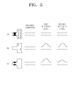
- FIG. 5 is a view illustrating changes in thickness of a cardiac muscle according to types of heart conditions and stress levels.
- (A) to (C) in FIG. 5 illustrate different types of heart conditions of a subject observed to have changes in thickness of the cardiac muscle when the subject is in a relaxed state, is subjected to a first stress intensity level, or is subjected to a second intensity stress level.
- whether the heart has an illness such as cardiac muscle damage, contraction of the heart coronary arteries, or like, may be diagnosed by comparing changes in thickness of the cardiac muscle after subjecting the subject to stress at different intensity levels.
- the user may intuitively perceive the difference in heart wall thickness of the subject on the third image 30 that represents the difference between the first contour 11 and the second contour 21 displayed on the display apparatus 120. Therefore, the user may be convenienced in diagnosing the heart 210 of the subject 200, and a diagnosis speed may be improved. Since the third image 30 represents the difference between the first contour 11 and the second contour 21, this may ensure an objective comparison between the thicknesses of the heart wall when the subject 200 is subjected to stress at different intensity levels, and diagnosis accuracy may be increased.
- diagnosis accuracy may be reduced.
- an additional task that, for example, the user reconfirms the first image 10 and/or the second image 20 may be performed. However, such an additional task may delay the diagnosis time.
- the diagnosis imaging apparatus 100 may provide user convenience to diagnose and may improve the diagnosis speed.
- the display apparatus 120 may also display the first image 10 and the second image 20 along with the third image 30.
- FIG. 6 illustrates first to third images 10c to 30c displayed on the display apparatus 120 of FIG. 1 , according to another embodiment of the present invention.
- the display apparatus 120 may display the first image 10c and the second image 20c along with the third image 30c.
- the user may intuitively perceive a difference in thickness of the heart wall between when the subject is subjected to a first stress intensity level and when the subject is subjected to a second stress intensity level on the first to third images 10c to 30c.
- the first image 10c and the second image 20c may further include a first marker 12 and a second marker 22, respectively, representing stress intensity levels the subject is subjected to, in addition to the first contour 11 c and the second contour 21 c.
- the first marker 12 and the second marker 22 may display the stress intensity level the subject is subjected to as at least one of an image and text.
- the first marker 12 may represent the first stress intensity level by displaying an image of administration of a low drug dosage
- the second marker 22 may represent the second stress intensity level higher than the first intensity level, by displaying an image of administration of a large drug dosage.
- the user may readily perceive the first image 10c corresponding to the first stress intensity level and the second image 20c corresponding to the second stress intensity level from the first marker 12 and the second marker 22.
- FIG. 7 illustrates first to third images 10d to 30d displayed on the display apparatus 120 of FIG. 1 .
- the first image 10d and the second image 20d may include a first marker 12a and a second marker 22a, respectively, representing stress intensity levelsthe subject is subjected to.
- the first marker 12a may represent the first stress intensity level by displaying an image of riding a bike
- the second marker 22a may represent the second stress intensity level, higher than the first intensity level, by displaying an image of walking or running.
- the first markers 12 and 12a and the second markers 22 and 22a in FIGS. 6 and 7 are only for illustrative purposes, not for limiting the embodiments thereof.
- the first markers 12 and 12a and the second markers 22 and 22a may display the stress intensity level the subject is subjected to in a variety of manners.
- the image processing apparatus 110 may acquire first data of the heart 210 of the subject 200 based on the first image data of the subject 200 acquired when the subject 200 is subjected to a first stress intensity level, and may acquire second data of the heart 210 based on the second image data acquired when the subject 200 is subjected to a second stress intensity level higher than the first stress intensity level.
- the image processing apparatus 110 may acquire a fourth image representing a difference between the first data and the second data.
- the display apparatus 120 may display the fourth image along with the first to third images 10 to 30.
- the first data and the second data may be used to evaluate the functions of the heart 210.
- the first data and the second data may be heart strain, a strain rate as strain with respect to time obtained by dividing strain by time, a heart wall thickness, a cardiac muscle change rate, or a heart volume, etc.
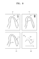
- FIG. 8 illustrates first to fourth images 10e to 40e displayed on the display apparatus 120 of FIG. 1 , according to another embodiment of the present invention.
- the display apparatus 120 may display the fourth image 40e along with the first to third images 10e to 30e.
- the above-descriptions of the first to third images may be referred to herein to avoid redundancy.
- the fourth image 40e may include a graph of first data DTA1 and second data DTA2 with respect to time t, wherein the time t may be a frame.
- the user may more easily analyze a difference between the first image 10e and the second image 20e from the fourth image 40e.
- the fourth image 40e illustrates one piece of first data DAT1 and one piece of second data DTA2
- the fourth image 40e may display a plurality of pieces of first data DAT1 and a plurality of pieces of second data DAT2.
- the first image 10e and the second image 20e may be represented with a plurality of pieces of first data DTA1 and a plurality of pieces of second data DTA2 that are assigned to a plurality of segments of the heart, respectively, as data for evaluating functions of the heart.
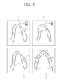
- FIG. 9 illustrates first to fourth images 10f to 40f displayed on the display apparatus 120 of FIG. 1 , according to another embodiment of the present invention.
- the fourth image 40f may represent a plurality of segments W1-W6 of the heart, each with a quantitative difference between the first data and the second data.
- the first data and the second data may be heart wall thicknesses.
- the second segment W2 has a difference of about 3% between a heart wall thickness corresponding to the stress at the first intensity level and a heart wall thickness corresponding to the stress at the second intensity level higher than the first intensity level.
- a fourth image representing a difference between the first data corresponding to the first intensity level of stress and the second data corresponding to the second intensity level of stress may be displayed in any of a variety of manners depending on the types of the first and second data to evaluate functions of the heart.
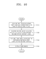
- FIG. 10 is a flowchart of an operation method of a diagnosis imaging apparatus, according to an embodiment of the present invention.
- the diagnosis imaging apparatus may acquire a first image including a first contour of the heart wall based on first image data of the heart of the subject acquired when the subject is subjected to stress at a first intensity level (Operation S110).
- the diagnosis imaging apparatus may acquire a second image including a second contour of the heart wall based on second image data of the heart of the subject acquired when the subject is subjected to at a second stress intensity level higher than the first stress intensity level (Operation S120).
- the diagnosis imaging apparatus may acquire a third image representing a difference between the first contour and the second contour based on the first image and the second image (Operation S130).
- the diagnosis imaging apparatus may display the third image (Operation S140).
- the operation method of FIG. 10 may be performed by the diagnosis imaging apparatus 100 of FIG. 1 .
- the relevant descriptions described above with reference to FIGS. 1 to 9 may be referred to as a description of each operation of the method.
- diagnosis imaging apparatuses and operating methods thereof are efficient.
- the embodiments of the method described above may be written as computer programs and can be implemented in general-use digital computers that execute the programs using a computer-readable recording medium.
- Data used in the above-described embodiments can be recorded on a medium in various means.
- the computer-readable recording medium include magnetic storage media (e.g., ROM, RAM, USB, floppy disks, hard disks, etc.), optical recording media (e.g., CD-ROMs, or DVDs), and peripheral component interfaces (PCI) (e.g., PCI-express, or Wifi).
- PCI peripheral component interfaces
Landscapes
- Health & Medical Sciences (AREA)
- Life Sciences & Earth Sciences (AREA)
- Engineering & Computer Science (AREA)
- Medical Informatics (AREA)
- Physics & Mathematics (AREA)
- Nuclear Medicine, Radiotherapy & Molecular Imaging (AREA)
- Radiology & Medical Imaging (AREA)
- General Health & Medical Sciences (AREA)
- Molecular Biology (AREA)
- Veterinary Medicine (AREA)
- Biophysics (AREA)
- Pathology (AREA)
- Biomedical Technology (AREA)
- Heart & Thoracic Surgery (AREA)
- Public Health (AREA)
- Animal Behavior & Ethology (AREA)
- Surgery (AREA)
- Cardiology (AREA)
- Optics & Photonics (AREA)
- High Energy & Nuclear Physics (AREA)
- Oral & Maxillofacial Surgery (AREA)
- Dentistry (AREA)
- Human Computer Interaction (AREA)
- Physiology (AREA)
- General Physics & Mathematics (AREA)
- Theoretical Computer Science (AREA)
- Apparatus For Radiation Diagnosis (AREA)
- Magnetic Resonance Imaging Apparatus (AREA)
- Computer Vision & Pattern Recognition (AREA)
- Measuring And Recording Apparatus For Diagnosis (AREA)
Abstract
Description
- This application claims the benefit of Korean Patent Application No.
10-2012-0070231, filed on June 28, 2012 - The present invention relates to a diagnosis imaging apparatus and an operation method thereof.
- Diagnosis imaging apparatuses refer to medical imaging apparatuses such as ultrasound imaging apparatuses, computed tomography (CT) apparatuses, or magnetic resonance imaging (MRI) apparatuses.
- A diagnosis imaging apparatus may acquire a first image of the heart of a subject when the subject is subjected to low intensity stress, and acquire a second image of the heart when the subject is subjected to high intensity stress. A user may diagnose if the subject has an illness in the heart by comparing the first image with the second image. This is because changes in cardiac muscle thickness when the subject is subjected to stress at different intensity levels depend on whether the subject has an illness in the heart or not.
- However, when the user diagnoses an illness by separately viewing the first and second images, the user may not readily perceive a difference between the first and second images during the diagnosis, which may reduce diagnosis accuracy. To increase the diagnosis accuracy, the user may need to perform an additional task, such as reconfirming the first and second images. However, the additional task may delay the diagnosis time.
- Therefore, there is a demand for an efficient diagnosis imaging apparatus and an operation method thereof.
- The present invention provides an efficient diagnosis imaging apparatus and an operation method thereof.
- According to an aspect of the present invention, there is provided a diagnosis imaging apparatus including: an image processing apparatus for acquiring a first image including a first contour of a heart wall based on first image data of a heart of a subject acquired when the subject is subjected to a first stress intensity level, acquiring a second image including a second contour of the heart wall based on second image data of the heart of the subject acquired when the subject is subjected to a second stress intensity level, and acquiring a third image representing a difference between the first contour and the second contour based on the first image and the second image; and a display apparatus for displaying the third image.
- According to another aspect of the present invention, there is provided an operation method of a diagnosis imaging apparatus, the method including: acquiring a first image including a first contour of a heart wall based on first image data of a heart of a subject acquired when the subject is subjected to a first stress intensity level; acquiring a second image including a second contour of the heart wall based on second image data of the heart of the subject acquired when the subject is subjected to a second stress intensity level; acquiring a third image representing a difference between the first contour and the second contour based on the first image and the second image; and displaying the third image.
- According to another aspect of the present invention, there is provided a display apparatus displaying a third image representing a difference between a first contour and a second contour of a heart wall, the first contour of the heart wall being based on first image data of a heart of a subject acquired when the subject is subjected to a first stress intensity level, and the second contour being based on second image data of the heart of the subject acquired when the subject is subjected to a second stress intensity level.
- The above and other features and advantages of the present invention will become more apparent by describing in detail exemplary embodiments thereof with reference to the attached drawings in which:
-
FIG. 1 is a block diagram of a diagnosis imaging apparatus according to an embodiment of the present invention; -
FIG. 2 illustrates a first image and a second image acquired by an image processing apparatus ofFIG. 1 , according to an embodiment of the present invention; -
FIG. 3 illustrates a third image displayed on a display apparatus ofFIG. 1 , according to an embodiment of the present invention; -
FIG. 4 illustrates a third image displayed on the display apparatus ofFIG. 1 , according to another embodiment of the present invention; -
FIG. 5 is a view illustrating changes in thickness of a cardiac muscle according to types of heart conditions and stress levels; -
FIG. 6 illustrates first to third images displayed on the display apparatus ofFIG. 1 , according to another embodiment of the present invention; -
FIG. 7 illustrates first to third images displayed on the display apparatus ofFIG. 1 , according to another embodiment of the present invention; -
FIG. 8 illustrates first to fourth images displayed on the display apparatus ofFIG. 1 , according to another embodiment of the present invention; -
FIG. 9 illustrates first to third images displayed on the display apparatus ofFIG. 1 , according to another embodiment of the present invention; and -
FIG. 10 is a flowchart of an operation method of a diagnosis imaging apparatus, according to an embodiment of the present invention. - As used herein, the term "and/or" includes any and all combinations of one or more of the associated listed items. Expressions such as "at least one of," when preceding a list of elements, modify the entire list of elements and do not modify the individual elements of the list.
- Hereinafter, embodiments of the present invention are described in detail with reference to the appended drawings.
-
FIG. 1 is a block diagram of adiagnosis imaging apparatus 100 according to an embodiment of the present invention. - Referring to
FIG. 1 , thediagnosis imaging apparatus 100 includes animage processing apparatus 110 and adisplay apparatus 120. Thediagnosis imaging apparatus 100 may further include astoring apparatus 130 and aninput apparatus 140. Asubject 200 may be an animal body, including a human body, having aheart 210. - The
diagnosis imaging apparatus 100 is an apparatus for diagnosing whether thesubject 200 has an illness in theheart 210, based on image data of theheart 210 of thesubject 200. In some embodiments, thediagnosis imaging apparatus 100 may be a medical imaging apparatus, such as an ultrasound imaging apparatus, a computed tomography (CT) apparatus, or magnetic resonance imaging (MRI) apparatus. - The
image processing apparatus 110 may acquire first image data of theheart 210 of thesubject 200 when thesubject 200 is subjected to a first stress intensity level, and may acquire second image data of theheart 210 when thesubject 200 is subjected to a second stress intensity level higher than the first intensity level. The first image data and the second image data are obtained by subjecting thesubject 200 to different stress intensity levels. The first image data and second image data may be 2-dimensional (2D) image data or 3-dimensional (3D) volume data, but are not limited thereto. Thestoring apparatus 130 may store the first image data and the second image data. - The intensity level of stress may be controlled by adjusting the intensity of exercise the
subject 200 does or a dose of drug administered to thesubject 200. For example, the first image data may be image data acquired from thesubject 200 to which a first drug dosage is administered in a relaxed state, and the second image data may be image data acquired from thesubject 200 to which a second drug dosage higher than the first drug dosage is administered in a relaxed state. The drug administered to thesubject 100 may be dobutamine. In some other embodiments, the first image data may be image data acquired while thesubject 200 is exercising at a first exercise intensity level, and the second image data may be image data acquired while thesubject 200 is exercising at a second intensity level higher than the first exercise intensity level. For example, the exercise at the first intensity level may be riding a bike, and the exercise at the second intensity level may be walking or running. - The
image processing apparatus 110 may acquire a first image including a first contour of the heart wall of theheart 210 based on the first image data, and acquire a second image including a second contour of the heart wall of theheart 210 based on the second image data. -
FIG. 2 illustrates afirst image 10 and asecond image 20 acquired by theimage processing apparatus 110 ofFIG. 1 , according to an embodiment of the present invention. - Referring to
FIGS. 1 and 2 , thefirst image 10 may include afirst contour 11 of the heart wall of theheart 210 when thesubject 200 is subjected to a first stress intensity level. Thesecond image 21 may include asecond contour 21 of the heart wall of theheart 210 when thesubject 200 is subjected to a second stress intensity level higher than the first stress intensity level. - The
first image 10 may be an image including thefirst contour 11 of the heart wall based on a cross-sectional image of theheart 210 acquired from the first image data, and thesecond image 20 may be an image including thesecond contour 21 of the heart wall based on a cross-sectional image of theheart 210 acquired from the second image data. The cross-sectional image of theheart 210 may be a 4-chamber view, a 3-chamber view, or a 2-chamber view. Each of thefirst contour 11 and thesecond contour 21 may represent the heart wall of the left ventricle. - Although in
FIG. 2 thefirst image 10 and thesecond image 20 are illustrated as only including thefirst contour 11 and thesecond contour 21, respectively, the embodiment is not limited thereto. In some other embodiments, thefirst image 10 and thesecond image 20 may be images with thefirst contour 11 and thesecond contour 21 on cross-sections of the heart, respectively. - The
first contour 11 and thesecond contour 21 may be automatically or manually drawn on thefirst image 10 and thesecond image 20, respectively. For example, thefirst contour 11 and thesecond contour 21 may be automatically drawn based on brightness. In some other embodiments, thefirst contour 11 and thesecond contour 21 may be drawn based on a user input via theinput apparatus 140. Theinput apparatus 140 may be, for example, a touch panel on thedisplay apparatus 120. A user may draw contours of the heart wall on a displayed cross-sectional image of the heart by using theinput apparatus 140, so that thefirst contour 11 and thesecond contour 21 may be included in the first image and thesecond image 20, respectively. - The
image processing apparatus 110 may acquire a third image representing a difference between thefirst contour 11 and thesecond contour 21 based on thefirst image 10 and thesecond image 20. Thedisplay apparatus 120 may display the third image. -
FIG. 3 illustrates athird image 30 displayed on thedisplay apparatus 120 ofFIG. 1 , according to another embodiment of the present invention. - Referring to
FIGS. 2 and3 , thefirst image 10 including thefirst contour 11 and thesecond image 20 including thesecond contour 21 are overlapped on thethird image 30 so that a difference between thefirst contour 11 and thesecond contour 21 is represented on thethird image 30. Thefirst contour 11 and thesecond contour 12 in thethird image 30 may be represented by, for example, a solid line and a dashed line, respectively, to be distinguished from each other. - Unlike in
FIG. 3 , thefirst contour 11 and thesecond contour 21 may be represented in different colors to be distinguished from each other. Thethird image 30 may represent the difference between thefirst contour 11 and thesecond contour 21 in any of a variety of ways, and thus, thethird image 30 is not limited to the above. - Therefore, the user may easily perceive the difference between the
first contour 11 and thesecond contour 21 on thefirst image 30. -
FIG. 4 illustrates athird image 30a displayed on thedisplay apparatus 120 ofFIG. 1 , according to another embodiment of the present invention. - Referring to
FIGS. 2 and4 , thefirst image 10 including thefirst contour 11 and thesecond image 20 including thesecond contour 21 are overlapped on thethird image 30 so that a difference between thefirst contour 11 and thesecond contour 21 is represented on thethird image 30a. A non-overlapping heart wall area between thefirst contour 11 and thesecond contour 21 in thethird image 30a, i.e., a gap area GA, may be displayed to be distinguished from other areas. In some embodiments, the gap area GA in thethird image 30a may be represented hatched or in a different color to be distinguished from the other areas. Therefore, the user may easily perceive the difference between thefirst contour 11 and thesecond contour 21 on thethird image 30a. -
FIG. 5 is a view illustrating changes in thickness of a cardiac muscle according to types of heart conditions and stress levels. In particular, (A) to (C) inFIG. 5 illustrate different types of heart conditions of a subject observed to have changes in thickness of the cardiac muscle when the subject is in a relaxed state, is subjected to a first stress intensity level, or is subjected to a second intensity stress level. - (A) in
FIG. 5 illustrates a heart condition with involving contraction of the coronary arteries of the subject and severe cardiac muscle damage. In this case, no change in thickness of the cardiac muscle was found in a relaxed state or when the subject is subjected to the first stress intensity level or the second stress intensity level. - (B) in
FIG. 5 illustrates a heart condition with no contraction of the heart coronary arteries of the subject and nearly zero cardiac muscle damage. The thickness of the cardiac muscle increased when the subject is subjected to the first intensity stress level or the second stress intensity level higher than the first intensity stress level, as compared with the thickness of the cardiac muscle in a relaxed state. - (C) in
FIG. 5 illustrates a heart condition with contraction of the coronary arteries of the subject and no cardiac muscle damage. The thickness of the cardiac muscle increased when the subject is subjected to the first stress intensity level or the second stress intensity level higher than the first stress intensity level, as compared with the thickness of the cardiac muscle in a relaxed state, with a greater increase in thickness of the cardiac muscle when the first stress intensity level lower than the second stress intensity level is applied, as compared with when the second stress intensity level is applied. - Therefore, whether the heart has an illness, such as cardiac muscle damage, contraction of the heart coronary arteries, or like, may be diagnosed by comparing changes in thickness of the cardiac muscle after subjecting the subject to stress at different intensity levels.
- Referring back to
FIGS. 1 to 3 , the user may intuitively perceive the difference in heart wall thickness of the subject on thethird image 30 that represents the difference between thefirst contour 11 and thesecond contour 21 displayed on thedisplay apparatus 120. Therefore, the user may be convenienced in diagnosing theheart 210 of the subject 200, and a diagnosis speed may be improved. Since thethird image 30 represents the difference between thefirst contour 11 and thesecond contour 21, this may ensure an objective comparison between the thicknesses of the heart wall when the subject 200 is subjected to stress at different intensity levels, and diagnosis accuracy may be increased. - If only the
first image 10 and/or thesecond image 20, excluding thethird image 30, are displayed on thedisplay apparatus 120, the user may not be able to readily perceive a difference in heart wall thickness when the subject 200 is subjected to stress at different intensity levels. Thus, diagnosis accuracy may be reduced. To increase diagnosis accuracy, an additional task that, for example, the user reconfirms thefirst image 10 and/or thesecond image 20 may be performed. However, such an additional task may delay the diagnosis time. - Therefore, according to the above embodiments of the present invention, the
diagnosis imaging apparatus 100 may provide user convenience to diagnose and may improve the diagnosis speed. - The
display apparatus 120 may also display thefirst image 10 and thesecond image 20 along with thethird image 30. -
FIG. 6 illustrates first tothird images 10c to 30c displayed on thedisplay apparatus 120 ofFIG. 1 , according to another embodiment of the present invention. - Referring to
FIG. 6 , the display apparatus 120 (FIG. 1 ) may display thefirst image 10c and thesecond image 20c along with thethird image 30c. The user may intuitively perceive a difference in thickness of the heart wall between when the subject is subjected to a first stress intensity level and when the subject is subjected to a second stress intensity level on the first tothird images 10c to 30c. - The
first image 10c and thesecond image 20c may further include afirst marker 12 and asecond marker 22, respectively, representing stress intensity levels the subject is subjected to, in addition to thefirst contour 11 c and thesecond contour 21 c. Thefirst marker 12 and thesecond marker 22 may display the stress intensity level the subject is subjected to as at least one of an image and text. As illustrated inFIG. 6 , thefirst marker 12 may represent the first stress intensity level by displaying an image of administration of a low drug dosage, and thesecond marker 22 may represent the second stress intensity level higher than the first intensity level, by displaying an image of administration of a large drug dosage. - The user may readily perceive the
first image 10c corresponding to the first stress intensity level and thesecond image 20c corresponding to the second stress intensity level from thefirst marker 12 and thesecond marker 22. -
FIG. 7 illustrates first tothird images 10d to 30d displayed on thedisplay apparatus 120 ofFIG. 1 . - Referring to
FIG. 7 , thefirst image 10d and thesecond image 20d may include afirst marker 12a and asecond marker 22a, respectively, representing stress intensity levelsthe subject is subjected to. Thefirst marker 12a may represent the first stress intensity level by displaying an image of riding a bike, and thesecond marker 22a may represent the second stress intensity level, higher than the first intensity level, by displaying an image of walking or running. - The
first markers second markers FIGS. 6 and7 are only for illustrative purposes, not for limiting the embodiments thereof. Thefirst markers second markers - Referring back to
FIGS. 1 and3 , theimage processing apparatus 110 may acquire first data of theheart 210 of the subject 200 based on the first image data of the subject 200 acquired when the subject 200 is subjected to a first stress intensity level, and may acquire second data of theheart 210 based on the second image data acquired when the subject 200 is subjected to a second stress intensity level higher than the first stress intensity level. Theimage processing apparatus 110 may acquire a fourth image representing a difference between the first data and the second data. Thedisplay apparatus 120 may display the fourth image along with the first tothird images 10 to 30. - The first data and the second data may be used to evaluate the functions of the
heart 210. For example, the first data and the second data may be heart strain, a strain rate as strain with respect to time obtained by dividing strain by time, a heart wall thickness, a cardiac muscle change rate, or a heart volume, etc. -
FIG. 8 illustrates first tofourth images 10e to 40e displayed on thedisplay apparatus 120 ofFIG. 1 , according to another embodiment of the present invention. - Referring to
FIG. 8 , the display apparatus 120 (seeFIG. 1 ) may display thefourth image 40e along with the first tothird images 10e to 30e. The above-descriptions of the first to third images may be referred to herein to avoid redundancy. - The
fourth image 40e may include a graph of first data DTA1 and second data DTA2 with respect to time t, wherein the time t may be a frame. The user may more easily analyze a difference between thefirst image 10e and thesecond image 20e from thefourth image 40e. - Although in
FIG. 8 thefourth image 40e illustrates one piece of first data DAT1 and one piece of second data DTA2, thefourth image 40e may display a plurality of pieces of first data DAT1 and a plurality of pieces of second data DAT2. Thefirst image 10e and thesecond image 20e may be represented with a plurality of pieces of first data DTA1 and a plurality of pieces of second data DTA2 that are assigned to a plurality of segments of the heart, respectively, as data for evaluating functions of the heart. -
FIG. 9 illustrates first tofourth images 10f to 40f displayed on thedisplay apparatus 120 ofFIG. 1 , according to another embodiment of the present invention. - Referring to
FIG. 9 , thefourth image 40f may represent a plurality of segments W1-W6 of the heart, each with a quantitative difference between the first data and the second data. InFIG. 9 , the first data and the second data may be heart wall thicknesses. For example, the second segment W2 has a difference of about 3% between a heart wall thickness corresponding to the stress at the first intensity level and a heart wall thickness corresponding to the stress at the second intensity level higher than the first intensity level. - Further to the embodiments of
FIGS. 8 and9 , a fourth image representing a difference between the first data corresponding to the first intensity level of stress and the second data corresponding to the second intensity level of stress may be displayed in any of a variety of manners depending on the types of the first and second data to evaluate functions of the heart. -
FIG. 10 is a flowchart of an operation method of a diagnosis imaging apparatus, according to an embodiment of the present invention. - Referring to
FIG. 10 , the diagnosis imaging apparatus may acquire a first image including a first contour of the heart wall based on first image data of the heart of the subject acquired when the subject is subjected to stress at a first intensity level (Operation S110). The diagnosis imaging apparatus may acquire a second image including a second contour of the heart wall based on second image data of the heart of the subject acquired when the subject is subjected to at a second stress intensity level higher than the first stress intensity level (Operation S120). The diagnosis imaging apparatus may acquire a third image representing a difference between the first contour and the second contour based on the first image and the second image (Operation S130). The diagnosis imaging apparatus may display the third image (Operation S140). - The operation method of
FIG. 10 may be performed by thediagnosis imaging apparatus 100 ofFIG. 1 . The relevant descriptions described above with reference toFIGS. 1 to 9 may be referred to as a description of each operation of the method. - According to the embodiments described above, diagnosis imaging apparatuses and operating methods thereof are efficient.
- The embodiments of the method described above may be written as computer programs and can be implemented in general-use digital computers that execute the programs using a computer-readable recording medium. Data used in the above-described embodiments can be recorded on a medium in various means. Examples of the computer-readable recording medium include magnetic storage media (e.g., ROM, RAM, USB, floppy disks, hard disks, etc.), optical recording media (e.g., CD-ROMs, or DVDs), and peripheral component interfaces (PCI) (e.g., PCI-express, or Wifi).
- While the present invention has been particularly shown and described with reference to exemplary embodiments thereof, it will be understood by those of ordinary skill in the art that various changes in form and details may be made therein without departing from the spirit and scope of the present invention as defined by the following claims.
Claims (15)
- A diagnosis imaging apparatus comprising:an image processing apparatus for acquiring a first image including a first contour of a heart wall based on first image data of a heart of a subject acquired when the subject is subjected to a first stress intensity level, acquiring a second image including a second contour of the heart wall based on second image data of the heart of the subject acquired when the subject is subjected to a second stress intensity level, and acquiring a third image representing a difference between the first contour and the second contour based on the first image and the second image; anda display apparatus for displaying the third image.
- The diagnosis imaging apparatus of claim 1, wherein the third image represents the overlapping of the first contour with the second contour.
- The diagnosis imaging apparatus of claim 2, wherein the display apparatus displays the first image and the second image along with the third image.
- The diagnosis imaging apparatus of claim 2, wherein the first image and the second image each further comprise a marker indicating a stress intensity level the subject is subjected to.
- The diagnosis imaging apparatus of claim 2, wherein the image processing apparatus acquires first data of the heart based on the first image data, second data of the heart based on the second image data, and a fourth image representing a difference between the first data and the second data; and the display apparatus displays the fourth image along with the first to third images.
- The diagnosis imaging apparatus of claim 5, wherein the first data and the second data each include at least one of heart strain, a strain rate, a heart wall thickness, a cardiac muscle change rate, and a heart volume.
- The diagnosis imaging apparatus of claim 6, wherein the fourth image includes a graph of the first data and the second data with respect to time.
- The diagnosis imaging apparatus of claim 6, wherein the first data and the second data each has a plurality of pieces of data corresponding to a plurality of segments of the hearts.
- The diagnosis imaging apparatus of claim 8, wherein the first image represents the plurality of segments of the heart each with a quantitative difference between the first data and the second data.
- The diagnosis imaging apparatus of claim 1, wherein the stress at the first intensity level and the stress at the second intensity level are applied by administering different drug dosages to the subject, or by the subject exercising at different intensity levels.
- An operation method of a diagnosis imaging apparatus, the method comprising:acquiring a first image including a first contour of a heart wall based on first image data of a heart of a subject acquired when the subject is subjected to a first stress intensity level;acquiring a second image including a second contour of the heart wall based on second image data of the heart of the subject acquired when the subject is subjected to a second stress intensity level;acquiring a third image representing a difference between the first contour and the second contour based on the first image and the second image; anddisplaying the third image.
- The operation method of claim 11, further comprising:acquiring first data of the heart based on the first image data;acquiring second data of the heart based on the second image data;acquiring a fourth image representing a difference between the first data and the second data; anddisplaying the fourth image along with the third image.
- The operation method of claim 12, wherein the first data and the second data each include at least one of heart strain, a strain rate, a heart wall thickness, a cardiac muscle change rate, and a heart volume.
- A computer-readable recording medium having embodied thereon a program for executing the operation method of a diagnosis imaging apparatus according to any one of claims 11 to 13.
- A display apparatus displaying a third image representing a difference between a first contour and a second contour of a heart wall, the first contour of the heart wall being based on first image data of a heart of a subject acquired when the subject is subjected to a first stress intensity level, and the second contour being based on second image data of the heart of the subject acquired when the subject is subjected to a second stress intensity level.
Applications Claiming Priority (1)
| Application Number | Priority Date | Filing Date | Title |
|---|---|---|---|
| KR1020120070231A KR20140002997A (en) | 2012-06-28 | 2012-06-28 | Diagnosis image apparatus and operating method thereof |
Publications (2)
| Publication Number | Publication Date |
|---|---|
| EP2679166A1 true EP2679166A1 (en) | 2014-01-01 |
| EP2679166B1 EP2679166B1 (en) | 2016-03-30 |
Family
ID=48143451
Family Applications (1)
| Application Number | Title | Priority Date | Filing Date |
|---|---|---|---|
| EP13163308.3A Active EP2679166B1 (en) | 2012-06-28 | 2013-04-11 | Diagnosis image apparatus and operation method thereof |
Country Status (3)
| Country | Link |
|---|---|
| US (1) | US20140005516A1 (en) |
| EP (1) | EP2679166B1 (en) |
| KR (1) | KR20140002997A (en) |
Families Citing this family (1)
| Publication number | Priority date | Publication date | Assignee | Title |
|---|---|---|---|---|
| CN114886371B (en) * | 2022-05-07 | 2025-08-22 | 合肥学院 | Crohn's disease diagnosis auxiliary system based on flexible endoscope |
Citations (5)
| Publication number | Priority date | Publication date | Assignee | Title |
|---|---|---|---|---|
| WO1999049775A2 (en) * | 1998-03-30 | 1999-10-07 | Echovision, Inc. | Echocardiography workstation |
| WO2001016886A2 (en) * | 1999-08-27 | 2001-03-08 | Isis Innovation Limited | Non-rigid motion image analysis |
| JP2005218713A (en) * | 2004-02-06 | 2005-08-18 | Aloka Co Ltd | Ultrasonic diagnostic system |
| US20060058610A1 (en) * | 2004-08-31 | 2006-03-16 | General Electric Company | Increasing the efficiency of quantitation in stress echo |
| US20060170714A1 (en) * | 2005-01-18 | 2006-08-03 | Kabushiki Kaisha Toshiba | Ultrasound diagnosis apparatus and ultrasound data generating method |
Family Cites Families (6)
| Publication number | Priority date | Publication date | Assignee | Title |
|---|---|---|---|---|
| US9814439B2 (en) * | 2005-01-19 | 2017-11-14 | Siemens Medical Solutions Usa, Inc. | Tissue motion comparison display |
| US8033996B2 (en) * | 2005-07-26 | 2011-10-11 | Adidas Ag | Computer interfaces including physiologically guided avatars |
| CN102361587B (en) * | 2009-03-24 | 2014-08-06 | 皇家飞利浦电子股份有限公司 | Heart segmentation in cardiac rest and stress imaging |
| US8908940B1 (en) * | 2010-04-29 | 2014-12-09 | Mim Software, Inc. | System and method of applying an arbitrary angle to reformat medical images |
| US8503613B2 (en) * | 2010-11-24 | 2013-08-06 | General Electric Company | Dose level indication |
| EP2646979B1 (en) * | 2010-12-02 | 2015-08-26 | Koninklijke Philips N.V. | Image registration apparatus |
-
2012
- 2012-06-28 KR KR1020120070231A patent/KR20140002997A/en not_active Ceased
-
2013
- 2013-04-11 EP EP13163308.3A patent/EP2679166B1/en active Active
- 2013-06-21 US US13/924,120 patent/US20140005516A1/en not_active Abandoned
Patent Citations (5)
| Publication number | Priority date | Publication date | Assignee | Title |
|---|---|---|---|---|
| WO1999049775A2 (en) * | 1998-03-30 | 1999-10-07 | Echovision, Inc. | Echocardiography workstation |
| WO2001016886A2 (en) * | 1999-08-27 | 2001-03-08 | Isis Innovation Limited | Non-rigid motion image analysis |
| JP2005218713A (en) * | 2004-02-06 | 2005-08-18 | Aloka Co Ltd | Ultrasonic diagnostic system |
| US20060058610A1 (en) * | 2004-08-31 | 2006-03-16 | General Electric Company | Increasing the efficiency of quantitation in stress echo |
| US20060170714A1 (en) * | 2005-01-18 | 2006-08-03 | Kabushiki Kaisha Toshiba | Ultrasound diagnosis apparatus and ultrasound data generating method |
Also Published As
| Publication number | Publication date |
|---|---|
| KR20140002997A (en) | 2014-01-09 |
| US20140005516A1 (en) | 2014-01-02 |
| EP2679166B1 (en) | 2016-03-30 |
Similar Documents
| Publication | Publication Date | Title |
|---|---|---|
| Patel et al. | Stress cardiac magnetic resonance myocardial perfusion imaging: JACC review topic of the week | |
| Karur et al. | Use of myocardial T1 mapping at 3.0 T to differentiate Anderson-Fabry disease from hypertrophic cardiomyopathy | |
| Mac Donald et al. | 5-Year imaging sequelae of concussive blast injury and relation to early clinical outcome | |
| Lukas et al. | Relevance of spinal cord abnormalities to clinical disability in multiple sclerosis: MR imaging findings in a large cohort of patients | |
| Maffei et al. | Left and right ventricle assessment with Cardiac CT: validation study vs. Cardiac MR | |
| Karamitsos et al. | Blunted myocardial oxygenation response during vasodilator stress in patients with hypertrophic cardiomyopathy | |
| EP3912550B1 (en) | System, method and computer program product for estimating perfusion | |
| Shah et al. | Vasodilator stress perfusion CMR imaging is feasible and prognostic in obese patients | |
| Zivadinov et al. | Use of MR venography for characterization of the extracranial venous system in patients with multiple sclerosis and healthy control subjects | |
| Chiu et al. | Cardiac imaging in patients with chronic kidney disease | |
| JP6017281B2 (en) | Stage judgment support system | |
| Ko et al. | Assessment of left ventricular ejection fraction and regional wall motion with 64-slice multidetector CT: a comparison with two-dimensional transthoracic echocardiography | |
| Möckelind et al. | Quantification of cardiac amyloid with [18F] Flutemetamol in patients with V30M hereditary transthyretin amyloidosis | |
| Motwani et al. | Systolic versus diastolic acquisition in myocardial perfusion MR imaging | |
| Li et al. | Real-time three-dimensional echocardiography to assess right ventricle function in patients with pulmonary hypertension | |
| Kawel-Boehm et al. | Hypertrabeculated left ventricular myocardium in relationship to myocardial function and fibrosis: the multi-ethnic study of atherosclerosis | |
| Zhang et al. | Additive value of 3T cardiovascular magnetic resonance coronary angiography for detecting coronary artery disease | |
| Kutty et al. | Ultrasound contrast and real-time perfusion in conjunction with supine bicycle stress echocardiography for comprehensive evaluation of surgically corrected congenital heart disease | |
| Samad et al. | Prevalence and predictors of mechanical dyssynchrony as defined by phase analysis in patients with left ventricular dysfunction undergoing gated SPECT myocardial perfusion imaging | |
| Kiewitz et al. | Deep learning-based multiclass segmentation in aneurysmal subarachnoid hemorrhage | |
| Tompkins et al. | Third trimester fetal 4D flow MRI with motion correction | |
| McDiarmid et al. | Three-dimensional whole-heart vs. two-dimensional high-resolution perfusion-CMR: a pilot study comparing myocardial ischaemic burden | |
| Fritz et al. | Right ventricle shape and contraction patterns and relation to magnetic resonance imaging findings | |
| Zoppellaro et al. | Simultaneous assessment of myocardial perfusion, wall motion, and deformation during myocardial contrast echocardiography: a feasibility study | |
| EP2679166B1 (en) | Diagnosis image apparatus and operation method thereof |
Legal Events
| Date | Code | Title | Description |
|---|---|---|---|
| PUAI | Public reference made under article 153(3) epc to a published international application that has entered the european phase |
Free format text: ORIGINAL CODE: 0009012 |
|
| AK | Designated contracting states |
Kind code of ref document: A1 Designated state(s): AL AT BE BG CH CY CZ DE DK EE ES FI FR GB GR HR HU IE IS IT LI LT LU LV MC MK MT NL NO PL PT RO RS SE SI SK SM TR |
|
| AX | Request for extension of the european patent |
Extension state: BA ME |
|
| 17P | Request for examination filed |
Effective date: 20140630 |
|
| RBV | Designated contracting states (corrected) |
Designated state(s): AL AT BE BG CH CY CZ DE DK EE ES FI FR GB GR HR HU IE IS IT LI LT LU LV MC MK MT NL NO PL PT RO RS SE SI SK SM TR |
|
| GRAP | Despatch of communication of intention to grant a patent |
Free format text: ORIGINAL CODE: EPIDOSNIGR1 |
|
| INTG | Intention to grant announced |
Effective date: 20151124 |
|
| GRAS | Grant fee paid |
Free format text: ORIGINAL CODE: EPIDOSNIGR3 |
|
| GRAA | (expected) grant |
Free format text: ORIGINAL CODE: 0009210 |
|
| AK | Designated contracting states |
Kind code of ref document: B1 Designated state(s): AL AT BE BG CH CY CZ DE DK EE ES FI FR GB GR HR HU IE IS IT LI LT LU LV MC MK MT NL NO PL PT RO RS SE SI SK SM TR |
|
| REG | Reference to a national code |
Ref country code: GB Ref legal event code: FG4D Ref country code: FR Ref legal event code: PLFP Year of fee payment: 4 |
|
| REG | Reference to a national code |
Ref country code: CH Ref legal event code: EP |
|
| REG | Reference to a national code |
Ref country code: AT Ref legal event code: REF Ref document number: 784416 Country of ref document: AT Kind code of ref document: T Effective date: 20160415 |
|
| REG | Reference to a national code |
Ref country code: IE Ref legal event code: FG4D |
|
| REG | Reference to a national code |
Ref country code: DE Ref legal event code: R096 Ref document number: 602013005835 Country of ref document: DE |
|
| REG | Reference to a national code |
Ref country code: NL Ref legal event code: FP |
|
| REG | Reference to a national code |
Ref country code: LT Ref legal event code: MG4D |
|
| PG25 | Lapsed in a contracting state [announced via postgrant information from national office to epo] |
Ref country code: FI Free format text: LAPSE BECAUSE OF FAILURE TO SUBMIT A TRANSLATION OF THE DESCRIPTION OR TO PAY THE FEE WITHIN THE PRESCRIBED TIME-LIMIT Effective date: 20160330 Ref country code: NO Free format text: LAPSE BECAUSE OF FAILURE TO SUBMIT A TRANSLATION OF THE DESCRIPTION OR TO PAY THE FEE WITHIN THE PRESCRIBED TIME-LIMIT Effective date: 20160630 Ref country code: HR Free format text: LAPSE BECAUSE OF FAILURE TO SUBMIT A TRANSLATION OF THE DESCRIPTION OR TO PAY THE FEE WITHIN THE PRESCRIBED TIME-LIMIT Effective date: 20160330 Ref country code: GR Free format text: LAPSE BECAUSE OF FAILURE TO SUBMIT A TRANSLATION OF THE DESCRIPTION OR TO PAY THE FEE WITHIN THE PRESCRIBED TIME-LIMIT Effective date: 20160701 |
|
| REG | Reference to a national code |
Ref country code: AT Ref legal event code: MK05 Ref document number: 784416 Country of ref document: AT Kind code of ref document: T Effective date: 20160330 |
|
| PG25 | Lapsed in a contracting state [announced via postgrant information from national office to epo] |
Ref country code: SE Free format text: LAPSE BECAUSE OF FAILURE TO SUBMIT A TRANSLATION OF THE DESCRIPTION OR TO PAY THE FEE WITHIN THE PRESCRIBED TIME-LIMIT Effective date: 20160330 Ref country code: LT Free format text: LAPSE BECAUSE OF FAILURE TO SUBMIT A TRANSLATION OF THE DESCRIPTION OR TO PAY THE FEE WITHIN THE PRESCRIBED TIME-LIMIT Effective date: 20160330 Ref country code: RS Free format text: LAPSE BECAUSE OF FAILURE TO SUBMIT A TRANSLATION OF THE DESCRIPTION OR TO PAY THE FEE WITHIN THE PRESCRIBED TIME-LIMIT Effective date: 20160330 Ref country code: BE Free format text: LAPSE BECAUSE OF NON-PAYMENT OF DUE FEES Effective date: 20160430 Ref country code: LV Free format text: LAPSE BECAUSE OF FAILURE TO SUBMIT A TRANSLATION OF THE DESCRIPTION OR TO PAY THE FEE WITHIN THE PRESCRIBED TIME-LIMIT Effective date: 20160330 |
|
| PG25 | Lapsed in a contracting state [announced via postgrant information from national office to epo] |
Ref country code: IS Free format text: LAPSE BECAUSE OF FAILURE TO SUBMIT A TRANSLATION OF THE DESCRIPTION OR TO PAY THE FEE WITHIN THE PRESCRIBED TIME-LIMIT Effective date: 20160730 Ref country code: EE Free format text: LAPSE BECAUSE OF FAILURE TO SUBMIT A TRANSLATION OF THE DESCRIPTION OR TO PAY THE FEE WITHIN THE PRESCRIBED TIME-LIMIT Effective date: 20160330 Ref country code: PL Free format text: LAPSE BECAUSE OF FAILURE TO SUBMIT A TRANSLATION OF THE DESCRIPTION OR TO PAY THE FEE WITHIN THE PRESCRIBED TIME-LIMIT Effective date: 20160330 |
|
| PG25 | Lapsed in a contracting state [announced via postgrant information from national office to epo] |
Ref country code: RO Free format text: LAPSE BECAUSE OF FAILURE TO SUBMIT A TRANSLATION OF THE DESCRIPTION OR TO PAY THE FEE WITHIN THE PRESCRIBED TIME-LIMIT Effective date: 20160330 Ref country code: SK Free format text: LAPSE BECAUSE OF FAILURE TO SUBMIT A TRANSLATION OF THE DESCRIPTION OR TO PAY THE FEE WITHIN THE PRESCRIBED TIME-LIMIT Effective date: 20160330 Ref country code: SM Free format text: LAPSE BECAUSE OF FAILURE TO SUBMIT A TRANSLATION OF THE DESCRIPTION OR TO PAY THE FEE WITHIN THE PRESCRIBED TIME-LIMIT Effective date: 20160330 Ref country code: ES Free format text: LAPSE BECAUSE OF FAILURE TO SUBMIT A TRANSLATION OF THE DESCRIPTION OR TO PAY THE FEE WITHIN THE PRESCRIBED TIME-LIMIT Effective date: 20160330 Ref country code: PT Free format text: LAPSE BECAUSE OF FAILURE TO SUBMIT A TRANSLATION OF THE DESCRIPTION OR TO PAY THE FEE WITHIN THE PRESCRIBED TIME-LIMIT Effective date: 20160801 Ref country code: AT Free format text: LAPSE BECAUSE OF FAILURE TO SUBMIT A TRANSLATION OF THE DESCRIPTION OR TO PAY THE FEE WITHIN THE PRESCRIBED TIME-LIMIT Effective date: 20160330 Ref country code: CZ Free format text: LAPSE BECAUSE OF FAILURE TO SUBMIT A TRANSLATION OF THE DESCRIPTION OR TO PAY THE FEE WITHIN THE PRESCRIBED TIME-LIMIT Effective date: 20160330 |
|
| REG | Reference to a national code |
Ref country code: CH Ref legal event code: PL |
|
| PG25 | Lapsed in a contracting state [announced via postgrant information from national office to epo] |
Ref country code: BE Free format text: LAPSE BECAUSE OF FAILURE TO SUBMIT A TRANSLATION OF THE DESCRIPTION OR TO PAY THE FEE WITHIN THE PRESCRIBED TIME-LIMIT Effective date: 20160330 |
|
| REG | Reference to a national code |
Ref country code: DE Ref legal event code: R097 Ref document number: 602013005835 Country of ref document: DE |
|
| REG | Reference to a national code |
Ref country code: IE Ref legal event code: MM4A |
|
| PG25 | Lapsed in a contracting state [announced via postgrant information from national office to epo] |
Ref country code: CH Free format text: LAPSE BECAUSE OF NON-PAYMENT OF DUE FEES Effective date: 20160430 Ref country code: DK Free format text: LAPSE BECAUSE OF FAILURE TO SUBMIT A TRANSLATION OF THE DESCRIPTION OR TO PAY THE FEE WITHIN THE PRESCRIBED TIME-LIMIT Effective date: 20160330 Ref country code: LI Free format text: LAPSE BECAUSE OF NON-PAYMENT OF DUE FEES Effective date: 20160430 |
|
| PLBE | No opposition filed within time limit |
Free format text: ORIGINAL CODE: 0009261 |
|
| STAA | Information on the status of an ep patent application or granted ep patent |
Free format text: STATUS: NO OPPOSITION FILED WITHIN TIME LIMIT |
|
| 26N | No opposition filed |
Effective date: 20170103 |
|
| REG | Reference to a national code |
Ref country code: FR Ref legal event code: PLFP Year of fee payment: 5 |
|
| PG25 | Lapsed in a contracting state [announced via postgrant information from national office to epo] |
Ref country code: IE Free format text: LAPSE BECAUSE OF NON-PAYMENT OF DUE FEES Effective date: 20160411 Ref country code: SI Free format text: LAPSE BECAUSE OF FAILURE TO SUBMIT A TRANSLATION OF THE DESCRIPTION OR TO PAY THE FEE WITHIN THE PRESCRIBED TIME-LIMIT Effective date: 20160330 |
|
| GBPC | Gb: european patent ceased through non-payment of renewal fee |
Effective date: 20170411 |
|
| PG25 | Lapsed in a contracting state [announced via postgrant information from national office to epo] |
Ref country code: GB Free format text: LAPSE BECAUSE OF NON-PAYMENT OF DUE FEES Effective date: 20170411 |
|
| REG | Reference to a national code |
Ref country code: FR Ref legal event code: PLFP Year of fee payment: 6 |
|
| PG25 | Lapsed in a contracting state [announced via postgrant information from national office to epo] |
Ref country code: CY Free format text: LAPSE BECAUSE OF FAILURE TO SUBMIT A TRANSLATION OF THE DESCRIPTION OR TO PAY THE FEE WITHIN THE PRESCRIBED TIME-LIMIT Effective date: 20160330 Ref country code: HU Free format text: LAPSE BECAUSE OF FAILURE TO SUBMIT A TRANSLATION OF THE DESCRIPTION OR TO PAY THE FEE WITHIN THE PRESCRIBED TIME-LIMIT; INVALID AB INITIO Effective date: 20130411 |
|
| PG25 | Lapsed in a contracting state [announced via postgrant information from national office to epo] |
Ref country code: MK Free format text: LAPSE BECAUSE OF FAILURE TO SUBMIT A TRANSLATION OF THE DESCRIPTION OR TO PAY THE FEE WITHIN THE PRESCRIBED TIME-LIMIT Effective date: 20160330 Ref country code: LU Free format text: LAPSE BECAUSE OF NON-PAYMENT OF DUE FEES Effective date: 20160411 Ref country code: MC Free format text: LAPSE BECAUSE OF FAILURE TO SUBMIT A TRANSLATION OF THE DESCRIPTION OR TO PAY THE FEE WITHIN THE PRESCRIBED TIME-LIMIT Effective date: 20160330 Ref country code: TR Free format text: LAPSE BECAUSE OF FAILURE TO SUBMIT A TRANSLATION OF THE DESCRIPTION OR TO PAY THE FEE WITHIN THE PRESCRIBED TIME-LIMIT Effective date: 20160330 Ref country code: MT Free format text: LAPSE BECAUSE OF NON-PAYMENT OF DUE FEES Effective date: 20160430 |
|
| PG25 | Lapsed in a contracting state [announced via postgrant information from national office to epo] |
Ref country code: BG Free format text: LAPSE BECAUSE OF FAILURE TO SUBMIT A TRANSLATION OF THE DESCRIPTION OR TO PAY THE FEE WITHIN THE PRESCRIBED TIME-LIMIT Effective date: 20160330 |
|
| PG25 | Lapsed in a contracting state [announced via postgrant information from national office to epo] |
Ref country code: AL Free format text: LAPSE BECAUSE OF FAILURE TO SUBMIT A TRANSLATION OF THE DESCRIPTION OR TO PAY THE FEE WITHIN THE PRESCRIBED TIME-LIMIT Effective date: 20160330 |
|
| PGFP | Annual fee paid to national office [announced via postgrant information from national office to epo] |
Ref country code: NL Payment date: 20200306 Year of fee payment: 8 |
|
| REG | Reference to a national code |
Ref country code: NL Ref legal event code: MM Effective date: 20210501 |
|
| PG25 | Lapsed in a contracting state [announced via postgrant information from national office to epo] |
Ref country code: NL Free format text: LAPSE BECAUSE OF NON-PAYMENT OF DUE FEES Effective date: 20210501 |
|
| PGFP | Annual fee paid to national office [announced via postgrant information from national office to epo] |
Ref country code: FR Payment date: 20250307 Year of fee payment: 13 |
|
| PGFP | Annual fee paid to national office [announced via postgrant information from national office to epo] |
Ref country code: IT Payment date: 20250306 Year of fee payment: 13 |
|
| PGFP | Annual fee paid to national office [announced via postgrant information from national office to epo] |
Ref country code: DE Payment date: 20250305 Year of fee payment: 13 |