EP2678713B1 - Event monitoring dosimetry apparatuses and methods thereof - Google Patents
Event monitoring dosimetry apparatuses and methods thereof Download PDFInfo
- Publication number
- EP2678713B1 EP2678713B1 EP12748961.5A EP12748961A EP2678713B1 EP 2678713 B1 EP2678713 B1 EP 2678713B1 EP 12748961 A EP12748961 A EP 12748961A EP 2678713 B1 EP2678713 B1 EP 2678713B1
- Authority
- EP
- European Patent Office
- Prior art keywords
- dosimetry
- set forth
- processing device
- housing
- readings
- Prior art date
- Legal status (The legal status is an assumption and is not a legal conclusion. Google has not performed a legal analysis and makes no representation as to the accuracy of the status listed.)
- Active
Links
Images




Classifications
-
- A—HUMAN NECESSITIES
- A42—HEADWEAR
- A42B—HATS; HEAD COVERINGS
- A42B3/00—Helmets; Helmet covers ; Other protective head coverings
- A42B3/04—Parts, details or accessories of helmets
- A42B3/0406—Accessories for helmets
- A42B3/0433—Detecting, signalling or lighting devices
- A42B3/046—Means for detecting hazards or accidents
-
- A—HUMAN NECESSITIES
- A61—MEDICAL OR VETERINARY SCIENCE; HYGIENE
- A61B—DIAGNOSIS; SURGERY; IDENTIFICATION
- A61B5/00—Measuring for diagnostic purposes; Identification of persons
- A61B5/103—Measuring devices for testing the shape, pattern, colour, size or movement of the body or parts thereof, for diagnostic purposes
- A61B5/11—Measuring movement of the entire body or parts thereof, e.g. head or hand tremor or mobility of a limb
-
- A—HUMAN NECESSITIES
- A61—MEDICAL OR VETERINARY SCIENCE; HYGIENE
- A61B—DIAGNOSIS; SURGERY; IDENTIFICATION
- A61B5/00—Measuring for diagnostic purposes; Identification of persons
- A61B5/40—Detecting, measuring or recording for evaluating the nervous system
- A61B5/4058—Detecting, measuring or recording for evaluating the nervous system for evaluating the central nervous system
- A61B5/4064—Evaluating the brain
-
- A—HUMAN NECESSITIES
- A61—MEDICAL OR VETERINARY SCIENCE; HYGIENE
- A61B—DIAGNOSIS; SURGERY; IDENTIFICATION
- A61B5/00—Measuring for diagnostic purposes; Identification of persons
- A61B5/72—Signal processing specially adapted for physiological signals or for diagnostic purposes
- A61B5/7271—Specific aspects of physiological measurement analysis
- A61B5/7275—Determining trends in physiological measurement data; Predicting development of a medical condition based on physiological measurements, e.g. determining a risk factor
-
- A—HUMAN NECESSITIES
- A61—MEDICAL OR VETERINARY SCIENCE; HYGIENE
- A61B—DIAGNOSIS; SURGERY; IDENTIFICATION
- A61B5/00—Measuring for diagnostic purposes; Identification of persons
- A61B5/72—Signal processing specially adapted for physiological signals or for diagnostic purposes
- A61B5/7271—Specific aspects of physiological measurement analysis
- A61B5/7282—Event detection, e.g. detecting unique waveforms indicative of a medical condition
-
- G—PHYSICS
- G01—MEASURING; TESTING
- G01L—MEASURING FORCE, STRESS, TORQUE, WORK, MECHANICAL POWER, MECHANICAL EFFICIENCY, OR FLUID PRESSURE
- G01L5/00—Apparatus for, or methods of, measuring force, work, mechanical power, or torque, specially adapted for specific purposes
- G01L5/14—Apparatus for, or methods of, measuring force, work, mechanical power, or torque, specially adapted for specific purposes for measuring the force of explosions; for measuring the energy of projectiles
-
- G—PHYSICS
- G01—MEASURING; TESTING
- G01P—MEASURING LINEAR OR ANGULAR SPEED, ACCELERATION, DECELERATION, OR SHOCK; INDICATING PRESENCE, ABSENCE, OR DIRECTION, OF MOVEMENT
- G01P15/00—Measuring acceleration; Measuring deceleration; Measuring shock, i.e. sudden change of acceleration
- G01P15/02—Measuring acceleration; Measuring deceleration; Measuring shock, i.e. sudden change of acceleration by making use of inertia forces using solid seismic masses
- G01P15/08—Measuring acceleration; Measuring deceleration; Measuring shock, i.e. sudden change of acceleration by making use of inertia forces using solid seismic masses with conversion into electric or magnetic values
- G01P15/0891—Measuring acceleration; Measuring deceleration; Measuring shock, i.e. sudden change of acceleration by making use of inertia forces using solid seismic masses with conversion into electric or magnetic values with indication of predetermined acceleration values
-
- G—PHYSICS
- G16—INFORMATION AND COMMUNICATION TECHNOLOGY [ICT] SPECIALLY ADAPTED FOR SPECIFIC APPLICATION FIELDS
- G16H—HEALTHCARE INFORMATICS, i.e. INFORMATION AND COMMUNICATION TECHNOLOGY [ICT] SPECIALLY ADAPTED FOR THE HANDLING OR PROCESSING OF MEDICAL OR HEALTHCARE DATA
- G16H40/00—ICT specially adapted for the management or administration of healthcare resources or facilities; ICT specially adapted for the management or operation of medical equipment or devices
- G16H40/60—ICT specially adapted for the management or administration of healthcare resources or facilities; ICT specially adapted for the management or operation of medical equipment or devices for the operation of medical equipment or devices
- G16H40/63—ICT specially adapted for the management or administration of healthcare resources or facilities; ICT specially adapted for the management or operation of medical equipment or devices for the operation of medical equipment or devices for local operation
-
- G—PHYSICS
- G16—INFORMATION AND COMMUNICATION TECHNOLOGY [ICT] SPECIALLY ADAPTED FOR SPECIFIC APPLICATION FIELDS
- G16H—HEALTHCARE INFORMATICS, i.e. INFORMATION AND COMMUNICATION TECHNOLOGY [ICT] SPECIALLY ADAPTED FOR THE HANDLING OR PROCESSING OF MEDICAL OR HEALTHCARE DATA
- G16H50/00—ICT specially adapted for medical diagnosis, medical simulation or medical data mining; ICT specially adapted for detecting, monitoring or modelling epidemics or pandemics
- G16H50/20—ICT specially adapted for medical diagnosis, medical simulation or medical data mining; ICT specially adapted for detecting, monitoring or modelling epidemics or pandemics for computer-aided diagnosis, e.g. based on medical expert systems
-
- G—PHYSICS
- G16—INFORMATION AND COMMUNICATION TECHNOLOGY [ICT] SPECIALLY ADAPTED FOR SPECIFIC APPLICATION FIELDS
- G16H—HEALTHCARE INFORMATICS, i.e. INFORMATION AND COMMUNICATION TECHNOLOGY [ICT] SPECIALLY ADAPTED FOR THE HANDLING OR PROCESSING OF MEDICAL OR HEALTHCARE DATA
- G16H50/00—ICT specially adapted for medical diagnosis, medical simulation or medical data mining; ICT specially adapted for detecting, monitoring or modelling epidemics or pandemics
- G16H50/30—ICT specially adapted for medical diagnosis, medical simulation or medical data mining; ICT specially adapted for detecting, monitoring or modelling epidemics or pandemics for calculating health indices; for individual health risk assessment
-
- Y—GENERAL TAGGING OF NEW TECHNOLOGICAL DEVELOPMENTS; GENERAL TAGGING OF CROSS-SECTIONAL TECHNOLOGIES SPANNING OVER SEVERAL SECTIONS OF THE IPC; TECHNICAL SUBJECTS COVERED BY FORMER USPC CROSS-REFERENCE ART COLLECTIONS [XRACs] AND DIGESTS
- Y10—TECHNICAL SUBJECTS COVERED BY FORMER USPC
- Y10T—TECHNICAL SUBJECTS COVERED BY FORMER US CLASSIFICATION
- Y10T29/00—Metal working
- Y10T29/49—Method of mechanical manufacture
- Y10T29/49002—Electrical device making
Definitions
- This technology generally relates to monitoring devices and methods and, more particularly, to event monitoring dosimetry apparatuses and methods thereof
- Traumatic brain injury (TBI) from an explosive blast remains a significant problem for military personnel, especially those involved in counter insurgency operations. Mild to moderate TBI may be difficult to detect immediately post event, with cognitive or motor deficits manifesting weeks or months post event.
- blows and other types of events are a significant problem for other individuals as well.
- recreational and professional athletes in many sport activities are routinely exposed to blows and other types of events with unknown individual or cumulative effects.
- bike and motorcycle riders may experience some type of blow or other event by way of example only.
- US 2010/171514 describes a dosimeter employed to passively record a peak pressure (e.g., a peak blast pressure) and/or a maximum acceleration experienced by the dosimeter US 2010/307223 provides an apparatus for recording information about an event resulting in application of a force to a body.
- the apparatus comprises data recording means for recording the information, sensor means for sensing a parameter which enables a predetermined source of force to be distinguished from another, different source of force, and control means responsive to the sensed parameter for controlling the data recording means.
- the sensor means may comprise a pressure sensor for sensing shockwaves resulting from an explosive force and the resulting signal used to distinguish from other events, such as blunt impacts.
- the pressure signal may be used to control the storage of acceleration data for injury analysis.
- US 7,378,954 describes a safety indicator that monitors environment conditions detrimental to humans e.g., hazardous gases, air pollutants, low oxygen, radiation levels of EMF or RF and microwave, temperature, humidity and air pressure retaining a three month history to upload to a PC via infra red data interface or phone link.
- Contaminants are analyzed and compared to stored profiles to determine its classification and notify user of an adversity by stored voice messages from, via alarm tones and associated flashing LED, via vibrator for silent operation or via LCD.
- Environmental radiation sources are monitored and auto-scaled. Instantaneous radiation exposure level and exposure duration data are stored for later readout as a detector and dosimeter.
- a PCS RF link provides wireless remote communications in a first responder military use by upload of alarm conditions, field measurements and with download of command instructions. The link supports reception of telemetry data for real time remote monitoring of personnel via the wrist band for blood pressure, temperature, pulse rate and blood oxygen levels are transmitted.
- Commercial uses include remote environmental data collection and employee assignment tasking. GPS locates personnel and reporting coordinates associated with alarm occurrences and associated environmental measurements.
- US 2010/326192 describes methods and devices for a miniature, ultra-low power impact recorder for detecting, quantifying and recording the energy of an explosive blast or ballistic projectile impact.
- the impact recorder can include a sensor comprised of an array of electromechanical resonators that is sensitive to the vibrations produced in selected, discrete frequency ranges that approximate the spectral signature characteristics of the shockwave resulting from the ballistic impact event, even after traveling through impacted material or body tissues.
- US 2010/098270 describes a communication apparatus includes a bone conduction communication apparatus with a housing having a shape which is conformable to at least a portion of at least one tooth of a user; a transceiver mounted in the housing; and a transducer disposed within or upon the housing and in vibratory communication with a surface of the at least one tooth to transmit sound through the at least one tooth.
- a positioning system is provided to transmit positional information to the transceiver to be delivered to the transducer; and a communication device links the transceiver with a second person.
- the electronic and transducer assembly may receive incoming sounds either directly or through a receiver to process and amplify the signals and transmit the processed sounds via a vibrating transducer element coupled to a tooth or other bone structure, such as the maxillary, mandibular, or palatine bone structure.
- This technology provides a number of advantages including providing a more effective and efficient event monitoring dosimetry apparatus.
- event data from a blast or blow can be captured and utilized to guide evaluation of exposed individuals.
- this technology can capture and provide event data that will help to provide a better understanding the mechanisms of traumatic brain injury resulting from an explosive blast, blow, or other event.
- the exemplary cover provides improved omni-directionality, while the exemplary shock mounting enables capture of peak accelerations with lower g- accelerometers. Even further, this technology provides effective omni-directionality pressure sensors without internal processing capabilities.
- This technology can be used in a variety of different applications, such as for the military, sporting activities, and other daily activities by way of example only.
- this technology could be helmet mounted, helmet strap mounted, worn on the torso, and/or mounted within vehicle cabins.
- this technology could be mounted within helmets or on uniforms.
- this could be mounted to helmets used for bicycles and motorcycles by way of example.
- FIGS. 1-3 An exemplary event monitoring dosimetry apparatus 10 is illustrated in FIGS. 1-3 .
- the event monitoring dosimetry apparatus 10 includes a housing assembly 11 with a dosimetry processing device 12 with a memory 14, an interface device 16, a pressure sensor 18, a cover 20(1), an inertial monitoring unit 22, shock mounting system 24, mounting system 26, an atmospheric sensor 28, a power system 30, an engagement device 32, and a series of different colored LEDs with different numeric indicators 34(1)-34(3), although the apparatus 10 could include other types and numbers of systems, devices, components and elements in other configurations.
- This technology provides a number of advantages including provide a more effective and efficient event monitoring dosimetry apparatus.
- the dosimetry processing device 12 comprises one or more processors internally coupled to the memory 14 by a bus or other links, although other numbers and types of systems, devices, components, and elements in other configurations and locations can be used.
- the one or more processors in the dosimetry processing device 12 executes a program of stored instructions for one or more aspects of the present technology as described and illustrated by way of the examples herein, although other types and numbers of processing devices and logic could be used and the processor could execute other numbers and types of programmed instructions.
- the memory 14 in the dosimetry processing device 12 stores these programmed instructions for one or more aspects of the present technology as described and illustrated herein, although some or all of the programmed instructions could be stored and executed elsewhere.
- FIG. 6 is representative of example steps or actions of this technology that may be embodied or expressed as one or more non-transitory computer or machine readable instructions stored in memory 14 that may be executed by the one or more processors.
- the interface device 16 in the dosimetry processing device 12 is used to operatively couple and communicate between the dosimetry processing device 12 and one or more external computing or storage devices, although other types and numbers of communication networks or systems with other types and numbers of connections and configurations can be used.
- dosimetry processing device 12 can be implemented on any suitable computer system or computing device. It is to be understood that the devices and systems of the examples described herein are for exemplary purposes, as many variations of the specific hardware and software used to implement the examples are possible, as will be appreciated by those skilled in the relevant art(s).
- system of the examples may be conveniently implemented using one or more general purpose computer systems, microprocessors, digital signal processors, and micro-controllers, programmed according to the teachings of the examples, as described and illustrated herein, and as will be appreciated by those ordinary skill in the art.
- One or more aspects of examples may also be embodied as a non-transitory computer readable medium having instructions stored thereon for one or more aspects of the present technology as described and illustrated by way of the examples herein, as described herein, which when executed by a processor, cause the processor to carry out the steps necessary to implement the methods of the examples, as described and illustrated herein.
- the pressure sensor 18 is coupled to the dosimetry processing device 12, although the pressures sensor 18 could be coupled to other types and numbers of devices.
- the pressure sensor 18 is a single pressure sensor to help achieve low cost and disposability parameters, although other types and numbers of pressure sensors could be used.
- the pressure sensor 18 is insensitive to direction and will substantially detect the same pressure waveform independent of the relative orientation of the pressure sensor 18 to the pressure front, although the pressure sensor could have other degrees of improved directional sensitivity, such as fifty percent or more by way of example only.
- the pressure sensor 18 is positioned below a wire mesh dome cover 20(1) which extends out and away from the housing 11, although other types of covers could be used to enable multi-directional sensing by the pressure sensor 18.
- the mesh dome cover 20(1) comprises a very fine mesh layer, which acts as a filter for particles, sandwiched between two larger mesh layers used for structural strength, although the mesh dome cover 20(1) can be made with other types and numbers of layers. Additionally, the mesh dome cover 20(1) can be made of a variety of different types of materials, such as metallic materials, non-metallic materials, and fabric weaves as well as combinations of different materials by way of example only. Further, a floating body, such as a sphere or beads which are loose, other structures such as beads which are packed in and can not move or a porous matrix structure also may also be inserted within the mesh dome cover 20(1) to improve omni-directionality. Further, a check valve 70 can be situated within the mesh dome cover 20(1) to improve omni-directionality as shown in FIG. 2C .
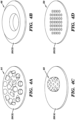
- FIGS. 4A-4D other types of covers 20(2)-20(5) which could be seated over and utilized to assist with multi-directional sensitivity of the pressure sensor 18 are illustrated in FIGS. 4A-4D .
- the cover 20(2) has a plurality of funnel shaped passages 44 angled towards the center;
- the cover 20(3) has a centralized funnel shaped structure 46 designed to direct the compression wave to the interior of the dosimetry apparatus 10;
- the cover 20(4) has a plastic dome 48 with perforations;
- the cover 20(5) has a matrix of perforations 50 which all are designed to operate as cover 20(1) with or without any added structures as discussed above, although other types and numbers of covers with other shapes and configurations and which may incorporate a porous matrix to improve uniformity and/or fine mesh screen for dust exclusion could be used.
- the inertial monitoring unit 22 is a low-g (for example 16g) three -axis accelerometer to capture linear acceleration in three axes, although other types (such as a high-g accelerometer, for example >100g) and numbers of inertial measurement units could be used.
- the inertial measurement unit 22 could be a gyroscope which records rotational acceleration.
- the three-axis acceleration information from the inertial monitoring unit 22 can be used by the dosimetry processing device 12 to determine the vector of movement coincident with the arrival of the pressure shock front. This indicates the relative angle of the dosimetry apparatus 10 to the force allowing for compensation of the measured pressure profile including the levels of the stored reading thresholds to improve accuracy and precision with respect to the obtained readings and the identification of events.
- the shock mounting system 24 is used to suspend a printed circuit board 56 which has the dosimetry processing device 12 with the memory 14, the interface device 16, the pressure sensor 18, the inertial monitoring unit 22, the atmospheric sensor 28, and the power system 30 in the housing 11, although other types and numbers of elements and other components could be on the printed circuit board and suspended.
- the result is an expansion of the dynamic range of the dosimetry apparatus 10 at the expense of resolution.
- the physical gap between the printed circuit board 56 and the housing 11 is determined by the mass and maximum acceleration impulse.
- the shock mounting system 24 includes elastic suspension devices 52 and viscoelastic polymer bushings 54, although the apparatus 24 can include other types and numbers of shock mounting systems, such as a grease damping system.
- the printed circuit board 56 is suspend by three points using the elastic suspension devices 52, although the printed circuit board 56 could be suspended by other numbers of points in other manners and other systems, device, and components could be suspended, such as just the inertial monitoring unit 22.
- the use of the two attenuation schemes with the shock mounting system 24, such as the elastic suspension devices 52 and the viscoelastic polymer bushings 54 in this example provides a multiplicative effect reducing the requirements on each of these shock mounting systems. This also reduces the required space between the printed circuit board 56 and the housing 11 which reduces the overall size of the dosimetry apparatus 10.
- the mounting system 26 is used to mount the housing 11 of the dosimetry apparatus 10 to an entity, such as an object or person.
- the mounting system 26 comprises a strap that can be mounted to a helmet strap or fabric webs on uniforms, although other types of mounting systems 26 could be used.
- the helmet strap for the mounting system 26 must be non-stiff/flexible/elastomeric, so as to damp any incident vibration/shock, but short enough and well fixed enough to couple the dosimeter effectively into the mass you are trying to measure.
- Detachably/compliantly mounting of the dosimeter apparatus 10 with a mounting system 26, such as the illustrated helmet strap allows mounting more directly to a lower stiffness location which in turn couples the dosimetry apparatus 10 into a higher mass than traditional helmet mounting. This coupling provides more significant acceleration measurements for risk injury assessment than connection to a detached part of a wearer, such as a helmet. Both the lower stiffness of the mounting strap and the higher mass the dosimetry apparatus 10 is attached to are part of the lower resultant acceleration.
- mounting systems 26 may include adhesive, hook and loop mating fasteners, fabric wraps with hook and loop mating fasteners, elastic straps with or without snaps, hooks, grommet snaps embedded in the housing and attached to a helmet strap, and non-elastic straps with a tightening mechanism.
- the elastic strap can comprise an elastic loop that hooks onto a portion of the housing 11, wraps around the desired entity, and attaches to another portion of the housing to secured the housing 11.
- the atmospheric sensor 28 is coupled to the dosimetry processing device 12 and provides atmospheric readings within the dosimetry apparatus 10, although other types and numbers of atmospheric monitors could be used and the atmospheric sensor 28 could be positioned to take other readings
- the power system 30 includes a battery 36 coupled to a regulator 38 which is coupled to the dosimetry processing device 12, although other types of power systems with other types and numbers of components, such as one with an energy harvester and/or without a regulator 38 could be used.
- the regulator 38 is coupled to regulate power provided by the battery 36 to the dosimetry processing device 12. Additionally, in this example power for the pressure sensor 18, the inertial measurement unit 22, the atmospheric sensor 28, and/or the strain gauge 29 is coupled directly from the dosimetry processing device 12 to save power, although other types and numbers of devices and systems could be coupled directly to the dosimetry processing device 12 to provide power.
- Additional, power management may be achieved through stored programmed instructions executed by the dosimetry processing device 12 for a standard monitoring mode, a lower power monitoring mode and a sleep mode, although other types and numbers of modes can be used.
- the inertial measurement unit 22 provides data to the dosimetry processing device 12 to identify periods of inactivity to trigger the lower power standby mode when minimal activity is identified or sleep mode when prolong periods of inactivity are identified for power savings. Activity sensing by the inertial measurement unit 22 enables the dosimetry processing device 12 to switch to standard monitoring mode with a high sampling rate for the inertial measurement unit 22 and pressure sensor 18 by way of example.
- peripheral devices such as pressure sensor 18, inertial measurement unit 22, and atmospheric sensor 28 by way of example only, are powered through digital input/output (I/O) pins 72 on the processor in the dosimetry processing device 12 rather than from a power bus.
- I/O digital input/output
- the regulator 38 is enabled through an I/O input/output (I/O) pin on the processor in the dosimetry processing device 12. This allows the dosimetry processing device 12 to be completely turned off to extend shelf life.
- the dosimetry processing device 12 is activated either through the button or powering through USB
- the engagement device 32 such as a button by way of example only, is coupled to the dosimetry processing device 12, although the engagement device could be coupled in other manners.
- the engagement device 32 can be used to request an output of readings including of identified events, stored events and/or assessments of the readings.
- other types and numbers of mechanisms for engaging the dosimetry processing device 12 can be used, such as another computing device coupling to the dosimetry processing device 12 through the interface 16 to request and obtain output data and other information, download a time and date stamp, set and/or reprogram criteria and other parameters by way of example only.
- the series of different colored LEDs with different numeric indicators 34(1)-34(3) are used to provide a status indication for the output stored readings and of the assessment of the stored readings associated with identified events to provide immediate triage of the severity of an event, although other types and numbers of displays which provide other types of outputs can be used.
- LED 34(1) is green colored and has a numeric indicator of zero
- LED 34(2) is yellow colored and has a numeric indicator of one
- LED 34(1) is red colored and has a numeric indicator of two, although other colors and symbols could be used.
- dosimetry pressure sensing apparatuses 55(1) and 55(2) are illustrated.
- the dosimetry pressure sensing apparatuses 55(1) and 55(2) are the same as the dosimetry apparatus 10, except as described and illustrated herein.
- the dosimetry pressure sensing apparatus 55(1) has a pressure sensor 18 in a housing 60 with a cover 20(1) seated over the pressure sensor 18, although the dosimetry pressure sensing apparatuses could have other numbers and types of system, devices and elements in other configurations.
- the dosimetry pressure sensing apparatuses 55(1) has conductors 62 coupled to the pressure sensor 18 extending out from the housing 60 to couple to an external processing device as opposed to the internal processing device 12 in dosimetry apparatus 10.
- the dosimetry pressure sensing apparatus 55(2) has two pressure sensors 18 on opposing sides of the housing 60 with a cover 20(1) seated over each of the pressure sensors 18, although the dosimetry pressure sensing apparatuses could have other numbers and types of system, devices and elements in other configurations, such as other locations for and numbers of pressure sensors. Additionally, the dosimetry pressure sensing apparatuses 55(2) has conductors 62 coupled to each of the pressure sensors 18 extending out from the housing 60 to couple to an external processing device as opposed to the internal processing device 12 in dosimetry apparatus 10.
- At step 100 at least one dosimetry apparatus 10 is secured using the mounting system 26 to a location on an object, although other types and manners for securing the one or more dosimetry apparatuses 10 to the object can be used.
- the dosimetry processing device in the dosimetry apparatus 10 obtains readings from a single pressure sensor 18 and the inertial measurement unit 22, although the dosimetry apparatus 10 can obtain readings from other types and numbers of sensors.
- the pressure sensor 18 is a single pressure sensor which obtains pressure readings, although other types and numbers of pressure sensors could be used.
- the inertial measurement unit 22 is a three-axis accelerometer which obtains linear acceleration readings in real time, although other types of inertial measurement units can be used, such as a gyroscope which obtains rotational acceleration readings.
- step 104 the dosimetry processing device 12 stores the obtained pressure readings from the pressure sensor 18, acceleration readings from the inertial measurement unit 22, and atmospheric readings from the atmospheric sensor 28, although other types and amounts of readings and other data could be stored in other locations and manners.
- the dosimetry processing device 12 also may conduct an analysis based on the obtained pressure readings, acceleration readings and/or atmospheric readings, although other types and numbers of analyses based on other readings and data can be performed. Additionally, the dosimetry processing device 12 assesses the severity of the event based on the obtained pressure readings, acceleration readings, and/or atmospheric readings, although other manners for conducting an analysis can be used. The dosimetry processing device 12 stores the conducted analysis and assessed severity in memory 14, although the conducted analyses assessed severity can be stored in other locations and manners.
- the dosimetry processing device 12 determines whether an output is requested, such as by activation of the engagement device 32 or a request via the interface 16, such as a USB, from another computing device, although other manners for output requests could be used.
- the activating of the engagement device could trigger a display on one of the LEDs 34(1)-34(3), although other types of outputs could be triggered, such as an output of data and other information.
- the engagement device 32 also can have other functions, such as providing outputting different information based on a number of times the button is pressed or the length of time the button is pressed or powering on or off the dosimetry apparatus 10.
- the request for data through the interface 16 from another computing device can be for all or requested portions of the stored data.
- step 108 the dosimetry processing device 12 determines an output has not been requested, then the No branch is taken back to step 102 as described earlier. If in step 108, the dosimetry processing device 12 determines an output has been requested, then the Yes branch is taken back to step 110.
- the dosimetry processing device 12 provides the requested output, such as a display on one of the LEDs 34(1)-34(3) or an output of one or more of the stored readings, the identified event, a determined injury risk assessment based on the conducted analysis, data relating to switches between power modes, data relating to output requests, and/or identified false positive events and related data by way of example only via the interface 16, although the information could be output to other devices, other types and amounts of information and other data could be provided and the information and data can be obtained in other manners, such as through a connection with another computing device interacting with the dosimetry processing device 12 via the interface 16 .
- the requested output such as a display on one of the LEDs 34(1)-34(3) or an output of one or more of the stored readings, the identified event, a determined injury risk assessment based on the conducted analysis, data relating to switches between power modes, data relating to output requests, and/or identified false positive events and related data by way of example only via the interface 16, although the information could be output to other devices, other types
- the dosimetry processing device 12 can output the identified event with determined injury risk assessment based on the conducted analysis by illumination of one of the LEDs 34(1) with a numeric indicator in response to the activation by the engagement device 32, although other types and amounts of information could be provided. For example, if the determined injury risk assessment for the identified event is moderate, e.g. within a first range of one or more of the first thresholds then the yellow colored LED 34(2) with the numeric indicator of one is illuminated/flashed. If the determined injury risk assessment for the identified event is severe, e.g. above a first range of one or more of the first thresholds then the red colored LED 34(3) with the numeric indicator of two is illuminated/flashed.
- the green colored LED 34(1) with the numeric indicator of zero is illuminated. Additionally, a requested output could trigger the dosimetry processing device 12 to output the stored readings, determined direction and other data described in the examples herein with or without the assessment information via the interface device 16 to another computing device. Next, this method can return back to step 102 until the exemplary dosimetry apparatus 10 is turned off or the power runs out.
- this technology provides a more effective and efficient event monitoring dosimetry apparatus.
- event data from a blast or blow can be captured and utilized to provide real time analysis of exposed individuals. Additionally, this technology can capture and provide event data that will help to provide a better understanding the mechanisms of traumatic brain injury resulting from an explosive blast, blow, or other event.
Landscapes
- Health & Medical Sciences (AREA)
- Life Sciences & Earth Sciences (AREA)
- Engineering & Computer Science (AREA)
- Biomedical Technology (AREA)
- Public Health (AREA)
- Medical Informatics (AREA)
- Physics & Mathematics (AREA)
- General Health & Medical Sciences (AREA)
- Pathology (AREA)
- Biophysics (AREA)
- Veterinary Medicine (AREA)
- Heart & Thoracic Surgery (AREA)
- Physiology (AREA)
- Molecular Biology (AREA)
- Surgery (AREA)
- Animal Behavior & Ethology (AREA)
- Neurology (AREA)
- General Physics & Mathematics (AREA)
- Computer Vision & Pattern Recognition (AREA)
- Signal Processing (AREA)
- Psychiatry (AREA)
- Artificial Intelligence (AREA)
- Epidemiology (AREA)
- Primary Health Care (AREA)
- Dentistry (AREA)
- Oral & Maxillofacial Surgery (AREA)
- Psychology (AREA)
- Neurosurgery (AREA)
- Business, Economics & Management (AREA)
- General Business, Economics & Management (AREA)
- Data Mining & Analysis (AREA)
- Databases & Information Systems (AREA)
- Measuring Fluid Pressure (AREA)
- Force Measurement Appropriate To Specific Purposes (AREA)
- Measurement Of The Respiration, Hearing Ability, Form, And Blood Characteristics Of Living Organisms (AREA)
- Measuring And Recording Apparatus For Diagnosis (AREA)
- Professional, Industrial, Or Sporting Protective Garments (AREA)
Description
- This application claims the benefit of
U.S. Provisional Patent Application Serial No. 61/446,369 filed February 24, 2011 - This technology generally relates to monitoring devices and methods and, more particularly, to event monitoring dosimetry apparatuses and methods thereof
- Traumatic brain injury (TBI) from an explosive blast remains a significant problem for military personnel, especially those involved in counter insurgency operations. Mild to moderate TBI may be difficult to detect immediately post event, with cognitive or motor deficits manifesting weeks or months post event.
- Additionally, exposure to other types of blows and other types of events is a significant problem for other individuals as well. For example, recreational and professional athletes in many sport activities are routinely exposed to blows and other types of events with unknown individual or cumulative effects. Additionally, bike and motorcycle riders may experience some type of blow or other event by way of example only.
- Currently, there is no widely deployed system to dose the exposure to an explosive blast, blow or other type of event. Given the nature of TBI, the wide variability in explosions, blows and other events and as well as the physical configurations during a blast events, and the variability in human response to each blast event, a widely deployed system to all personnel in a theater is needed to build a database of sufficient size to allow real-time dosimeter data to be used for triage and to monitor and assess military and non-military personnel depending on the particular application.
-
US 2010/171514 describes a dosimeter employed to passively record a peak pressure (e.g., a peak blast pressure) and/or a maximum acceleration experienced by the dosimeter
US 2010/307223 provides an apparatus for recording information about an event resulting in application of a force to a body. The apparatus comprises data recording means for recording the information, sensor means for sensing a parameter which enables a predetermined source of force to be distinguished from another, different source of force, and control means responsive to the sensed parameter for controlling the data recording means. The sensor means may comprise a pressure sensor for sensing shockwaves resulting from an explosive force and the resulting signal used to distinguish from other events, such as blunt impacts. The pressure signal may be used to control the storage of acceleration data for injury analysis. -
US 7,378,954 describes a safety indicator that monitors environment conditions detrimental to humans e.g., hazardous gases, air pollutants, low oxygen, radiation levels of EMF or RF and microwave, temperature, humidity and air pressure retaining a three month history to upload to a PC via infra red data interface or phone link. Contaminants are analyzed and compared to stored profiles to determine its classification and notify user of an adversity by stored voice messages from, via alarm tones and associated flashing LED, via vibrator for silent operation or via LCD. Environmental radiation sources are monitored and auto-scaled. Instantaneous radiation exposure level and exposure duration data are stored for later readout as a detector and dosimeter. Scans for EMF allow detection with auto scaling of radiation levels and exposure durations are stored for subsequent readout.; Electronic bugs can be found with a high sensitivity EMF range setting. Ambient temperature measurements or humidity and barometric pressure can be made over time to predict weather changes. A PCS RF link provides wireless remote communications in a first responder military use by upload of alarm conditions, field measurements and with download of command instructions. The link supports reception of telemetry data for real time remote monitoring of personnel via the wrist band for blood pressure, temperature, pulse rate and blood oxygen levels are transmitted. Commercial uses include remote environmental data collection and employee assignment tasking. GPS locates personnel and reporting coordinates associated with alarm occurrences and associated environmental measurements. -
US 2010/326192 describes methods and devices for a miniature, ultra-low power impact recorder for detecting, quantifying and recording the energy of an explosive blast or ballistic projectile impact. In one embodiment, the impact recorder can include a sensor comprised of an array of electromechanical resonators that is sensitive to the vibrations produced in selected, discrete frequency ranges that approximate the spectral signature characteristics of the shockwave resulting from the ballistic impact event, even after traveling through impacted material or body tissues. -
US 2010/098270 describes a communication apparatus includes a bone conduction communication apparatus with a housing having a shape which is conformable to at least a portion of at least one tooth of a user; a transceiver mounted in the housing; and a transducer disposed within or upon the housing and in vibratory communication with a surface of the at least one tooth to transmit sound through the at least one tooth. A positioning system is provided to transmit positional information to the transceiver to be delivered to the transducer; and a communication device links the transceiver with a second person. The electronic and transducer assembly may receive incoming sounds either directly or through a receiver to process and amplify the signals and transmit the processed sounds via a vibrating transducer element coupled to a tooth or other bone structure, such as the maxillary, mandibular, or palatine bone structure. - According to the present invention there is provided a multiple use dosimetry apparatus as defined in the appended
claim 1. Further optional features of the invention are recited in the associated dependent claims. - This technology provides a number of advantages including providing a more effective and efficient event monitoring dosimetry apparatus. With this technology, event data from a blast or blow can be captured and utilized to guide evaluation of exposed individuals. Additionally, this technology can capture and provide event data that will help to provide a better understanding the mechanisms of traumatic brain injury resulting from an explosive blast, blow, or other event. Further, the exemplary cover provides improved omni-directionality, while the exemplary shock mounting enables capture of peak accelerations with lower g- accelerometers. Even further, this technology provides effective omni-directionality pressure sensors without internal processing capabilities.
- This technology can be used in a variety of different applications, such as for the military, sporting activities, and other daily activities by way of example only. For military applications, this technology could be helmet mounted, helmet strap mounted, worn on the torso, and/or mounted within vehicle cabins. For sporting activities, this technology could be mounted within helmets or on uniforms. For daily activities, this could be mounted to helmets used for bicycles and motorcycles by way of example.
-
-
FIG. 1 is a diagram of an exemplary event monitoring dosimetry apparatus; -
FIGS. 2A-2C are perspective view of the exemplary event monitoring dosimetry apparatus; -
FIG. 3 is a perspective view of the shock mounting devices in the exemplary event monitoring dosimetry apparatus -
FIGS. 4A-4D are perspective views of different exemplary covers for an event monitoring dosimetry apparatus; -
FIGS. 5A-5B are perspective views of exemplary dosimetry pressure sensors; and -
FIG. 6 is an exemplary method for monitoring events with the exemplary event monitoring dosimetry apparatus. - An exemplary event
monitoring dosimetry apparatus 10 is illustrated inFIGS. 1-3 . The eventmonitoring dosimetry apparatus 10 includes ahousing assembly 11 with adosimetry processing device 12 with amemory 14, aninterface device 16, apressure sensor 18, a cover 20(1), aninertial monitoring unit 22,shock mounting system 24,mounting system 26, anatmospheric sensor 28, apower system 30, anengagement device 32, and a series of different colored LEDs with different numeric indicators 34(1)-34(3), although theapparatus 10 could include other types and numbers of systems, devices, components and elements in other configurations. This technology provides a number of advantages including provide a more effective and efficient event monitoring dosimetry apparatus. - Referring more specifically to
FIG. 1 , thedosimetry processing device 12 comprises one or more processors internally coupled to thememory 14 by a bus or other links, although other numbers and types of systems, devices, components, and elements in other configurations and locations can be used. The one or more processors in thedosimetry processing device 12 executes a program of stored instructions for one or more aspects of the present technology as described and illustrated by way of the examples herein, although other types and numbers of processing devices and logic could be used and the processor could execute other numbers and types of programmed instructions. Thememory 14 in thedosimetry processing device 12 stores these programmed instructions for one or more aspects of the present technology as described and illustrated herein, although some or all of the programmed instructions could be stored and executed elsewhere. A variety of different types of memory storage devices, such as a solid state memory, can be used for thememory 14 in thedosimetry processing device 12. The flow chart shown inFIG. 6 is representative of example steps or actions of this technology that may be embodied or expressed as one or more non-transitory computer or machine readable instructions stored inmemory 14 that may be executed by the one or more processors. - The
interface device 16 in thedosimetry processing device 12 is used to operatively couple and communicate between thedosimetry processing device 12 and one or more external computing or storage devices, although other types and numbers of communication networks or systems with other types and numbers of connections and configurations can be used. - Although an example of the
dosimetry processing device 12 is described herein, it can be implemented on any suitable computer system or computing device. It is to be understood that the devices and systems of the examples described herein are for exemplary purposes, as many variations of the specific hardware and software used to implement the examples are possible, as will be appreciated by those skilled in the relevant art(s). - Furthermore, the system of the examples may be conveniently implemented using one or more general purpose computer systems, microprocessors, digital signal processors, and micro-controllers, programmed according to the teachings of the examples, as described and illustrated herein, and as will be appreciated by those ordinary skill in the art.
- One or more aspects of examples may also be embodied as a non-transitory computer readable medium having instructions stored thereon for one or more aspects of the present technology as described and illustrated by way of the examples herein, as described herein, which when executed by a processor, cause the processor to carry out the steps necessary to implement the methods of the examples, as described and illustrated herein.
- The
pressure sensor 18 is coupled to thedosimetry processing device 12, although thepressures sensor 18 could be coupled to other types and numbers of devices. In this example, thepressure sensor 18 is a single pressure sensor to help achieve low cost and disposability parameters, although other types and numbers of pressure sensors could be used. Additionally, in this example thepressure sensor 18 is insensitive to direction and will substantially detect the same pressure waveform independent of the relative orientation of thepressure sensor 18 to the pressure front, although the pressure sensor could have other degrees of improved directional sensitivity, such as fifty percent or more by way of example only. To have multi-directional sensitivity, in this example thepressure sensor 18 is positioned below a wire mesh dome cover 20(1) which extends out and away from thehousing 11, although other types of covers could be used to enable multi-directional sensing by thepressure sensor 18. - The mesh dome cover 20(1) comprises a very fine mesh layer, which acts as a filter for particles, sandwiched between two larger mesh layers used for structural strength, although the mesh dome cover 20(1) can be made with other types and numbers of layers. Additionally, the mesh dome cover 20(1) can be made of a variety of different types of materials, such as metallic materials, non-metallic materials, and fabric weaves as well as combinations of different materials by way of example only. Further, a floating body, such as a sphere or beads which are loose, other structures such as beads which are packed in and can not move or a porous matrix structure also may also be inserted within the mesh dome cover 20(1) to improve omni-directionality. Further, a
check valve 70 can be situated within the mesh dome cover 20(1) to improve omni-directionality as shown inFIG. 2C . - By way of example only, other types of covers 20(2)-20(5) which could be seated over and utilized to assist with multi-directional sensitivity of the
pressure sensor 18 are illustrated inFIGS. 4A-4D . For example: the cover 20(2) has a plurality of funnel shapedpassages 44 angled towards the center; the cover 20(3) has a centralized funnel shapedstructure 46 designed to direct the compression wave to the interior of thedosimetry apparatus 10; the cover 20(4) has aplastic dome 48 with perforations; and the cover 20(5) has a matrix ofperforations 50 which all are designed to operate as cover 20(1) with or without any added structures as discussed above, although other types and numbers of covers with other shapes and configurations and which may incorporate a porous matrix to improve uniformity and/or fine mesh screen for dust exclusion could be used. - Referring back to
FIG. 1 , theinertial monitoring unit 22 is a low-g (for example 16g) three -axis accelerometer to capture linear acceleration in three axes, although other types (such as a high-g accelerometer, for example >100g) and numbers of inertial measurement units could be used. For example, theinertial measurement unit 22 could be a gyroscope which records rotational acceleration. To account for differences in pressure readings from thepressure sensor 18 which depend on the incident direction of the force, the three-axis acceleration information from theinertial monitoring unit 22 can be used by thedosimetry processing device 12 to determine the vector of movement coincident with the arrival of the pressure shock front. This indicates the relative angle of thedosimetry apparatus 10 to the force allowing for compensation of the measured pressure profile including the levels of the stored reading thresholds to improve accuracy and precision with respect to the obtained readings and the identification of events. - Referring to
FIGS. 3 , theshock mounting system 24 is used to suspend a printedcircuit board 56 which has thedosimetry processing device 12 with thememory 14, theinterface device 16, thepressure sensor 18, theinertial monitoring unit 22, theatmospheric sensor 28, and thepower system 30 in thehousing 11, although other types and numbers of elements and other components could be on the printed circuit board and suspended. The result is an expansion of the dynamic range of thedosimetry apparatus 10 at the expense of resolution. The physical gap between the printedcircuit board 56 and thehousing 11 is determined by the mass and maximum acceleration impulse. - In this example, the
shock mounting system 24 includeselastic suspension devices 52 andviscoelastic polymer bushings 54, although theapparatus 24 can include other types and numbers of shock mounting systems, such as a grease damping system. Additionally, in this example the printedcircuit board 56 is suspend by three points using theelastic suspension devices 52, although the printedcircuit board 56 could be suspended by other numbers of points in other manners and other systems, device, and components could be suspended, such as just theinertial monitoring unit 22. The use of the two attenuation schemes with theshock mounting system 24, such as theelastic suspension devices 52 and theviscoelastic polymer bushings 54 in this example, provides a multiplicative effect reducing the requirements on each of these shock mounting systems. This also reduces the required space between the printedcircuit board 56 and thehousing 11 which reduces the overall size of thedosimetry apparatus 10. - Referring to
FIG. 2C , the mountingsystem 26 is used to mount thehousing 11 of thedosimetry apparatus 10 to an entity, such as an object or person. In this example, the mountingsystem 26 comprises a strap that can be mounted to a helmet strap or fabric webs on uniforms, although other types of mountingsystems 26 could be used. The helmet strap for the mountingsystem 26 must be non-stiff/flexible/elastomeric, so as to damp any incident vibration/shock, but short enough and well fixed enough to couple the dosimeter effectively into the mass you are trying to measure. Detachably/compliantly mounting of thedosimeter apparatus 10 with a mountingsystem 26, such as the illustrated helmet strap by way of example allows mounting more directly to a lower stiffness location which in turn couples thedosimetry apparatus 10 into a higher mass than traditional helmet mounting. This coupling provides more significant acceleration measurements for risk injury assessment than connection to a detached part of a wearer, such as a helmet. Both the lower stiffness of the mounting strap and the higher mass thedosimetry apparatus 10 is attached to are part of the lower resultant acceleration. - By way of example only, other types of mounting
systems 26 may include adhesive, hook and loop mating fasteners, fabric wraps with hook and loop mating fasteners, elastic straps with or without snaps, hooks, grommet snaps embedded in the housing and attached to a helmet strap, and non-elastic straps with a tightening mechanism. The manners by which these attachment mechanisms operate are well known to those ordinary skill in the art and thus will not be described in detail here. For example, the elastic strap can comprise an elastic loop that hooks onto a portion of thehousing 11, wraps around the desired entity, and attaches to another portion of the housing to secured thehousing 11. - The
atmospheric sensor 28 is coupled to thedosimetry processing device 12 and provides atmospheric readings within thedosimetry apparatus 10, although other types and numbers of atmospheric monitors could be used and theatmospheric sensor 28 could be positioned to take other readings - The
power system 30 includes abattery 36 coupled to aregulator 38 which is coupled to thedosimetry processing device 12, although other types of power systems with other types and numbers of components, such as one with an energy harvester and/or without aregulator 38 could be used. Theregulator 38 is coupled to regulate power provided by thebattery 36 to thedosimetry processing device 12. Additionally, in this example power for thepressure sensor 18, theinertial measurement unit 22, theatmospheric sensor 28, and/or the strain gauge 29 is coupled directly from thedosimetry processing device 12 to save power, although other types and numbers of devices and systems could be coupled directly to thedosimetry processing device 12 to provide power. Additional, power management may be achieved through stored programmed instructions executed by thedosimetry processing device 12 for a standard monitoring mode, a lower power monitoring mode and a sleep mode, although other types and numbers of modes can be used. Theinertial measurement unit 22 provides data to thedosimetry processing device 12 to identify periods of inactivity to trigger the lower power standby mode when minimal activity is identified or sleep mode when prolong periods of inactivity are identified for power savings. Activity sensing by theinertial measurement unit 22 enables thedosimetry processing device 12 to switch to standard monitoring mode with a high sampling rate for theinertial measurement unit 22 andpressure sensor 18 by way of example. In this example, all peripheral devices, such aspressure sensor 18,inertial measurement unit 22, andatmospheric sensor 28 by way of example only, are powered through digital input/output (I/O) pins 72 on the processor in thedosimetry processing device 12 rather than from a power bus. This allows peripheral devices to be turned off via the processor in thedosimetry processing device 12 saving power. Theregulator 38 is enabled through an I/O input/output (I/O) pin on the processor in thedosimetry processing device 12. This allows thedosimetry processing device 12 to be completely turned off to extend shelf life. Thedosimetry processing device 12 is activated either through the button or powering through USB - The
engagement device 32, such as a button by way of example only, is coupled to thedosimetry processing device 12, although the engagement device could be coupled in other manners. Theengagement device 32 can be used to request an output of readings including of identified events, stored events and/or assessments of the readings. Additionally, other types and numbers of mechanisms for engaging thedosimetry processing device 12 can be used, such as another computing device coupling to thedosimetry processing device 12 through theinterface 16 to request and obtain output data and other information, download a time and date stamp, set and/or reprogram criteria and other parameters by way of example only. - The series of different colored LEDs with different numeric indicators 34(1)-34(3) are used to provide a status indication for the output stored readings and of the assessment of the stored readings associated with identified events to provide immediate triage of the severity of an event, although other types and numbers of displays which provide other types of outputs can be used. In this example, LED 34(1) is green colored and has a numeric indicator of zero, LED 34(2) is yellow colored and has a numeric indicator of one, and LED 34(1) is red colored and has a numeric indicator of two, although other colors and symbols could be used.
- Referring to
FIGS. 5A-5B examples of dosimetry pressure sensing apparatuses 55(1) and 55(2) are illustrated. The dosimetry pressure sensing apparatuses 55(1) and 55(2) are the same as thedosimetry apparatus 10, except as described and illustrated herein. In this example, the dosimetry pressure sensing apparatus 55(1) has apressure sensor 18 in ahousing 60 with a cover 20(1) seated over thepressure sensor 18, although the dosimetry pressure sensing apparatuses could have other numbers and types of system, devices and elements in other configurations. Additionally, the dosimetry pressure sensing apparatuses 55(1) hasconductors 62 coupled to thepressure sensor 18 extending out from thehousing 60 to couple to an external processing device as opposed to theinternal processing device 12 indosimetry apparatus 10. Additionally, in this example, the dosimetry pressure sensing apparatus 55(2) has twopressure sensors 18 on opposing sides of thehousing 60 with a cover 20(1) seated over each of thepressure sensors 18, although the dosimetry pressure sensing apparatuses could have other numbers and types of system, devices and elements in other configurations, such as other locations for and numbers of pressure sensors. Additionally, the dosimetry pressure sensing apparatuses 55(2) hasconductors 62 coupled to each of thepressure sensors 18 extending out from thehousing 60 to couple to an external processing device as opposed to theinternal processing device 12 indosimetry apparatus 10. - Referring to
FIG. 6 , an exemplary method for monitoring events with the exemplary event monitoring dosimetry apparatus will now be described. Atstep 100, at least onedosimetry apparatus 10 is secured using the mountingsystem 26 to a location on an object, although other types and manners for securing the one ormore dosimetry apparatuses 10 to the object can be used. - In
step 102, the dosimetry processing device in thedosimetry apparatus 10 obtains readings from asingle pressure sensor 18 and theinertial measurement unit 22, although thedosimetry apparatus 10 can obtain readings from other types and numbers of sensors. In this example, thepressure sensor 18 is a single pressure sensor which obtains pressure readings, although other types and numbers of pressure sensors could be used. Additionally, in this example, theinertial measurement unit 22 is a three-axis accelerometer which obtains linear acceleration readings in real time, although other types of inertial measurement units can be used, such as a gyroscope which obtains rotational acceleration readings. - In
step 104, thedosimetry processing device 12 stores the obtained pressure readings from thepressure sensor 18, acceleration readings from theinertial measurement unit 22, and atmospheric readings from theatmospheric sensor 28, although other types and amounts of readings and other data could be stored in other locations and manners. - In
step 106, thedosimetry processing device 12 also may conduct an analysis based on the obtained pressure readings, acceleration readings and/or atmospheric readings, although other types and numbers of analyses based on other readings and data can be performed. Additionally, thedosimetry processing device 12 assesses the severity of the event based on the obtained pressure readings, acceleration readings, and/or atmospheric readings, although other manners for conducting an analysis can be used. Thedosimetry processing device 12 stores the conducted analysis and assessed severity inmemory 14, although the conducted analyses assessed severity can be stored in other locations and manners. - In
step 108, thedosimetry processing device 12 determines whether an output is requested, such as by activation of theengagement device 32 or a request via theinterface 16, such as a USB, from another computing device, although other manners for output requests could be used. The activating of the engagement device could trigger a display on one of the LEDs 34(1)-34(3), although other types of outputs could be triggered, such as an output of data and other information. Theengagement device 32 also can have other functions, such as providing outputting different information based on a number of times the button is pressed or the length of time the button is pressed or powering on or off thedosimetry apparatus 10. The request for data through theinterface 16 from another computing device can be for all or requested portions of the stored data. If instep 108, thedosimetry processing device 12 determines an output has not been requested, then the No branch is taken back to step 102 as described earlier. If instep 108, thedosimetry processing device 12 determines an output has been requested, then the Yes branch is taken back tostep 110. Instep 110, thedosimetry processing device 12 provides the requested output, such as a display on one of the LEDs 34(1)-34(3) or an output of one or more of the stored readings, the identified event, a determined injury risk assessment based on the conducted analysis, data relating to switches between power modes, data relating to output requests, and/or identified false positive events and related data by way of example only via theinterface 16, although the information could be output to other devices, other types and amounts of information and other data could be provided and the information and data can be obtained in other manners, such as through a connection with another computing device interacting with thedosimetry processing device 12 via theinterface 16 . In this example, thedosimetry processing device 12 can output the identified event with determined injury risk assessment based on the conducted analysis by illumination of one of the LEDs 34(1) with a numeric indicator in response to the activation by theengagement device 32, although other types and amounts of information could be provided. For example, if the determined injury risk assessment for the identified event is moderate, e.g. within a first range of one or more of the first thresholds then the yellow colored LED 34(2) with the numeric indicator of one is illuminated/flashed. If the determined injury risk assessment for the identified event is severe, e.g. above a first range of one or more of the first thresholds then the red colored LED 34(3) with the numeric indicator of two is illuminated/flashed. If there is no event recorded, the green colored LED 34(1) with the numeric indicator of zero is illuminated. Additionally, a requested output could trigger thedosimetry processing device 12 to output the stored readings, determined direction and other data described in the examples herein with or without the assessment information via theinterface device 16 to another computing device. Next, this method can return back to step 102 until theexemplary dosimetry apparatus 10 is turned off or the power runs out. - Accordingly, as illustrated and described with reference to the examples herein this technology provides a more effective and efficient event monitoring dosimetry apparatus. With this technology, event data from a blast or blow can be captured and utilized to provide real time analysis of exposed individuals. Additionally, this technology can capture and provide event data that will help to provide a better understanding the mechanisms of traumatic brain injury resulting from an explosive blast, blow, or other event.
- Having thus described the basic concept of the invention, it will be rather apparent to those skilled in the art that the foregoing detailed disclosure is intended to be presented by way of example only, and is not limiting. Various alterations, improvements, and modifications will occur and are intended to those skilled in the art, though not expressly stated herein. Additionally, the recited order of processing elements or sequences, or the use of numbers, letters, or other designations therefore, is not intended to limit the claimed processes to any order except as may be specified in the claims. The invention is defined by the appended claims.
Claims (13)
- A dosimetry apparatus (10) comprising:a pressure sensor (18) capable of detecting a pressure waveform disposed in a housing (11);a cover (20(1)) configured to permit compression waves to pass through, the cover (20(1)) is seated over the sensor (18) and comprises a mesh structure comprising a particle filtering mesh layer configured to exclude dust seated against a structural mesh layer configured to provide structural integrity to the particle filtering mesh layer; anda dosimetry processing device (12) with a memory (14) coupled to the sensor (18) in the housing (11), the dosimetry processing device (12) configured to execute programmed instructions stored in the memory (14) comprising obtaining readings from the sensor (18), storing the readings when obtained, conducting an analysis based on the obtained readings and outputting at least one of the stored readings or the conducted analysis,whereinthe cover (20(1)) comprises arranged openings, perforations or passages that allow a multidirectional sensitivity such that the pressure sensor (18) has multi-directional sensitivity.
- The apparatus (10) as set forth in claim 1 further comprising at least one conductor (62) coupled to the sensor (18) and extending out from the housing (11).
- The apparatus (10) as set forth in claim 1 or 2 wherein the mesh structure further comprises a check valve (70) that controls flow into the housing (11).
- The apparatus (10) as set forth in any preceding claim further comprising a floating body seated within the mesh structure.
- The apparatus (10) as set forth in any preceding claim further comprising beaded structures packed within the mesh structure.
- The apparatus (10) as set forth in any preceding claim further comprising a porous matrix structure within the mesh structure.
- The apparatus (10) as set forth in any preceding claim wherein the apparatus comprises an inertial measurement unit (22).
- The apparatus (10) as set forth in any preceding claim further comprising a display device coupled to the dosimetry processing device (12), the display device configured to illustrate the stored readings.
- The apparatus (10) as set forth in claim 8 wherein the display device comprises a plurality of different colored status indicator devices (34(1),34(2),34(3)) each with a different symbol to illustrate a severity level of the stored reading.
- The apparatus (10) as set forth in claim 9 further comprising an engagement device (32) coupled to the dosimetry processing device (12), wherein the dosimetry processing device (12) is configured to execute programmed instructions stored in the memory further comprising providing a status indicator of the stored readings on the display device in response to an activation of the engagement device (32).
- The apparatus (10) as set forth in any preceding claim configured for coupling power for at least one peripheral device directly from the dosimetry processing device (12).
- The apparatus (10) as set forth in claim 7 further comprising:a shock mounting apparatus (24) configured for shock mounting the inertial measurement unit (22) in the housing (11); andwherein the dosimetry processing device (12) with a memory (14) is coupled to the inertial measurement unit (22) in the housing (11).
- The apparatus (10) as set forth in any preceding claim further comprising a mounting apparatus (26) connected to the housing (11) to mount the housing (11) to an entity, wherein the mounting apparatus (26) comprises at least one of adhesive, hook and loop mating fasteners, fabric wraps with hook and loop mating fasteners, elastic straps, hooks, grommet snaps embedded in the housing (11) and is attachable to a helmet strap, or non-elastic straps with a tightening device.
Priority Applications (1)
| Application Number | Priority Date | Filing Date | Title |
|---|---|---|---|
| EP23182411.1A EP4246529B1 (en) | 2011-02-24 | 2012-02-24 | Event monitoring dosimetry apparatuses and methods thereof |
Applications Claiming Priority (3)
| Application Number | Priority Date | Filing Date | Title |
|---|---|---|---|
| US201161446369P | 2011-02-24 | 2011-02-24 | |
| US13/371,202 US10292445B2 (en) | 2011-02-24 | 2012-02-10 | Event monitoring dosimetry apparatuses and methods thereof |
| PCT/US2012/026622 WO2012116330A2 (en) | 2011-02-24 | 2012-02-24 | Event monitoring dosimetry apparatuses and methods thereof |
Related Child Applications (2)
| Application Number | Title | Priority Date | Filing Date |
|---|---|---|---|
| EP23182411.1A Division-Into EP4246529B1 (en) | 2011-02-24 | 2012-02-24 | Event monitoring dosimetry apparatuses and methods thereof |
| EP23182411.1A Division EP4246529B1 (en) | 2011-02-24 | 2012-02-24 | Event monitoring dosimetry apparatuses and methods thereof |
Publications (3)
| Publication Number | Publication Date |
|---|---|
| EP2678713A2 EP2678713A2 (en) | 2014-01-01 |
| EP2678713A4 EP2678713A4 (en) | 2017-07-12 |
| EP2678713B1 true EP2678713B1 (en) | 2023-08-09 |
Family
ID=46721483
Family Applications (2)
| Application Number | Title | Priority Date | Filing Date |
|---|---|---|---|
| EP23182411.1A Active EP4246529B1 (en) | 2011-02-24 | 2012-02-24 | Event monitoring dosimetry apparatuses and methods thereof |
| EP12748961.5A Active EP2678713B1 (en) | 2011-02-24 | 2012-02-24 | Event monitoring dosimetry apparatuses and methods thereof |
Family Applications Before (1)
| Application Number | Title | Priority Date | Filing Date |
|---|---|---|---|
| EP23182411.1A Active EP4246529B1 (en) | 2011-02-24 | 2012-02-24 | Event monitoring dosimetry apparatuses and methods thereof |
Country Status (8)
| Country | Link |
|---|---|
| US (1) | US10292445B2 (en) |
| EP (2) | EP4246529B1 (en) |
| AU (1) | AU2012222107B2 (en) |
| CA (1) | CA2824596C (en) |
| DK (1) | DK2678713T3 (en) |
| LT (1) | LT2678713T (en) |
| PL (2) | PL4246529T3 (en) |
| WO (1) | WO2012116330A2 (en) |
Families Citing this family (11)
| Publication number | Priority date | Publication date | Assignee | Title |
|---|---|---|---|---|
| EP3004933B1 (en) * | 2013-05-31 | 2020-07-15 | Landauer, Inc. | System for wireless, motion and position-sensing, integrating radiation sensor and energy harvester for occupational and environmental dosimetry |
| CA2890428C (en) | 2015-05-07 | 2016-07-05 | Lyall D. Bates | A method and system for processing whole hemp stalks including extracting oil from processed hemp |
| US10271121B2 (en) | 2016-09-23 | 2019-04-23 | Apple Inc. | Shock mounted transducer assembly |
| US11378476B2 (en) * | 2019-04-22 | 2022-07-05 | United States Of America As Represented By The Secretary Of The Air Force | Instrumented spherical blast impulse recording device (ISBIRD) |
| US11313745B2 (en) * | 2019-04-25 | 2022-04-26 | United States Of America As Represented By The Secretary Of The Air Force | Solid instrumented spherical blast impulse recording device (SISBIRD) |
| JP2022107279A (en) * | 2021-01-08 | 2022-07-21 | セイコーエプソン株式会社 | Inertial measurement unit |
| AU2022246652A1 (en) * | 2021-04-02 | 2023-11-16 | Prevent Biometrics, Inc. | System and method for sensing and assessing blast events using a kinematic sensor |
| WO2022272099A1 (en) * | 2021-06-25 | 2022-12-29 | BlackBox Biometrics, Inc. | Blast sensor performance improvement |
| US20240337549A1 (en) * | 2021-08-04 | 2024-10-10 | BlackBox Biometrics, Inc. | Flat mesh sensor |
| WO2023102070A1 (en) * | 2021-12-01 | 2023-06-08 | BlackBox Biometrics, Inc. | Modular blast probe |
| US12704401B2 (en) * | 2023-03-31 | 2026-08-11 | BlackBox Biometrics, Inc. | Directional blast gauge system and method |
Family Cites Families (122)
| Publication number | Priority date | Publication date | Assignee | Title |
|---|---|---|---|---|
| US4264310A (en) | 1979-05-30 | 1981-04-28 | The United States Of America As Represented By The Administrator Of The National Aeronautics And Space Administration | Helmet weight simulaor |
| US5212984A (en) | 1984-11-30 | 1993-05-25 | Sundstrand Corporation | Mounting system for an accelerometer |
| JP2517467B2 (en) | 1990-10-05 | 1996-07-24 | 山武ハネウエル株式会社 | Capacitive pressure sensor |
| US5117695A (en) | 1990-10-12 | 1992-06-02 | Teledyne Industries, Inc. | Vibration attenuation assembly |
| US5220838A (en) | 1991-03-28 | 1993-06-22 | The Foxboro Company | Overpressure-protected, differential pressure sensor and method of making the same |
| US5621922A (en) | 1992-01-10 | 1997-04-22 | Rush, Iii; Gus A. | Sports helmet capable of sensing linear and rotational forces |
| US5539935A (en) | 1992-01-10 | 1996-07-30 | Rush, Iii; Gus A. | Sports helmet |
| US5524489A (en) | 1994-02-18 | 1996-06-11 | Plan B Enterprises, Inc. | Floating mass accelerometer |
| US5646349A (en) | 1994-02-18 | 1997-07-08 | Plan B Enterprises, Inc. | Floating mass accelerometer |
| US5884203A (en) | 1994-03-14 | 1999-03-16 | Trw Inc. | Combination accelerometer and high frequency pressure transducer for crash sensing |
| US7162392B2 (en) | 1994-11-21 | 2007-01-09 | Phatrat Technology, Inc. | Sport performance systems for measuring athletic performance, and associated methods |
| US6266623B1 (en) | 1994-11-21 | 2001-07-24 | Phatrat Technology, Inc. | Sport monitoring apparatus for determining loft time, speed, power absorbed and other factors such as height |
| US7386401B2 (en) | 1994-11-21 | 2008-06-10 | Phatrat Technology, Llc | Helmet that reports impact information, and associated methods |
| US6092424A (en) | 1994-12-13 | 2000-07-25 | Filtercorp International Ltd. | Pressure sensor for a baghouse |
| JP3433401B2 (en) | 1995-05-18 | 2003-08-04 | アイシン精機株式会社 | Capacitive acceleration sensor |
| JPH0949856A (en) | 1995-05-31 | 1997-02-18 | Wako:Kk | Acceleration sensor |
| US5551279A (en) | 1995-10-06 | 1996-09-03 | Quick; Donald C. | Impact gauge |
| US5723787A (en) | 1996-03-04 | 1998-03-03 | Alliedsignal, Inc. | Accelerometer mounting system |
| WO1997034903A1 (en) | 1996-03-21 | 1997-09-25 | Sumitomo Seika Chemicals Co., Ltd. | Substituted benzenedithiol-metal complexes |
| US5978972A (en) | 1996-06-14 | 1999-11-09 | Johns Hopkins University | Helmet system including at least three accelerometers and mass memory and method for recording in real-time orthogonal acceleration data of a head |
| GB2318872A (en) * | 1996-10-30 | 1998-05-06 | Secr Defence | Blast wave detection |
| FI102114B (en) | 1996-11-20 | 1998-10-15 | Vtt | Sensors for measuring sound pressure and acceleration |
| US5890569A (en) | 1997-06-06 | 1999-04-06 | Honeywell Inc. | Vibration isolation system for an inertial sensor assembly |
| JP3949226B2 (en) | 1997-06-11 | 2007-07-25 | カシオ計算機株式会社 | Impact force estimation device, impact force estimation method, and storage medium storing impact force estimation processing program |
| US6730047B2 (en) | 1997-10-24 | 2004-05-04 | Creative Sports Technologies, Inc. | Head gear including a data augmentation unit for detecting head motion and providing feedback relating to the head motion |
| US6349201B1 (en) | 1998-02-25 | 2002-02-19 | Sean Ford | Bullet-proof vest with distress signaling system |
| US6125686A (en) | 1998-05-08 | 2000-10-03 | Pei Innovations Inc. | Impact measuring device for delicate and fragile articles |
| US6501386B2 (en) | 1999-09-15 | 2002-12-31 | Ilife Solutions, Inc. | Systems within a communication device for evaluating movement of a body and methods of operating the same |
| US7145461B2 (en) | 2001-01-31 | 2006-12-05 | Ilife Solutions, Inc. | System and method for analyzing activity of a body |
| US6703939B2 (en) | 1999-09-15 | 2004-03-09 | Ilife Solutions, Inc. | System and method for detecting motion of a body |
| US6661347B2 (en) | 1999-09-15 | 2003-12-09 | Ilife Solutions, Inc. | Systems within a position locator device for evaluating movement of a body and methods of operating the same |
| US6307481B1 (en) | 1999-09-15 | 2001-10-23 | Ilife Systems, Inc. | Systems for evaluating movement of a body and methods of operating the same |
| FR2800580B1 (en) | 1999-11-09 | 2001-12-14 | Salomon Sa | PROTECTIVE HELMET |
| US7478108B2 (en) | 1999-12-06 | 2009-01-13 | Micro Strain, Inc. | Data collection using sensing units and separate control units with all power derived from the control units |
| EP1408336A3 (en) | 2000-06-21 | 2005-06-29 | Input/Output, Inc. | Accelerometer with mass support springs having predetermined vibration modes |
| EP2136215A3 (en) | 2000-06-21 | 2014-01-01 | ION Geophysical Corporation | Accelerometer with folded beams |
| US7526389B2 (en) | 2000-10-11 | 2009-04-28 | Riddell, Inc. | Power management of a system for measuring the acceleration of a body part |
| US6826509B2 (en) | 2000-10-11 | 2004-11-30 | Riddell, Inc. | System and method for measuring the linear and rotational acceleration of a body part |
| US8797165B2 (en) | 2000-10-11 | 2014-08-05 | Riddell, Inc. | System for monitoring a physiological parameter of players engaged in a sporting activity |
| JP4296728B2 (en) | 2001-07-06 | 2009-07-15 | 株式会社デンソー | Capacitance type pressure sensor, method for manufacturing the same, and sensor structure used for capacitance type pressure sensor |
| US6798392B2 (en) | 2001-10-16 | 2004-09-28 | Hewlett-Packard Development Company, L.P. | Smart helmet |
| GB2400917B (en) | 2002-01-24 | 2005-09-21 | Sensorpad Systems Inc | Method and system for detecting and displaying the impact of a blow |
| DE10210975B4 (en) | 2002-03-13 | 2008-07-31 | Robert Bosch Gmbh | Individual individual emergency detection system |
| US6711951B2 (en) | 2002-03-22 | 2004-03-30 | Kicher & Co. | Acceleration measurement system and method |
| US7150048B2 (en) | 2002-12-18 | 2006-12-19 | Buckman Robert F | Method and apparatus for body impact protection |
| US7053377B2 (en) | 2003-04-10 | 2006-05-30 | Capintec, Inc. | Portable solid-state remote dosimeter |
| CA2526478A1 (en) * | 2003-05-21 | 2004-12-02 | Alexza Pharmaceuticals, Inc. | Methods of controlling uniformity of substrate temperature and self-contained heating unit and drug-supply unit employing same |
| GB0323781D0 (en) | 2003-10-10 | 2003-11-12 | Bodycage Ltd | Safety helmet |
| US7073380B2 (en) | 2004-02-17 | 2006-07-11 | Honeywell International, Inc. | Pyramid socket suspension |
| US7609156B2 (en) | 2004-04-07 | 2009-10-27 | Jeffrey D Mullen | Advanced cooperative defensive military tactics, armor, and systems |
| US20050223984A1 (en) * | 2004-04-08 | 2005-10-13 | Hee-Gyoun Lee | Chemical vapor deposition (CVD) apparatus usable in the manufacture of superconducting conductors |
| US7525431B2 (en) | 2004-05-06 | 2009-04-28 | Ut-Battelle Llc | Space charge dosimeters for extremely low power measurements of radiation in shipping containers |
| US7660692B2 (en) | 2004-06-16 | 2010-02-09 | Quantum Applied Science & Research, Inc. | Ballistic impact detection system |
| US7664970B2 (en) | 2005-12-30 | 2010-02-16 | Intel Corporation | Method and apparatus for a zero voltage processor sleep state |
| US20060038694A1 (en) | 2004-08-19 | 2006-02-23 | Washington University | Electronic and microsphere-based impact detection and measurement apparatus |
| JP2006084219A (en) | 2004-09-14 | 2006-03-30 | Hosiden Corp | Acceleration sensor |
| US6941952B1 (en) | 2004-12-02 | 2005-09-13 | Rush, Iii Gus A. | Athletic mouthpiece capable of sensing linear and rotational forces and protective headgear for use with the same |
| US7194903B2 (en) | 2004-12-14 | 2007-03-27 | Honeywell International Inc. | Suspension mechanism for high performance accelerometers |
| CA2590034C (en) | 2005-01-07 | 2016-03-22 | Riddell, Inc. | System and method for evaluating and providing treatment to sports participants |
| JP2006250581A (en) | 2005-03-08 | 2006-09-21 | Mitsumi Electric Co Ltd | Triaxial acceleration sensor module and manufacturing method thereof |
| US7318349B2 (en) | 2005-06-04 | 2008-01-15 | Vladimir Vaganov | Three-axis integrated MEMS accelerometer |
| CN101189489B (en) | 2005-06-09 | 2011-12-07 | 松下电器产业株式会社 | Composite sensor |
| US7404324B2 (en) | 2005-08-19 | 2008-07-29 | Honeywell International Inc. | Gunhard shock isolation system |
| US7373533B2 (en) | 2005-09-30 | 2008-05-13 | Silicon Laboratories | Programmable I/O cell capable of holding its state in power-down mode |
| US7907378B2 (en) | 2005-10-20 | 2011-03-15 | Microchip Technology Incorporated | Automatic detection of a CMOS device in latch-up and cycling of power thereto |
| US7378954B2 (en) | 2005-10-21 | 2008-05-27 | Barry Myron Wendt | Safety indicator and method |
| US8290747B2 (en) | 2005-10-21 | 2012-10-16 | Microstrain, Inc. | Structural damage detection and analysis system |
| US20070113702A1 (en) | 2005-11-18 | 2007-05-24 | Honeywell International Inc. | Isolation system for an inertial measurement unit |
| RU2435521C2 (en) | 2005-12-15 | 2011-12-10 | Конинклейке Филипс Электроникс Н.В. | Method of detecting and compensation for control of activity point on body |
| US7747415B1 (en) | 2005-12-22 | 2010-06-29 | Microstrain, Inc. | Sensor powered event logger |
| WO2007083329A1 (en) | 2006-01-18 | 2007-07-26 | Luigi Colombo | System for detecting and signalling failure to fasten safety helmets |
| US8677802B2 (en) | 2006-02-04 | 2014-03-25 | Evigia Systems, Inc. | Sensing modules and methods of using |
| US8308641B2 (en) | 2006-02-28 | 2012-11-13 | Koninklijke Philips Electronics N.V. | Biometric monitor with electronics disposed on or in a neck collar |
| US7836771B2 (en) | 2006-03-13 | 2010-11-23 | Etymotic Research, Inc. | Method and system for an ultra low power dosimeter |
| KR20080005854A (en) | 2006-07-10 | 2008-01-15 | 야마하 가부시키가이샤 | Pressure sensor and its manufacturing method |
| NZ551819A (en) | 2006-12-04 | 2009-03-31 | Zephyr Technology Ltd | Impact detection system |
| KR100806876B1 (en) * | 2006-12-14 | 2008-02-22 | 주식회사 가스트론 | Contact Combustion Gas Sensor for Combustible Gas Leak Detector |
| EP2124747B1 (en) | 2007-02-22 | 2018-09-12 | Philips Intellectual Property & Standards GmbH | Ballistocardiographic sensor system with a sensor arrangement and method of ballistocardiographic detection of body movements |
| SE530973C2 (en) | 2007-03-07 | 2008-11-04 | Umbilical Design Ab | System for detecting body movements that occur in the event of an accident |
| US7849740B2 (en) | 2007-03-12 | 2010-12-14 | Nix Tek Inc. | Impact resistant speed sensing object |
| US8408041B2 (en) | 2007-04-19 | 2013-04-02 | Koninklijke Philips Electronics N.V. | Fall detection system |
| US20080256687A1 (en) | 2007-04-23 | 2008-10-23 | Spencer Brycen L | Helmet |
| WO2008137934A1 (en) * | 2007-05-07 | 2008-11-13 | Raytheon Sarcos, Llc | Digital wound detection system |
| US8191421B2 (en) | 2007-05-07 | 2012-06-05 | Raytheon Company | Digital ballistic impact detection system |
| US20100098269A1 (en) | 2008-10-16 | 2010-04-22 | Sonitus Medical, Inc. | Systems and methods to provide communication, positioning and monitoring of user status |
| US8270638B2 (en) | 2007-05-29 | 2012-09-18 | Sonitus Medical, Inc. | Systems and methods to provide communication, positioning and monitoring of user status |
| US20090000377A1 (en) | 2007-06-29 | 2009-01-01 | Shipps J Clay | Brain impact measurement system |
| DE102007041395A1 (en) | 2007-08-31 | 2009-03-05 | Thüringisches Institut für Textil- und Kunststoff-Forschung e.V. | UV dosimeter with self-supply and warning signal (display) |
| JP4946796B2 (en) | 2007-10-29 | 2012-06-06 | ヤマハ株式会社 | Vibration transducer and method of manufacturing vibration transducer |
| WO2009070887A1 (en) | 2007-12-07 | 2009-06-11 | Allen-Vanguard Technologies Inc. | Apparatus and method for measuring and recording data from violent events |
| EP2229100A4 (en) | 2007-12-07 | 2013-05-15 | Allen Vanguard Corp | APPARATUS AND METHOD FOR MEASURING DATA FOR ANALYZING INJURY |
| US20100229784A1 (en) | 2008-02-21 | 2010-09-16 | Biokinetics And Associates Ltd. | Blast occurrence apparatus |
| CN101969848B (en) | 2008-03-14 | 2012-11-28 | 皇家飞利浦电子股份有限公司 | An activity monitoring system insensitive to accelerations induced by external motion factors |
| US8400636B2 (en) | 2008-03-27 | 2013-03-19 | The Trustees Of The University Of Pennsylvania | Blast injury dosimeter |
| US8055003B2 (en) * | 2008-04-01 | 2011-11-08 | Apple Inc. | Acoustic systems for electronic devices |
| EP2924470B1 (en) | 2008-04-07 | 2017-09-13 | Mirion Technologies, Inc. | Dosimetry apparatus, systems, and methods |
| EP2274734B1 (en) | 2008-05-12 | 2012-07-11 | Koninklijke Philips Electronics N.V. | Displacement measurement in a fall detection system |
| WO2009138941A1 (en) | 2008-05-13 | 2009-11-19 | Koninklijke Philips Electronics N.V. | Fall detection system |
| WO2010006075A1 (en) | 2008-07-08 | 2010-01-14 | Lawrence Livermore National Security, Llc | Helmet blastometer |
| CN101639953A (en) * | 2008-07-31 | 2010-02-03 | 鸿富锦精密工业(深圳)有限公司 | Portable electronic device |
| US9011352B2 (en) | 2008-08-28 | 2015-04-21 | Koninklijke Philips N.V. | Fall detection and/or prevention systems |
| CN102144248B (en) | 2008-09-04 | 2014-05-14 | 皇家飞利浦电子股份有限公司 | Fall prevention system |
| JP5938214B2 (en) | 2008-09-12 | 2016-06-22 | コーニンクレッカ フィリップス エヌ ヴェKoninklijke Philips N.V. | Fall detection system |
| AU2009305056B2 (en) | 2008-10-16 | 2015-10-22 | Koninklijke Philips Electronics N.V. | Fall detection system |
| US8519345B2 (en) | 2008-10-16 | 2013-08-27 | King Abdullah University of Science and Technology (KAUST) | Miniaturized, low power FGMOSFET radiation sensor and wireless dosimeter system |
| JP5537553B2 (en) | 2008-10-17 | 2014-07-02 | コーニンクレッカ フィリップス エヌ ヴェ | Fall detection system and its operation method |
| US8258799B2 (en) | 2008-11-07 | 2012-09-04 | The Charles Stark Draper Laboratory, Inc. | MEMS dosimeter |
| BRPI0916173B8 (en) | 2008-11-28 | 2021-06-22 | Koninklijke Philips Nv | method for detecting a falling object, and apparatus for detecting a falling object |
| BRPI0917755A2 (en) | 2008-12-15 | 2016-02-23 | Koninkl Philips Electronics Nv | method for calibrating a drop detector, method for setting a drop detector, apparatus for calibrating a drop detector, and drop detector |
| US20100227545A1 (en) * | 2009-03-08 | 2010-09-09 | Nicholas John Frois | Air vent outlet cover and filter |
| US8266960B2 (en) | 2009-04-10 | 2012-09-18 | Honeywell International Inc. | Systems and methods for potted shock isolation |
| WO2010117025A1 (en) * | 2009-04-10 | 2010-10-14 | 株式会社 日立メディコ | Ultrasonic diagnosis apparatus and method for constructing distribution image of blood flow dynamic state |
| US8397551B2 (en) | 2009-04-30 | 2013-03-19 | Lawrence Livermore National Security, Llc | Passive blast pressure sensor |
| JP5543592B2 (en) | 2009-07-22 | 2014-07-09 | コーニンクレッカ フィリップス エヌ ヴェ | Fall detector and fall detection method |
| US8710789B2 (en) * | 2009-10-06 | 2014-04-29 | Patents Innovations, Llc | Systems and/or methods for using air/wind power to charge/re-charge vehicle batteries |
| US20110144539A1 (en) | 2009-12-11 | 2011-06-16 | Norman Ken Ouchi | Concussion Warning Apparatus |
| WO2011084709A2 (en) * | 2009-12-17 | 2011-07-14 | Mc10, Inc. | Methods and apparatus for conformal sensing of force and/or change in motion |
| US9539532B2 (en) * | 2010-01-18 | 2017-01-10 | 3M Innovative Properties Company | Air filter with sorbent particles |
| US9554607B2 (en) | 2010-01-22 | 2017-01-31 | X2Impact, Inc. | Communication system for impact sensors |
| WO2011123166A2 (en) * | 2010-04-01 | 2011-10-06 | Inguran, Llc | Methods and systems for reducing dna fragmentation in a processed sperm sample |
| US8485936B2 (en) * | 2010-07-20 | 2013-07-16 | Hamilton Sundstrand Corporation | Planet shaft retention in planetary gear system |
| US8804993B2 (en) * | 2011-01-10 | 2014-08-12 | Apple Inc. | Audio port configuration for compact electronic devices |
-
2012
- 2012-02-10 US US13/371,202 patent/US10292445B2/en active Active
- 2012-02-24 WO PCT/US2012/026622 patent/WO2012116330A2/en not_active Ceased
- 2012-02-24 EP EP23182411.1A patent/EP4246529B1/en active Active
- 2012-02-24 PL PL23182411.1T patent/PL4246529T3/en unknown
- 2012-02-24 DK DK12748961.5T patent/DK2678713T3/en active
- 2012-02-24 AU AU2012222107A patent/AU2012222107B2/en active Active
- 2012-02-24 PL PL12748961.5T patent/PL2678713T3/en unknown
- 2012-02-24 EP EP12748961.5A patent/EP2678713B1/en active Active
- 2012-02-24 CA CA2824596A patent/CA2824596C/en active Active
- 2012-02-24 LT LTEPPCT/US2012/026622T patent/LT2678713T/en unknown
Also Published As
| Publication number | Publication date |
|---|---|
| PL2678713T3 (en) | 2024-03-04 |
| US20120239343A1 (en) | 2012-09-20 |
| CA2824596A1 (en) | 2012-08-30 |
| LT2678713T (en) | 2024-01-25 |
| EP2678713A2 (en) | 2014-01-01 |
| AU2012222107B2 (en) | 2015-02-26 |
| US10292445B2 (en) | 2019-05-21 |
| WO2012116330A2 (en) | 2012-08-30 |
| WO2012116330A3 (en) | 2013-02-28 |
| DK2678713T3 (en) | 2023-11-13 |
| CA2824596C (en) | 2020-04-07 |
| EP4246529A3 (en) | 2023-12-20 |
| EP4246529C0 (en) | 2026-01-14 |
| PL4246529T3 (en) | 2026-05-11 |
| EP2678713A4 (en) | 2017-07-12 |
| EP4246529B1 (en) | 2026-01-14 |
| EP4246529A2 (en) | 2023-09-20 |
| AU2012222107A1 (en) | 2013-07-11 |
Similar Documents
| Publication | Publication Date | Title |
|---|---|---|
| EP4246529B1 (en) | Event monitoring dosimetry apparatuses and methods thereof | |
| US8322188B2 (en) | Apparatus and method for measuring and recording data from violent events | |
| US8930144B2 (en) | Method and apparatus for measuring data for injury analysis | |
| US8860570B2 (en) | Portable wireless personal head impact reporting system | |
| NZ551819A (en) | Impact detection system | |
| WO2010006075A1 (en) | Helmet blastometer | |
| JP2010158595A (en) | Activity monitoring | |
| US11668614B2 (en) | Wearable underwater and in-air blast sensor | |
| AU2022246652A1 (en) | System and method for sensing and assessing blast events using a kinematic sensor | |
| US9668689B2 (en) | Event dosimeter device and methods thereof | |
| CN206300937U (en) | A kind of Wearable air quality intelligent monitoring and controlling device | |
| CA2743467C (en) | Apparatus and method for measuring and recording data from violent events | |
| CN217765343U (en) | Portable shock wave sensor | |
| AU2013204128A1 (en) | Apparatus and method for measuring and recording data from violent events | |
| AU2013202818A1 (en) | Apparatus for measuring data for injury analysis with power management | |
| CA2778808A1 (en) | Apparatus for measuring data for injury analysis with power management | |
| KR20260047395A (en) | Smart Necklace Device, System and Operating Method for Site Safety and Health Management |
Legal Events
| Date | Code | Title | Description |
|---|---|---|---|
| PUAI | Public reference made under article 153(3) epc to a published international application that has entered the european phase |
Free format text: ORIGINAL CODE: 0009012 |
|
| 17P | Request for examination filed |
Effective date: 20130621 |
|
| AK | Designated contracting states |
Kind code of ref document: A2 Designated state(s): AL AT BE BG CH CY CZ DE DK EE ES FI FR GB GR HR HU IE IS IT LI LT LU LV MC MK MT NL NO PL PT RO RS SE SI SK SM TR |
|
| DAX | Request for extension of the european patent (deleted) | ||
| A4 | Supplementary search report drawn up and despatched |
Effective date: 20170609 |
|
| RIC1 | Information provided on ipc code assigned before grant |
Ipc: G01L 9/00 20060101ALN20170602BHEP Ipc: A42B 3/04 20060101ALI20170602BHEP Ipc: A61B 5/00 20060101ALI20170602BHEP Ipc: G01P 15/08 20060101AFI20170602BHEP Ipc: A61B 5/11 20060101ALI20170602BHEP Ipc: G01L 5/14 20060101ALI20170602BHEP |
|
| STAA | Information on the status of an ep patent application or granted ep patent |
Free format text: STATUS: EXAMINATION IS IN PROGRESS |
|
| 17Q | First examination report despatched |
Effective date: 20180529 |
|
| REG | Reference to a national code |
Ref country code: DE Ref legal event code: R079 Free format text: PREVIOUS MAIN CLASS: G01T0001020000 Ipc: G01P0015080000 Ref country code: DE Ref legal event code: R079 Ref document number: 602012079943 Country of ref document: DE Free format text: PREVIOUS MAIN CLASS: G01T0001020000 Ipc: G01P0015080000 |
|
| GRAP | Despatch of communication of intention to grant a patent |
Free format text: ORIGINAL CODE: EPIDOSNIGR1 |
|
| STAA | Information on the status of an ep patent application or granted ep patent |
Free format text: STATUS: GRANT OF PATENT IS INTENDED |
|
| RIC1 | Information provided on ipc code assigned before grant |
Ipc: G01L 9/00 20060101ALN20230210BHEP Ipc: G16H 50/20 20180101ALI20230210BHEP Ipc: G16H 40/63 20180101ALI20230210BHEP Ipc: A61B 5/00 20060101ALI20230210BHEP Ipc: A42B 3/04 20060101ALI20230210BHEP Ipc: A61B 5/11 20060101ALI20230210BHEP Ipc: G01L 5/14 20060101ALI20230210BHEP Ipc: G01P 15/08 20060101AFI20230210BHEP |
|
| INTG | Intention to grant announced |
Effective date: 20230302 |
|
| P01 | Opt-out of the competence of the unified patent court (upc) registered |
Effective date: 20230524 |
|
| GRAS | Grant fee paid |
Free format text: ORIGINAL CODE: EPIDOSNIGR3 |
|
| GRAA | (expected) grant |
Free format text: ORIGINAL CODE: 0009210 |
|
| STAA | Information on the status of an ep patent application or granted ep patent |
Free format text: STATUS: THE PATENT HAS BEEN GRANTED |
|
| AK | Designated contracting states |
Kind code of ref document: B1 Designated state(s): AL AT BE BG CH CY CZ DE DK EE ES FI FR GB GR HR HU IE IS IT LI LT LU LV MC MK MT NL NO PL PT RO RS SE SI SK SM TR |
|
| REG | Reference to a national code |
Ref country code: GB Ref legal event code: FG4D |
|
| REG | Reference to a national code |
Ref country code: CH Ref legal event code: EP |
|
| REG | Reference to a national code |
Ref country code: IE Ref legal event code: FG4D |
|
| REG | Reference to a national code |
Ref country code: DE Ref legal event code: R096 Ref document number: 602012079943 Country of ref document: DE |
|
| REG | Reference to a national code |
Ref country code: RO Ref legal event code: EPE |
|
| REG | Reference to a national code |
Ref country code: DK Ref legal event code: T3 Effective date: 20231110 |
|
| REG | Reference to a national code |
Ref country code: SE Ref legal event code: TRGR |
|
| REG | Reference to a national code |
Ref country code: NL Ref legal event code: FP |
|
| REG | Reference to a national code |
Ref country code: AT Ref legal event code: MK05 Ref document number: 1598126 Country of ref document: AT Kind code of ref document: T Effective date: 20230809 |
|
| PG25 | Lapsed in a contracting state [announced via postgrant information from national office to epo] |
Ref country code: GR Free format text: LAPSE BECAUSE OF FAILURE TO SUBMIT A TRANSLATION OF THE DESCRIPTION OR TO PAY THE FEE WITHIN THE PRESCRIBED TIME-LIMIT Effective date: 20231110 |
|
| PG25 | Lapsed in a contracting state [announced via postgrant information from national office to epo] |
Ref country code: IS Free format text: LAPSE BECAUSE OF FAILURE TO SUBMIT A TRANSLATION OF THE DESCRIPTION OR TO PAY THE FEE WITHIN THE PRESCRIBED TIME-LIMIT Effective date: 20231209 |
|
| PG25 | Lapsed in a contracting state [announced via postgrant information from national office to epo] |
Ref country code: RS Free format text: LAPSE BECAUSE OF FAILURE TO SUBMIT A TRANSLATION OF THE DESCRIPTION OR TO PAY THE FEE WITHIN THE PRESCRIBED TIME-LIMIT Effective date: 20230809 Ref country code: PT Free format text: LAPSE BECAUSE OF FAILURE TO SUBMIT A TRANSLATION OF THE DESCRIPTION OR TO PAY THE FEE WITHIN THE PRESCRIBED TIME-LIMIT Effective date: 20231211 Ref country code: NO Free format text: LAPSE BECAUSE OF FAILURE TO SUBMIT A TRANSLATION OF THE DESCRIPTION OR TO PAY THE FEE WITHIN THE PRESCRIBED TIME-LIMIT Effective date: 20231109 Ref country code: LV Free format text: LAPSE BECAUSE OF FAILURE TO SUBMIT A TRANSLATION OF THE DESCRIPTION OR TO PAY THE FEE WITHIN THE PRESCRIBED TIME-LIMIT Effective date: 20230809 Ref country code: IS Free format text: LAPSE BECAUSE OF FAILURE TO SUBMIT A TRANSLATION OF THE DESCRIPTION OR TO PAY THE FEE WITHIN THE PRESCRIBED TIME-LIMIT Effective date: 20231209 Ref country code: HR Free format text: LAPSE BECAUSE OF FAILURE TO SUBMIT A TRANSLATION OF THE DESCRIPTION OR TO PAY THE FEE WITHIN THE PRESCRIBED TIME-LIMIT Effective date: 20230809 Ref country code: GR Free format text: LAPSE BECAUSE OF FAILURE TO SUBMIT A TRANSLATION OF THE DESCRIPTION OR TO PAY THE FEE WITHIN THE PRESCRIBED TIME-LIMIT Effective date: 20231110 Ref country code: FI Free format text: LAPSE BECAUSE OF FAILURE TO SUBMIT A TRANSLATION OF THE DESCRIPTION OR TO PAY THE FEE WITHIN THE PRESCRIBED TIME-LIMIT Effective date: 20230809 Ref country code: AT Free format text: LAPSE BECAUSE OF FAILURE TO SUBMIT A TRANSLATION OF THE DESCRIPTION OR TO PAY THE FEE WITHIN THE PRESCRIBED TIME-LIMIT Effective date: 20230809 |
|
| REG | Reference to a national code |
Ref country code: EE Ref legal event code: FG4A Ref document number: E023851 Country of ref document: EE Effective date: 20231108 |
|
| PG25 | Lapsed in a contracting state [announced via postgrant information from national office to epo] |
Ref country code: ES Free format text: LAPSE BECAUSE OF FAILURE TO SUBMIT A TRANSLATION OF THE DESCRIPTION OR TO PAY THE FEE WITHIN THE PRESCRIBED TIME-LIMIT Effective date: 20230809 |
|
| PG25 | Lapsed in a contracting state [announced via postgrant information from national office to epo] |
Ref country code: SM Free format text: LAPSE BECAUSE OF FAILURE TO SUBMIT A TRANSLATION OF THE DESCRIPTION OR TO PAY THE FEE WITHIN THE PRESCRIBED TIME-LIMIT Effective date: 20230809 Ref country code: ES Free format text: LAPSE BECAUSE OF FAILURE TO SUBMIT A TRANSLATION OF THE DESCRIPTION OR TO PAY THE FEE WITHIN THE PRESCRIBED TIME-LIMIT Effective date: 20230809 Ref country code: CZ Free format text: LAPSE BECAUSE OF FAILURE TO SUBMIT A TRANSLATION OF THE DESCRIPTION OR TO PAY THE FEE WITHIN THE PRESCRIBED TIME-LIMIT Effective date: 20230809 Ref country code: SK Free format text: LAPSE BECAUSE OF FAILURE TO SUBMIT A TRANSLATION OF THE DESCRIPTION OR TO PAY THE FEE WITHIN THE PRESCRIBED TIME-LIMIT Effective date: 20230809 |
|
| REG | Reference to a national code |
Ref country code: DE Ref legal event code: R097 Ref document number: 602012079943 Country of ref document: DE |
|
| PG25 | Lapsed in a contracting state [announced via postgrant information from national office to epo] |
Ref country code: IT Free format text: LAPSE BECAUSE OF FAILURE TO SUBMIT A TRANSLATION OF THE DESCRIPTION OR TO PAY THE FEE WITHIN THE PRESCRIBED TIME-LIMIT Effective date: 20230809 |
|
| PLBE | No opposition filed within time limit |
Free format text: ORIGINAL CODE: 0009261 |
|
| STAA | Information on the status of an ep patent application or granted ep patent |
Free format text: STATUS: NO OPPOSITION FILED WITHIN TIME LIMIT |
|
| 26N | No opposition filed |
Effective date: 20240513 |
|
| PG25 | Lapsed in a contracting state [announced via postgrant information from national office to epo] |
Ref country code: SI Free format text: LAPSE BECAUSE OF FAILURE TO SUBMIT A TRANSLATION OF THE DESCRIPTION OR TO PAY THE FEE WITHIN THE PRESCRIBED TIME-LIMIT Effective date: 20230809 |
|
| PG25 | Lapsed in a contracting state [announced via postgrant information from national office to epo] |
Ref country code: MC Free format text: LAPSE BECAUSE OF FAILURE TO SUBMIT A TRANSLATION OF THE DESCRIPTION OR TO PAY THE FEE WITHIN THE PRESCRIBED TIME-LIMIT Effective date: 20230809 |
|
| REG | Reference to a national code |
Ref country code: CH Ref legal event code: PL |
|
| PG25 | Lapsed in a contracting state [announced via postgrant information from national office to epo] |
Ref country code: LU Free format text: LAPSE BECAUSE OF NON-PAYMENT OF DUE FEES Effective date: 20240224 |
|
| PG25 | Lapsed in a contracting state [announced via postgrant information from national office to epo] |
Ref country code: CH Free format text: LAPSE BECAUSE OF NON-PAYMENT OF DUE FEES Effective date: 20240229 |
|
| PG25 | Lapsed in a contracting state [announced via postgrant information from national office to epo] |
Ref country code: LU Free format text: LAPSE BECAUSE OF NON-PAYMENT OF DUE FEES Effective date: 20240224 Ref country code: CH Free format text: LAPSE BECAUSE OF NON-PAYMENT OF DUE FEES Effective date: 20240229 |
|
| PG25 | Lapsed in a contracting state [announced via postgrant information from national office to epo] |
Ref country code: BG Free format text: LAPSE BECAUSE OF FAILURE TO SUBMIT A TRANSLATION OF THE DESCRIPTION OR TO PAY THE FEE WITHIN THE PRESCRIBED TIME-LIMIT Effective date: 20230809 |
|
| PG25 | Lapsed in a contracting state [announced via postgrant information from national office to epo] |
Ref country code: BG Free format text: LAPSE BECAUSE OF FAILURE TO SUBMIT A TRANSLATION OF THE DESCRIPTION OR TO PAY THE FEE WITHIN THE PRESCRIBED TIME-LIMIT Effective date: 20230809 |
|
| PG25 | Lapsed in a contracting state [announced via postgrant information from national office to epo] |
Ref country code: CY Free format text: LAPSE BECAUSE OF FAILURE TO SUBMIT A TRANSLATION OF THE DESCRIPTION OR TO PAY THE FEE WITHIN THE PRESCRIBED TIME-LIMIT; INVALID AB INITIO Effective date: 20120224 |
|
| PG25 | Lapsed in a contracting state [announced via postgrant information from national office to epo] |
Ref country code: HU Free format text: LAPSE BECAUSE OF FAILURE TO SUBMIT A TRANSLATION OF THE DESCRIPTION OR TO PAY THE FEE WITHIN THE PRESCRIBED TIME-LIMIT; INVALID AB INITIO Effective date: 20120224 |
|
| PG25 | Lapsed in a contracting state [announced via postgrant information from national office to epo] |
Ref country code: TR Free format text: LAPSE BECAUSE OF FAILURE TO SUBMIT A TRANSLATION OF THE DESCRIPTION OR TO PAY THE FEE WITHIN THE PRESCRIBED TIME-LIMIT Effective date: 20230809 |
|
| PGFP | Annual fee paid to national office [announced via postgrant information from national office to epo] |
Ref country code: NL Payment date: 20260218 Year of fee payment: 15 |
|
| PGFP | Annual fee paid to national office [announced via postgrant information from national office to epo] |
Ref country code: SE Payment date: 20260218 Year of fee payment: 15 |
|
| PGFP | Annual fee paid to national office [announced via postgrant information from national office to epo] |
Ref country code: GB Payment date: 20260219 Year of fee payment: 15 Ref country code: LT Payment date: 20260123 Year of fee payment: 15 |
|
| PGFP | Annual fee paid to national office [announced via postgrant information from national office to epo] |
Ref country code: DK Payment date: 20260220 Year of fee payment: 15 Ref country code: IE Payment date: 20260218 Year of fee payment: 15 Ref country code: DE Payment date: 20260218 Year of fee payment: 15 |
|
| PGFP | Annual fee paid to national office [announced via postgrant information from national office to epo] |
Ref country code: RO Payment date: 20260218 Year of fee payment: 15 Ref country code: BE Payment date: 20260218 Year of fee payment: 15 |
|
| PGFP | Annual fee paid to national office [announced via postgrant information from national office to epo] |
Ref country code: FR Payment date: 20260218 Year of fee payment: 15 |
|
| PGFP | Annual fee paid to national office [announced via postgrant information from national office to epo] |
Ref country code: PL Payment date: 20260122 Year of fee payment: 15 |
|
| PGFP | Annual fee paid to national office [announced via postgrant information from national office to epo] |
Ref country code: EE Payment date: 20260221 Year of fee payment: 15 |