EP2678671B1 - Dimensional stabilization of slab gel cassettes to prevent distortion caused by swelling gels - Google Patents
Dimensional stabilization of slab gel cassettes to prevent distortion caused by swelling gels Download PDFInfo
- Publication number
- EP2678671B1 EP2678671B1 EP12750096.5A EP12750096A EP2678671B1 EP 2678671 B1 EP2678671 B1 EP 2678671B1 EP 12750096 A EP12750096 A EP 12750096A EP 2678671 B1 EP2678671 B1 EP 2678671B1
- Authority
- EP
- European Patent Office
- Prior art keywords
- gel
- hook means
- plates
- slab
- row
- Prior art date
- Legal status (The legal status is an assumption and is not a legal conclusion. Google has not performed a legal analysis and makes no representation as to the accuracy of the status listed.)
- Active
Links
Images




Classifications
-
- G—PHYSICS
- G01—MEASURING; TESTING
- G01N—INVESTIGATING OR ANALYSING MATERIALS BY DETERMINING THEIR CHEMICAL OR PHYSICAL PROPERTIES
- G01N27/00—Investigating or analysing materials by the use of electric, electrochemical, or magnetic means
- G01N27/26—Investigating or analysing materials by the use of electric, electrochemical, or magnetic means by investigating electrochemical variables; by using electrolysis or electrophoresis
- G01N27/416—Systems
- G01N27/447—Systems using electrophoresis
- G01N27/44704—Details; Accessories
-
- B—PERFORMING OPERATIONS; TRANSPORTING
- B29—WORKING OF PLASTICS; WORKING OF SUBSTANCES IN A PLASTIC STATE IN GENERAL
- B29C—SHAPING OR JOINING OF PLASTICS; SHAPING OF MATERIAL IN A PLASTIC STATE, NOT OTHERWISE PROVIDED FOR; AFTER-TREATMENT OF THE SHAPED PRODUCTS, e.g. REPAIRING
- B29C39/00—Shaping by casting, i.e. introducing the moulding material into a mould or between confining surfaces without significant moulding pressure; Apparatus therefor
- B29C39/02—Shaping by casting, i.e. introducing the moulding material into a mould or between confining surfaces without significant moulding pressure; Apparatus therefor for making articles of definite length, i.e. discrete articles
-
- G—PHYSICS
- G01—MEASURING; TESTING
- G01N—INVESTIGATING OR ANALYSING MATERIALS BY DETERMINING THEIR CHEMICAL OR PHYSICAL PROPERTIES
- G01N27/00—Investigating or analysing materials by the use of electric, electrochemical, or magnetic means
- G01N27/26—Investigating or analysing materials by the use of electric, electrochemical, or magnetic means by investigating electrochemical variables; by using electrolysis or electrophoresis
- G01N27/416—Systems
- G01N27/447—Systems using electrophoresis
- G01N27/44756—Apparatus specially adapted therefor
Definitions
- This invention resides in the field of electrophoresis performed in slab gels.
- this invention relates to slab gel cassettes in which the slab gels are retained in enclosures and often stored in buffer solutions until ready for use.
- Cassettes that are particularly susceptible to distortion are those in which one or both of the flat plates is made of plastic, and often plastic that is approximately 2.0mm or less in thickness. While cassettes are available in which one or both plates are made of glass, cassettes in which both plates are plastic offer certain advantages, including ease of manufacture of the plates themselves and ease of sealing the plates to each other along their edges, typically by sonic welding, with appropriate spacers to fix the thickness of the cavity. Electrophoresis "cells" in which the cassettes are placed and that contain electrodes and appropriate electrical connections for imposing an electrical potential along the lengths of the gels are often designed for cassettes of particular sizes which impose an upper limit on the thickness of the cassette walls. Many cassettes are susceptible to distortion for this reason as well.
- the thickness of each of the teeth is equal to the gap width between the flat plates of the gel, so that the final gel will extend upwards between adjacent teeth but not into regions between the fronts or backs of individual teeth and the cassette walls where gel material can make it difficult to remove the comb from the cassette and expose the wells.
- the comb is also typically made of a material that inhibits polymerization at its surface, thereby preventing the polymerized gel from adhering to the comb. This is of value since adhesion of the gel makes it difficult to remove the comb without damaging the partitions in the gel that separate the wells.
- the comb material also inhibits polymerization in the spaces between the teeth of the comb and the cassette plates, but tends to lose its ability to do this when these spaces widen or when combs are used that are off-specification or otherwise thinner than expected. Polymerization in these spaces can also occur when too much polymerization catalyst is present or when copper is present in the monomer solution at a high concentration. The formation of gel material in these spaces is known as "webbing," and interferes with the loading of the samples.
- the present invention is defined in the claims.
- the slab gels in these descriptions are retained in a slab-shaped cavity inside a plastic-walled gel enclosure, referred to in the industry as a "cassette.”
- the cavity has at least one open side through which a monomer solution from which the gel will be cast can be introduced.
- the structure of the enclosure, or of parts that are either joined to the enclosure or otherwise used in conjunction with the enclosure help impose a maximum dimension on the width of the cavity, i.e., the gap width between the two plastic plates, during gel casting and storage.
- the gel and cassette are typically maintained in contact with a storage buffer, which exacerbates the swelling problem.
- the comb which is a bar with dentiform projections, and in additional components that are attached onto or generally used in conjunction with the comb.
- An alternative means of achieving dimensional stability is by lowering the pressure inside the gel cavity once the monomer solution has been placed inside the cavity or soon after the gel has been cast, and maintaining the reduced pressure level until a short period of time before the cassette is used in an electrophoresis experiment.
- a comb is disclosed herein that, in addition to serving its function of forming a row of sample wells in an electrophoresis gel within the cassette, also prevents outward bowing of the cassette plates when the tendency of the gel to swell causes pressure to be exerted against the plates.
- the comb has hook-like projections extending from both its front and back surfaces that engage the two plates, respectively, of the cassette, at the upper edges of the plates. These projections prevent the plates from bowing out at these edges and at the areas adjacent to these edges.
- the hook-like projections can have hook-shaped profiles or any other shape or profile, such as flat tabs, for example, that will engage the plates and help them resist bowing.
- the comb contains two or more hook-like projections on each side.
- the projections engage the centers of the upper edges of the plates, or locations along the upper edges on both sides of the centers in a symmetrical arrangement around the centerline of each plate.
- Two or more projections can be included on a given side of the comb, sufficiently spaced apart to produce support along the width of the plate.
- a plurality of projections on either side of the comb, evenly spaced along the comb will provide still greater assurance that the cassette plates remain parallel and are restrained from bowing.
- other features are included to accommodate particular cassettes. For cassettes with plates of unequal height, for example, the hook-like projection(s) on one side of the comb will be higher than the hook-like projection(s) on the other side to match the different heights of the cassette plates.
- the comb and cassette have interlocking features on their surfaces that are readily engaged and disengaged by simply inserting and removing the comb.
- the interlock can be achieved by the profiles of the features, such as for example, tabs, knobs, or ridges on one surface and complementary grooves on the other, each the profiles such that the features are engaged either by pressing or snapping together or by sliding one inside the other.
- FIG. 1 depicts such a comb 11 poised above a slab gel cassette 12 from which the comb has been removed following the casting of a gel in the cassette. Both the comb 11 and the cassette 12 are oriented vertically, as they will be during use.
- the cassette 12 is formed from two flat plates, one of which is a front plate 13 and the other a back plate 14, sealed and spaced apart at their two side edges by spacers 15, 16. Both the spacers and the methods for joining the plates and sealing them along these edges are known in the art and conventional to cassettes and slab gel enclosures in general.
- the spacers 15, 16 set a gap between the two plates, the gap forming the gel cavity, and the upper and lower borders of the cavity are open for exposure of the top and bottom edges of the gel to a cathode and anode, respectively through upper and lower buffer solutions.
- the back plate 14 is taller than the front plate 13, as is common among slab gel cassettes to facilitate the retention of an upper buffer solution in contact with the upper edge of the gel.
- the upper edge 17 of the back plate is arched while the upper edge 18 of the front plate is straight and horizontal.
- the gel is shown in dashed lines and contains a series of rectangular indentations 19 along its upper edge serving as sample wells, adjacent wells being separated by partitions 21 which are cast as part of the gel.
- the sample wells are formed by the teeth 22 on the comb 11.
- the number of teeth shown, and hence the number of sample wells, is twelve, but this is only an example; the number can vary widely.
- the comb 11 is a bar 23 with an arched upper edge 24 to match the arched upper edge 17 of the back plate 14 of the cassette.
- a row of six tabs 25 extends forward from, parallel to, and uniformly spaced from, the forward face 26 of the bar to serve as the forward hook-like projections.
- two tabs 27 extend rearward from, parallel to, and uniformly spaced from, the rear face (not visible) of the bar to serve as the rear hook-like projections.
- the comb is also shown in a front view in FIG. 2 and in a top view in FIG. 3 .
- the rear face 28 is indicated in FIG. 3 .
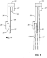
- FIG. 4 An end view of the comb is shown in FIG. 4 .
- the difference in height between the forward tabs 25 and the rear tabs 27 is more clearly visible in FIG. 4 .
- Each of the eight tabs is flat and parallel to the forward face 26 and rear face 27 of the comb. The tabs thus leave gaps 29, 30 to accommodate the two plates of the cassette.
- FIG. 5 shows the comb in place on the cassette, with the front plate 13 and the back plate 14 indicated.
- FIGS. 6 and 7 A variation on the comb of FIGS. 1 through 5 is shown in FIGS. 6 and 7 .
- the comb and hooks combination is divided into two parts, shown separately in FIG. 6 and together in FIG. 7 where they are also shown in place on a cassette.
- the comb itself 31 with its downwardly extending teeth 32 constitutes the first part, and an attachment 33 that contains the forward tabs 34 and the rear tabs 35 constitute the second part.
- the attachment 33 rests on the top of the comb 31, with the tabs 34, 35 extending down the front and rear faces of the com, the tabs 34, 35 being spaced widely enough apart to accommodate both the comb and the cassette.
- the comb 31, attachment 33, and the upper edge of the cassette 36 are shown assembled in FIG. 7 .
- the comb can be made of moldable or machinable materials, examples of which are polycarbonate, acrylic, and polytetrafluoroethylene.
- the gaps 29, 30 are sized to form a close but loose fit, rather than a friction fit. The appropriate fit will be sufficiently loose to allow manual placement of the tabs over the upper edges of the plates 13, 14 and removal of the comb once the gel is cast. The fit is a sufficiently close one however to prevent and significant bowing of the plates upon pressure from a swelling gel.
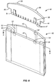
- FIG. 8 depicts a comb 41 posed above a slab gel cassette 42 into which the comb will be lowered before the gel-forming solution has been polymerized into a gel.
- the outer edges 43, 44 of the comb are shaped to rest on the lateral sides of the cassette 42, and specifically in this case on the upper ends 45, 46 of the spacers, while the teeth 47 of the comb extend into the gel cavity between the spacers and the front and back plates 49, 50.
- the front and back plates each have grooves 51, 52, 53, 54 on their inward-facing surfaces
- the comb 41 has ridges 55, 56, 57, 58 whose cross sections have profiles that are complementary to the grooves 51, 52, 53, 54 and whose locations on the comb surface directly face the locations of the grooves.
- the ridges will slide into and along the grooves, and the teeth 47 will extend below the ridges and grooves.
- the result is a tongue-and-groove construction with undercuts to prevent the tongue from leaving the groove other than by sliding out of the open end of the groove.
- the ridges and grooves terminate at a level above the teeth, thereby allowing the gel being cast in the cavity to have flat forward and rear surfaces.
- the ridges and grooves have trapezoidal profiles, causing them to interlock and thereby fix the distance between the forward and rear plates 49, 50 of the cassette, and preventing these plates from bowing outward along their top edges as the gel between them swells.
- a single ridge on each side of the comb and a single correspondingly placed groove on each plate of the cassette can achieve a similar result, as can three or more paired ridges and grooves on each side. Nor is the same number required on both sides.
- the ridge or other protrusion can be on the cassette plates and the grooves on the comb.
- the trapezoidal profiles can also be replaced by any other profiles that have serve an interlocking function. Interlocking profiles in general will be readily apparent to those of skill in the art.
- plastic plates are those residing in the construction of the plates themselves.
- One such option is to use a composite material that is more rigid than the plastic conventionally used.
- the plastic most commonly used in the prior art is polycarbonate, and as noted above, one or both of these plates are typically less than 2.0mm, most commonly about 1.8mm to about 1.9mm, in thickness per plate. Greater rigidity can be achieved by using plates that are substantially thicker, such as for example about 3.0mm or greater, or from about 3.0mm to about 10.0mm, or from about 3.0mm to about 5.0mm.
- Another option is to use a reinforced plastic, such as a glass-filled plastic.
- Glass-filled polycarbonate sheets containing from about 10% to about 30% glass are examples, the sheet thicknesses being somewhat greater, such as by 1.0mm to 3.00mm or more, than those of cassettes formed of non-filled plastic.
- a third option is to use plastic plates that are ribbed for structural reinforcement.
- a rib on the outside surface of the plate preferably a rib running parallel to the open edge of the cassette cavity, can lessen or eliminate any tendency of the plate to bow outward. Any number of such ribs can be used, and two or more ribs that are parallel to each other can be particularly effective. Internal supporting ribs between the two plates can also be used.
- Such ribs can take the form of webs spaced apart along the top edge of the gel cavity, the bottom edge, or both, with opening between the webs to allow access to electrode buffers.
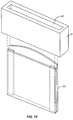
- FIG. 10 depicts such a box 61 poised above a cassette 62.
- the box 61 is hollow and open at the top and bottom to enable the user or manufacturer to slide the box over the cassette.
- the hollow center 63 of the box is long and narrow to contact the two flat plastic plates of the cassette, and the walls of the box are rigid enough to prevent any outward bowing of the flat plates of the cassette.
- a similar result can be achieved with a shrink-wrap type enclosure, i.e., a thick plastic film that tightly encloses the cassette after being first heated to allow the wrap to be stretched and then reheated after it is placed over the cassette to allow the wrap to return to its original unexpanded condition.
- the gel can be cast in subatmospheric pressure, for example, and sealed in an air-tight enclosure while the gel is at the subatmospheric pressure.
- the gel can be cast at atmospheric pressure, then reduced in pressure to a subatmospheric pressure before sealing. In either case, sealing can be done at any time before significant swelling of the gel occurs.
- the cassette once sealed can then be stored in atmospheric pressure. The pressure differential between the atmospheric pressure surrounding the sealed cassette and the subatmospheric pressure inside the seal will then counterbalance any rise increase in pressure within the cassette due to swelling of the gel.
- the air-tight enclosure can be shrink-wrapped over the cassette.
- Suitable sub-atmospheric pressures are those that are about 10 psi (absolute) (69 kilopascals) or less, or from about 0.5 psi to about 10 psi (3.5 to 69 kilopascals), or from about 0.5 psi to about 5 psi (3.5 to 35 kilopascals).
- Outward bowing of the plates can also be prevented at the bottom edge of the plates, i.e., the edge opposite the edge where the samples are loaded. Bowing or warping of the cassette in this region can occur for the same reasons as bowing near the top of the cassette, especially when the bottom of the cassette is open to expose the gel to a lower buffer solution. Means of reducing or eliminating bowing at or near the upper edge can also be applied to prevent bowing at or near the lower edge, with the exception of combs with hook-like projections.
Landscapes
- Health & Medical Sciences (AREA)
- Life Sciences & Earth Sciences (AREA)
- Molecular Biology (AREA)
- Chemical & Material Sciences (AREA)
- Chemical Kinetics & Catalysis (AREA)
- Electrochemistry (AREA)
- Physics & Mathematics (AREA)
- Analytical Chemistry (AREA)
- Biochemistry (AREA)
- General Health & Medical Sciences (AREA)
- General Physics & Mathematics (AREA)
- Immunology (AREA)
- Pathology (AREA)
- Sampling And Sample Adjustment (AREA)
- Apparatus Associated With Microorganisms And Enzymes (AREA)
- Investigating Or Analysing Biological Materials (AREA)
Description
- This invention resides in the field of electrophoresis performed in slab gels. In particular, this invention relates to slab gel cassettes in which the slab gels are retained in enclosures and often stored in buffer solutions until ready for use.
- When a slab gel and the cassette (i.e., the flat-plate enclosure) in which it is cast are immersed in a buffer solution for packaging or storage purposes, the gel tends to absorb water from the buffer solution over time. This uptake of water causes swelling of the gel, and the swelling causes the gel to exert pressure on the plates of the cassette. The pressure causes the plates to bow outward, with the pore size of the gel becoming greater at the center of the gel compared to the edges. When samples are loaded onto the gel and electrophoresis is performed, this variation in pore size causes the solute bands from the sample to migrate faster at their centers, producing an effect on the shapes of the bands known as a "smiling" effect, which increases as the bands migrate greater distances through the gel. This makes reading of the gels difficult and lowers reproducibility and accuracy.
- Cassettes that are particularly susceptible to distortion are those in which one or both of the flat plates is made of plastic, and often plastic that is approximately 2.0mm or less in thickness. While cassettes are available in which one or both plates are made of glass, cassettes in which both plates are plastic offer certain advantages, including ease of manufacture of the plates themselves and ease of sealing the plates to each other along their edges, typically by sonic welding, with appropriate spacers to fix the thickness of the cavity. Electrophoresis "cells" in which the cassettes are placed and that contain electrodes and appropriate electrical connections for imposing an electrical potential along the lengths of the gels are often designed for cassettes of particular sizes which impose an upper limit on the thickness of the cassette walls. Many cassettes are susceptible to distortion for this reason as well.
- Another problem that arises in slab gel cassettes is one involving the formation of wells along the upper edge of the gel that are used for the loading of samples onto the gel. These wells are formed by the use of a well-forming insert commonly known as a "comb," which is a bar with dentiform projections, or "teeth," along one longitudinal edge of the bar. The comb is placed on the cassette prior to the casting (polymerization) of the gel with the teeth extending into the cavity to form the wells as the polymerization reaction proceeds. Ideally, the thickness of each of the teeth is equal to the gap width between the flat plates of the gel, so that the final gel will extend upwards between adjacent teeth but not into regions between the fronts or backs of individual teeth and the cassette walls where gel material can make it difficult to remove the comb from the cassette and expose the wells. In practical usage, however, avoidance of gel material in these regions is difficult to achieve, and is more so when these regions widen. The comb is also typically made of a material that inhibits polymerization at its surface, thereby preventing the polymerized gel from adhering to the comb. This is of value since adhesion of the gel makes it difficult to remove the comb without damaging the partitions in the gel that separate the wells. The comb material also inhibits polymerization in the spaces between the teeth of the comb and the cassette plates, but tends to lose its ability to do this when these spaces widen or when combs are used that are off-specification or otherwise thinner than expected. Polymerization in these spaces can also occur when too much polymerization catalyst is present or when copper is present in the monomer solution at a high concentration. The formation of gel material in these spaces is known as "webbing," and interferes with the loading of the samples.
- Disclosures of combs designed for use in the casting of electrophoresis gels appear in the following United States patents:
Sugimoto et al. (Fuji Photo Film Co., Ltd.) US 4,883,577, Nov. 28, 1989 ;Bambeck et al. US 4,909,918, March 20, 1990 ;Chu et al. (Bio-Rad Laboratories, Inc.) US 5,073,246, Dec. 17, 1991 , which discloses an enclosure for a slab gel for electrophoretic separations, said enclosure comprising in particular first and second plates and first and second spacer strips for placement between said plates to define an open space for said slab gel;Bettencourt et al. (Bio-Rad Laboratories, Inc.) US 5,164,065, Nov. 17, 1992 ;Chu et al. (Bio-Rad Laboratories, Inc.) US 5,284,565, Feb. 8, 1994 ;Steiner et al. (Pharmacia Biotech) US 5,843,295, Dec. 1, 1998 ;Selby et al. (The Perkin-Elmer Corporation) US 5,993,628 (Nov. 30, 1999 );Scott (C.B.S. Scientific Co., Inc.) US 6,139,709, Oct. 31, 2000 ;Latham (Bio-Rad Laboratories, Inc.) US 7,588,673 B2, Sep. 15, 2009 ; andPerez et al. (Bio-Rad Laboratories, Inc.) US 7,658,827 B2, Feb. 9, 2010 . - The present invention is defined in the claims. The slab gels in these descriptions are retained in a slab-shaped cavity inside a plastic-walled gel enclosure, referred to in the industry as a "cassette." The cavity has at least one open side through which a monomer solution from which the gel will be cast can be introduced. The structure of the enclosure, or of parts that are either joined to the enclosure or otherwise used in conjunction with the enclosure, help impose a maximum dimension on the width of the cavity, i.e., the gap width between the two plastic plates, during gel casting and storage. When in storage, the gel and cassette are typically maintained in contact with a storage buffer, which exacerbates the swelling problem. By imposing a maximum dimension on the cavity width, the tendencies of the cavity to expand due to pressure generated inside the cavity by swelling of the gel are offset, and the gap width between the plates is inhibited or prevented entirely from increasing. The structural features that achieve this result reside in the comb, which is a bar with dentiform projections, and in additional components that are attached onto or generally used in conjunction with the comb. An alternative means of achieving dimensional stability is by lowering the pressure inside the gel cavity once the monomer solution has been placed inside the cavity or soon after the gel has been cast, and maintaining the reduced pressure level until a short period of time before the cassette is used in an electrophoresis experiment.
- Included among the variety of structural features disclosed herein to offset the swelling of the gel and thereby prevent outward bowing of the cassette plates are removable attachments to the cassette or to the comb used in conjunction with the cassette, features (removable or otherwise) that secure the gap width along the upper edge of the gel where samples are introduced and where the sample wells reside, and features (removable or otherwise) that secure the gap width along the lower edge of the gel, which is in the downstream direction of the migration of the sample solutes during electrophoresis.
- A comb is disclosed herein that, in addition to serving its function of forming a row of sample wells in an electrophoresis gel within the cassette, also prevents outward bowing of the cassette plates when the tendency of the gel to swell causes pressure to be exerted against the plates. In addition to its teeth, the comb has hook-like projections extending from both its front and back surfaces that engage the two plates, respectively, of the cassette, at the upper edges of the plates. These projections prevent the plates from bowing out at these edges and at the areas adjacent to these edges. The hook-like projections can have hook-shaped profiles or any other shape or profile, such as flat tabs, for example, that will engage the plates and help them resist bowing. The comb contains two or more hook-like projections on each side. Best results will generally be achieved when the projections engage the centers of the upper edges of the plates, or locations along the upper edges on both sides of the centers in a symmetrical arrangement around the centerline of each plate. Two or more projections can be included on a given side of the comb, sufficiently spaced apart to produce support along the width of the plate. A plurality of projections on either side of the comb, evenly spaced along the comb will provide still greater assurance that the cassette plates remain parallel and are restrained from bowing. In certain embodiments of the design, other features are included to accommodate particular cassettes. For cassettes with plates of unequal height, for example, the hook-like projection(s) on one side of the comb will be higher than the hook-like projection(s) on the other side to match the different heights of the cassette plates.
- In certain other embodiments of the invention, the comb and cassette have interlocking features on their surfaces that are readily engaged and disengaged by simply inserting and removing the comb. The interlock can be achieved by the profiles of the features, such as for example, tabs, knobs, or ridges on one surface and complementary grooves on the other, each the profiles such that the features are engaged either by pressing or snapping together or by sliding one inside the other.
- Other features and variations will be apparent to those of skill in the art, and some are shown and described below.
-
-
FIG. 1 is a perspective view of a combination of a comb and a slab gel cassette as an illustration of one embodiment of the present invention, separated from each other to expose the contacting parts. -
FIG. 2 is a front view of the comb ofFIG. 1 . -
FIG. 3 is a top view of the comb ofFIG. 1 . -
FIG. 4 is an end view of the comb ofFIG. 1 . -
FIG. 5 is the same view of the comb asFIG. 4 but shown in position over the front and back plates of the cassette. -
FIG. 6 is an end view of a comb and attachment that together serve as an alterative to the comb ofFIG. 1 . -
FIG. 7 is an end view of the comb and attachment ofFIG. 6 in place on a cassette. -
FIG. 8 is a perspective view of a combination of a comb and a slab gel cassette, different from those of the preceding figures, as an illustration of a further embodiment of the present invention. The comb and cassette are separated from each other to expose the contacting parts. -
FIG. 9 is a cross section view of the comb and cassette ofFIG. 8 , along the line 9-9 ofFIG. 8 . -
FIG. 10 is a perspective view of a combination of a slab gel cassette and an outer rigidifying enclosure, separated from each other. - While the devices and methods covered by the claims herein are susceptible of a wide range of embodiments and implementations, a full understanding of the invention as a whole will be readily gained from descriptions of specific embodiments. Several such embodiments are described below, and certain of these are illustrated in the Figures.
- As noted above, one such embodiment is a comb of specialized construction to include features for engaging the upper edges of the plastic plates of the cassette.
FIG. 1 depicts such acomb 11 poised above aslab gel cassette 12 from which the comb has been removed following the casting of a gel in the cassette. Both thecomb 11 and thecassette 12 are oriented vertically, as they will be during use. Thecassette 12 is formed from two flat plates, one of which is afront plate 13 and the other aback plate 14, sealed and spaced apart at their two side edges byspacers spacers back plate 14 is taller than thefront plate 13, as is common among slab gel cassettes to facilitate the retention of an upper buffer solution in contact with the upper edge of the gel. Theupper edge 17 of the back plate is arched while theupper edge 18 of the front plate is straight and horizontal. The gel is shown in dashed lines and contains a series ofrectangular indentations 19 along its upper edge serving as sample wells, adjacent wells being separated bypartitions 21 which are cast as part of the gel. In the conventional manner, the sample wells are formed by theteeth 22 on thecomb 11. The number of teeth shown, and hence the number of sample wells, is twelve, but this is only an example; the number can vary widely. - The
comb 11 is abar 23 with an archedupper edge 24 to match the archedupper edge 17 of theback plate 14 of the cassette. A row of sixtabs 25 extends forward from, parallel to, and uniformly spaced from, theforward face 26 of the bar to serve as the forward hook-like projections. Similarly, twotabs 27 extend rearward from, parallel to, and uniformly spaced from, the rear face (not visible) of the bar to serve as the rear hook-like projections. The comb is also shown in a front view inFIG. 2 and in a top view inFIG. 3 . Therear face 28 is indicated inFIG. 3 . - An end view of the comb is shown in
FIG. 4 . The difference in height between theforward tabs 25 and therear tabs 27 is more clearly visible inFIG. 4 . Each of the eight tabs is flat and parallel to theforward face 26 andrear face 27 of the comb. The tabs thus leavegaps FIG. 5 shows the comb in place on the cassette, with thefront plate 13 and theback plate 14 indicated. - A variation on the comb of
FIGS. 1 through 5 is shown inFIGS. 6 and 7 . In this variation, the comb and hooks combination is divided into two parts, shown separately inFIG. 6 and together inFIG. 7 where they are also shown in place on a cassette. The comb itself 31 with its downwardly extendingteeth 32 constitutes the first part, and anattachment 33 that contains theforward tabs 34 and therear tabs 35 constitute the second part. Theattachment 33 rests on the top of thecomb 31, with thetabs tabs comb 31,attachment 33, and the upper edge of thecassette 36 are shown assembled inFIG. 7 . - The comb can be made of moldable or machinable materials, examples of which are polycarbonate, acrylic, and polytetrafluoroethylene. The
gaps plates - A further alternative to the comb and cassette combination of the preceding figures is that shown in
FIGS. 8 and9 .FIG. 8 , likeFIG. 1 , depicts acomb 41 posed above aslab gel cassette 42 into which the comb will be lowered before the gel-forming solution has been polymerized into a gel. The outer edges 43, 44 of the comb are shaped to rest on the lateral sides of thecassette 42, and specifically in this case on the upper ends 45, 46 of the spacers, while theteeth 47 of the comb extend into the gel cavity between the spacers and the front andback plates grooves comb 41 hasridges grooves teeth 47 will extend below the ridges and grooves. The result is a tongue-and-groove construction with undercuts to prevent the tongue from leaving the groove other than by sliding out of the open end of the groove. The ridges and grooves terminate at a level above the teeth, thereby allowing the gel being cast in the cavity to have flat forward and rear surfaces. As shown in the cross section ofFIG. 9 , the ridges and grooves have trapezoidal profiles, causing them to interlock and thereby fix the distance between the forward andrear plates - While two ridges (or tongues with undercut) are placed on each surface of the comb, with the corresponding grooves occupying complementary positions on the plates of the cassette, the number and placement can vary and are not critical provided that they prevent the plates from bowing outward. A single ridge on each side of the comb and a single correspondingly placed groove on each plate of the cassette can achieve a similar result, as can three or more paired ridges and grooves on each side. Nor is the same number required on both sides. As a further alternative, the ridge or other protrusion can be on the cassette plates and the grooves on the comb. The trapezoidal profiles can also be replaced by any other profiles that have serve an interlocking function. Interlocking profiles in general will be readily apparent to those of skill in the art.
- Other options for preventing outward bowing of the plastic plates are those residing in the construction of the plates themselves. One such option is to use a composite material that is more rigid than the plastic conventionally used. The plastic most commonly used in the prior art is polycarbonate, and as noted above, one or both of these plates are typically less than 2.0mm, most commonly about 1.8mm to about 1.9mm, in thickness per plate. Greater rigidity can be achieved by using plates that are substantially thicker, such as for example about 3.0mm or greater, or from about 3.0mm to about 10.0mm, or from about 3.0mm to about 5.0mm. Another option is to use a reinforced plastic, such as a glass-filled plastic. Glass-filled polycarbonate sheets containing from about 10% to about 30% glass are examples, the sheet thicknesses being somewhat greater, such as by 1.0mm to 3.00mm or more, than those of cassettes formed of non-filled plastic. A third option is to use plastic plates that are ribbed for structural reinforcement. A rib on the outside surface of the plate, preferably a rib running parallel to the open edge of the cassette cavity, can lessen or eliminate any tendency of the plate to bow outward. Any number of such ribs can be used, and two or more ribs that are parallel to each other can be particularly effective. Internal supporting ribs between the two plates can also be used. Such ribs can take the form of webs spaced apart along the top edge of the gel cavity, the bottom edge, or both, with opening between the webs to allow access to electrode buffers.
- Further options are those involving the use of external cages, bars, clamps, plates, and the like, that are attached to or otherwise pressed against the outer surfaces of the plastic plates that form the cassette. These external fixtures can be attached, applied, or held in place during casting of the gels, storage and shipment, or both, and removed shortly prior to use of the cassette in an electrophoresis experiment. A box, grid, or cage of rigid material such as metal, wood, or extra-thick plastic, that can be slid or otherwise placed over the cassette while contacting the outer walls of both cassette plates and readily removed prior to us of the cassette, can be used.
FIG. 10 depicts such a box 61 poised above acassette 62. The box 61 is hollow and open at the top and bottom to enable the user or manufacturer to slide the box over the cassette. Thehollow center 63 of the box is long and narrow to contact the two flat plastic plates of the cassette, and the walls of the box are rigid enough to prevent any outward bowing of the flat plates of the cassette. A similar result can be achieved with a shrink-wrap type enclosure, i.e., a thick plastic film that tightly encloses the cassette after being first heated to allow the wrap to be stretched and then reheated after it is placed over the cassette to allow the wrap to return to its original unexpanded condition. - Still further options are those involving the condition in which the gel is cast and the cassette is stored. The gel can be cast in subatmospheric pressure, for example, and sealed in an air-tight enclosure while the gel is at the subatmospheric pressure. Alternatively, the gel can be cast at atmospheric pressure, then reduced in pressure to a subatmospheric pressure before sealing. In either case, sealing can be done at any time before significant swelling of the gel occurs. The cassette once sealed can then be stored in atmospheric pressure. The pressure differential between the atmospheric pressure surrounding the sealed cassette and the subatmospheric pressure inside the seal will then counterbalance any rise increase in pressure within the cassette due to swelling of the gel. The air-tight enclosure can be shrink-wrapped over the cassette. Suitable sub-atmospheric pressures are those that are about 10 psi (absolute) (69 kilopascals) or less, or from about 0.5 psi to about 10 psi (3.5 to 69 kilopascals), or from about 0.5 psi to about 5 psi (3.5 to 35 kilopascals).
- Outward bowing of the plates can also be prevented at the bottom edge of the plates, i.e., the edge opposite the edge where the samples are loaded. Bowing or warping of the cassette in this region can occur for the same reasons as bowing near the top of the cassette, especially when the bottom of the cassette is open to expose the gel to a lower buffer solution. Means of reducing or eliminating bowing at or near the upper edge can also be applied to prevent bowing at or near the lower edge, with the exception of combs with hook-like projections.
Claims (15)
- A device (11) for insertion between a pair of parallel flat casting plates (13, 14) to form a row of sample wells (19) in an electrophoresis slab gel as said gel is cast between said plates (13, 14), said device (11) comprising:a flat bar (23) having a forward face (26), a rear face (28), and a longitudinal edge, a row of dentiform projections (22) along said longitudinal edge, characterized in that said device further comprises first hook means (25) projecting forward from said forward face (26), andsecond hook means (27) projecting rearward from said rear face (28), said first (25) and second (27) hook means shaped to hold said casting plates (13, 14) parallel to each other and at a fixed distance from each other with said dentiform projections (22) between said casting plates (13, 14).
- The device (11) of claim 1 wherein one of said first hook means (25) and said second hook means (27) is a row of tabs parallel to and uniformly spaced from said forward face (26).
- The device of claim 1 wherein said first hook means (25) is a first row of tabs parallel to and uniformly spaced from said forward face (26), and said second hook means (27) is a second row of tabs parallel to and uniformly spaced from said rear face (28).
- The device of claim 1 wherein, when said forward (26) and rear (28) faces are vertical, said second hook means (27) is higher than said first hook means (25).
- Apparatus for casting an electrophoresis slab gel, said apparatus comprising:a gel enclosure (12) defining a rectangular slab-shaped cavity with opposing upper and lower edges and opposing side edges, said gel enclosure (12) comprising first and second flat plastic plates (13, 14) and means for securing (25, 27) said plates (13, 14) together along said side edges of said cavity with a gap of preselected width between said plastic plates (13, 14), andthe device (11) of any one of claims 1 to 4 on or attachable to said gel enclosure (12) for holding said plastic plates (13, 14) immobile along said upper edge and thereby maintaining said preselected width along said upper edge upon exposure to pressure generated inside said cavity when a slab gel resides in said cavity and exerts an outward force against said plastic plates (13, 14).
- The apparatus of claim 5 further comprising a well-forming insert (11) comprising a flat bar (23) having a longitudinal edge and a row of dentiform projections (22) along said longitudinal edge, said projections (22) sized to fit inside said slab-shaped cavity.
- The apparatus of claim 6 wherein said flat bar (23) has a forward face (26) and a rear face (28) and said means for holding said plastic plates immobile along said upper edge comprise first hook means (25) projecting forward from said forward face (26) and second hook means (27) projecting rearward from said rear face (28), said first (25) and second (27) hook means shaped to hook over said first (13) and second (14) plastic plates, respectively.
- The apparatus of claim 6 wherein said means for holding said plastic plates (13, 14) immobile along said upper edge comprise an attachment removably joinable to said well-forming insert (11), said attachment comprising first (25) and second (27) hook means oriented such that when said attachment is joined to said well-forming insert (11), said first hook means (25) hooks over said first plastic plate (13) and said second hook means (27) hooks over said second plastic plate (14).
- The apparatus of claims 7 or 8 wherein one of said first hook means (25) and said second hook means (27) is a row of tabs parallel to said row of dentiform projections (22).
- The apparatus of claims 7 or 8 wherein said first hook means (25) is a first row of tabs parallel to said row of dentiform projections (22) and said second hook means (27) is a second row of tabs parallel to said row of dentiform projections (22).
- The apparatus of claims 7 or 8 wherein said first (13) and second (14) plastic plates have upper edges (17, 18), and when said first (13) and second (14) plastic plates are vertical, said upper edge (17) of said second plastic plate (14) is higher than said upper edge (18) of said first plastic plate (13), and said second hook means (27) is higher than said first hook means (25).
- A method for casting a slab gel with sample wells (19) for electrophoresis, said method comprising:(a) placing a gel-forming monomer solution in a slab-shaped cavity having an open side according to the apparatus of any one of claims 5-11;(b) polymerizing said monomer solution to form said gel; and(c) either during or after (b), imposing a force on said plastic plates (13, 14) to oppose any outward force against said plastic plates (13, 14) caused by pressure generated inside said cavity by a slab monomer solution or said gel.
- The method of claim 12 wherein step (c) comprises(i) placing said gel enclosure (12) in an outer enclosure that contacts outer surfaces of said plastic plates (13, 14) and that is substantially more rigid than said plastic plates (13, 14); or(ii) placing a stack of said gel enclosures (12) in an outer enclosure that contacts outer surfaces of outermost plastic plates (13, 14) of said stack and that is substantially more rigid than said plastic plates (13, 14).
- The method of claim 12 further comprising inserting a well-forming insert (11) in said open side of said slab-shaped cavity, prior to step (b), said well-forming insert (11) comprising a flat bar (23) having a longitudinal edge and a row of dentiform projections (22) along said longitudinal edge, said projections sized to fit inside said slab-shaped cavity.
- A method for casting a slab gel with sample wells for electrophoresis, said method comprising:(a) placing a gel-forming monomer solution in a slab-shaped cavity having an open side according to the apparatus of any one of claims 5-11, said cavity being in an enclosure (12) comprising first (13) and second (14) flat plastic plates with a gap of preselected width between said plastic plates (13, 14);(b) polymerizing said monomer solution to form said gel; and(c) either during or after (b), imposing a subatmospheric pressure on said cavity and sealing said enclosure (12) to maintain said subatmospheric pressure.
Applications Claiming Priority (3)
| Application Number | Priority Date | Filing Date | Title |
|---|---|---|---|
| US201161446347P | 2011-02-24 | 2011-02-24 | |
| US201261588830P | 2012-01-20 | 2012-01-20 | |
| PCT/US2012/026557 WO2012116297A1 (en) | 2011-02-24 | 2012-02-24 | Dimensional stabilization of slab gel cassettes to prevent distortion caused by swelling gels |
Publications (3)
| Publication Number | Publication Date |
|---|---|
| EP2678671A1 EP2678671A1 (en) | 2014-01-01 |
| EP2678671A4 EP2678671A4 (en) | 2014-12-03 |
| EP2678671B1 true EP2678671B1 (en) | 2020-02-19 |
Family
ID=46721249
Family Applications (1)
| Application Number | Title | Priority Date | Filing Date |
|---|---|---|---|
| EP12750096.5A Active EP2678671B1 (en) | 2011-02-24 | 2012-02-24 | Dimensional stabilization of slab gel cassettes to prevent distortion caused by swelling gels |
Country Status (8)
| Country | Link |
|---|---|
| US (1) | US9234874B2 (en) |
| EP (1) | EP2678671B1 (en) |
| JP (1) | JP5945284B2 (en) |
| CN (1) | CN103460033B (en) |
| AU (1) | AU2012222167B2 (en) |
| CA (1) | CA2827234A1 (en) |
| SG (1) | SG192792A1 (en) |
| WO (1) | WO2012116297A1 (en) |
Families Citing this family (21)
| Publication number | Priority date | Publication date | Assignee | Title |
|---|---|---|---|---|
| EP2470691B1 (en) | 2009-08-24 | 2014-12-03 | Life Technologies Corporation | Electrophoresis gel cassette and comb |
| USD719277S1 (en) | 2010-08-24 | 2014-12-09 | Life Technologies Corporation | Electrophoresis wedge-well comb |
| WO2014150275A1 (en) | 2013-03-15 | 2014-09-25 | Bio-Rad Laboratories, Inc. | Polyacrylamide gels for rapid casting, blotting, and imaging, with storage stability |
| CN106133514A (en) * | 2014-03-31 | 2016-11-16 | 夏普株式会社 | Separation medium cartridge for sample separation and adsorption and analysis device for sample separation and adsorption |
| KR200480488Y1 (en) | 2014-04-04 | 2016-05-31 | (주)바이온라이프사이언스 | Multi Comb |
| USD806894S1 (en) | 2015-03-19 | 2018-01-02 | Life Technologies Corporation | Electrophoresis comb with wedge-shaped teeth |
| USD792603S1 (en) | 2015-11-13 | 2017-07-18 | Life Technologies Corporation | Rig for electrophoresis gel casting |
| USD851779S1 (en) * | 2015-11-13 | 2019-06-18 | Life Technologies Corporation | Electrophoresis cassette with sample loading guide |
| EP3374764B1 (en) * | 2015-11-13 | 2024-01-24 | Life Technologies Corporation | Preparation of electrophoresis gels, and related devices, systems, and methods |
| USD816865S1 (en) | 2015-11-13 | 2018-05-01 | Life Technologies Corporation | Cassette support base for electrophoresis gel casting |
| USD859688S1 (en) * | 2015-11-13 | 2019-09-10 | Life Technologies Corporation | Electrophoresis slab gel sample loading guide |
| USD849963S1 (en) * | 2015-11-13 | 2019-05-28 | Life Technologies Corporation | Electrophoresis gel cassette |
| USD856528S1 (en) | 2015-11-13 | 2019-08-13 | Life Technologies Corporation | Cassette clamp for electrophoresis gel casting |
| USD861915S1 (en) * | 2017-09-13 | 2019-10-01 | Thermo Fisher Scientific Baltics Uab | Cassette assembly for electrophoresis gel |
| JP7072850B2 (en) * | 2018-06-08 | 2022-05-23 | 国立大学法人広島大学 | Slab-type electrophoresis gel and its use |
| USD919835S1 (en) | 2020-02-10 | 2021-05-18 | Thermo Fisher Scientific Baltics Uab | Cassette assembly for electrophoresis gel |
| US12292408B2 (en) * | 2020-07-13 | 2025-05-06 | Life Technologies Corporation | Electrophoresis and electrotransfer devices, systems, and methods |
| JP2025517160A (en) * | 2022-05-10 | 2025-06-03 | イー・エム・デイー・ミリポア・コーポレイシヨン | Sample well comb mask for photopolymerized electrophoresis gels |
| USD1074358S1 (en) * | 2023-02-24 | 2025-05-13 | Emd Millipore Corporation | Electrophoretic gel comb |
| WO2026035567A1 (en) * | 2024-08-05 | 2026-02-12 | Life Technologies Corporation | Electrophoresis cassette and comb |
| CN119780201B (en) * | 2025-01-07 | 2026-06-19 | 江苏姜曲海猪种业有限公司 | Detection device for preparing recombinant adenovirus for expressing African swine fever protein |
Family Cites Families (43)
| Publication number | Priority date | Publication date | Assignee | Title |
|---|---|---|---|---|
| US3842020A (en) | 1971-11-08 | 1974-10-15 | Dow Chemical Co | Method of expanding a resole resin containing expandable thermoplastic microspheres and product obtained therefrom |
| US3842202A (en) * | 1972-11-06 | 1974-10-15 | Levy M & Co Inc | Combination of a transmissive diffractive phase-grating and a television picture-tube in operative juxtaposition to each other |
| US3881683A (en) * | 1973-11-29 | 1975-05-06 | American Optical Corp | Gasket for lens mold |
| JPS5525U (en) * | 1979-01-05 | 1980-01-05 | ||
| US4522768A (en) * | 1979-05-11 | 1985-06-11 | Sola Products Limited | Casting gasket assembly and method for casting lenses therefrom |
| US4279401A (en) * | 1980-05-30 | 1981-07-21 | American Optical Corporation | Apparatus and method for making cast ophthalmic lenses |
| US4560459A (en) * | 1984-02-21 | 1985-12-24 | Hoefer Scientific Instruments | Vertical gel sandwich for use in electrophoresis and method therefor |
| US4663015A (en) | 1985-09-30 | 1987-05-05 | Bio-Rad Laboratories, Inc. | Electrophoresis apparatus for nucleic acid sequencing |
| JPS6385348A (en) * | 1986-09-29 | 1988-04-15 | Shimadzu Corp | sampling unit |
| US5073246A (en) * | 1990-05-16 | 1991-12-17 | Bio-Rad Laboratories, Inc. | Slab electrophoresis system with improved sample wells and cooling mechanism |
| JPH0526845A (en) * | 1991-07-22 | 1993-02-02 | Hitachi Ltd | Gel electrophoresis tank for light detection |
| US5284565A (en) * | 1992-12-23 | 1994-02-08 | Bio-Rad Laboratories, Inc. | Sample well insert with wedge-shaped profile for ultra-thin slab gels in electrophoresis |
| US5433837A (en) * | 1993-08-27 | 1995-07-18 | E. I. Du Pont De Nemours And Company | Gel cassette for enhanced electrophoretic separation and processes for the preparation thereof |
| US5384025A (en) * | 1994-03-07 | 1995-01-24 | Applied Biosystems, Inc. | Notched spacer for slab-gel electrophoresis |
| US5543097A (en) * | 1994-03-09 | 1996-08-06 | Fang; Ta-Yun | Methods for preparing polyacrylamide gels for electrophoretic analysis |
| NL9500431A (en) * | 1994-09-30 | 1996-05-01 | Ingeny Bv | Gel cassette and electrophoresis device. |
| US5626735A (en) * | 1994-05-26 | 1997-05-06 | Bio-Rad Laboratories, Inc. | Electrophoresis slab gel enclosure for gradient gels |
| WO1996009537A1 (en) | 1994-09-19 | 1996-03-28 | Novel Experimental Technology | Plastic mold for electrophoresis gel |
| US5514255A (en) * | 1995-01-25 | 1996-05-07 | Gautsch; James | Vertically stacked trays overflowing liquid congealing into electrophoresis gel, and optional combination spacer-combs between the trays |
| US5618399A (en) * | 1995-01-25 | 1997-04-08 | Gautsch; James W. | Comb elements rotating in position to place selected slit arrays in the gel of an electrophoresis agarose gel tray, particularly as also serve as spacers between stacked trays |
| JP2835426B2 (en) * | 1995-08-02 | 1998-12-14 | 農林水産省農業生物資源研究所長 | Electrophoresis device |
| US5809625A (en) * | 1995-12-15 | 1998-09-22 | Guaranteed Seal System | Apparatus and method for lowering a burial vault and casket |
| US5656145A (en) * | 1996-05-20 | 1997-08-12 | Bio-Rad Laboratories, Inc. | Needle guide for loading samples into a vertical slab gel |
| US5843295A (en) * | 1996-12-19 | 1998-12-01 | Pharmacia Biotech | Gel electrophoresis well-forming and loading-guide comb |
| US5989403A (en) * | 1997-12-12 | 1999-11-23 | Fmc Corporation | Electrophoresis assembly with filling means |
| US5975340A (en) | 1997-12-17 | 1999-11-02 | The Popstraw Company, Llc | Straw and dispensing device for use in a beverage container |
| US5993628A (en) * | 1998-04-17 | 1999-11-30 | The Perkin-Elmer Corporation | Electrophoresis method and apparatus for separating bio-organic molecules |
| US6093301A (en) * | 1998-09-11 | 2000-07-25 | Bio-Rad Laboratories, Inc. | Slab gel cassettes with side openings |
| US6162342A (en) * | 1999-02-12 | 2000-12-19 | Bio-Rad Laboratories, Inc. | Rapid assembly casting system for slab gels |
| US20020096431A1 (en) | 1999-09-01 | 2002-07-25 | Pierre Sevigny | Apparatus for the manufacture of a disposable electrophoresis cassette and method thereof |
| US6436262B1 (en) | 2000-04-24 | 2002-08-20 | Bio-Rad Laboratories, Inc. | Compact cell clamp for slab gel plate assembly |
| AUPR103600A0 (en) * | 2000-10-26 | 2000-11-16 | Life Therapeutics Limited | Improved electrophoresis gel cassette |
| WO2003048754A1 (en) * | 2001-11-30 | 2003-06-12 | Alpenfels William F | Electrophoresis gel assembly and method of assembling the same |
| US6969455B1 (en) * | 2003-01-22 | 2005-11-29 | Joel Helfer | Electrophoresis frame for gel slabs with different thickness holder plates |
| US7749367B2 (en) * | 2003-03-05 | 2010-07-06 | Deming Zhou | Vertical slab gel electrophoresis cell and method therefor |
| JP4424938B2 (en) * | 2003-08-19 | 2010-03-03 | タイテック株式会社 | Microgel cassette for electrophoresis |
| WO2005095940A1 (en) * | 2004-03-31 | 2005-10-13 | Delcon S.R.L. | Cassette for electrophoresis apparatus |
| WO2005098408A1 (en) | 2004-04-01 | 2005-10-20 | C.B.S. Scientific Co., Inc. | Multi function gel electrophoresis and apparatus |
| US7588673B2 (en) * | 2005-09-14 | 2009-09-15 | Bio-Rad Laboratories, Inc. | Electrophoresis cassette with sealing and closure features |
| US7854021B2 (en) | 2007-08-21 | 2010-12-21 | J. Bren & Company, Inc. | Attachable and detachable pocket cover |
| EP2470691B1 (en) * | 2009-08-24 | 2014-12-03 | Life Technologies Corporation | Electrophoresis gel cassette and comb |
| US20110084194A1 (en) * | 2009-09-24 | 2011-04-14 | Dgel Sciences | Cassette for biological analysis and method of making thereof |
| US9061236B2 (en) * | 2012-11-20 | 2015-06-23 | Nanjingjinsirui Science & Technology Biology Corporation | Gel electrophoresis device for loading large sample volumes |
-
2012
- 2012-02-13 US US13/371,667 patent/US9234874B2/en active Active
- 2012-02-24 CA CA2827234A patent/CA2827234A1/en not_active Abandoned
- 2012-02-24 CN CN201280010356.2A patent/CN103460033B/en active Active
- 2012-02-24 EP EP12750096.5A patent/EP2678671B1/en active Active
- 2012-02-24 AU AU2012222167A patent/AU2012222167B2/en not_active Ceased
- 2012-02-24 JP JP2013555606A patent/JP5945284B2/en not_active Expired - Fee Related
- 2012-02-24 WO PCT/US2012/026557 patent/WO2012116297A1/en not_active Ceased
- 2012-02-24 SG SG2013062146A patent/SG192792A1/en unknown
Non-Patent Citations (1)
| Title |
|---|
| None * |
Also Published As
| Publication number | Publication date |
|---|---|
| JP2014506681A (en) | 2014-03-17 |
| SG192792A1 (en) | 2013-09-30 |
| US20130056909A1 (en) | 2013-03-07 |
| WO2012116297A1 (en) | 2012-08-30 |
| AU2012222167B2 (en) | 2015-07-30 |
| US9234874B2 (en) | 2016-01-12 |
| JP5945284B2 (en) | 2016-07-05 |
| CN103460033B (en) | 2016-08-10 |
| CN103460033A (en) | 2013-12-18 |
| EP2678671A1 (en) | 2014-01-01 |
| AU2012222167A1 (en) | 2013-08-29 |
| CA2827234A1 (en) | 2012-08-30 |
| EP2678671A4 (en) | 2014-12-03 |
Similar Documents
| Publication | Publication Date | Title |
|---|---|---|
| US9234874B2 (en) | Dimensional stabilization of slab gel cassettes to prevent distortion caused by swelling gels | |
| JP2620504B2 (en) | Sample well insert for forming wedge-shaped wells in ultra-thin slab gel for electrophoresis | |
| US20240192165A1 (en) | Electrophoresis gel cassette and comb | |
| US4954236A (en) | Apparatus and method for gel casting and electrophoresis in a single enclosure | |
| KR20190095107A (en) | Flow Cell Cartridge with Floating Seal Bracket | |
| EP0334615B1 (en) | Electrophoresis apparatus | |
| JP2014506681A5 (en) | ||
| US5938906A (en) | Horizontal gel electrophoresis casting cassette | |
| CA2362042C (en) | Rapid assembly casting system for slab gels | |
| JPS62125339A (en) | Holding sheet for information recording carrier | |
| US5569369A (en) | Cassette for high resolution gel electrophoresis | |
| CA2426563A1 (en) | Cassette assembly for electrophoresis gels | |
| US4618408A (en) | Casting apparatus for electrophoretic gel tray | |
| US5358214A (en) | Mold for concrete modular precastings | |
| US12261068B2 (en) | Wafer support member and method of manufacturing a wafer support member | |
| WO2014088948A1 (en) | Combless gel electrophoresis device | |
| CN210900926U (en) | A kind of comb and beehive | |
| CN112206659A (en) | Integrated polyacrylamide gel electrophoresis device | |
| KR910003231Y1 (en) | Rice cake | |
| JP2594077Y2 (en) | Battery case lid for storage battery | |
| AU2002210242B2 (en) | Cassette assembly for electrophoresis gels | |
| US874841A (en) | Storage-battery plate. | |
| SU966578A1 (en) | Device for electrophoresis on vertical gel plate | |
| JPH0641934B2 (en) | Two-dimensional electrophoresis | |
| JPS63307348A (en) | Glass plate assembly for preparation of gel of slag type electrophoretic device and electrophoretic analysis method using said assembly |
Legal Events
| Date | Code | Title | Description |
|---|---|---|---|
| PUAI | Public reference made under article 153(3) epc to a published international application that has entered the european phase |
Free format text: ORIGINAL CODE: 0009012 |
|
| 17P | Request for examination filed |
Effective date: 20130829 |
|
| AK | Designated contracting states |
Kind code of ref document: A1 Designated state(s): AL AT BE BG CH CY CZ DE DK EE ES FI FR GB GR HR HU IE IS IT LI LT LU LV MC MK MT NL NO PL PT RO RS SE SI SK SM TR |
|
| RIN1 | Information on inventor provided before grant (corrected) |
Inventor name: LATHAM, MATTHEW Inventor name: WALKER, JOHN Inventor name: PANATTONI, CORY Inventor name: KIMMEL, KARA |
|
| DAX | Request for extension of the european patent (deleted) | ||
| RIN1 | Information on inventor provided before grant (corrected) |
Inventor name: KIMMEL, KARA Inventor name: LATHAM, MATTHEW Inventor name: WALKER, JOHN Inventor name: PANATTONI, CORY |
|
| A4 | Supplementary search report drawn up and despatched |
Effective date: 20141030 |
|
| RIC1 | Information provided on ipc code assigned before grant |
Ipc: G01N 27/447 20060101AFI20141024BHEP Ipc: G01N 27/26 20060101ALI20141024BHEP |
|
| STAA | Information on the status of an ep patent application or granted ep patent |
Free format text: STATUS: EXAMINATION IS IN PROGRESS |
|
| 17Q | First examination report despatched |
Effective date: 20170206 |
|
| GRAP | Despatch of communication of intention to grant a patent |
Free format text: ORIGINAL CODE: EPIDOSNIGR1 |
|
| STAA | Information on the status of an ep patent application or granted ep patent |
Free format text: STATUS: GRANT OF PATENT IS INTENDED |
|
| INTG | Intention to grant announced |
Effective date: 20190830 |
|
| GRAS | Grant fee paid |
Free format text: ORIGINAL CODE: EPIDOSNIGR3 |
|
| GRAA | (expected) grant |
Free format text: ORIGINAL CODE: 0009210 |
|
| STAA | Information on the status of an ep patent application or granted ep patent |
Free format text: STATUS: THE PATENT HAS BEEN GRANTED |
|
| AK | Designated contracting states |
Kind code of ref document: B1 Designated state(s): AL AT BE BG CH CY CZ DE DK EE ES FI FR GB GR HR HU IE IS IT LI LT LU LV MC MK MT NL NO PL PT RO RS SE SI SK SM TR |
|
| REG | Reference to a national code |
Ref country code: GB Ref legal event code: FG4D |
|
| REG | Reference to a national code |
Ref country code: CH Ref legal event code: EP |
|
| REG | Reference to a national code |
Ref country code: DE Ref legal event code: R096 Ref document number: 602012067891 Country of ref document: DE |
|
| REG | Reference to a national code |
Ref country code: AT Ref legal event code: REF Ref document number: 1235541 Country of ref document: AT Kind code of ref document: T Effective date: 20200315 |
|
| REG | Reference to a national code |
Ref country code: IE Ref legal event code: FG4D |
|
| REG | Reference to a national code |
Ref country code: NL Ref legal event code: MP Effective date: 20200219 |
|
| PG25 | Lapsed in a contracting state [announced via postgrant information from national office to epo] |
Ref country code: FI Free format text: LAPSE BECAUSE OF FAILURE TO SUBMIT A TRANSLATION OF THE DESCRIPTION OR TO PAY THE FEE WITHIN THE PRESCRIBED TIME-LIMIT Effective date: 20200219 Ref country code: RS Free format text: LAPSE BECAUSE OF FAILURE TO SUBMIT A TRANSLATION OF THE DESCRIPTION OR TO PAY THE FEE WITHIN THE PRESCRIBED TIME-LIMIT Effective date: 20200219 Ref country code: NO Free format text: LAPSE BECAUSE OF FAILURE TO SUBMIT A TRANSLATION OF THE DESCRIPTION OR TO PAY THE FEE WITHIN THE PRESCRIBED TIME-LIMIT Effective date: 20200519 |
|
| REG | Reference to a national code |
Ref country code: LT Ref legal event code: MG4D |
|
| PG25 | Lapsed in a contracting state [announced via postgrant information from national office to epo] |
Ref country code: IS Free format text: LAPSE BECAUSE OF FAILURE TO SUBMIT A TRANSLATION OF THE DESCRIPTION OR TO PAY THE FEE WITHIN THE PRESCRIBED TIME-LIMIT Effective date: 20200619 Ref country code: GR Free format text: LAPSE BECAUSE OF FAILURE TO SUBMIT A TRANSLATION OF THE DESCRIPTION OR TO PAY THE FEE WITHIN THE PRESCRIBED TIME-LIMIT Effective date: 20200520 Ref country code: BG Free format text: LAPSE BECAUSE OF FAILURE TO SUBMIT A TRANSLATION OF THE DESCRIPTION OR TO PAY THE FEE WITHIN THE PRESCRIBED TIME-LIMIT Effective date: 20200519 Ref country code: HR Free format text: LAPSE BECAUSE OF FAILURE TO SUBMIT A TRANSLATION OF THE DESCRIPTION OR TO PAY THE FEE WITHIN THE PRESCRIBED TIME-LIMIT Effective date: 20200219 Ref country code: LV Free format text: LAPSE BECAUSE OF FAILURE TO SUBMIT A TRANSLATION OF THE DESCRIPTION OR TO PAY THE FEE WITHIN THE PRESCRIBED TIME-LIMIT Effective date: 20200219 Ref country code: SE Free format text: LAPSE BECAUSE OF FAILURE TO SUBMIT A TRANSLATION OF THE DESCRIPTION OR TO PAY THE FEE WITHIN THE PRESCRIBED TIME-LIMIT Effective date: 20200219 |
|
| PG25 | Lapsed in a contracting state [announced via postgrant information from national office to epo] |
Ref country code: NL Free format text: LAPSE BECAUSE OF FAILURE TO SUBMIT A TRANSLATION OF THE DESCRIPTION OR TO PAY THE FEE WITHIN THE PRESCRIBED TIME-LIMIT Effective date: 20200219 |
|
| REG | Reference to a national code |
Ref country code: CH Ref legal event code: PL |
|
| REG | Reference to a national code |
Ref country code: BE Ref legal event code: MM Effective date: 20200229 |
|
| PG25 | Lapsed in a contracting state [announced via postgrant information from national office to epo] |
Ref country code: DK Free format text: LAPSE BECAUSE OF FAILURE TO SUBMIT A TRANSLATION OF THE DESCRIPTION OR TO PAY THE FEE WITHIN THE PRESCRIBED TIME-LIMIT Effective date: 20200219 Ref country code: EE Free format text: LAPSE BECAUSE OF FAILURE TO SUBMIT A TRANSLATION OF THE DESCRIPTION OR TO PAY THE FEE WITHIN THE PRESCRIBED TIME-LIMIT Effective date: 20200219 Ref country code: LT Free format text: LAPSE BECAUSE OF FAILURE TO SUBMIT A TRANSLATION OF THE DESCRIPTION OR TO PAY THE FEE WITHIN THE PRESCRIBED TIME-LIMIT Effective date: 20200219 Ref country code: PT Free format text: LAPSE BECAUSE OF FAILURE TO SUBMIT A TRANSLATION OF THE DESCRIPTION OR TO PAY THE FEE WITHIN THE PRESCRIBED TIME-LIMIT Effective date: 20200712 Ref country code: SK Free format text: LAPSE BECAUSE OF FAILURE TO SUBMIT A TRANSLATION OF THE DESCRIPTION OR TO PAY THE FEE WITHIN THE PRESCRIBED TIME-LIMIT Effective date: 20200219 Ref country code: LU Free format text: LAPSE BECAUSE OF NON-PAYMENT OF DUE FEES Effective date: 20200224 Ref country code: CZ Free format text: LAPSE BECAUSE OF FAILURE TO SUBMIT A TRANSLATION OF THE DESCRIPTION OR TO PAY THE FEE WITHIN THE PRESCRIBED TIME-LIMIT Effective date: 20200219 Ref country code: SM Free format text: LAPSE BECAUSE OF FAILURE TO SUBMIT A TRANSLATION OF THE DESCRIPTION OR TO PAY THE FEE WITHIN THE PRESCRIBED TIME-LIMIT Effective date: 20200219 Ref country code: ES Free format text: LAPSE BECAUSE OF FAILURE TO SUBMIT A TRANSLATION OF THE DESCRIPTION OR TO PAY THE FEE WITHIN THE PRESCRIBED TIME-LIMIT Effective date: 20200219 Ref country code: RO Free format text: LAPSE BECAUSE OF FAILURE TO SUBMIT A TRANSLATION OF THE DESCRIPTION OR TO PAY THE FEE WITHIN THE PRESCRIBED TIME-LIMIT Effective date: 20200219 |
|
| REG | Reference to a national code |
Ref country code: AT Ref legal event code: MK05 Ref document number: 1235541 Country of ref document: AT Kind code of ref document: T Effective date: 20200219 |
|
| REG | Reference to a national code |
Ref country code: DE Ref legal event code: R097 Ref document number: 602012067891 Country of ref document: DE |
|
| PG25 | Lapsed in a contracting state [announced via postgrant information from national office to epo] |
Ref country code: MC Free format text: LAPSE BECAUSE OF FAILURE TO SUBMIT A TRANSLATION OF THE DESCRIPTION OR TO PAY THE FEE WITHIN THE PRESCRIBED TIME-LIMIT Effective date: 20200219 Ref country code: LI Free format text: LAPSE BECAUSE OF NON-PAYMENT OF DUE FEES Effective date: 20200229 Ref country code: CH Free format text: LAPSE BECAUSE OF NON-PAYMENT OF DUE FEES Effective date: 20200229 |
|
| PLBE | No opposition filed within time limit |
Free format text: ORIGINAL CODE: 0009261 |
|
| STAA | Information on the status of an ep patent application or granted ep patent |
Free format text: STATUS: NO OPPOSITION FILED WITHIN TIME LIMIT |
|
| 26N | No opposition filed |
Effective date: 20201120 |
|
| PG25 | Lapsed in a contracting state [announced via postgrant information from national office to epo] |
Ref country code: IE Free format text: LAPSE BECAUSE OF NON-PAYMENT OF DUE FEES Effective date: 20200224 Ref country code: IT Free format text: LAPSE BECAUSE OF FAILURE TO SUBMIT A TRANSLATION OF THE DESCRIPTION OR TO PAY THE FEE WITHIN THE PRESCRIBED TIME-LIMIT Effective date: 20200219 Ref country code: AT Free format text: LAPSE BECAUSE OF FAILURE TO SUBMIT A TRANSLATION OF THE DESCRIPTION OR TO PAY THE FEE WITHIN THE PRESCRIBED TIME-LIMIT Effective date: 20200219 |
|
| PG25 | Lapsed in a contracting state [announced via postgrant information from national office to epo] |
Ref country code: PL Free format text: LAPSE BECAUSE OF FAILURE TO SUBMIT A TRANSLATION OF THE DESCRIPTION OR TO PAY THE FEE WITHIN THE PRESCRIBED TIME-LIMIT Effective date: 20200219 Ref country code: BE Free format text: LAPSE BECAUSE OF NON-PAYMENT OF DUE FEES Effective date: 20200229 Ref country code: SI Free format text: LAPSE BECAUSE OF FAILURE TO SUBMIT A TRANSLATION OF THE DESCRIPTION OR TO PAY THE FEE WITHIN THE PRESCRIBED TIME-LIMIT Effective date: 20200219 |
|
| PG25 | Lapsed in a contracting state [announced via postgrant information from national office to epo] |
Ref country code: TR Free format text: LAPSE BECAUSE OF FAILURE TO SUBMIT A TRANSLATION OF THE DESCRIPTION OR TO PAY THE FEE WITHIN THE PRESCRIBED TIME-LIMIT Effective date: 20200219 Ref country code: MT Free format text: LAPSE BECAUSE OF FAILURE TO SUBMIT A TRANSLATION OF THE DESCRIPTION OR TO PAY THE FEE WITHIN THE PRESCRIBED TIME-LIMIT Effective date: 20200219 Ref country code: CY Free format text: LAPSE BECAUSE OF FAILURE TO SUBMIT A TRANSLATION OF THE DESCRIPTION OR TO PAY THE FEE WITHIN THE PRESCRIBED TIME-LIMIT Effective date: 20200219 |
|
| PG25 | Lapsed in a contracting state [announced via postgrant information from national office to epo] |
Ref country code: MK Free format text: LAPSE BECAUSE OF FAILURE TO SUBMIT A TRANSLATION OF THE DESCRIPTION OR TO PAY THE FEE WITHIN THE PRESCRIBED TIME-LIMIT Effective date: 20200219 Ref country code: AL Free format text: LAPSE BECAUSE OF FAILURE TO SUBMIT A TRANSLATION OF THE DESCRIPTION OR TO PAY THE FEE WITHIN THE PRESCRIBED TIME-LIMIT Effective date: 20200219 |
|
| P01 | Opt-out of the competence of the unified patent court (upc) registered |
Free format text: CASE NUMBER: UPC_APP_117640/2023 Effective date: 20230510 |
|
| PGFP | Annual fee paid to national office [announced via postgrant information from national office to epo] |
Ref country code: GB Payment date: 20260626 Year of fee payment: 15 |
|
| PGFP | Annual fee paid to national office [announced via postgrant information from national office to epo] |
Ref country code: DE Payment date: 20260427 Year of fee payment: 15 |
|
| PGFP | Annual fee paid to national office [announced via postgrant information from national office to epo] |
Ref country code: FR Payment date: 20260521 Year of fee payment: 15 |