EP2678228B1 - Hand-held strapper - Google Patents
Hand-held strapper Download PDFInfo
- Publication number
- EP2678228B1 EP2678228B1 EP12707009.2A EP12707009A EP2678228B1 EP 2678228 B1 EP2678228 B1 EP 2678228B1 EP 12707009 A EP12707009 A EP 12707009A EP 2678228 B1 EP2678228 B1 EP 2678228B1
- Authority
- EP
- European Patent Office
- Prior art keywords
- assembly
- weld
- motor
- actuated
- tensioning
- Prior art date
- Legal status (The legal status is an assumption and is not a legal conclusion. Google has not performed a legal analysis and makes no representation as to the accuracy of the status listed.)
- Active
Links
- 238000003466 welding Methods 0.000 claims description 15
- 238000000034 method Methods 0.000 claims description 4
- 230000000994 depressogenic effect Effects 0.000 description 10
- 230000000712 assembly Effects 0.000 description 6
- 238000000429 assembly Methods 0.000 description 6
- 239000012530 fluid Substances 0.000 description 3
- 239000000463 material Substances 0.000 description 3
- 230000002441 reversible effect Effects 0.000 description 3
- 241000054879 Pteris denticulata Species 0.000 description 2
- 238000010586 diagram Methods 0.000 description 1
- 210000003811 finger Anatomy 0.000 description 1
- 230000014759 maintenance of location Effects 0.000 description 1
- 238000002844 melting Methods 0.000 description 1
- 230000008018 melting Effects 0.000 description 1
- 239000002184 metal Substances 0.000 description 1
- 230000001105 regulatory effect Effects 0.000 description 1
- 125000006850 spacer group Chemical group 0.000 description 1
- 210000003813 thumb Anatomy 0.000 description 1
Images



Classifications
-
- B—PERFORMING OPERATIONS; TRANSPORTING
- B65—CONVEYING; PACKING; STORING; HANDLING THIN OR FILAMENTARY MATERIAL
- B65B—MACHINES, APPARATUS OR DEVICES FOR, OR METHODS OF, PACKAGING ARTICLES OR MATERIALS; UNPACKING
- B65B13/00—Bundling articles
- B65B13/02—Applying and securing binding material around articles or groups of articles, e.g. using strings, wires, strips, bands or tapes
- B65B13/025—Hand-held tools
-
- B—PERFORMING OPERATIONS; TRANSPORTING
- B65—CONVEYING; PACKING; STORING; HANDLING THIN OR FILAMENTARY MATERIAL
- B65B—MACHINES, APPARATUS OR DEVICES FOR, OR METHODS OF, PACKAGING ARTICLES OR MATERIALS; UNPACKING
- B65B13/00—Bundling articles
- B65B13/18—Details of, or auxiliary devices used in, bundling machines or bundling tools
-
- B—PERFORMING OPERATIONS; TRANSPORTING
- B65—CONVEYING; PACKING; STORING; HANDLING THIN OR FILAMENTARY MATERIAL
- B65B—MACHINES, APPARATUS OR DEVICES FOR, OR METHODS OF, PACKAGING ARTICLES OR MATERIALS; UNPACKING
- B65B13/00—Bundling articles
- B65B13/18—Details of, or auxiliary devices used in, bundling machines or bundling tools
- B65B13/185—Details of tools
- B65B13/187—Motor means
-
- B—PERFORMING OPERATIONS; TRANSPORTING
- B65—CONVEYING; PACKING; STORING; HANDLING THIN OR FILAMENTARY MATERIAL
- B65B—MACHINES, APPARATUS OR DEVICES FOR, OR METHODS OF, PACKAGING ARTICLES OR MATERIALS; UNPACKING
- B65B13/00—Bundling articles
- B65B13/18—Details of, or auxiliary devices used in, bundling machines or bundling tools
- B65B13/185—Details of tools
- B65B13/187—Motor means
- B65B13/188—Motor means pneumatic or hydraulic
-
- B—PERFORMING OPERATIONS; TRANSPORTING
- B65—CONVEYING; PACKING; STORING; HANDLING THIN OR FILAMENTARY MATERIAL
- B65B—MACHINES, APPARATUS OR DEVICES FOR, OR METHODS OF, PACKAGING ARTICLES OR MATERIALS; UNPACKING
- B65B13/00—Bundling articles
- B65B13/18—Details of, or auxiliary devices used in, bundling machines or bundling tools
- B65B13/24—Securing ends of binding material
- B65B13/34—Securing ends of binding material by applying separate securing members, e.g. deformable clips
- B65B13/345—Hand tools
-
- Y—GENERAL TAGGING OF NEW TECHNOLOGICAL DEVELOPMENTS; GENERAL TAGGING OF CROSS-SECTIONAL TECHNOLOGIES SPANNING OVER SEVERAL SECTIONS OF THE IPC; TECHNICAL SUBJECTS COVERED BY FORMER USPC CROSS-REFERENCE ART COLLECTIONS [XRACs] AND DIGESTS
- Y10—TECHNICAL SUBJECTS COVERED BY FORMER USPC
- Y10T—TECHNICAL SUBJECTS COVERED BY FORMER US CLASSIFICATION
- Y10T156/00—Adhesive bonding and miscellaneous chemical manufacture
- Y10T156/18—Surface bonding means and/or assembly means with handle or handgrip
Definitions
- Strapping tools or strappers come in a wide variety of types, from completely manual tools to automatic, table-top tools. Strapping tools can be designed and intended for use with different types of strap or strapping materials, such as metal strapping or plastic/polymeric strapping. Strappers for applying plastic or polymeric strapping materials are typically automatic table-top or hand-held devices that are powered to adhere the strap onto itself. The adhering function can be performed by melting or otherwise welding a section of the strap onto itself utilizing ultrasonic or vibrational-type weld assemblies. Such weld assemblies can be powered by electrical, electromechanical, and/or fluid drive (hydraulic or pneumatic) systems.
- One known tool disclosed in Nix U.S. Patent No. 6,907,717 is powered by a pneumatic system that includes first and second pneumatic motors.
- the first pneumatic motor is operatively coupled to a tensioning assembly and the second pneumatic motor is operatively coupled to a weld assembly.
- the tensioning assembly includes a feed wheel operatively coupled to the first motor and an anvil foot. The feed wheel and anvil foot are manually separated by a user pulling a housing of the first pneumatic motor upwardly toward a grip. With the feed wheel and anvil foot separated, overlapping strap portions are inserted between the feed wheel and the anvil foot and the housing of the first motor can be released to clamp the strap portions.
- the first motor can be actuated to rotate the feed wheel and tension the strap.
- the weld assembly generally includes a weld element operatively coupled to the second motor and a stationary weld pad. Once the strap has been tensioned, the second motor is actuated to vibrate the weld element and seal the overlapping strap portions together.
- Patent Cooperation Treaty application publication number WO2009/129634 A1 describes a mobile strapping device.
- United States patent application publication number US 3 319 666 A describes package banding tools.
- United States patent publication number US 6 732 638 B1 describes a time-out indicator for a pneumatic strapper.
- the illustrated strapper or strapping tool 20 (sometimes referred to herein as "tool” for brevity) is configured to tension a strap or strapping material 22 around an object or load 24, weld overlapping portions of the strap 22 together, and sever or cut the strap.
- the strap 22 includes a feed or supply end 26 and a free end 28 that is fed around the load 24 and reinserted into the tool 20 to overlap the feed end.
- the tool 20 includes a motor module assembly 30 operatively coupled to a head assembly 32.
- the motor module assembly 30 includes a connection 34 for a compressed or pressurized fluid source to drive a motor 36.
- the motor 36 is a single reversible air or gas driven motor, the function of which will be described in more detail hereinafter.
- the motor 36 can be driven by any other type of hydraulic fluid or may be an electrically driven motor.
- the motor module assembly 30 includes a mechanism 38 that can be adjusted to change the length of a weld time.
- the mechanism 38 can be an adjustable screw that can be turned by hand or with a screwdriver, for example, to adjust the weld time.
- the motor module assembly 30 includes a grip 40 for a user to hold the tool 20 and actuate an opening switch 42, a tensioning switch 44, and a welding switch 46.
- the opening switch 42 is arranged on a bottom portion 48 of the grip 40 such that when a user grasps the grip with an overhand grip, the opening switch is positioned generally proximate the user's index finger and can be actuated similarly to pulling a trigger, as would be understood by one of ordinary skill.
- the tensioning switch 44 and the welding switch 46 are arranged on an upper portion 50 of the grip 40 such that when the user grasps the grip, the tensioning and welding switches are positioned generally proximate the user's thumb.
- the motor module assembly 30 also includes a weld switch lockout assembly 60 coupled thereto.
- the weld switch lockout assembly 60 is actuated to prevent the welding switch 46 from being depressed out of order with the opening switch 42 and the tensioning switch 44.
- the weld switch lockout assembly 60 includes a weld lockout piston 62 disposed within a lockout cylinder 64.
- the weld lockout piston 62 is extended and retracted from the lockout cylinder 64 to prevent and allow, respectively, the welding switch 46 from being depressed, as will be described in more detail hereinafter.
- Interference or seal members 66 such as o-rings, are disposed on the weld lockout piston 62 and interact with the lockout cylinder 64 to hold the piston in place when the piston is extended and retracted.
- the head assembly 32 of the tool 20 includes a gripper housing assembly 70 and a tensioning assembly 72 mounted to the gripper housing assembly.
- the tensioning assembly 72 includes a tensioner foot assembly 74 and a feed wheel 76.
- the tensioner foot assembly 74 is pivotally mounted about a pivot pin 78 to the gripper housing assembly 70 so that the foot assembly 74 can pivot toward and away from the feed wheel 76.
- a biasing element 80 such as a torsion spring, is further disposed over the pivot pin 78 and is configured to bias the tensioner foot assembly 74 in a first position against the feed wheel 76, as shown generally in FIG. 5 .
- the tensioner foot assembly 74 includes a gripper plug 82 that is biased against the feed wheel 76 by the biasing element 80 in the first position.
- the feed wheel 76 is rotatably mounted to the gripper housing assembly 70 and is operatively coupled to a feed wheel drive gear assembly 84.
- the feed wheel drive gear assembly 84 is further operatively coupled to the motor 36, which is actuated in a first direction, for example, a clockwise direction, to rotate the gear assembly 84 and the feed wheel 76.
- a first direction for example, a clockwise direction
- the feed wheel rotates and tensions the strap by driving the feed end 26 of the strap in the direction indicated by an arrow 86 in FIG. 3 .
- the illustrated tool 20 also includes a mechanism 88 that can be adjusted to change the maximum tension drawn by the feed wheel 76.
- the mechanism 88 can be an adjustable screw that can be turned by hand or with a screwdriver, for example, to adjust the size of a compressed gas flow passage to the motor 36 and, thus, to adjust the revolutions-per-minute of the motor and a stall out tension of the feed wheel 76.
- the tool 20 also includes an opening assembly or mechanism 90 that performs a powered opening operation when the opening switch 42 is depressed.
- the opening assembly 90 is shown more clearly in FIGS. 4-6 and includes a foot lever 92 coupled to the tensioner foot assembly 74, such as at the pivot pin 78.
- the foot lever 92 When the tensioner foot assembly 74 is in a first position or stage, as seen in FIG. 5 , the foot lever 92 has a proximate portion 94 that extends generally horizontally away from the lever and a distal portion 96 that extends generally angularly away from the proximate portion.
- the distal portion 96 curves upwardly away from the proximate portion 94.
- the distal portion 96 may extend linearly, angularly away from the proximate portion 94.
- the opening assembly 90 is actuated by movement of a first piston 100 disposed within a first piston chamber 102 coupled to the gear housing assembly 70.
- a first piston rod 104 with an inclined plane member 106 is coupled to the first piston 100, such that actuation of the first piston downwardly in the first piston chamber 102 drives the first piston rod downwardly from the first position, as seen in FIG. 5 , to a second position or stage, as seen in FIG. 6 .
- An extension spring 108 disposed between the piston rod 104 and the first piston 100 biases the piston rod and piston upwardly to the first position.
- the first piston 100 is driven downwardly, such as by routing compressed gas into the first piston chamber 102.
- the downward movement of the first piston 100 engages and drives the inclined plane member 106 of the piston rod 104 downward.
- the inclined plane member 106 contacts the distal portion 96 of the foot lever 92 in the first position, as shown in FIG. 5 , and exerts a maximum opening force to push the tensioner foot assembly 74 and the gripper plug 82 away from the feed wheel 76.
- the first piston 100 is further driven downward so that the inclined plane member 106 of the piston rod 104 contacts the proximate portion 94 of the foot lever 92, as shown in FIG. 6 , to rotate the tensioner foot assembly 74 and the gripper plug 82 away from the feed wheel 76 and provide maximum clearance for inserting and removing the strap 22.
- the head assembly 32 further includes a weld plate assembly 110 mounted to the gripper housing assembly 70.
- the weld plate assembly 110 includes a lower weld gripper 112 and an upper weld gripper 114.
- the weld plate assembly 110 includes a foot 116 and the lower weld gripper 112 is held stationary with respect to the weld plate assembly 110 on the foot.
- the upper weld gripper 114 is coupled to a linkage arm 118, such as by a pivot pin 120, and the linkage arm is operatively coupled to a weld plate drive gear assembly 122.
- the weld plate drive gear assembly 122 includes an eccentric shaft 124 that is disposed within a generally circular opening 126 defined in the linkage arm 118.
- the weld plate drive gear assembly 122 is further operatively coupled to the motor 36, which is actuated to rotate the weld plate drive gear assembly. Rotation of the weld plate drive gear assembly 122 causes the eccentric shaft 124 to rotate within the circular opening 126 in the linkage arm 118, thereby causing an oscillating vibration of the upper weld gripper 114.
- actuation of the motor 36 in the first direction (e.g., the clockwise direction) or in a second direction (e.g., a counterclockwise direction) causes the weld plate drive gear assembly 122 and the eccentric shaft 124 to rotate, thereby causing the upper weld gripper 114 to vibrate.
- the weld operation is only performed when the upper weld gripper 114 is vibrating and being forced against the lower weld gripper 112.
- the weld plate assembly 110 includes a second piston 130 disposed within a second piston chamber 132, wherein the second piston is actuated to force the upper weld gripper 114 against the lower weld gripper 112. More particularly, a second piston rod 134 is coupled to the second piston 132, such that actuation of the second piston drives the second piston rod downwardly against the linkage arm 118 to force the upper weld gripper 114 against the lower weld gripper 112. The force of the upper weld gripper 114 against the lower weld gripper 112 and the vibration of the upper weld gripper welds overlapping portions of strap 22 together.
- a biasing element 136 such as a spring, is further disposed within the second piston chamber 130 to bias the second piston 132 and the piston rod 134 away from the linkage arm 118 until the second piston is actuated to perform the weld operation.
- the actuation of the second piston 132 to force the upper weld gripper 114 against the lower gripper 112 corresponds with the actuation of the motor 36 in the second direction, for example the counterclockwise direction, to perform the weld operation.
- a cutting assembly 140 is coupled to the weld plate assembly 110 to cut the strap 22. More particularly, the cutting assembly 140 includes a contact plate 142 coupled to a cutter insert holder 144. A cutter 146 is further coupled to the cutter insert holder 144 and the contact plate 142 is mounted to the second piston 132 to move downwardly onto the feed end 26 of the strap 22 along with the linkage arm 118 and the upper weld gripper 114.
- the cutting assembly 140 includes a spring 148 so that the cutter 146 is allowed to float within the cutter insert holder 144 to assure that the top feed end 26 of the strap 22 is cut and the free end 28 of the strap is not cut.
- the feed wheel and the weld plate drive gear assemblies 84, 122 include various components to allow the motor 36, which can be a single reversible motor, to drive both assemblies.
- the feed wheel drive gear assembly 84 includes a drive belt 160 coupled to the motor 36, such as to a drive shaft (not shown) of the motor, as would be apparent to one of ordinary skill in the art.
- the drive belt 160 is further coupled to a first wheel 162 of a pulley assembly 164.
- the motor 36 is actuated to drive the drive belt 160 and rotate the first wheel 162 and a second wheel 166 of the pulley assembly 164.
- a roller clutch 168 is disposed within the pulley assembly 164 and is coupled to a drive shaft or pinion 170, such as a spiroid pinion.
- a drive shaft or pinion 170 such as a spiroid pinion.
- the drive belt 160 rotates the pulley assembly 164 in the first direction and the roller clutch 168 engages the pinion 170 to rotate same.
- the drive belt 160 rotates the pulley assembly 164 in the second direction but the roller clutch 168 disengages from the pinion 170 and freewheels around the pinion.
- the pinion 170 is further coupled to rotate the feed wheel 76 to perform the tensioning operation.
- a brake assembly 180 is further coupled to the feed wheel drive gear assembly 84 to prevent the feed wheel 76 from reversing direction and releasing tension from the clamped strap 22 until the opening switch 42 is depressed.
- the brake assembly 180 includes a toothed brake wheel 182 coupled to the pinion 170 by a second roller clutch 184.
- the second roller clutch 184 engages the pinion 170 when same is rotated in the second direction and disengages from the pinion when same is rotated in the first direction.
- the brake assembly 180 further includes a pawl assembly 186 that is coupled to the gear housing assembly 70.
- the pawl assembly 186 includes a pawl 188 disposed on a first end of a brake pin 190 and a brake lever 192 disposed on a second opposing end of the brake pin.
- a brake spring 194 and a brake roller 196 are further coupled to the brake pin 190.
- the brake spring 194 biases the pawl assembly 186 so that the pawl 188 is engaged with the toothed brake wheel 182 to prevent same from rotating in the second direction and allowing tension to be released from the strap 22.
- the opening assembly 90 When the opening switch 42 is depressed and the opening assembly 90 actuated, the opening assembly interacts with the pawl assembly 186 to disengage the brake wheel 182 and allow the pinion 170 to rotate in the second direction. The rotation of the pinion 170 in the second direction allows the feed wheel 76 to reverse direction and release tension from the strap 22, which can then be more easily removed from the strapper 20.
- the opening assembly 90 when the opening assembly 90 is actuated, the first piston rod 104 is driven downward and engages the brake lever 192, which in turn rotates the pawl 188 out of engagement with the brake wheel 182.
- the weld plate drive gear assembly 122 further includes a weld belt 198 that is coupled the second wheel 166 of the pulley assembly 162 and to the eccentric shaft 124.
- the motor 36 is actuated in the first or second directions to drive the drive belt 160, which rotates the pulley assembly 164 and drives the weld belt 198.
- Driving the weld belt 198 rotates the eccentric shaft 124 and causes the upper weld gripper 114 to vibrate.
- the upper weld gripper 114 vibrates when the motor 36 is actuated in the first or second directions. However, the vibration of the upper weld gripper 114 does not weld overlapping portions of the strap 22 together until the second piston 130 is actuated to force the upper weld gripper 114 against the lower weld gripper 112, as described above.
- the feed wheel and the weld plate drive gear assemblies 84, 122 may include fewer or additional components, as would be apparent to one of ordinary skill in the art.
- the assemblies 84, 122 may include various washers, spacers, bearings, retention rings, etc., without departing from the spirit and scope of the present disclosure.
- gas is supplied to the tool 20 through a compressed gas supply 202 and enters a tension pilot valve 204, which is normally biased in an off or closed position.
- the tension pilot valve 204 is configured to supply a continuous flow of gas, regardless of whether the tension pilot valve is off or on, to an opening valve 206 and a weld pilot valve 208.
- the tension pilot valve 204 may be any suitable valve, such as a 3 or 4 port and 2 position valve, as would be apparent to one of ordinary skill in the art.
- the opening valve 206 and the weld pilot valve 208 are both normally biased in off positions, as shown in FIG. 8 .
- the opening valve 206 and the weld pilot valve 208 are also shown generally back-to-back in FIG. 4 .
- Gas from the compressed gas supply 202 is also routed to a back side 210 of a seal valve 212 and a back side 214 of a tension valve 216 to bias the seal valve and the tension valve in off or closed positions, as shown.
- depression or actuation of the opening switch 42 moves the opening valve 206 to an on or open position, which routes gas to the first piston chamber 102 to separate and open the tensioner foot assembly 74 and the gripper plug 82 from the feed wheel 76 so that the strap 22 can be inserted or removed therefrom, as described above.
- the opening switch 42 can be released and the opening valve 206 returned to the off position so that gas is no longer routed to the first piston chamber 102 and the biasing element 80 is allowed to bias the tensioner foot assembly 74 and the gripper plug 82 back against the feed wheel 76.
- Moving the opening valve 206 to the on position also routes gas to a back side 218 of the weld pilot valve 208 to force the pilot valve to the off position and to ensure that the welding switch 46 is not depressed. Simultaneously therewith, gas is routed to the weld switch lockout assembly 60 to extend the weld lockout piston 62, which engages and prevents depression of the welding switch 46.
- a user can depress or actuate the tensioning switch 44 to move the tension pilot valve 204 to an on or open position, which routes gas to a front side 220 of the tension valve 216 to move the tension valve to an on position.
- gas is routed from the gas supply 202 through the tension valve to the motor 36 to actuate the motor in the first direction.
- the actuation of the motor 36 in the first direction rotates the feed wheel drive gear assembly 84 and causes the feed wheel 76 to rotate and tension the strap 22.
- the strap 22 is being tensioned around a load 24 and the motor 36 will stall out when a maximum amount of tension is drawn by the feed wheel 76.
- the tension switch 44 may be held down as long as desired and can be released at any time before the maximum tension is drawn.
- the mechanism 88 can be coupled to the motor 36 to adjust a flow of compressed gas to the motor and, thus, adjust the maximum tension at stall out.
- Actuation of the tension pilot valve 204 to the on position also routes gas to the weld switch lockout assembly 60 to retract the weld lockout piston 62 and allow the weld switch 46 to be depressed. Consequently, the weld operation cannot be initiated out of order with the tensioning operation.
- depression or actuation of the weld switch 46 moves the weld pilot valve 208 to an on or open position, which routes gas to the second piston chamber 132 to force the upper weld gripper 114 against the lower weld gripper 112.
- Actuation of the weld pilot valve 208 to the on position also routes gas to a weld shut-off valve 222.
- the weld shut-off valve 222 is normally biased in an on or open position so that gas routed thereto is further routed to a front side 224 of the seal valve 212 to move the seal valve to an on or open position.
- gas is routed from the gas supply 202 to the motor 36 to actuate the motor in the second direction.
- the actuation of the motor 36 in the second direction rotates the weld plate drive gear assembly 122 and causes the upper weld gripper 114 to vibrate and weld the strap 22, as discussed above.
- Actuation of the weld pilot valve 208 to the open position also routes gas to a weld timer valve 226 and a back side 228 of a check valve 230.
- the weld timer valve 226 is a variable orifice valve that regulates a flow rate of gas to a timing chamber or accumulator 232.
- the regulated flow of gas through the weld timer valve 226 increases the pressure in the timing chamber 232 over time, thus providing a timing function.
- Gas from the timing chamber 232 is routed to a front side 234 of the weld shut-off valve 222 as the pressure increases in the timing chamber.
- the gas routed to the front side 234 of the weld shut-off valve 222 causes the weld shut-off valve to close, thus stopping or isolating the gas flow to the seal valve 212 and stopping rotation of the motor 36 in the second direction and vibration of the upper weld gripper 114.
- the mechanism 38 discussed above, can be coupled to the weld timer valve 226 to adjust the flow rate and, thus, adjust the weld time.
- the weld pilot valve 208 remains biased in the open position.
- the weld pilot valve 208 does not return to the off or closed position until the opening switch 42 is again depressed or actuated.
- the opening switch 42 is again depressed, the opening valve 206 is moved to the open position and gas is rotated to the back side 218 of the weld pilot valve 208 to move the weld pilot valve to the closed position.
- gas is no longer routed to the back side 228 of the check valve 230 and gas is allowed to vent from the timing chamber 232 through the check valve. Thereafter, the opening, tensioning, and welding operations can be repeated, as described above.
Landscapes
- Engineering & Computer Science (AREA)
- Mechanical Engineering (AREA)
- Basic Packing Technique (AREA)
Description
- Strapping tools or strappers come in a wide variety of types, from completely manual tools to automatic, table-top tools. Strapping tools can be designed and intended for use with different types of strap or strapping materials, such as metal strapping or plastic/polymeric strapping. Strappers for applying plastic or polymeric strapping materials are typically automatic table-top or hand-held devices that are powered to adhere the strap onto itself. The adhering function can be performed by melting or otherwise welding a section of the strap onto itself utilizing ultrasonic or vibrational-type weld assemblies. Such weld assemblies can be powered by electrical, electromechanical, and/or fluid drive (hydraulic or pneumatic) systems.
- One known tool disclosed in Nix
U.S. Patent No. 6,907,717 is powered by a pneumatic system that includes first and second pneumatic motors. In the present example, the first pneumatic motor is operatively coupled to a tensioning assembly and the second pneumatic motor is operatively coupled to a weld assembly. Generally, the tensioning assembly includes a feed wheel operatively coupled to the first motor and an anvil foot. The feed wheel and anvil foot are manually separated by a user pulling a housing of the first pneumatic motor upwardly toward a grip. With the feed wheel and anvil foot separated, overlapping strap portions are inserted between the feed wheel and the anvil foot and the housing of the first motor can be released to clamp the strap portions. Thereafter, the first motor can be actuated to rotate the feed wheel and tension the strap. Further, the weld assembly generally includes a weld element operatively coupled to the second motor and a stationary weld pad. Once the strap has been tensioned, the second motor is actuated to vibrate the weld element and seal the overlapping strap portions together. - While the multiple motor tool described generally above has proved to be effective and reliable, there exists a desire for an improved tool that is reliably, easily, and comfortably hand-operated by a user.
- Patent Cooperation Treaty application publication number
WO2009/129634 A1 describes a mobile strapping device. United States patent application publication numberUS 3 319 666 A describes package banding tools. United States patent publication numberUS 6 732 638 B1 describes a time-out indicator for a pneumatic strapper. - Aspects of the invention are set out in the appended claims.
- Other objects, features, and advantages of the disclosure will be apparent from the following description, taken in conjunction with the accompanying sheets of drawings, wherein like numerals refer to like parts, elements, components, steps, and processes.
-
-
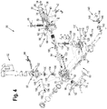
FIG. 1 is an isometric view of a strapping tool in accordance with an example of the present disclosure; -
FIG. 2 is a left-side elevational view of the strapping tool ofFIG. 1 ; -
FIG. 3 illustrates the tool ofFIG. 1 positioned relative to a load being strapped; -
FIG. 4 is an exploded view of the strapping tool ofFIG. 1 ; -
FIG. 5 is an enlarged left-side elevational view similar toFIG. 2 with portions of the strapping tool removed to illustrate an opening assembly in a first position; -
FIG. 6 is an enlarged left-side elevational view similar toFIG. 5 with the opening assembly in a second position; -
FIG. 7 is an enlarged exploded view of a feed wheel drive gear assembly and a weld plate drive gear assembly of the tool ofFIG. 1 ; and -
FIG. 8 is a pneumatic circuit diagram of a strapping tool, such as the tool ofFIG. 1 , in accordance with an example of the present disclosure. - While the present disclosure is susceptible of embodiment in various forms, there is shown in the drawings and will hereinafter be described one or more examples with the understanding that the present disclosure is to be considered illustrative only and is not intended to limit the disclosure to any specific example described or illustrated.
- Referring now to
FIGS. 1-7 , a strapper or strappingtool 20 in accordance with an example of the present disclosure is shown. The illustrated strapper or strapping tool 20 (sometimes referred to herein as "tool" for brevity) is configured to tension a strap or strappingmaterial 22 around an object orload 24, weld overlapping portions of thestrap 22 together, and sever or cut the strap. Generally, thestrap 22 includes a feed orsupply end 26 and afree end 28 that is fed around theload 24 and reinserted into thetool 20 to overlap the feed end. - The
tool 20 includes amotor module assembly 30 operatively coupled to ahead assembly 32. Themotor module assembly 30 includes aconnection 34 for a compressed or pressurized fluid source to drive amotor 36. In one example, themotor 36 is a single reversible air or gas driven motor, the function of which will be described in more detail hereinafter. However, in other examples, themotor 36 can be driven by any other type of hydraulic fluid or may be an electrically driven motor. Themotor module assembly 30 includes amechanism 38 that can be adjusted to change the length of a weld time. In accordance with one example, themechanism 38 can be an adjustable screw that can be turned by hand or with a screwdriver, for example, to adjust the weld time. Further, themotor module assembly 30 includes agrip 40 for a user to hold thetool 20 and actuate anopening switch 42, atensioning switch 44, and awelding switch 46. - The
opening switch 42 is arranged on abottom portion 48 of thegrip 40 such that when a user grasps the grip with an overhand grip, the opening switch is positioned generally proximate the user's index finger and can be actuated similarly to pulling a trigger, as would be understood by one of ordinary skill. Thetensioning switch 44 and thewelding switch 46 are arranged on anupper portion 50 of thegrip 40 such that when the user grasps the grip, the tensioning and welding switches are positioned generally proximate the user's thumb. - The
motor module assembly 30 also includes a weldswitch lockout assembly 60 coupled thereto. The weldswitch lockout assembly 60 is actuated to prevent thewelding switch 46 from being depressed out of order with theopening switch 42 and thetensioning switch 44. In accordance with the present example, the weldswitch lockout assembly 60 includes aweld lockout piston 62 disposed within alockout cylinder 64. Theweld lockout piston 62 is extended and retracted from thelockout cylinder 64 to prevent and allow, respectively, thewelding switch 46 from being depressed, as will be described in more detail hereinafter. Interference orseal members 66, such as o-rings, are disposed on theweld lockout piston 62 and interact with thelockout cylinder 64 to hold the piston in place when the piston is extended and retracted. - The
head assembly 32 of thetool 20 includes agripper housing assembly 70 and atensioning assembly 72 mounted to the gripper housing assembly. Thetensioning assembly 72 includes atensioner foot assembly 74 and afeed wheel 76. Thetensioner foot assembly 74 is pivotally mounted about apivot pin 78 to thegripper housing assembly 70 so that thefoot assembly 74 can pivot toward and away from thefeed wheel 76. Abiasing element 80, such as a torsion spring, is further disposed over thepivot pin 78 and is configured to bias thetensioner foot assembly 74 in a first position against thefeed wheel 76, as shown generally inFIG. 5 . More particularly, thetensioner foot assembly 74 includes agripper plug 82 that is biased against thefeed wheel 76 by thebiasing element 80 in the first position. - The
feed wheel 76 is rotatably mounted to thegripper housing assembly 70 and is operatively coupled to a feed wheeldrive gear assembly 84. The feed wheeldrive gear assembly 84 is further operatively coupled to themotor 36, which is actuated in a first direction, for example, a clockwise direction, to rotate thegear assembly 84 and thefeed wheel 76. In accordance with one example, when overlapping portions ofstrap 22 are clamped between thegripper plug 82 and thefeed wheel 76 and themotor 36 is actuated in the first direction, the feed wheel rotates and tensions the strap by driving thefeed end 26 of the strap in the direction indicated by anarrow 86 inFIG. 3 . - The illustrated
tool 20 also includes amechanism 88 that can be adjusted to change the maximum tension drawn by thefeed wheel 76. In accordance with one example, themechanism 88 can be an adjustable screw that can be turned by hand or with a screwdriver, for example, to adjust the size of a compressed gas flow passage to themotor 36 and, thus, to adjust the revolutions-per-minute of the motor and a stall out tension of thefeed wheel 76. - In accordance with the present example, the
tool 20 also includes an opening assembly ormechanism 90 that performs a powered opening operation when theopening switch 42 is depressed. Theopening assembly 90 is shown more clearly inFIGS. 4-6 and includes afoot lever 92 coupled to thetensioner foot assembly 74, such as at thepivot pin 78. When thetensioner foot assembly 74 is in a first position or stage, as seen inFIG. 5 , thefoot lever 92 has aproximate portion 94 that extends generally horizontally away from the lever and adistal portion 96 that extends generally angularly away from the proximate portion. In the present example, thedistal portion 96 curves upwardly away from theproximate portion 94. Alternatively, thedistal portion 96 may extend linearly, angularly away from theproximate portion 94. - The
opening assembly 90 is actuated by movement of afirst piston 100 disposed within afirst piston chamber 102 coupled to thegear housing assembly 70. In the present example, afirst piston rod 104 with aninclined plane member 106 is coupled to thefirst piston 100, such that actuation of the first piston downwardly in thefirst piston chamber 102 drives the first piston rod downwardly from the first position, as seen inFIG. 5 , to a second position or stage, as seen inFIG. 6 . Anextension spring 108 disposed between thepiston rod 104 and thefirst piston 100 biases the piston rod and piston upwardly to the first position. - In one example of the opening
assembly 90 in use, thefirst piston 100 is driven downwardly, such as by routing compressed gas into thefirst piston chamber 102. The downward movement of thefirst piston 100 engages and drives theinclined plane member 106 of thepiston rod 104 downward. Theinclined plane member 106 contacts thedistal portion 96 of thefoot lever 92 in the first position, as shown inFIG. 5 , and exerts a maximum opening force to push thetensioner foot assembly 74 and thegripper plug 82 away from thefeed wheel 76. Thefirst piston 100 is further driven downward so that theinclined plane member 106 of thepiston rod 104 contacts theproximate portion 94 of thefoot lever 92, as shown inFIG. 6 , to rotate thetensioner foot assembly 74 and thegripper plug 82 away from thefeed wheel 76 and provide maximum clearance for inserting and removing thestrap 22. - The
head assembly 32 further includes aweld plate assembly 110 mounted to thegripper housing assembly 70. Theweld plate assembly 110 includes alower weld gripper 112 and anupper weld gripper 114. In the present example, theweld plate assembly 110 includes afoot 116 and thelower weld gripper 112 is held stationary with respect to theweld plate assembly 110 on the foot. Theupper weld gripper 114 is coupled to alinkage arm 118, such as by apivot pin 120, and the linkage arm is operatively coupled to a weld platedrive gear assembly 122. In the present example, the weld platedrive gear assembly 122 includes aneccentric shaft 124 that is disposed within a generallycircular opening 126 defined in thelinkage arm 118. The weld platedrive gear assembly 122 is further operatively coupled to themotor 36, which is actuated to rotate the weld plate drive gear assembly. Rotation of the weld platedrive gear assembly 122 causes theeccentric shaft 124 to rotate within thecircular opening 126 in thelinkage arm 118, thereby causing an oscillating vibration of theupper weld gripper 114. - In one example, actuation of the
motor 36 in the first direction (e.g., the clockwise direction) or in a second direction (e.g., a counterclockwise direction) causes the weld platedrive gear assembly 122 and theeccentric shaft 124 to rotate, thereby causing theupper weld gripper 114 to vibrate. However, the weld operation is only performed when theupper weld gripper 114 is vibrating and being forced against thelower weld gripper 112. - In accordance with the illustrated example, the
weld plate assembly 110 includes asecond piston 130 disposed within asecond piston chamber 132, wherein the second piston is actuated to force theupper weld gripper 114 against thelower weld gripper 112. More particularly, asecond piston rod 134 is coupled to thesecond piston 132, such that actuation of the second piston drives the second piston rod downwardly against thelinkage arm 118 to force theupper weld gripper 114 against thelower weld gripper 112. The force of theupper weld gripper 114 against thelower weld gripper 112 and the vibration of the upper weld gripper welds overlapping portions ofstrap 22 together. A biasingelement 136, such as a spring, is further disposed within thesecond piston chamber 130 to bias thesecond piston 132 and thepiston rod 134 away from thelinkage arm 118 until the second piston is actuated to perform the weld operation. In one example, the actuation of thesecond piston 132 to force theupper weld gripper 114 against thelower gripper 112 corresponds with the actuation of themotor 36 in the second direction, for example the counterclockwise direction, to perform the weld operation. - In addition, a cutting
assembly 140 is coupled to theweld plate assembly 110 to cut thestrap 22. More particularly, the cuttingassembly 140 includes acontact plate 142 coupled to acutter insert holder 144. Acutter 146 is further coupled to thecutter insert holder 144 and thecontact plate 142 is mounted to thesecond piston 132 to move downwardly onto thefeed end 26 of thestrap 22 along with thelinkage arm 118 and theupper weld gripper 114. The cuttingassembly 140 includes aspring 148 so that thecutter 146 is allowed to float within thecutter insert holder 144 to assure that thetop feed end 26 of thestrap 22 is cut and thefree end 28 of the strap is not cut. - Referring now to
FIG. 7 , the feed wheel and the weld platedrive gear assemblies motor 36, which can be a single reversible motor, to drive both assemblies. In the present example, the feed wheeldrive gear assembly 84 includes adrive belt 160 coupled to themotor 36, such as to a drive shaft (not shown) of the motor, as would be apparent to one of ordinary skill in the art. Thedrive belt 160 is further coupled to afirst wheel 162 of apulley assembly 164. Themotor 36 is actuated to drive thedrive belt 160 and rotate thefirst wheel 162 and asecond wheel 166 of thepulley assembly 164. Aroller clutch 168 is disposed within thepulley assembly 164 and is coupled to a drive shaft orpinion 170, such as a spiroid pinion. When themotor 36 is actuated in the first direction, thedrive belt 160 rotates thepulley assembly 164 in the first direction and theroller clutch 168 engages thepinion 170 to rotate same. When themotor 36 is actuated in the second direction, thedrive belt 160 rotates thepulley assembly 164 in the second direction but theroller clutch 168 disengages from thepinion 170 and freewheels around the pinion. Thepinion 170 is further coupled to rotate thefeed wheel 76 to perform the tensioning operation. - A
brake assembly 180 is further coupled to the feed wheeldrive gear assembly 84 to prevent thefeed wheel 76 from reversing direction and releasing tension from the clampedstrap 22 until theopening switch 42 is depressed. In accordance with the present example, thebrake assembly 180 includes atoothed brake wheel 182 coupled to thepinion 170 by asecond roller clutch 184. Thesecond roller clutch 184 engages thepinion 170 when same is rotated in the second direction and disengages from the pinion when same is rotated in the first direction. Thebrake assembly 180 further includes apawl assembly 186 that is coupled to thegear housing assembly 70. In the present example, thepawl assembly 186 includes apawl 188 disposed on a first end of abrake pin 190 and abrake lever 192 disposed on a second opposing end of the brake pin. Abrake spring 194 and abrake roller 196 are further coupled to thebrake pin 190. Thebrake spring 194 biases thepawl assembly 186 so that thepawl 188 is engaged with thetoothed brake wheel 182 to prevent same from rotating in the second direction and allowing tension to be released from thestrap 22. - When the
opening switch 42 is depressed and theopening assembly 90 actuated, the opening assembly interacts with thepawl assembly 186 to disengage thebrake wheel 182 and allow thepinion 170 to rotate in the second direction. The rotation of thepinion 170 in the second direction allows thefeed wheel 76 to reverse direction and release tension from thestrap 22, which can then be more easily removed from thestrapper 20. In one example, when the openingassembly 90 is actuated, thefirst piston rod 104 is driven downward and engages thebrake lever 192, which in turn rotates thepawl 188 out of engagement with thebrake wheel 182. - The weld plate
drive gear assembly 122 further includes aweld belt 198 that is coupled thesecond wheel 166 of thepulley assembly 162 and to theeccentric shaft 124. Themotor 36 is actuated in the first or second directions to drive thedrive belt 160, which rotates thepulley assembly 164 and drives theweld belt 198. Driving theweld belt 198 rotates theeccentric shaft 124 and causes theupper weld gripper 114 to vibrate. In the present example, theupper weld gripper 114 vibrates when themotor 36 is actuated in the first or second directions. However, the vibration of theupper weld gripper 114 does not weld overlapping portions of thestrap 22 together until thesecond piston 130 is actuated to force theupper weld gripper 114 against thelower weld gripper 112, as described above. - The feed wheel and the weld plate
drive gear assemblies assemblies - Referring now to the pneumatic circuit or
module 200 ofFIG. 8 , gas is supplied to thetool 20 through acompressed gas supply 202 and enters atension pilot valve 204, which is normally biased in an off or closed position. In the illustrated circuit, thetension pilot valve 204 is configured to supply a continuous flow of gas, regardless of whether the tension pilot valve is off or on, to anopening valve 206 and a weld pilot valve 208. Thetension pilot valve 204 may be any suitable valve, such as a 3 or 4 port and 2 position valve, as would be apparent to one of ordinary skill in the art. Theopening valve 206 and the weld pilot valve 208 are both normally biased in off positions, as shown inFIG. 8 . Theopening valve 206 and the weld pilot valve 208 are also shown generally back-to-back inFIG. 4 . Gas from the compressedgas supply 202 is also routed to aback side 210 of aseal valve 212 and aback side 214 of atension valve 216 to bias the seal valve and the tension valve in off or closed positions, as shown. - Depression or actuation of the
opening switch 42 moves theopening valve 206 to an on or open position, which routes gas to thefirst piston chamber 102 to separate and open thetensioner foot assembly 74 and the gripper plug 82 from thefeed wheel 76 so that thestrap 22 can be inserted or removed therefrom, as described above. Once thestrap 22 is inserted or removed, theopening switch 42 can be released and theopening valve 206 returned to the off position so that gas is no longer routed to thefirst piston chamber 102 and the biasingelement 80 is allowed to bias thetensioner foot assembly 74 and thegripper plug 82 back against thefeed wheel 76. - Moving the
opening valve 206 to the on position also routes gas to aback side 218 of the weld pilot valve 208 to force the pilot valve to the off position and to ensure that thewelding switch 46 is not depressed. Simultaneously therewith, gas is routed to the weldswitch lockout assembly 60 to extend theweld lockout piston 62, which engages and prevents depression of thewelding switch 46. - With the
strap 22 gripped between thegripper plug 82 and thefeed wheel 76, a user can depress or actuate thetensioning switch 44 to move thetension pilot valve 204 to an on or open position, which routes gas to afront side 220 of thetension valve 216 to move the tension valve to an on position. When thetension valve 216 is in the on position, gas is routed from thegas supply 202 through the tension valve to themotor 36 to actuate the motor in the first direction. The actuation of themotor 36 in the first direction rotates the feed wheeldrive gear assembly 84 and causes thefeed wheel 76 to rotate and tension thestrap 22. Generally, thestrap 22 is being tensioned around aload 24 and themotor 36 will stall out when a maximum amount of tension is drawn by thefeed wheel 76. However, thetension switch 44 may be held down as long as desired and can be released at any time before the maximum tension is drawn. Further, as discussed above, themechanism 88 can be coupled to themotor 36 to adjust a flow of compressed gas to the motor and, thus, adjust the maximum tension at stall out. - Actuation of the
tension pilot valve 204 to the on position also routes gas to the weldswitch lockout assembly 60 to retract theweld lockout piston 62 and allow theweld switch 46 to be depressed. Consequently, the weld operation cannot be initiated out of order with the tensioning operation. - Depression or actuation of the
weld switch 46 moves the weld pilot valve 208 to an on or open position, which routes gas to thesecond piston chamber 132 to force theupper weld gripper 114 against thelower weld gripper 112. Actuation of the weld pilot valve 208 to the on position also routes gas to a weld shut-offvalve 222. The weld shut-offvalve 222 is normally biased in an on or open position so that gas routed thereto is further routed to a front side 224 of theseal valve 212 to move the seal valve to an on or open position. When theseal valve 212 is in the on position, gas is routed from thegas supply 202 to themotor 36 to actuate the motor in the second direction. The actuation of themotor 36 in the second direction rotates the weld platedrive gear assembly 122 and causes theupper weld gripper 114 to vibrate and weld thestrap 22, as discussed above. - Actuation of the weld pilot valve 208 to the open position also routes gas to a
weld timer valve 226 and aback side 228 of acheck valve 230. In one example, theweld timer valve 226 is a variable orifice valve that regulates a flow rate of gas to a timing chamber oraccumulator 232. The regulated flow of gas through theweld timer valve 226 increases the pressure in thetiming chamber 232 over time, thus providing a timing function. Gas from thetiming chamber 232 is routed to afront side 234 of the weld shut-offvalve 222 as the pressure increases in the timing chamber. When the pressure in thetiming chamber 232 reaches a predetermined pressure, the gas routed to thefront side 234 of the weld shut-offvalve 222 causes the weld shut-off valve to close, thus stopping or isolating the gas flow to theseal valve 212 and stopping rotation of themotor 36 in the second direction and vibration of theupper weld gripper 114. Themechanism 38, discussed above, can be coupled to theweld timer valve 226 to adjust the flow rate and, thus, adjust the weld time. - In the present example, once the
weld switch 46 is depressed and the weld pilot valve 208 moved to the open position, the weld pilot valve remains biased in the open position. The weld pilot valve 208 does not return to the off or closed position until theopening switch 42 is again depressed or actuated. When theopening switch 42 is again depressed, theopening valve 206 is moved to the open position and gas is rotated to theback side 218 of the weld pilot valve 208 to move the weld pilot valve to the closed position. With the weld pilot valve 208 in the closed position, gas is no longer routed to theback side 228 of thecheck valve 230 and gas is allowed to vent from thetiming chamber 232 through the check valve. Thereafter, the opening, tensioning, and welding operations can be repeated, as described above.
Claims (15)
- A hand-operated strapping tool (20) comprising:a compressed gas driven motor (36);a tensioning assembly (72) coupled to the motor;an opening assembly (90) coupled to the tensioning assembly and actuated by movement of a first piston (100) disposed within a first piston chamber (102) to unclamp the strap during a powered opening operation; anda weld plate assembly (110) coupled to the motor, the weld plate assembly including an upper weld gripper (114), a lower weld gripper (112) and a second piston (130) disposed within a second piston chamber (132); wherein:the motor actuates the tensioning assembly to tension overlapping strap portions clamped by the tensioning assembly during a tensioning operation;the second piston is actuated to force the upper weld gripper against the lower weld gripper during a welding operation; andthe opening assembly is actuated to unclamp the overlapping strap portions during a powered opening operation.
- The strapping tool of claim 1, wherein the tensioning assembly includes a gripper plug (82) movably mounted with respect to a feed wheel (76); wherein:the gripper plug and the feed wheel are configured to clamp the overlapping strap portions therebetween; andthe opening assembly is actuated to move the gripper plug away from the feed wheel during the powered opening operation.
- The strapping tool of claim 2, further comprising a tensioner foot assembly (74) that is pivotally mounted with respect to the feed wheel and a foot lever (92) coupled to the tensioner foot assembly; wherein:the gripper plug is mounted to the tensioner foot assembly; andthe opening assembly engages the foot lever to rotate the tensioner foot assembly and gripper plug away from the foot lever.
- The strapping tool of claim 3, wherein the opening assembly engages the foot lever in a two stage process to push and rotate the gripper plug away from the feed wheel.
- The strapping tool of claim 4, wherein the foot lever includes:a proximate portion (94); anda distal portion (96) that extends generally angularly away from the proximate portion;wherein the opening assembly:engages the distal portion during a first stage of the two stage process; andengages the proximate portion during a second stage of the two stage process.
- The strapping tool of claim 3, wherein:the first piston is actuated by compressed gas to engage the foot lever during the powered opening operation;an opening piston rod (104) with an inclined plane (106) is coupled to the first piston; andthe first piston is actuated within the opening piston chamber so that the inclined plane engages the foot lever during the powered opening operation.
- The strapping tool of claim 1, for tensioning and securing a strap (22), further comprising a pneumatic system coupled to the motor, the weld plate assembly, the tensioning assembly, and the opening assembly; wherein:the motor controls the weld plate assembly to weld the strap to itself during a welding operation;the motor controls the tensioning assembly to tension the strap during a tensioning operation; andthe pneumatic system further includes a compressed gas inlet to the system, a tension pilot valve (204) for controlling a flow of compressed gas to actuate the motor in a first direction during the tensioning operation, a weld pilot valve (208) for controlling a flow of compressed gas to actuate the motor in a second direction and an opening valve (206) for controlling a flow of compressed gas to the opening assembly to actuate the first piston during the powered opening operation.
- The strapping tool of claim 7, wherein:the weld pilot valve is further coupled to a weld timer valve (226) that regulates a flow of compressed gas to a timing chamber (232) configured to isolate gas flow to the motor upon reaching a predetermined pressure in the chamber;the opening valve is further configured to route a flow of compressed gas to the weld pilot valve to de-actuate same and to a weld switch lockout assembly (60) to prevent actuation of the weld pilot valve; andthe tension pilot valve is further configured to route a flow of compressed gas to the weld switch lockout assembly to allow actuation of the weld pilot valve.
- The strapping tool of claim 1, for tensioning and securing a strap (22), further comprising a weld time adjusting mechanism (38); wherein:the motor is actuated in a first direction to control the tensioning assembly to tension the strap during a tensioning operation;the motor is actuated in a second direction to control the weld plate assembly to weld the strap to itself during a predetermined weld time during a welding operation; andthe weld time adjusting mechanism is configured to change a length of the predetermined weld time.
- The strapping tool of claim 9, wherein:the tensioning assembly includes a feed wheel (76) coupled to the motor by a drive gear assembly (84), wherein:when the motor is actuated in the first direction, the drive gear assembly rotates the feed wheel to tension the strap; andwhen the motor is actuated in the second direction, the motor does not rotate the feed wheel; andthe drive gear assembly includes a pinion (170) coupled to the feed wheel to rotate same, wherein the motor is coupled to the pinion by a roller clutch (168) that engages the pinion when the motor is actuated in the first direction and disengages from the pinion when the motor is actuated in the second direction.
- The strapping tool of claim 10, further comprising a brake assembly (180) coupled to the drive gear assembly for preventing the pinion from rotating in the second direction when the brake assembly is engaged.
- The strapping tool of claim 11, wherein the brake assembly includes a toothed wheel (182) that is coupled to the pinion by a second roller clutch (184) that engages the pinion when the pinion is rotated in the second direction and disengages from the pinion when the pinion is rotated in the first direction.
- The strapping tool of claim 9, wherein:the upper weld gripper is coupled to the motor by a drive gear assembly;during the welding operation, the motor is actuated in the second direction to drive the drive gear assembly to vibrate the upper weld gripper; andduring the tensioning operation the motor is actuated in the first direction to drive the gear assembly and vibrate the upper weld gripper but the second piston is not actuated to force the upper weld gripper against the lower weld gripper.
- The strapping tool of claim 9, wherein:the powered opening operation is performed upon actuation of an opening switch (42);the tensioning operation is performed upon actuation of a tensioning switch (44); andthe welding operation is performed upon actuation of a welding switch (46).
- The strapping tool of claim 14, further comprising a weld switch lockout assembly (60) that:engages the weld switch to prevent actuation thereof when the opening switch is actuated; anddisengages the weld switch to allow actuation thereof when the tensioning switch is actuated.
Applications Claiming Priority (3)
| Application Number | Priority Date | Filing Date | Title |
|---|---|---|---|
| US201161445404P | 2011-02-22 | 2011-02-22 | |
| US13/355,284 US8967217B2 (en) | 2011-02-22 | 2012-01-20 | Hand-held strapper |
| PCT/US2012/026078 WO2012116046A1 (en) | 2011-02-22 | 2012-02-22 | Hand-held strapper |
Publications (2)
| Publication Number | Publication Date |
|---|---|
| EP2678228A1 EP2678228A1 (en) | 2014-01-01 |
| EP2678228B1 true EP2678228B1 (en) | 2016-12-21 |
Family
ID=46651282
Family Applications (1)
| Application Number | Title | Priority Date | Filing Date |
|---|---|---|---|
| EP12707009.2A Active EP2678228B1 (en) | 2011-02-22 | 2012-02-22 | Hand-held strapper |
Country Status (4)
| Country | Link |
|---|---|
| US (1) | US8967217B2 (en) |
| EP (1) | EP2678228B1 (en) |
| ES (1) | ES2618791T3 (en) |
| WO (1) | WO2012116046A1 (en) |
Families Citing this family (29)
| Publication number | Priority date | Publication date | Assignee | Title |
|---|---|---|---|---|
| US10518914B2 (en) | 2008-04-23 | 2019-12-31 | Signode Industrial Group Llc | Strapping device |
| US11999516B2 (en) | 2008-04-23 | 2024-06-04 | Signode Industrial Group Llc | Strapping device |
| US9272799B2 (en) | 2011-10-04 | 2016-03-01 | Signode Industrial Group Llc | Sealing tool for strap |
| CH705743A2 (en) | 2011-11-14 | 2013-05-15 | Illinois Tool Works | Strapper. |
| DE102011122155A1 (en) * | 2011-12-23 | 2013-06-27 | Fromm Holding Ag | Pneumatic strapping device |
| US9468968B2 (en) | 2012-08-30 | 2016-10-18 | Signode Industrial Group Llc | Battery powered tensioning tool for strap |
| US9932135B2 (en) | 2012-09-24 | 2018-04-03 | Signode Industrial Group Llc | Strapping device |
| CH708294A2 (en) * | 2013-05-05 | 2014-12-15 | Orgapack Gmbh | Strapper. |
| PL3105128T3 (en) | 2014-02-10 | 2021-11-22 | Signode International Ip Holdings Llc | Strapping device having a strip feed device |
| US20160068287A1 (en) * | 2014-09-05 | 2016-03-10 | Terry Gannon, Jr. | Strapping Assembly |
| US20160376041A1 (en) * | 2015-06-23 | 2016-12-29 | Signode Industrial Group Llc | Battery powered flat tensioner tool |
| US10577137B2 (en) | 2015-12-09 | 2020-03-03 | Signode Industrial Group Llc | Electrically powered combination hand-held notch-type strapping tool |
| CH712984A2 (en) | 2016-09-18 | 2018-03-29 | Signode Ind Group Llc | Strapping device for strapping packaged goods with a strapping band. |
| US11247791B2 (en) * | 2016-12-21 | 2022-02-15 | Taizhou Yongpai Packk Equipment Co., Ltd. | Handheld electric packing machine |
| CH713645A2 (en) * | 2017-01-30 | 2018-09-28 | Signode Ind Group Llc | Strapping device with an actuating element of the clamping device. |
| USD864688S1 (en) | 2017-03-28 | 2019-10-29 | Signode Industrial Group Llc | Strapping device |
| US11174051B2 (en) | 2019-02-15 | 2021-11-16 | Samuel, Son & Co. (Usa) Inc. | Hand held strapping tool |
| US11352153B2 (en) | 2019-05-07 | 2022-06-07 | Signode Industrial Group Llc | Strapping tool |
| CA192342S (en) * | 2019-07-22 | 2021-12-30 | Ergopack Deutschland Gmbh | Packaging machine |
| CN111674600A (en) * | 2020-07-09 | 2020-09-18 | 东莞市精端包装科技有限公司 | A one-button portable automatic baler |
| KR20230036121A (en) * | 2020-07-13 | 2023-03-14 | 시그노드 인더스트리얼 그룹 엘엘씨 | strapping tool |
| USD969883S1 (en) * | 2020-09-08 | 2022-11-15 | Signode Industrial Group Llc | Strapping tool |
| USD953832S1 (en) * | 2020-10-09 | 2022-06-07 | Signode Industrial Group Llc | Strapping tool |
| WO2022087182A1 (en) * | 2020-10-20 | 2022-04-28 | Golden Bear LLC | Strapping tool |
| USD1002312S1 (en) | 2021-04-29 | 2023-10-24 | Signode Industrial Group Llc | Strapping tool |
| US12420966B2 (en) | 2022-02-18 | 2025-09-23 | Signode Industrial Group Llc | Strapping tool with energy-release feature |
| US12397943B2 (en) | 2022-11-29 | 2025-08-26 | Samuel, Son & Co. (Usa) Inc. | Handheld strapping device |
| USD1081310S1 (en) | 2023-07-25 | 2025-07-01 | Signode Industrial Group Llc | Strapping tool |
| CN116946452A (en) * | 2023-08-07 | 2023-10-27 | 浙江维派包装设备有限公司 | Portable packer |
Citations (1)
| Publication number | Priority date | Publication date | Assignee | Title |
|---|---|---|---|---|
| US6732638B1 (en) * | 2003-01-15 | 2004-05-11 | Illinois Tool Works, Inc. | Time-out indicator for pneumatic strapper |
Family Cites Families (11)
| Publication number | Priority date | Publication date | Assignee | Title |
|---|---|---|---|---|
| DE1906457U (en) | 1963-08-14 | 1964-12-10 | Seal Less Strapping Ltd Of Ger | DEVICE FOR TYING UP PACKAGES. |
| US4313779A (en) | 1979-07-30 | 1982-02-02 | Signode Corporation | All electric friction fusion strapping tool |
| US5459977A (en) | 1993-12-09 | 1995-10-24 | Illinois Tool Works Inc. | Method and apparatus for an improved power strapping machine |
| US5518043A (en) | 1995-01-09 | 1996-05-21 | Illinois Tool Works | Readily assembled and disassembled, modular, pneumatically powered strapping tool |
| CA2176799C (en) | 1995-07-31 | 2000-02-29 | David Crittenden | Compact hand operated pneumatic strapping tool |
| US6533013B1 (en) * | 2000-06-02 | 2003-03-18 | Illinois Tool Works Inc. | Electric strapping tool and method therefor |
| US6907717B2 (en) * | 2002-06-14 | 2005-06-21 | Illinois Tool Works, Inc. | Dual motor strapper |
| US6966255B1 (en) | 2004-08-06 | 2005-11-22 | Illinois Tool Works, Inc. | Lock-out for power assisted strapping tool |
| US7155885B1 (en) | 2005-06-28 | 2007-01-02 | Illinois Tool Works, Inc. | Small profile strapping tool |
| US7562620B1 (en) | 2008-01-30 | 2009-07-21 | Illinois Tool Works, Inc. | Strapping tool |
| PL2271553T3 (en) | 2008-04-23 | 2013-09-30 | Signode Int Ip Holdings Llc | Mobile strapping device |
-
2012
- 2012-01-20 US US13/355,284 patent/US8967217B2/en active Active
- 2012-02-22 ES ES12707009.2T patent/ES2618791T3/en active Active
- 2012-02-22 EP EP12707009.2A patent/EP2678228B1/en active Active
- 2012-02-22 WO PCT/US2012/026078 patent/WO2012116046A1/en not_active Ceased
Patent Citations (1)
| Publication number | Priority date | Publication date | Assignee | Title |
|---|---|---|---|---|
| US6732638B1 (en) * | 2003-01-15 | 2004-05-11 | Illinois Tool Works, Inc. | Time-out indicator for pneumatic strapper |
Also Published As
| Publication number | Publication date |
|---|---|
| US20120210682A1 (en) | 2012-08-23 |
| US8967217B2 (en) | 2015-03-03 |
| ES2618791T3 (en) | 2017-06-22 |
| WO2012116046A1 (en) | 2012-08-30 |
| EP2678228A1 (en) | 2014-01-01 |
Similar Documents
| Publication | Publication Date | Title |
|---|---|---|
| US8967217B2 (en) | Hand-held strapper | |
| EP2178762B1 (en) | Two-piece strapping tool | |
| EP1371560B1 (en) | Dual motor strapper | |
| CA2861513C (en) | Tensioner/cutter tool for hose clamps | |
| JP6725661B2 (en) | Electric combination type handheld notch type banding tool | |
| US10773841B2 (en) | Tensioner/cutter tool for hose clamps and/or bands and attachments for tensioner/cutter | |
| US20160376041A1 (en) | Battery powered flat tensioner tool | |
| EP2252513B1 (en) | Improved strapping tool | |
| KR101779161B1 (en) | Battery powered tensioning tool for strap | |
| US7155885B1 (en) | Small profile strapping tool | |
| EP0756992B1 (en) | Pneumatic strapping tool | |
| CA2543819C (en) | Dual motor strapper |
Legal Events
| Date | Code | Title | Description |
|---|---|---|---|
| PUAI | Public reference made under article 153(3) epc to a published international application that has entered the european phase |
Free format text: ORIGINAL CODE: 0009012 |
|
| 17P | Request for examination filed |
Effective date: 20130920 |
|
| AK | Designated contracting states |
Kind code of ref document: A1 Designated state(s): AL AT BE BG CH CY CZ DE DK EE ES FI FR GB GR HR HU IE IS IT LI LT LU LV MC MK MT NL NO PL PT RO RS SE SI SK SM TR |
|
| RAP1 | Party data changed (applicant data changed or rights of an application transferred) |
Owner name: ILLINOIS TOOL WORKS INC. |
|
| DAX | Request for extension of the european patent (deleted) | ||
| RAP1 | Party data changed (applicant data changed or rights of an application transferred) |
Owner name: PREMARK PACKAGING LLC |
|
| RAP1 | Party data changed (applicant data changed or rights of an application transferred) |
Owner name: SIGNODE INTERNATIONAL IP HOLDINGS LLC |
|
| 17Q | First examination report despatched |
Effective date: 20150128 |
|
| GRAP | Despatch of communication of intention to grant a patent |
Free format text: ORIGINAL CODE: EPIDOSNIGR1 |
|
| RIC1 | Information provided on ipc code assigned before grant |
Ipc: B65B 13/18 20060101ALI20160607BHEP Ipc: B65B 13/02 20060101AFI20160607BHEP Ipc: B65B 13/34 20060101ALI20160607BHEP |
|
| INTG | Intention to grant announced |
Effective date: 20160621 |
|
| GRAJ | Information related to disapproval of communication of intention to grant by the applicant or resumption of examination proceedings by the epo deleted |
Free format text: ORIGINAL CODE: EPIDOSDIGR1 |
|
| GRAR | Information related to intention to grant a patent recorded |
Free format text: ORIGINAL CODE: EPIDOSNIGR71 |
|
| GRAS | Grant fee paid |
Free format text: ORIGINAL CODE: EPIDOSNIGR3 |
|
| GRAA | (expected) grant |
Free format text: ORIGINAL CODE: 0009210 |
|
| INTC | Intention to grant announced (deleted) | ||
| INTG | Intention to grant announced |
Effective date: 20161109 |
|
| AK | Designated contracting states |
Kind code of ref document: B1 Designated state(s): AL AT BE BG CH CY CZ DE DK EE ES FI FR GB GR HR HU IE IS IT LI LT LU LV MC MK MT NL NO PL PT RO RS SE SI SK SM TR |
|
| REG | Reference to a national code |
Ref country code: GB Ref legal event code: FG4D |
|
| REG | Reference to a national code |
Ref country code: CH Ref legal event code: EP |
|
| REG | Reference to a national code |
Ref country code: IE Ref legal event code: FG4D |
|
| REG | Reference to a national code |
Ref country code: AT Ref legal event code: REF Ref document number: 855233 Country of ref document: AT Kind code of ref document: T Effective date: 20170115 |
|
| REG | Reference to a national code |
Ref country code: DE Ref legal event code: R096 Ref document number: 602012026807 Country of ref document: DE |
|
| REG | Reference to a national code |
Ref country code: FR Ref legal event code: PLFP Year of fee payment: 6 |
|
| PG25 | Lapsed in a contracting state [announced via postgrant information from national office to epo] |
Ref country code: LV Free format text: LAPSE BECAUSE OF FAILURE TO SUBMIT A TRANSLATION OF THE DESCRIPTION OR TO PAY THE FEE WITHIN THE PRESCRIBED TIME-LIMIT Effective date: 20161221 |
|
| REG | Reference to a national code |
Ref country code: LT Ref legal event code: MG4D |
|
| REG | Reference to a national code |
Ref country code: NL Ref legal event code: MP Effective date: 20161221 |
|
| PG25 | Lapsed in a contracting state [announced via postgrant information from national office to epo] |
Ref country code: NO Free format text: LAPSE BECAUSE OF FAILURE TO SUBMIT A TRANSLATION OF THE DESCRIPTION OR TO PAY THE FEE WITHIN THE PRESCRIBED TIME-LIMIT Effective date: 20170321 Ref country code: LT Free format text: LAPSE BECAUSE OF FAILURE TO SUBMIT A TRANSLATION OF THE DESCRIPTION OR TO PAY THE FEE WITHIN THE PRESCRIBED TIME-LIMIT Effective date: 20161221 Ref country code: GR Free format text: LAPSE BECAUSE OF FAILURE TO SUBMIT A TRANSLATION OF THE DESCRIPTION OR TO PAY THE FEE WITHIN THE PRESCRIBED TIME-LIMIT Effective date: 20170322 Ref country code: SE Free format text: LAPSE BECAUSE OF FAILURE TO SUBMIT A TRANSLATION OF THE DESCRIPTION OR TO PAY THE FEE WITHIN THE PRESCRIBED TIME-LIMIT Effective date: 20161221 |
|
| REG | Reference to a national code |
Ref country code: AT Ref legal event code: MK05 Ref document number: 855233 Country of ref document: AT Kind code of ref document: T Effective date: 20161221 |
|
| PG25 | Lapsed in a contracting state [announced via postgrant information from national office to epo] |
Ref country code: FI Free format text: LAPSE BECAUSE OF FAILURE TO SUBMIT A TRANSLATION OF THE DESCRIPTION OR TO PAY THE FEE WITHIN THE PRESCRIBED TIME-LIMIT Effective date: 20161221 Ref country code: HR Free format text: LAPSE BECAUSE OF FAILURE TO SUBMIT A TRANSLATION OF THE DESCRIPTION OR TO PAY THE FEE WITHIN THE PRESCRIBED TIME-LIMIT Effective date: 20161221 Ref country code: RS Free format text: LAPSE BECAUSE OF FAILURE TO SUBMIT A TRANSLATION OF THE DESCRIPTION OR TO PAY THE FEE WITHIN THE PRESCRIBED TIME-LIMIT Effective date: 20161221 Ref country code: BE Free format text: LAPSE BECAUSE OF NON-PAYMENT OF DUE FEES Effective date: 20170228 |
|
| REG | Reference to a national code |
Ref country code: ES Ref legal event code: FG2A Ref document number: 2618791 Country of ref document: ES Kind code of ref document: T3 Effective date: 20170622 |
|
| PG25 | Lapsed in a contracting state [announced via postgrant information from national office to epo] |
Ref country code: NL Free format text: LAPSE BECAUSE OF FAILURE TO SUBMIT A TRANSLATION OF THE DESCRIPTION OR TO PAY THE FEE WITHIN THE PRESCRIBED TIME-LIMIT Effective date: 20161221 |
|
| PG25 | Lapsed in a contracting state [announced via postgrant information from national office to epo] |
Ref country code: RO Free format text: LAPSE BECAUSE OF FAILURE TO SUBMIT A TRANSLATION OF THE DESCRIPTION OR TO PAY THE FEE WITHIN THE PRESCRIBED TIME-LIMIT Effective date: 20161221 Ref country code: CZ Free format text: LAPSE BECAUSE OF FAILURE TO SUBMIT A TRANSLATION OF THE DESCRIPTION OR TO PAY THE FEE WITHIN THE PRESCRIBED TIME-LIMIT Effective date: 20161221 Ref country code: IS Free format text: LAPSE BECAUSE OF FAILURE TO SUBMIT A TRANSLATION OF THE DESCRIPTION OR TO PAY THE FEE WITHIN THE PRESCRIBED TIME-LIMIT Effective date: 20170421 Ref country code: SK Free format text: LAPSE BECAUSE OF FAILURE TO SUBMIT A TRANSLATION OF THE DESCRIPTION OR TO PAY THE FEE WITHIN THE PRESCRIBED TIME-LIMIT Effective date: 20161221 Ref country code: EE Free format text: LAPSE BECAUSE OF FAILURE TO SUBMIT A TRANSLATION OF THE DESCRIPTION OR TO PAY THE FEE WITHIN THE PRESCRIBED TIME-LIMIT Effective date: 20161221 |
|
| PG25 | Lapsed in a contracting state [announced via postgrant information from national office to epo] |
Ref country code: BE Free format text: LAPSE BECAUSE OF FAILURE TO SUBMIT A TRANSLATION OF THE DESCRIPTION OR TO PAY THE FEE WITHIN THE PRESCRIBED TIME-LIMIT Effective date: 20161221 Ref country code: AT Free format text: LAPSE BECAUSE OF FAILURE TO SUBMIT A TRANSLATION OF THE DESCRIPTION OR TO PAY THE FEE WITHIN THE PRESCRIBED TIME-LIMIT Effective date: 20161221 Ref country code: SM Free format text: LAPSE BECAUSE OF FAILURE TO SUBMIT A TRANSLATION OF THE DESCRIPTION OR TO PAY THE FEE WITHIN THE PRESCRIBED TIME-LIMIT Effective date: 20161221 Ref country code: PL Free format text: LAPSE BECAUSE OF FAILURE TO SUBMIT A TRANSLATION OF THE DESCRIPTION OR TO PAY THE FEE WITHIN THE PRESCRIBED TIME-LIMIT Effective date: 20161221 Ref country code: PT Free format text: LAPSE BECAUSE OF FAILURE TO SUBMIT A TRANSLATION OF THE DESCRIPTION OR TO PAY THE FEE WITHIN THE PRESCRIBED TIME-LIMIT Effective date: 20170421 Ref country code: BG Free format text: LAPSE BECAUSE OF FAILURE TO SUBMIT A TRANSLATION OF THE DESCRIPTION OR TO PAY THE FEE WITHIN THE PRESCRIBED TIME-LIMIT Effective date: 20170321 |
|
| REG | Reference to a national code |
Ref country code: DE Ref legal event code: R097 Ref document number: 602012026807 Country of ref document: DE |
|
| PG25 | Lapsed in a contracting state [announced via postgrant information from national office to epo] |
Ref country code: MC Free format text: LAPSE BECAUSE OF FAILURE TO SUBMIT A TRANSLATION OF THE DESCRIPTION OR TO PAY THE FEE WITHIN THE PRESCRIBED TIME-LIMIT Effective date: 20161221 |
|
| REG | Reference to a national code |
Ref country code: CH Ref legal event code: PL |
|
| PLBE | No opposition filed within time limit |
Free format text: ORIGINAL CODE: 0009261 |
|
| STAA | Information on the status of an ep patent application or granted ep patent |
Free format text: STATUS: NO OPPOSITION FILED WITHIN TIME LIMIT |
|
| PG25 | Lapsed in a contracting state [announced via postgrant information from national office to epo] |
Ref country code: LI Free format text: LAPSE BECAUSE OF NON-PAYMENT OF DUE FEES Effective date: 20170228 Ref country code: CH Free format text: LAPSE BECAUSE OF NON-PAYMENT OF DUE FEES Effective date: 20170228 |
|
| 26N | No opposition filed |
Effective date: 20170922 |
|
| REG | Reference to a national code |
Ref country code: IE Ref legal event code: MM4A |
|
| PG25 | Lapsed in a contracting state [announced via postgrant information from national office to epo] |
Ref country code: DK Free format text: LAPSE BECAUSE OF FAILURE TO SUBMIT A TRANSLATION OF THE DESCRIPTION OR TO PAY THE FEE WITHIN THE PRESCRIBED TIME-LIMIT Effective date: 20161221 |
|
| PG25 | Lapsed in a contracting state [announced via postgrant information from national office to epo] |
Ref country code: LU Free format text: LAPSE BECAUSE OF NON-PAYMENT OF DUE FEES Effective date: 20170222 |
|
| REG | Reference to a national code |
Ref country code: FR Ref legal event code: PLFP Year of fee payment: 7 |
|
| PG25 | Lapsed in a contracting state [announced via postgrant information from national office to epo] |
Ref country code: SI Free format text: LAPSE BECAUSE OF FAILURE TO SUBMIT A TRANSLATION OF THE DESCRIPTION OR TO PAY THE FEE WITHIN THE PRESCRIBED TIME-LIMIT Effective date: 20161221 Ref country code: IE Free format text: LAPSE BECAUSE OF NON-PAYMENT OF DUE FEES Effective date: 20170222 |
|
| PG25 | Lapsed in a contracting state [announced via postgrant information from national office to epo] |
Ref country code: MT Free format text: LAPSE BECAUSE OF NON-PAYMENT OF DUE FEES Effective date: 20170222 |
|
| PG25 | Lapsed in a contracting state [announced via postgrant information from national office to epo] |
Ref country code: HU Free format text: LAPSE BECAUSE OF FAILURE TO SUBMIT A TRANSLATION OF THE DESCRIPTION OR TO PAY THE FEE WITHIN THE PRESCRIBED TIME-LIMIT; INVALID AB INITIO Effective date: 20120222 |
|
| PG25 | Lapsed in a contracting state [announced via postgrant information from national office to epo] |
Ref country code: CY Free format text: LAPSE BECAUSE OF NON-PAYMENT OF DUE FEES Effective date: 20161221 |
|
| PG25 | Lapsed in a contracting state [announced via postgrant information from national office to epo] |
Ref country code: MK Free format text: LAPSE BECAUSE OF FAILURE TO SUBMIT A TRANSLATION OF THE DESCRIPTION OR TO PAY THE FEE WITHIN THE PRESCRIBED TIME-LIMIT Effective date: 20161221 |
|
| PG25 | Lapsed in a contracting state [announced via postgrant information from national office to epo] |
Ref country code: TR Free format text: LAPSE BECAUSE OF FAILURE TO SUBMIT A TRANSLATION OF THE DESCRIPTION OR TO PAY THE FEE WITHIN THE PRESCRIBED TIME-LIMIT Effective date: 20161221 |
|
| PG25 | Lapsed in a contracting state [announced via postgrant information from national office to epo] |
Ref country code: AL Free format text: LAPSE BECAUSE OF FAILURE TO SUBMIT A TRANSLATION OF THE DESCRIPTION OR TO PAY THE FEE WITHIN THE PRESCRIBED TIME-LIMIT Effective date: 20161221 |
|
| PGFP | Annual fee paid to national office [announced via postgrant information from national office to epo] |
Ref country code: GB Payment date: 20220225 Year of fee payment: 11 |
|
| PGFP | Annual fee paid to national office [announced via postgrant information from national office to epo] |
Ref country code: IT Payment date: 20220222 Year of fee payment: 11 Ref country code: FR Payment date: 20220223 Year of fee payment: 11 Ref country code: ES Payment date: 20220301 Year of fee payment: 11 |
|
| GBPC | Gb: european patent ceased through non-payment of renewal fee |
Effective date: 20230222 |
|
| PG25 | Lapsed in a contracting state [announced via postgrant information from national office to epo] |
Ref country code: GB Free format text: LAPSE BECAUSE OF NON-PAYMENT OF DUE FEES Effective date: 20230222 |
|
| PG25 | Lapsed in a contracting state [announced via postgrant information from national office to epo] |
Ref country code: IT Free format text: LAPSE BECAUSE OF NON-PAYMENT OF DUE FEES Effective date: 20230222 Ref country code: GB Free format text: LAPSE BECAUSE OF NON-PAYMENT OF DUE FEES Effective date: 20230222 Ref country code: FR Free format text: LAPSE BECAUSE OF NON-PAYMENT OF DUE FEES Effective date: 20230228 |
|
| PG25 | Lapsed in a contracting state [announced via postgrant information from national office to epo] |
Ref country code: ES Free format text: LAPSE BECAUSE OF NON-PAYMENT OF DUE FEES Effective date: 20230223 |
|
| REG | Reference to a national code |
Ref country code: ES Ref legal event code: FD2A Effective date: 20240426 |
|
| PG25 | Lapsed in a contracting state [announced via postgrant information from national office to epo] |
Ref country code: ES Free format text: LAPSE BECAUSE OF NON-PAYMENT OF DUE FEES Effective date: 20230223 |
|
| PGFP | Annual fee paid to national office [announced via postgrant information from national office to epo] |
Ref country code: DE Payment date: 20250122 Year of fee payment: 14 |