EP2678141B1 - A fixing system of a half-die to a traverse of a press - Google Patents
A fixing system of a half-die to a traverse of a press Download PDFInfo
- Publication number
- EP2678141B1 EP2678141B1 EP12705412.0A EP12705412A EP2678141B1 EP 2678141 B1 EP2678141 B1 EP 2678141B1 EP 12705412 A EP12705412 A EP 12705412A EP 2678141 B1 EP2678141 B1 EP 2678141B1
- Authority
- EP
- European Patent Office
- Prior art keywords
- hole
- traverse
- die
- orientation
- appendages
- Prior art date
- Legal status (The legal status is an assumption and is not a legal conclusion. Google has not performed a legal analysis and makes no representation as to the accuracy of the status listed.)
- Active
Links
Images



Classifications
-
- B—PERFORMING OPERATIONS; TRANSPORTING
- B29—WORKING OF PLASTICS; WORKING OF SUBSTANCES IN A PLASTIC STATE IN GENERAL
- B29C—SHAPING OR JOINING OF PLASTICS; SHAPING OF MATERIAL IN A PLASTIC STATE, NOT OTHERWISE PROVIDED FOR; AFTER-TREATMENT OF THE SHAPED PRODUCTS, e.g. REPAIRING
- B29C33/00—Moulds or cores; Details thereof or accessories therefor
- B29C33/30—Mounting, exchanging or centering
- B29C33/307—Mould plates mounted on frames; Mounting the mould plates; Frame constructions therefor
-
- B—PERFORMING OPERATIONS; TRANSPORTING
- B29—WORKING OF PLASTICS; WORKING OF SUBSTANCES IN A PLASTIC STATE IN GENERAL
- B29C—SHAPING OR JOINING OF PLASTICS; SHAPING OF MATERIAL IN A PLASTIC STATE, NOT OTHERWISE PROVIDED FOR; AFTER-TREATMENT OF THE SHAPED PRODUCTS, e.g. REPAIRING
- B29C33/00—Moulds or cores; Details thereof or accessories therefor
- B29C33/30—Mounting, exchanging or centering
- B29C33/305—Mounting of moulds or mould support plates
-
- B—PERFORMING OPERATIONS; TRANSPORTING
- B29—WORKING OF PLASTICS; WORKING OF SUBSTANCES IN A PLASTIC STATE IN GENERAL
- B29C—SHAPING OR JOINING OF PLASTICS; SHAPING OF MATERIAL IN A PLASTIC STATE, NOT OTHERWISE PROVIDED FOR; AFTER-TREATMENT OF THE SHAPED PRODUCTS, e.g. REPAIRING
- B29C45/00—Injection moulding, i.e. forcing the required volume of moulding material through a nozzle into a closed mould; Apparatus therefor
- B29C45/17—Component parts, details or accessories; Auxiliary operations
- B29C45/1742—Mounting of moulds; Mould supports
- B29C45/1743—Mounting of moulds; Mould supports using mounting means projecting from the back side of the mould or from the front side of the mould support
-
- B—PERFORMING OPERATIONS; TRANSPORTING
- B30—PRESSES
- B30B—PRESSES IN GENERAL
- B30B15/00—Details of, or accessories for, presses; Auxiliary measures in connection with pressing
- B30B15/02—Dies; Inserts therefor; Mounting thereof; Moulds
- B30B15/026—Mounting of dies, platens or press rams
Definitions
- the present invention relates in general to presses, in particular to presses for injection of plastic material.
- This type of machine comprises a fixed platen and a mobile traverse which nears and distances from the fixed platen on a horizontal axis.
- the fixed platen bears a fixed half-die which is associated with precision to a nozzle which injects the plastic material in the molten, liquid or pasty state.
- Each of the two members, the platen and the traverse has a plate-shape and bears a series of threaded holes, generally at least two in number, more often six, which serve to fix the half-die to the member by means of a screw.
- the fixing operation of the half-die to the member is very laborious, and comprises positioning the half-die on the member, inserting and fastening the screws of the respective holes, thus performing a pre-tightening, nearing the two half-dies up to achieving a perfect combination, and then performing the final tightening.
- Document US 6 244 780 relates to the fastening of a cutting tool to a respective activating spur, and exhibits no problem of orientation of the tool in relation to the support.
- the fastening devices described in this document comprise two parts destined to be separately associated to the pieces to be assembled.
- a first part comprises a threaded spur screwed into a hole present in one of the two pieces to be assembled.
- the spur has a cylindrical portion that projects from the surface of the piece, which portion is destined to insert in a complementary first hole present in the other part to be assembled.
- the external surface of the cylindrical portion comprises first parallel channels having a triangular section and a constant pitch, and a seating parallel to the axis which separates the cylindrical part into two symmetrical appendages.
- a second part comprises a sort of clamp suitable for being associated to the other piece to be assembled and destined to clamp the projecting part of the first part.
- the second part exhibits a first hole for receiving the appendages and a second hole opening externally of the piece.
- the second hole exhibits an axis which intersects the axis of the first hole and is destined to receive a through-bolt having an end destined to screw into a first nut snugly inserted in the second hole, and to slidably house a second nut similar to the first.
- the two nuts are connected by a single bolt which, when the parts are assembled, is located in the seating.
- the nuts have facing surfaces thereof provided with triangular-section channels complementary with the external channels of the appendages of the cylindrical portion.
- the assembly of the two parts is obtained by screwing the threaded spur into the complementary hole present in one of the two pieces to be assembled, by inserting the appendages projecting from the spur into the complementary hole present in the other part, and tightening the two nuts connected by the bolt up to co-penetrating the channels thereof in the channels of the appendages.
- the above-described fastening devices exhibit the drawback of not being able to guarantee perfect blocking of the spur in the respective hole, and thus maintaining the desired reciprocal orientation between the two assembled pieces, since the two appendages deriving from the spur have to have an orientation which is compatible with the orientation of the axis of the second hole opening externally of the piece.
- the problem increases when at least two fastening devices are to be provided between two parts to be assembled.
- the structures of the prior art are in particular unsuitable for fixing a half-die to the mobile traverse of a press, as the half-die has to be fixed to at least two points to the traverse by means of two fastening devices having different and predetermined orientations.
- the aim of the present invention is to provide a fastening system of the above-described type, which enables rapid and correct mounting and demounting of a half-die to the mobile traverse and the fixed platen of a press, especially a press for injection of plastic material.
- the aim is attained by the fastening system having the characteristics described in the independent claim.
- the system of the invention comprises a device of the above-cited type having means for blocking the two appendages to one of the two parts to be assembled, with a desired orientation which does not depend on the degree of tightening, but is a function only of the orientation of the second part of the fastening device.
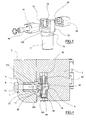
- the figures illustrate a press 1 provided with a fixed platen 2 and a mobile traverse 3 which slides on two guides 31, activated by a hydro-mechanical toggle system 32.
- a known plastic material injection system is associated to the fixed platen 2. The following is equally applicable either to the fixed platen 2 or the traverse 3.
- a half-die 5 is fastened to both the mobile traverse 3 and the fixed platen 2, by means of at least two fastening devices described herein below.
- each fastening device comprises a through-hole 6 having differentiated sections afforded in the traverse.
- a cylindrical spur 7 is snugly inserted in the hole 6 and is provided with a broadened portion 71, which is prolonged beyond the traverse 3.
- the broadened portion 71 is partly contained, with a considerable radial play, in the larger-diameter portion 62 of the hole 6.
- the spur 7 is rested against a first abutment 61 of the differentiated-section hole 6, and retained there by the bolt 8 which is screwed into an axial cavity of the spur.
- the broadened portion 71 of the spur is prolonged into two appendages 73 facing and opposite and separated by an axial space 74.
- the opposing surfaces of the appendages 73 exhibit channels 730 having axes that are perpendicular to the axis of the space 74.
- the half-die 5 to be assembled to the traverse 3 exhibits a hole 9 having differentiated sections destined to be placed coaxial to the hole 6.
- the hole 9 is destined to snugly receive the appendages 73.
- the two appendages 73 are symmetrical with respect to the axis of the spur, and exhibit channels 730 on the external surface which channels 730 are straight and have triangular sections having an axis perpendicular to the axis of the spur 7, and facing externally.
- the body of the half-die 5 is further provided with a hole 90 having an axis perpendicular to the axis and intersecting the axis of the hole 9,and opening externally on the side of the half-die.
- the hole 90 has a quadrangular section, but could have any section.
- Two holes 103 are comprised at the hole 90, which holes 103 are perpendicular to the hole 90 and open onto the surface of the half-die, and are destined each to contain a guide pin, not illustrated, which projects into the hole 90.
- the hole 90 is crossed by the channelled part of the appendages 73, and slidably snugly houses two symmetrical nuts 91 and 92, which on the two flat facing surfaces exhibit channels 93 complementary to the channels 730 present on the appendages 73.
- the nut 91 is simply inserted on a bolt 94, while the opposite nut 92 is screwed to the threaded end of the bolt.
- the stalk of the bolt 94 is positioned in the space 74 between the appendages 73.
- the pin projects from each of the holes 103 internally of a channel 105 afforded on a side of the nut facing the hole 103.
- the orientation of the spur 7 internally of the hole 6 can be defined at the design stage by predisposing two opposite faced-off sections 75 ( figure 5 ) which are situated in complementary seatings afforded in the traverse 3.
- the orientation of the faced-off sections 75 is parallel to the axis of the space 74.
- the first mounting of the half-die on the traverse is performed as follows. Leaving the bolt 8 slightly loose, the spur 7 is orientated such that the oppositely-situated faced-off sections 75 are located in the complementary seatings afforded in the traverse 3, and the space 74 between the appendages 73 can house the stalk of the bolt 94, guaranteeing that the axis of the channels 730 is parallel to the axis of the channels 93.
- the half-die can be associated to the traverse simply by inserting the appendages of the spurs in the facing holes of the half-die, and activating the bolts 94 such as to lock the nuts 91 and 92 against the appendages.
- the two faced-off sections 75, or another equivalent abutment, are not indispensable.
- the first mounting of the half-die is performed, leaving the bolt 8 loose, by inserting the two appendages 75 and performing a first tightening of the bolts 91 and 92.
- the spur self-orientates in the correct position, and can be blocked by tightening the bolt 8.
- the two appendages 73 derive from the base of a plate 700 which is fixed, with a fixed and predetermined orientation, to the traverse 3 of the press by four screws 702 housed in the holes 701 and acting on the bottom of the hole 6.
- the orientation of the plate is in this case defined by a crest 703 present on the plate which inserts in a corresponding cavity of the traverse.
- the two holes 9 and 90 afforded in the half-die 5 which open externally will during the design stage of the half-die have to be orientated such as to be respectively coaxial to the hole 6 and correctly orientated with respect to the orientation of the channels 730 deriving from the plate 700 and the crest 703.
- the realisation modes are easily understandable from what has been stated in relation to the first embodiment.
- the part of the fastening element comprising the spur if the dimensions of the traverse and the half-die permit it, can be advantageously associated to the half-die, while the part comprising the fastening bolts can be realised in the traverse.
Landscapes
- Engineering & Computer Science (AREA)
- Mechanical Engineering (AREA)
- Manufacturing & Machinery (AREA)
- Moulds For Moulding Plastics Or The Like (AREA)
- Connection Of Plates (AREA)
- Paper (AREA)
- Coating With Molten Metal (AREA)
- Casting Or Compression Moulding Of Plastics Or The Like (AREA)
- Mounting, Exchange, And Manufacturing Of Dies (AREA)
Description
- The present invention relates in general to presses, in particular to presses for injection of plastic material.
- This type of machine comprises a fixed platen and a mobile traverse which nears and distances from the fixed platen on a horizontal axis.
- Each of the two members, the platen and the traverse, bears a half-die provided with one or more moulds destined to combine perfectly with the mould of the other half-die.
- The fixed platen bears a fixed half-die which is associated with precision to a nozzle which injects the plastic material in the molten, liquid or pasty state. Each of the two members, the platen and the traverse, has a plate-shape and bears a series of threaded holes, generally at least two in number, more often six, which serve to fix the half-die to the member by means of a screw. The fixing operation of the half-die to the member is very laborious, and comprises positioning the half-die on the member, inserting and fastening the screws of the respective holes, thus performing a pre-tightening, nearing the two half-dies up to achieving a perfect combination, and then performing the final tightening.
- This operation, very costly in terms of time, has to be repeated each time the die is to be changed, which, given the high productivity of this type of machine is done with a certain frequency and implicates long down times which have a negative influence on productivity.
- Thus the problem of realising a fastening system of the half-die to the traverse and platen of the press which involves only short operating times while preserving the necessary precision of fixing is very relevant.
- General rapid fastening means are known in the prior art, described for example in document
US 6 244 780 . - Document
US 6 244 780 relates to the fastening of a cutting tool to a respective activating spur, and exhibits no problem of orientation of the tool in relation to the support. - The fastening devices described in this document comprise two parts destined to be separately associated to the pieces to be assembled.
- A first part comprises a threaded spur screwed into a hole present in one of the two pieces to be assembled.
- The spur has a cylindrical portion that projects from the surface of the piece, which portion is destined to insert in a complementary first hole present in the other part to be assembled.
- The external surface of the cylindrical portion comprises first parallel channels having a triangular section and a constant pitch, and a seating parallel to the axis which separates the cylindrical part into two symmetrical appendages.
- A second part comprises a sort of clamp suitable for being associated to the other piece to be assembled and destined to clamp the projecting part of the first part.
- The second part exhibits a first hole for receiving the appendages and a second hole opening externally of the piece.
- The second hole exhibits an axis which intersects the axis of the first hole and is destined to receive a through-bolt having an end destined to screw into a first nut snugly inserted in the second hole, and to slidably house a second nut similar to the first.
- The two nuts are connected by a single bolt which, when the parts are assembled, is located in the seating.
- The nuts have facing surfaces thereof provided with triangular-section channels complementary with the external channels of the appendages of the cylindrical portion.
- The assembly of the two parts is obtained by screwing the threaded spur into the complementary hole present in one of the two pieces to be assembled, by inserting the appendages projecting from the spur into the complementary hole present in the other part, and tightening the two nuts connected by the bolt up to co-penetrating the channels thereof in the channels of the appendages.
- The orientation of the spur in the hole in which it is screwed is entirely random, as will be the reciprocal orientation of the two pieces.
- The above-described fastening devices exhibit the drawback of not being able to guarantee perfect blocking of the spur in the respective hole, and thus maintaining the desired reciprocal orientation between the two assembled pieces, since the two appendages deriving from the spur have to have an orientation which is compatible with the orientation of the axis of the second hole opening externally of the piece.
- The structures of the prior art are not suitable for application where there is a need for a perfect fastening of the spur, respective a compulsory orientation between the two parts to be assembled.
- The problem increases when at least two fastening devices are to be provided between two parts to be assembled.
- The structures of the prior art are in particular unsuitable for fixing a half-die to the mobile traverse of a press, as the half-die has to be fixed to at least two points to the traverse by means of two fastening devices having different and predetermined orientations.
- Examples of such fastening devices, according to the preamble of the
claim 1, are described inDE 33 31 676 and inUS 5,078,586 . - The aim of the present invention is to provide a fastening system of the above-described type, which enables rapid and correct mounting and demounting of a half-die to the mobile traverse and the fixed platen of a press, especially a press for injection of plastic material.
- The aim is attained by the fastening system having the characteristics described in the independent claim.
- The system of the invention comprises a device of the above-cited type having means for blocking the two appendages to one of the two parts to be assembled, with a desired orientation which does not depend on the degree of tightening, but is a function only of the orientation of the second part of the fastening device.
- The constructional and functional advantages and characteristics will emerge from the detailed description that follows, with the aid of the figures of the accompanying drawings, which illustrated a particular preferred embodiment thereof, given by way of non-limiting example.
-
Figure 1 show a side view of a press for injection of plastic material. -
Figure 2 is the view from II offigure 1 . -
Figure 3 is the front view of the mobile traverse. -
Figure 4 is second IV-IV offigure 2 . -
Figure 5 is a larger-scale detail offigure 4 . -
Figure 6 is a second of a detail of a different embodiment of the invention. -
Figure 7 is a larger-scale detail offigure 6 . - The figures illustrate a
press 1 provided with afixed platen 2 and amobile traverse 3 which slides on twoguides 31, activated by a hydro-mechanical toggle system 32. - A known plastic material injection system is associated to the
fixed platen 2. The following is equally applicable either to the fixedplaten 2 or thetraverse 3. - A half-
die 5 is fastened to both themobile traverse 3 and the fixedplaten 2, by means of at least two fastening devices described herein below. - In a first embodiment (
figures 4 and 5 ) each fastening device comprises a through-hole 6 having differentiated sections afforded in the traverse. - A
cylindrical spur 7 is snugly inserted in thehole 6 and is provided with a broadenedportion 71, which is prolonged beyond thetraverse 3. - The broadened
portion 71 is partly contained, with a considerable radial play, in the larger-diameter portion 62 of thehole 6. - The
spur 7 is rested against afirst abutment 61 of the differentiated-section hole 6, and retained there by thebolt 8 which is screwed into an axial cavity of the spur. - The broadened
portion 71 of the spur is prolonged into twoappendages 73 facing and opposite and separated by anaxial space 74. - The opposing surfaces of the
appendages 73exhibit channels 730 having axes that are perpendicular to the axis of thespace 74. - The half-
die 5 to be assembled to thetraverse 3 exhibits a hole 9 having differentiated sections destined to be placed coaxial to thehole 6. - The hole 9 is destined to snugly receive the
appendages 73. - The two
appendages 73 are symmetrical with respect to the axis of the spur, andexhibit channels 730 on the external surface whichchannels 730 are straight and have triangular sections having an axis perpendicular to the axis of thespur 7, and facing externally. - The body of the half-
die 5 is further provided with ahole 90 having an axis perpendicular to the axis and intersecting the axis of the hole 9,and opening externally on the side of the half-die. Thehole 90 has a quadrangular section, but could have any section. - Two
holes 103 are comprised at thehole 90, whichholes 103 are perpendicular to thehole 90 and open onto the surface of the half-die, and are destined each to contain a guide pin, not illustrated, which projects into thehole 90. - The
hole 90 is crossed by the channelled part of theappendages 73, and slidably snugly houses twosymmetrical nuts channels 93 complementary to thechannels 730 present on theappendages 73. - The
nut 91 is simply inserted on abolt 94, while theopposite nut 92 is screwed to the threaded end of the bolt. - The stalk of the
bolt 94 is positioned in thespace 74 between theappendages 73. - The pin, not illustrated, projects from each of the
holes 103 internally of achannel 105 afforded on a side of the nut facing thehole 103. - The orientation of the
spur 7 internally of thehole 6 can be defined at the design stage by predisposing two opposite faced-off sections 75 (figure 5 ) which are situated in complementary seatings afforded in thetraverse 3. The orientation of the faced-offsections 75 is parallel to the axis of thespace 74. The first mounting of the half-die on the traverse is performed as follows. Leaving thebolt 8 slightly loose, thespur 7 is orientated such that the oppositely-situated faced-offsections 75 are located in the complementary seatings afforded in thetraverse 3, and thespace 74 between theappendages 73 can house the stalk of thebolt 94, guaranteeing that the axis of thechannels 730 is parallel to the axis of thechannels 93. - The position of the
spur 71 is then blocked by thebolt 8, and the operation is repeated for each of the fastening devices provided between the mobile traverse and the half-die. - Then the half-die can be associated to the traverse simply by inserting the appendages of the spurs in the facing holes of the half-die, and activating the
bolts 94 such as to lock the nuts 91 and 92 against the appendages. - The two faced-off
sections 75, or another equivalent abutment, are not indispensable. In this case the first mounting of the half-die is performed, leaving thebolt 8 loose, by inserting the twoappendages 75 and performing a first tightening of thebolts bolt 8. - Then the process continues as reported above.
- Since the design of the traverse of the press on which the half-dies are to be mounted is known, when designing the half-dies the only specification that has to be respected is the coaxial arrangement of the holes 9 of the half-die with the
holes 6 of the traverse, while the third hole has to be orientated parallel to the faced-offsections 75. - In a second embodiment (
figures 6 and 7 ), where the same numerical references are used to indicate the parts corresponding to those of the first embodiment, the twoappendages 73 derive from the base of aplate 700 which is fixed, with a fixed and predetermined orientation, to thetraverse 3 of the press by fourscrews 702 housed in theholes 701 and acting on the bottom of thehole 6. - The orientation of the plate is in this case defined by a
crest 703 present on the plate which inserts in a corresponding cavity of the traverse. - The two
holes 9 and 90 afforded in the half-die 5 which open externally will during the design stage of the half-die have to be orientated such as to be respectively coaxial to thehole 6 and correctly orientated with respect to the orientation of thechannels 730 deriving from theplate 700 and thecrest 703. The realisation modes are easily understandable from what has been stated in relation to the first embodiment. - Clearly the part of the fastening element comprising the spur, if the dimensions of the traverse and the half-die permit it, can be advantageously associated to the half-die, while the part comprising the fastening bolts can be realised in the traverse.
- This enables a considerable cost saving, as any number of half-dies can be associated to a same traverse, and the machining of the part comprising the spur is much easier to do.
Claims (7)
- A system comprising a plane or a plate constituting a mobile traverse (3) or a fixed platen (2) of a press (1), a half-die (5) associated to the traverse (2,3), at least a first hole (6) afforded in the traverse (2,3) or in the half-die (5) and aligned with a second hole (9) afforded respectively in the half-die (5) or in the traverse (2,3), a third hole (90) intersecting the second hole (9) and opening externally on an edge of the half-die (5) or the traverse (2,3), connecting means (7,700) having a part blocked in the first hole (6) by means of fastening means (8,702) and a part (73) inserted in the second hole (9), blocking means (91,92,94) activatable from outside located in the third hole (90) such as to act on the part (73) of the connecting means (7,700) inserted in the second hole (9), characterised in that the fastening means (8,702) between the first hole (6) and the part of the connecting means inserted therein are independently tightenable respect to the orientation of the connecting means (7,700) in the first hole (6).
- The system of claim 1, characterised in that the connecting means (7,700) comprise a portion inserted in the first hole and provided with a part that projects from the surface of the traverse, the projecting part being provided with a space (74) parallel to the axis of the first hole (6), which separates the projecting part into two symmetrical appendages (73), the opposite surfaces of which comprise first channels (730) that are parallel and have a triangular section and a constant pitch, having an axis which is perpendicular to the axis of the space.
- The system of claim 2, characterised in that the portion inserted in the first hole is a cylindrical spur (7) blocked in the first hole by means of a head bolt (8) and comprises means suitable for guaranteeing a desired orientation in the first hole.
- The system of claim 3, characterised in that the means suitable for guaranteeing the desired reciprocal orientation are two faced-off portions (75) afforded on the surface of the spur, which portions are destined to snugly insert in complementary faced-off portions fashioned in the first hole (6).
- The system of claim 2, characterised in that the portion inserted in the first hole is a cylindrical plate (700) blocked in the first hole with a desired orientation and connected to the traverse by means of screws (702) acting between the plate and the bottom of the first hole.
- The system of claim 5, characterised in that the means for guaranteeing the desired reciprocal orientation are a crest (703) fashioned on the base of the plate (700), destined to insert snugly in a complementary channel afforded in the base of the first hole.
- The system of claim 2, characterised in that the blocking means that are activatable from outside located in the third hole comprise two nuts (91,92) inserted unrotatably in the third hole, joined by a bolt (94) passing between the symmetrical appendages and singly provided on the facing surfaces with second channels (93), complementary to the first channels (730) and present on the two appendages.
Applications Claiming Priority (2)
| Application Number | Priority Date | Filing Date | Title |
|---|---|---|---|
| ITRE2011A000011A IT1404496B1 (en) | 2011-02-24 | 2011-02-24 | FIXING SYSTEM OF A SEMISTAMPO TO THE CROSS OF THE PRESS. |
| PCT/IB2012/000241 WO2012114173A1 (en) | 2011-02-24 | 2012-02-08 | A fixing system of a half-die to a traverse of a press |
Publications (2)
| Publication Number | Publication Date |
|---|---|
| EP2678141A1 EP2678141A1 (en) | 2014-01-01 |
| EP2678141B1 true EP2678141B1 (en) | 2015-04-08 |
Family
ID=43976342
Family Applications (1)
| Application Number | Title | Priority Date | Filing Date |
|---|---|---|---|
| EP12705412.0A Active EP2678141B1 (en) | 2011-02-24 | 2012-02-08 | A fixing system of a half-die to a traverse of a press |
Country Status (7)
| Country | Link |
|---|---|
| US (1) | US8747096B2 (en) |
| EP (1) | EP2678141B1 (en) |
| CN (1) | CN102971123B (en) |
| CA (1) | CA2800396C (en) |
| ES (1) | ES2537409T3 (en) |
| IT (1) | IT1404496B1 (en) |
| WO (1) | WO2012114173A1 (en) |
Families Citing this family (1)
| Publication number | Priority date | Publication date | Assignee | Title |
|---|---|---|---|---|
| JP6616385B2 (en) * | 2017-12-01 | 2019-12-04 | ファナック株式会社 | Injection molding machine base |
Family Cites Families (6)
| Publication number | Priority date | Publication date | Assignee | Title |
|---|---|---|---|---|
| CH612862A5 (en) * | 1976-06-29 | 1979-08-31 | Netstal Ag Maschf Giesserei | |
| DE3331676C2 (en) * | 1983-09-02 | 1986-10-23 | Klöckner-Werke AG, 4100 Duisburg | Mold clamping device |
| DE3929717A1 (en) * | 1989-09-07 | 1991-03-14 | Battenfeld Gmbh | FASTENING DEVICE FOR TOOLS ON A TOOL HOLDER |
| FR2706809B1 (en) * | 1993-06-23 | 1995-09-08 | Billion Sa | |
| SE512318C2 (en) | 1997-08-29 | 2000-02-28 | Sandvik Ab | Utilities Connection |
| JP3914937B2 (en) * | 2004-04-05 | 2007-05-16 | ファナック株式会社 | Molding mechanism of injection molding machine |
-
2011
- 2011-02-24 IT ITRE2011A000011A patent/IT1404496B1/en active
-
2012
- 2012-02-08 CN CN201280001678.0A patent/CN102971123B/en active Active
- 2012-02-08 WO PCT/IB2012/000241 patent/WO2012114173A1/en not_active Ceased
- 2012-02-08 CA CA2800396A patent/CA2800396C/en active Active
- 2012-02-08 US US13/817,303 patent/US8747096B2/en active Active
- 2012-02-08 EP EP12705412.0A patent/EP2678141B1/en active Active
- 2012-02-08 ES ES12705412.0T patent/ES2537409T3/en active Active
Also Published As
| Publication number | Publication date |
|---|---|
| ITRE20110011A1 (en) | 2012-08-25 |
| IT1404496B1 (en) | 2013-11-22 |
| ES2537409T3 (en) | 2015-06-08 |
| WO2012114173A1 (en) | 2012-08-30 |
| CN102971123B (en) | 2016-08-03 |
| US20130142900A1 (en) | 2013-06-06 |
| EP2678141A1 (en) | 2014-01-01 |
| CA2800396A1 (en) | 2012-08-30 |
| WO2012114173A8 (en) | 2012-11-01 |
| US8747096B2 (en) | 2014-06-10 |
| CN102971123A (en) | 2013-03-13 |
| CA2800396C (en) | 2018-12-11 |
Similar Documents
| Publication | Publication Date | Title |
|---|---|---|
| US9065172B2 (en) | Mounting hub for antenna | |
| KR101996076B1 (en) | Apparatus and method for manufacturing SUS cap nut by cold forging | |
| DE102016122090B4 (en) | clamping system | |
| CA2800396C (en) | A fixing system of a half-die to a traverse of a press | |
| CN201645181U (en) | Clamp system for rapidly manufacturing mould | |
| US20020155191A1 (en) | Modular mold assembly | |
| CN219967145U (en) | Processing tool for water jacket of automobile cylinder body die casting die | |
| CN102785104A (en) | Small part clamping device | |
| CN204035735U (en) | A kind of clamping jig for Linear cut tilted footstock | |
| CN117463836A (en) | A kind of bending knife mold | |
| CN217514047U (en) | Automatic useless tool in top of cross cutting | |
| CN213858947U (en) | Thin-wall part clamping tool | |
| CN210475227U (en) | Composite die for cutting pouring gate and punching hole of thin-wall part | |
| CA3241370A1 (en) | Configurable base plate system for industrial pumps | |
| CN202762850U (en) | U-shaped piece general die | |
| CN218964748U (en) | Adjustable precision vice modular loading and unloading clamp | |
| CN223431117U (en) | Automobile part laser cutting fixing tool | |
| CN114242519B (en) | Contactor convenient to produce, clamp and assembly process thereof | |
| CN221515836U (en) | Stamping die convenient to dismouting | |
| CN216151771U (en) | Clamp for machine tool | |
| CN220407649U (en) | Welding jig | |
| CN213436708U (en) | Connecting structure for stamping die of electrical cabinet shell | |
| CN217665714U (en) | Punching equipment | |
| CN223630254U (en) | Multi-station tool clamp with adjustable | |
| CN222242268U (en) | Stamping part die for automobile shock absorber parts |
Legal Events
| Date | Code | Title | Description |
|---|---|---|---|
| PUAI | Public reference made under article 153(3) epc to a published international application that has entered the european phase |
Free format text: ORIGINAL CODE: 0009012 |
|
| 17P | Request for examination filed |
Effective date: 20121113 |
|
| AK | Designated contracting states |
Kind code of ref document: A1 Designated state(s): AL AT BE BG CH CY CZ DE DK EE ES FI FR GB GR HR HU IE IS IT LI LT LU LV MC MK MT NL NO PL PT RO RS SE SI SK SM TR |
|
| DAX | Request for extension of the european patent (deleted) | ||
| GRAP | Despatch of communication of intention to grant a patent |
Free format text: ORIGINAL CODE: EPIDOSNIGR1 |
|
| INTG | Intention to grant announced |
Effective date: 20141008 |
|
| GRAS | Grant fee paid |
Free format text: ORIGINAL CODE: EPIDOSNIGR3 |
|
| GRAA | (expected) grant |
Free format text: ORIGINAL CODE: 0009210 |
|
| RIN1 | Information on inventor provided before grant (corrected) |
Inventor name: MOSCA, ROSSANO Inventor name: FINI, MARCO |
|
| AK | Designated contracting states |
Kind code of ref document: B1 Designated state(s): AL AT BE BG CH CY CZ DE DK EE ES FI FR GB GR HR HU IE IS IT LI LT LU LV MC MK MT NL NO PL PT RO RS SE SI SK SM TR |
|
| REG | Reference to a national code |
Ref country code: GB Ref legal event code: FG4D |
|
| REG | Reference to a national code |
Ref country code: CH Ref legal event code: EP |
|
| REG | Reference to a national code |
Ref country code: IE Ref legal event code: FG4D |
|
| REG | Reference to a national code |
Ref country code: AT Ref legal event code: REF Ref document number: 720184 Country of ref document: AT Kind code of ref document: T Effective date: 20150515 |
|
| REG | Reference to a national code |
Ref country code: DE Ref legal event code: R096 Ref document number: 602012006497 Country of ref document: DE Effective date: 20150521 |
|
| REG | Reference to a national code |
Ref country code: ES Ref legal event code: FG2A Ref document number: 2537409 Country of ref document: ES Kind code of ref document: T3 Effective date: 20150608 |
|
| REG | Reference to a national code |
Ref country code: NL Ref legal event code: VDEP Effective date: 20150408 |
|
| REG | Reference to a national code |
Ref country code: LT Ref legal event code: MG4D |
|
| PG25 | Lapsed in a contracting state [announced via postgrant information from national office to epo] |
Ref country code: NL Free format text: LAPSE BECAUSE OF FAILURE TO SUBMIT A TRANSLATION OF THE DESCRIPTION OR TO PAY THE FEE WITHIN THE PRESCRIBED TIME-LIMIT Effective date: 20150408 |
|
| PG25 | Lapsed in a contracting state [announced via postgrant information from national office to epo] |
Ref country code: FI Free format text: LAPSE BECAUSE OF FAILURE TO SUBMIT A TRANSLATION OF THE DESCRIPTION OR TO PAY THE FEE WITHIN THE PRESCRIBED TIME-LIMIT Effective date: 20150408 Ref country code: NO Free format text: LAPSE BECAUSE OF FAILURE TO SUBMIT A TRANSLATION OF THE DESCRIPTION OR TO PAY THE FEE WITHIN THE PRESCRIBED TIME-LIMIT Effective date: 20150708 Ref country code: PT Free format text: LAPSE BECAUSE OF FAILURE TO SUBMIT A TRANSLATION OF THE DESCRIPTION OR TO PAY THE FEE WITHIN THE PRESCRIBED TIME-LIMIT Effective date: 20150810 Ref country code: HR Free format text: LAPSE BECAUSE OF FAILURE TO SUBMIT A TRANSLATION OF THE DESCRIPTION OR TO PAY THE FEE WITHIN THE PRESCRIBED TIME-LIMIT Effective date: 20150408 Ref country code: LT Free format text: LAPSE BECAUSE OF FAILURE TO SUBMIT A TRANSLATION OF THE DESCRIPTION OR TO PAY THE FEE WITHIN THE PRESCRIBED TIME-LIMIT Effective date: 20150408 |
|
| PG25 | Lapsed in a contracting state [announced via postgrant information from national office to epo] |
Ref country code: IS Free format text: LAPSE BECAUSE OF FAILURE TO SUBMIT A TRANSLATION OF THE DESCRIPTION OR TO PAY THE FEE WITHIN THE PRESCRIBED TIME-LIMIT Effective date: 20150808 Ref country code: LV Free format text: LAPSE BECAUSE OF FAILURE TO SUBMIT A TRANSLATION OF THE DESCRIPTION OR TO PAY THE FEE WITHIN THE PRESCRIBED TIME-LIMIT Effective date: 20150408 Ref country code: GR Free format text: LAPSE BECAUSE OF FAILURE TO SUBMIT A TRANSLATION OF THE DESCRIPTION OR TO PAY THE FEE WITHIN THE PRESCRIBED TIME-LIMIT Effective date: 20150709 Ref country code: RS Free format text: LAPSE BECAUSE OF FAILURE TO SUBMIT A TRANSLATION OF THE DESCRIPTION OR TO PAY THE FEE WITHIN THE PRESCRIBED TIME-LIMIT Effective date: 20150408 |
|
| REG | Reference to a national code |
Ref country code: DE Ref legal event code: R097 Ref document number: 602012006497 Country of ref document: DE |
|
| REG | Reference to a national code |
Ref country code: FR Ref legal event code: PLFP Year of fee payment: 5 |
|
| PG25 | Lapsed in a contracting state [announced via postgrant information from national office to epo] |
Ref country code: EE Free format text: LAPSE BECAUSE OF FAILURE TO SUBMIT A TRANSLATION OF THE DESCRIPTION OR TO PAY THE FEE WITHIN THE PRESCRIBED TIME-LIMIT Effective date: 20150408 Ref country code: DK Free format text: LAPSE BECAUSE OF FAILURE TO SUBMIT A TRANSLATION OF THE DESCRIPTION OR TO PAY THE FEE WITHIN THE PRESCRIBED TIME-LIMIT Effective date: 20150408 |
|
| PLBE | No opposition filed within time limit |
Free format text: ORIGINAL CODE: 0009261 |
|
| STAA | Information on the status of an ep patent application or granted ep patent |
Free format text: STATUS: NO OPPOSITION FILED WITHIN TIME LIMIT |
|
| PG25 | Lapsed in a contracting state [announced via postgrant information from national office to epo] |
Ref country code: SK Free format text: LAPSE BECAUSE OF FAILURE TO SUBMIT A TRANSLATION OF THE DESCRIPTION OR TO PAY THE FEE WITHIN THE PRESCRIBED TIME-LIMIT Effective date: 20150408 Ref country code: RO Free format text: LAPSE BECAUSE OF NON-PAYMENT OF DUE FEES Effective date: 20150408 Ref country code: PL Free format text: LAPSE BECAUSE OF FAILURE TO SUBMIT A TRANSLATION OF THE DESCRIPTION OR TO PAY THE FEE WITHIN THE PRESCRIBED TIME-LIMIT Effective date: 20150408 Ref country code: CZ Free format text: LAPSE BECAUSE OF FAILURE TO SUBMIT A TRANSLATION OF THE DESCRIPTION OR TO PAY THE FEE WITHIN THE PRESCRIBED TIME-LIMIT Effective date: 20150408 |
|
| 26N | No opposition filed |
Effective date: 20160111 |
|
| PG25 | Lapsed in a contracting state [announced via postgrant information from national office to epo] |
Ref country code: BE Free format text: LAPSE BECAUSE OF NON-PAYMENT OF DUE FEES Effective date: 20160229 Ref country code: SI Free format text: LAPSE BECAUSE OF FAILURE TO SUBMIT A TRANSLATION OF THE DESCRIPTION OR TO PAY THE FEE WITHIN THE PRESCRIBED TIME-LIMIT Effective date: 20150408 |
|
| PG25 | Lapsed in a contracting state [announced via postgrant information from national office to epo] |
Ref country code: BE Free format text: LAPSE BECAUSE OF FAILURE TO SUBMIT A TRANSLATION OF THE DESCRIPTION OR TO PAY THE FEE WITHIN THE PRESCRIBED TIME-LIMIT Effective date: 20150408 |
|
| PG25 | Lapsed in a contracting state [announced via postgrant information from national office to epo] |
Ref country code: LU Free format text: LAPSE BECAUSE OF FAILURE TO SUBMIT A TRANSLATION OF THE DESCRIPTION OR TO PAY THE FEE WITHIN THE PRESCRIBED TIME-LIMIT Effective date: 20160208 Ref country code: MC Free format text: LAPSE BECAUSE OF FAILURE TO SUBMIT A TRANSLATION OF THE DESCRIPTION OR TO PAY THE FEE WITHIN THE PRESCRIBED TIME-LIMIT Effective date: 20150408 |
|
| REG | Reference to a national code |
Ref country code: CH Ref legal event code: PL |
|
| GBPC | Gb: european patent ceased through non-payment of renewal fee |
Effective date: 20160208 |
|
| PG25 | Lapsed in a contracting state [announced via postgrant information from national office to epo] |
Ref country code: LI Free format text: LAPSE BECAUSE OF NON-PAYMENT OF DUE FEES Effective date: 20160229 Ref country code: CH Free format text: LAPSE BECAUSE OF NON-PAYMENT OF DUE FEES Effective date: 20160229 |
|
| REG | Reference to a national code |
Ref country code: IE Ref legal event code: MM4A |
|
| REG | Reference to a national code |
Ref country code: FR Ref legal event code: PLFP Year of fee payment: 6 |
|
| PG25 | Lapsed in a contracting state [announced via postgrant information from national office to epo] |
Ref country code: GB Free format text: LAPSE BECAUSE OF NON-PAYMENT OF DUE FEES Effective date: 20160208 Ref country code: IE Free format text: LAPSE BECAUSE OF NON-PAYMENT OF DUE FEES Effective date: 20160208 |
|
| REG | Reference to a national code |
Ref country code: AT Ref legal event code: UEP Ref document number: 720184 Country of ref document: AT Kind code of ref document: T Effective date: 20150408 |
|
| PG25 | Lapsed in a contracting state [announced via postgrant information from national office to epo] |
Ref country code: SE Free format text: LAPSE BECAUSE OF FAILURE TO SUBMIT A TRANSLATION OF THE DESCRIPTION OR TO PAY THE FEE WITHIN THE PRESCRIBED TIME-LIMIT Effective date: 20150408 |
|
| PG25 | Lapsed in a contracting state [announced via postgrant information from national office to epo] |
Ref country code: MT Free format text: LAPSE BECAUSE OF FAILURE TO SUBMIT A TRANSLATION OF THE DESCRIPTION OR TO PAY THE FEE WITHIN THE PRESCRIBED TIME-LIMIT Effective date: 20150408 |
|
| REG | Reference to a national code |
Ref country code: FR Ref legal event code: PLFP Year of fee payment: 7 |
|
| PG25 | Lapsed in a contracting state [announced via postgrant information from national office to epo] |
Ref country code: HU Free format text: LAPSE BECAUSE OF FAILURE TO SUBMIT A TRANSLATION OF THE DESCRIPTION OR TO PAY THE FEE WITHIN THE PRESCRIBED TIME-LIMIT; INVALID AB INITIO Effective date: 20120208 Ref country code: SM Free format text: LAPSE BECAUSE OF FAILURE TO SUBMIT A TRANSLATION OF THE DESCRIPTION OR TO PAY THE FEE WITHIN THE PRESCRIBED TIME-LIMIT Effective date: 20150408 Ref country code: CY Free format text: LAPSE BECAUSE OF FAILURE TO SUBMIT A TRANSLATION OF THE DESCRIPTION OR TO PAY THE FEE WITHIN THE PRESCRIBED TIME-LIMIT Effective date: 20150408 |
|
| PG25 | Lapsed in a contracting state [announced via postgrant information from national office to epo] |
Ref country code: TR Free format text: LAPSE BECAUSE OF FAILURE TO SUBMIT A TRANSLATION OF THE DESCRIPTION OR TO PAY THE FEE WITHIN THE PRESCRIBED TIME-LIMIT Effective date: 20150408 Ref country code: MK Free format text: LAPSE BECAUSE OF FAILURE TO SUBMIT A TRANSLATION OF THE DESCRIPTION OR TO PAY THE FEE WITHIN THE PRESCRIBED TIME-LIMIT Effective date: 20150408 Ref country code: MT Free format text: LAPSE BECAUSE OF FAILURE TO SUBMIT A TRANSLATION OF THE DESCRIPTION OR TO PAY THE FEE WITHIN THE PRESCRIBED TIME-LIMIT Effective date: 20160229 |
|
| PG25 | Lapsed in a contracting state [announced via postgrant information from national office to epo] |
Ref country code: BG Free format text: LAPSE BECAUSE OF FAILURE TO SUBMIT A TRANSLATION OF THE DESCRIPTION OR TO PAY THE FEE WITHIN THE PRESCRIBED TIME-LIMIT Effective date: 20150408 |
|
| PG25 | Lapsed in a contracting state [announced via postgrant information from national office to epo] |
Ref country code: AL Free format text: LAPSE BECAUSE OF FAILURE TO SUBMIT A TRANSLATION OF THE DESCRIPTION OR TO PAY THE FEE WITHIN THE PRESCRIBED TIME-LIMIT Effective date: 20150408 |
|
| P01 | Opt-out of the competence of the unified patent court (upc) registered |
Effective date: 20230427 |
|
| PGFP | Annual fee paid to national office [announced via postgrant information from national office to epo] |
Ref country code: ES Payment date: 20260302 Year of fee payment: 15 |
|
| PGFP | Annual fee paid to national office [announced via postgrant information from national office to epo] |
Ref country code: DE Payment date: 20260121 Year of fee payment: 15 |
|
| PGFP | Annual fee paid to national office [announced via postgrant information from national office to epo] |
Ref country code: AT Payment date: 20260123 Year of fee payment: 15 |
|
| PGFP | Annual fee paid to national office [announced via postgrant information from national office to epo] |
Ref country code: IT Payment date: 20260121 Year of fee payment: 15 |
|
| PGFP | Annual fee paid to national office [announced via postgrant information from national office to epo] |
Ref country code: FR Payment date: 20260121 Year of fee payment: 15 |