EP2677934B1 - Methods for monitoring exposure to an event - Google Patents
Methods for monitoring exposure to an event Download PDFInfo
- Publication number
- EP2677934B1 EP2677934B1 EP12749688.3A EP12749688A EP2677934B1 EP 2677934 B1 EP2677934 B1 EP 2677934B1 EP 12749688 A EP12749688 A EP 12749688A EP 2677934 B1 EP2677934 B1 EP 2677934B1
- Authority
- EP
- European Patent Office
- Prior art keywords
- readings
- blast
- stored
- criteria
- pressure
- Prior art date
- Legal status (The legal status is an assumption and is not a legal conclusion. Google has not performed a legal analysis and makes no representation as to the accuracy of the status listed.)
- Active
Links
Images

Classifications
-
- A—HUMAN NECESSITIES
- A61—MEDICAL OR VETERINARY SCIENCE; HYGIENE
- A61B—DIAGNOSIS; SURGERY; IDENTIFICATION
- A61B5/00—Measuring for diagnostic purposes; Identification of persons
- A61B5/103—Measuring devices for testing the shape, pattern, colour, size or movement of the body or parts thereof, for diagnostic purposes
- A61B5/11—Measuring movement of the entire body or parts thereof, e.g. head or hand tremor or mobility of a limb
-
- A—HUMAN NECESSITIES
- A61—MEDICAL OR VETERINARY SCIENCE; HYGIENE
- A61B—DIAGNOSIS; SURGERY; IDENTIFICATION
- A61B5/00—Measuring for diagnostic purposes; Identification of persons
- A61B5/40—Detecting, measuring or recording for evaluating the nervous system
- A61B5/4058—Detecting, measuring or recording for evaluating the nervous system for evaluating the central nervous system
- A61B5/4064—Evaluating the brain
-
- A—HUMAN NECESSITIES
- A61—MEDICAL OR VETERINARY SCIENCE; HYGIENE
- A61B—DIAGNOSIS; SURGERY; IDENTIFICATION
- A61B5/00—Measuring for diagnostic purposes; Identification of persons
- A61B5/72—Signal processing specially adapted for physiological signals or for diagnostic purposes
- A61B5/7271—Specific aspects of physiological measurement analysis
- A61B5/7275—Determining trends in physiological measurement data; Predicting development of a medical condition based on physiological measurements, e.g. determining a risk factor
-
- A—HUMAN NECESSITIES
- A61—MEDICAL OR VETERINARY SCIENCE; HYGIENE
- A61B—DIAGNOSIS; SURGERY; IDENTIFICATION
- A61B5/00—Measuring for diagnostic purposes; Identification of persons
- A61B5/72—Signal processing specially adapted for physiological signals or for diagnostic purposes
- A61B5/7271—Specific aspects of physiological measurement analysis
- A61B5/7282—Event detection, e.g. detecting unique waveforms indicative of a medical condition
-
- G—PHYSICS
- G16—INFORMATION AND COMMUNICATION TECHNOLOGY [ICT] SPECIALLY ADAPTED FOR SPECIFIC APPLICATION FIELDS
- G16H—HEALTHCARE INFORMATICS, i.e. INFORMATION AND COMMUNICATION TECHNOLOGY [ICT] SPECIALLY ADAPTED FOR THE HANDLING OR PROCESSING OF MEDICAL OR HEALTHCARE DATA
- G16H20/00—ICT specially adapted for therapies or health-improving plans, e.g. for handling prescriptions, for steering therapy or for monitoring patient compliance
- G16H20/40—ICT specially adapted for therapies or health-improving plans, e.g. for handling prescriptions, for steering therapy or for monitoring patient compliance relating to mechanical, radiation or invasive therapies, e.g. surgery, laser therapy, dialysis or acupuncture
-
- G—PHYSICS
- G16—INFORMATION AND COMMUNICATION TECHNOLOGY [ICT] SPECIALLY ADAPTED FOR SPECIFIC APPLICATION FIELDS
- G16H—HEALTHCARE INFORMATICS, i.e. INFORMATION AND COMMUNICATION TECHNOLOGY [ICT] SPECIALLY ADAPTED FOR THE HANDLING OR PROCESSING OF MEDICAL OR HEALTHCARE DATA
- G16H40/00—ICT specially adapted for the management or administration of healthcare resources or facilities; ICT specially adapted for the management or operation of medical equipment or devices
- G16H40/60—ICT specially adapted for the management or administration of healthcare resources or facilities; ICT specially adapted for the management or operation of medical equipment or devices for the operation of medical equipment or devices
- G16H40/63—ICT specially adapted for the management or administration of healthcare resources or facilities; ICT specially adapted for the management or operation of medical equipment or devices for the operation of medical equipment or devices for local operation
-
- G—PHYSICS
- G16—INFORMATION AND COMMUNICATION TECHNOLOGY [ICT] SPECIALLY ADAPTED FOR SPECIFIC APPLICATION FIELDS
- G16H—HEALTHCARE INFORMATICS, i.e. INFORMATION AND COMMUNICATION TECHNOLOGY [ICT] SPECIALLY ADAPTED FOR THE HANDLING OR PROCESSING OF MEDICAL OR HEALTHCARE DATA
- G16H50/00—ICT specially adapted for medical diagnosis, medical simulation or medical data mining; ICT specially adapted for detecting, monitoring or modelling epidemics or pandemics
- G16H50/30—ICT specially adapted for medical diagnosis, medical simulation or medical data mining; ICT specially adapted for detecting, monitoring or modelling epidemics or pandemics for calculating health indices; for individual health risk assessment
-
- A—HUMAN NECESSITIES
- A61—MEDICAL OR VETERINARY SCIENCE; HYGIENE
- A61B—DIAGNOSIS; SURGERY; IDENTIFICATION
- A61B2560/00—Constructional details of operational features of apparatus; Accessories for medical measuring apparatus
- A61B2560/02—Operational features
- A61B2560/0204—Operational features of power management
- A61B2560/0209—Operational features of power management adapted for power saving
-
- A—HUMAN NECESSITIES
- A61—MEDICAL OR VETERINARY SCIENCE; HYGIENE
- A61B—DIAGNOSIS; SURGERY; IDENTIFICATION
- A61B2560/00—Constructional details of operational features of apparatus; Accessories for medical measuring apparatus
- A61B2560/02—Operational features
- A61B2560/0242—Operational features adapted to measure environmental factors, e.g. temperature, pollution
Definitions
- Traumatic brain injury (TBI) from an explosive blast remains a significant problem for military personnel, especially those involved in counter insurgency operations. Mild to moderate TBI may be difficult to detect immediately post event, with cognitive or motor deficits manifesting weeks or months post event.
- blows and other types of events are a significant problem for other individuals as well.
- recreational and professional athletes in many sport activities are routinely exposed to blows and other types of events with unknown individual or cumulative effects.
- bike and motorcycle riders may experience some type of blow or other event by way of example only.
- CA 2743472 an apparatus is provided for recording information about an event resulting in application of a force to a body.
- the apparatus comprises data recording means for recording the information, sensor means for sensing a parameter which enables a predetermined source of force to be distinguished from another, different source of force, and control means responsive to the sensed parameter for controlling the data recording means.
- the sensor means may comprise a pressure sensor for sensing shockwaves resulting from an explosive force and the resulting signal used to distinguish from other events, such as blunt impacts.
- the pressure signal may be used to control the storage of acceleration data for injury analysis.
- a non-transitory computer readable medium having stored thereon instructions for monitoring exposure to an event comprising machine executable code which when executed by at least one processor, causes the processor to perform including obtaining sensor readings from at least one sensor.
- An event is identified based on at least one of one or more of the obtained sensor readings or one or more determinations based on the obtained sensor readings meeting one or more selection. At least one of the one or more determinations or the sensor readings which meet one or more of the selection criteria when the event is identified is stored.
- a dosimetry apparatus includes a processor coupled to a memory, the processor configured to execute programmed instructions stored in the memory including obtaining sensor readings from at least one sensor. An event is identified based on at least one of one or more of the obtained sensor readings or one or more determinations based on the obtained sensor readings meeting one or more selection. At least one of the one or more determinations or the sensor readings which meet one or more of the selection criteria when the event is identified is stored.
- This technology provides a number of advantages including providing a more effective and efficient event monitoring dosimetry apparatus.
- event data from a blast or blow can be captured and utilized to guide triage and treatment of exposed individuals. Additionally, this technology can capture and provide event data that will help to provide a better understanding the mechanisms of traumatic brain injury resulting from an explosive blast or blow.
- This technology can be used in a variety of different applications, such as for the military, sporting activities, and other daily activities by way of example only.
- this technology could be helmet mounted, helmet strap mounted, worn on the torso, mounted within vehicle cabins, on vehicle exteriors and/or on building by way of example only.
- this technology could be mounted within helmets, on helmet straps, on headbands, on caps, and/or on uniforms by way of example only.
- this could be mounted to helmets used for bicycles and motorcycles by way of example.
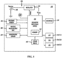
- FIG. 1 An exemplary event monitoring dosimetry apparatus 10 is illustrated in FIG. 1 .
- This example of an event monitoring dosimetry apparatus 10 a dosimetry processing device 12 with a memory 14, an interface device 16, a pressure sensor 18, an inertial monitoring unit 22, an atmospheric sensor 28, a strain gauge 29, a power system 30, an engagement device 32, and a series of different colored LEDs with different numeric indicators 34(1)-34(3), although the apparatus 10 could include other types and numbers of systems, devices, components and elements in other configurations.
- This technology provides a number of advantages including provide a more effective and efficient event monitoring dosimetry apparatus.
- the dosimetry processing device 12 comprises one or more processors coupled to the memory 14 by a bus or other links, although other numbers and types of systems, devices, components, and elements in other configurations and locations can be used.
- the one or more processors in the dosimetry processing device 12 executes a program of stored instructions for one or more aspects of the present technology as described and illustrated by way of the examples herein, although other types and numbers of processing devices and logic could be used and the processor could execute other numbers and types of programmed instructions..
- the memory 14 in the dosimetry processing device 12 stores these programmed instructions, data and other information for one or more aspects of the present technology as described and illustrated herein, although some or all of the programmed instructions could be stored and executed elsewhere.
- the flow chart shown in FIG. 2 is representative of example steps or actions of this technology that may be embodied or expressed as one or more non-transitory computer or machine readable instructions stored in memory 14 that may be executed by the one or more processors.
- the interface device 16 in the dosimetry processing device 12 is used to operatively couple and communicate between the dosimetry processing device 12 and one or more external computing or storage devices, although other types and numbers of communication networks or systems with other types and numbers of connections and configurations can be used.
- the interface device 16 may be used to: (1) activate the dosimetry processing device 12 and load on time and date stamp; (2) adjust criteria and other parameters, (3) reprogram the dosimetry processing device 12, (4) extract data, such as stored readings, identified events, and/or any analysis, although the interface device can be utilized for other types and numbers of functions
- dosimetry processing device 12 can be implemented on any suitable computer system or computing device. It is to be understood that the devices and systems of the examples described herein are for exemplary purposes, as many variations of the specific hardware and software used to implement the examples are possible, as will be appreciated by those skilled in the relevant art(s).
- system of the examples may be conveniently implemented using one or more general purpose computer systems, microprocessors, digital signal processors, and micro-controllers, programmed according to the teachings of the examples, as described and illustrated herein, and as will be appreciated by those ordinary skill in the art.
- the examples may also be embodied as a non-transitory computer readable medium having instructions stored thereon for one or more aspects of the present technology as described and illustrated by way of the examples herein, as described herein, which when executed by a processor, cause the processor to carry out the steps necessary to implement the methods of the examples, as described and illustrated herein.
- the pressure sensor 18 is coupled to the dosimetry processing device 12, although the pressures sensor 18 could be coupled to other types and numbers of devices.
- the pressure sensor 18 is a single pressure sensor, although other types and numbers of pressure sensors could be used..
- the inertial monitoring unit 22 is a low-g (for example 16g) three -axis accelerometer to capture linear acceleration in three axes, although other types (for example a high-g 100 to 2000g) and numbers of inertial measurement units could be used.
- the inertial measurement unit 22 could be a gyroscope which records rotational acceleration.
- the three-axis acceleration information from the inertial monitoring unit 22 can be used by the dosimetry processing device 12 to determine the vector of movement coincident with the arrival of the pressure shock front.
- the dosimetry processing device 12 could use time of flight differences to determine a direction of the blast or other event based on the pressure readings.
- the atmospheric sensor 28 is coupled to the dosimetry processing device 12 and provides temperature, humidity, or light readings, although other types and numbers of environmental monitors could be used, the atmospheric sensor 28 could be positioned to take other readings, and the atmospheric sensor could be part of the dosimetry processing device 12.
- the dosimetry apparatus 10 also may include an optional strain gauge 29 coupled to provide stress measurement readings relating to a blast or other event to the dosimetry processing device 12, although other types and numbers of other sensors could be used.
- the power system 30 includes a battery 36 coupled to a regulator 38 which is coupled to the dosimetry processing device 12, although other types of power systems with other types and numbers of components, such as one with an energy harvester and/or without a regulator 38 could be used.
- the regulator 38 is coupled to regulate power provided by the battery 36 to the dosimetry processing device 12. Additionally, in this example power for the pressure sensor 18, the inertial measurement unit 22, the atmospheric sensor 28, and/or the strain gauge 29 is coupled directly from the dosimetry processing device 12 to save power, although other types and numbers of devices and systems could be coupled directly to the dosimetry processing device 12 to provide power.
- the engagement device 32 such as a button by way of example only, is coupled to the dosimetry processing device 12, although the engagement device could be coupled in other manners.
- the engagement device 32 can be used to request an output of readings including of identified events, stored events and/or assessments of the readings.
- other types and numbers of mechanisms for engaging the dosimetry processing device 12 can be used, such as another computing device coupling to the dosimetry processing device 12 through the interface 16 to request and obtain output data and other information, download a time and date stamp, set and/or reprogram criteria and other parameters by way of example only.
- the series of different colored LEDs with different numeric indicators 34(1)-34(3) are used to provide a status indication for the output stored readings and of the assessment of the stored readings associated with identified events to provide immediate triage of the severity of an event or to present an injury risk assessment, although other types and numbers of displays with other types of symbols which provide other types of outputs can be used.
- LED 34(1) is green colored and has a numeric indicator of zero
- LED 34(2) is yellow colored and has a numeric indicator of one
- LED 34(1) is red colored and has a numeric indicator of two, although other colors and alphanumeric indicators or other symbols could be used.
- step 100 at least one dosimetry apparatus 10 is secured to a location on an object, although other types and manners for securing the one or more dosimetry apparatuses 10 to the object can be used.
- the interface 16 of dosimetry processing device 12 can be used for a number of different types of functions, such as activating the dosimetry processing apparatus 10, loading a current time and date stamp into the dosimetry processing device 12, adding or modifying criteria and other parameter, and/or programming the dosimetry processing device 12 by way of example only.
- the engagement device 32 may also be used for activating the dosimetery processing apparatus 10. In this example, this step is illustrated at the start of this method, but this step can be performed at any time during this exemplary method.
- the dosimetry processing device 12 in the dosimetry apparatus 10 obtains readings from the at least one of the pressure sensor 18, the inertial measurement unit 22, atmospheric sensor 28, and/or the strain gauge 29, although the dosimetry apparatus 10 can obtain readings from other types and numbers of sensors.
- the pressure sensor 18 is a single pressure sensor which obtains pressure readings.
- the inertial measurement unit 22 is a three-axis accelerometer which obtains linear acceleration readings in real time, although other types of inertial measurement units can be used, such as a gyroscope which obtains rotational acceleration readings.
- the atmospheric sensor 28 can obtain one or more temperature, humidity, or ambient light readings in the dosimetry apparatus 10 which can be reviewed by the dosimetry processing device 12 and used to adjust one or more of the sensors, such as the pressure sensor 18, inertial measurement unit 22, atmospheric sensor 28, and/or strain gauge 29 by way of example only.
- the strain gauge 29 may obtain stress measurement readings resulting from a blast or other event and provide them to the dosimetry processing device 12.
- the dosimetry processing device 12 also may obtain and record one or more voltage measurements of the systems, devices and/or components in the dosimetry apparatus 10 which can be utilized to identify false positive events and for other diagnostics.
- the dosimetry processing device 12 optionally may for example determine a direction of the event based on the acceleration readings from three-axis accelerometer 22 and the pressure readings from the single pressure sensor 18 or in another example from pressure readings from multiple linked dosimetry apparatuses 10, although other manners for determining a direction of the event can be used.
- the dosimetry processing device 12 also may adjust threshold for injury risk assessment in memory 14 based on the determined direction of the event. For example to adjust the thresholds when body shielding has blocked some of the event or for impact directions where the body is more prone to injury.
- the dosimetry processing device 12 may switch from a lower power mode to a higher power mode based on identifying of one of the sensor readings which meet one or more of the selection criteria , although other manners for switching power modes can be used and there may be more than two different power modes.
- the dosimetry processing device 12 also may adjust the rate of obtaining the sensor readings in step 102 from a first sample rate in the lower power mode and a second sample rate which is higher than the first sample rate in the higher power mode, although other types of adjustments in sampling could be used.
- the dosimetry processing device 12 may identify an event when at least one of the obtained pressure readings is above a stored pressure reading threshold in memory 14 and/or at least one of the acceleration readings is above a stored acceleration reading threshold in memory 14, although an event could be identified based on other readings and calculations and in other manners, for example by analyzing one or more pressure readings and one or more acceleration readings during an event time window.
- the dosimetry processing device 12 might utilize an infinite impulse response (IIR) filter that allows both feed forward and feedback weighting coefficients to be implemented.
- IIR infinite impulse response
- the filtered signal is used as a baseline against which real time measurements are compared.
- a capture event is identified.
- Alternate filtering techniques could also be leveraged for either approach.
- the dosimetry processing device 12 also may identify an event when at least one of: one of the pressure readings is above the stored pressure threshold a set number of the pressure readings are above the stored pressure threshold; a first set number of pressure readings in a set is above a minimum stored threshold and below a maximum stored threshold for the set; a calculated pressure impulse from the pressure readings is above a stored pressure impulse threshold; at least one high pass filtered one of the pressure readings is above the stored pressure threshold as described above; at least one low pass filtered one of the pressure readings is above the stored pressure threshold; the pressure readings have a positive phase above a stored positive pressure threshold, followed by a negative phase below a stored positive pressure threshold by way of example only.
- the dosimetry processing device 12 also may identify an event when at least one of: at least one of the acceleration readings has an acceleration value in an x, y, or z direction that is above a stored acceleration value threshold; a first set number of acceleration readings in the x, y, or z direction in a set is above a minimum stored threshold and below a maximum stored threshold for the set; at least one of the acceleration readings has an acceleration vector magnitude above a stored acceleration vector magnitude threshold; and at least one of the acceleration readings has a vector or axis acceleration impulse above a stored acceleration impulse threshold.
- the dosimetry processing device 12 also may identify an event when at least one of: at least one of the acceleration readings has a rotational acceleration reading above a stored rotational acceleration threshold; at least one of the a first set number of rotational acceleration readings in a set is above a minimum stored threshold and below a maximum stored threshold for the set; rotational acceleration readings have an acceleration magnitude above a stored acceleration magnitude threshold; and/or at least one of the rotational acceleration readings has an acceleration impulse above a stored acceleration impulse threshold by way of example only.
- the dosimetry processing device 12 also may identify an event when one of the sensor readings is above a stored sensor threshold and a set number of subsequent sensor readings are which meet one or more of the selection criteria or when during an event time window one of the pressure readings is above a stored pressure criteria and one of the acceleration readings which corresponds with the one of the pressure readings is above a stored acceleration criteria.
- the dosimetry processing device 12 optionally may determine when the identified event is a false positive and then may store data related to the false positive event, such as peak recorded values although other types and amounts of data could be stored. By way of example only, the dosimetry processing device 12 may determined whether other related sensor readings within a set period of time also identify the event or may evaluate whether the obtained sensor readings that identified an event represent an anomaly signifying an false positive. If in step 110, the dosimetry processing device 12 determines the identified event is not a false positive, then the No branch is taken to step 112.
- step 110 the dosimetry processing device 12 determines the identified event is a false positive, then the Yes branch is taken to step 111.
- step 111 the dosimetry processing device 12 may store all of the data related to the false positive event in memory 14 or some other subset of the data and then proceeds to step 116.
- the dosimetry processing device 12 may conduct real time event analysis of the obtained pressure and/or acceleration readings and determine a injury risk assessment based on the conducted analysis, although other types and numbers of assessments based on other types and numbers of readings, such as from the atmospheric sensor 28 and/or the strain gauge 29 by way of example only, can be performed.
- the obtained readings may be compared by the dosimetry processing device 12 against stored tables of threshold readings in memory 14 to identify when one or more of the obtained readings are above the corresponding stored threshold reading in the table to identify an event.
- the dosimetry processing device 12 assesses the severity of the event based on an amount the one or more of the obtained readings are above the corresponding stored threshold reading in the table, although other manners for conducting event analysis and determining a injury risk assessment can be used.
- the dosimetry processing device 12 stores the determined risk assessment in memory 14, although the determined risk assessments can be stored in other locations and manners.
- the dosimetry processing device 12 stores the obtained pressure readings from the pressure sensor 18, acceleration readings from the inertial measurement unit 22, atmospheric readings from the atmospheric sensor 28, stress measurement readings from the strain gauge 29, and/or the determined direction in memory 14 , although other types and amounts of readings and other data could be stored, such as the identified one or more events, the determined injury risk assessment, and any interaction with or processing activity of the dosimetry processing device 12, such as through the engagement device 32 or the interface 16 as described earlier in step 101 by way of example, and in other locations and manners. Additionally, the dosimetry processing device 12 may store a record of any switch between a low power mode and a higher power mode with a time and date stamp when the switch occurred.
- the dosimetry processing device 12 may store any type of activity or change of state in the dosimetry apparatus 10, such as every time there was an acceleration reading above a stored threshold or all acceleration readings below a stored threshold for a certain period of time by way of example only. Further, the dosimetry processing device 12 may store a plurality of the identified events and other data as described herein up to a set limit, such as a capacity limit of memory 14, and then could replace one of the stored plurality of events with a next identified event when the set limit is reached based on one or more stored rules or storage retention criteria, such as identified events with lower severity assessments which may result in keeping the current stored plurality of events without adding the newly captured event and the dosimetry processing device 12 could retain all or a portion of the information, such as peak record values and/or a time and date stamp by way of example only, related to the rejected event in memory 14 or in other storage locations based on configuration of instructions on the dosimetry processing device 12.
- a set limit such as a capacity limit of memory 14
- the dosimetry processing device 12 determines whether an output is requested, such as by activation of the engagement device 32 or a request via the interface 16, such as a USB, from another computing device, although other manners for output requests could be used.
- the activating of the engagement device could trigger a display on one of the LEDs 34(1)-34(3), although other types of outputs could be triggered, such as an output of data and other information.
- the engagement device 32 also can have other functions, such as providing outputting different information based on a number of times the button is pressed or the length of time the button is pressed or powering on or off the dosimetry apparatus 10.
- the request for data through the interface 16 from another computing device can be for all or requested portions of the stored data. If in step 116, the dosimetry processing device 12 determines an output has not been requested, then the No branch is taken back to step 102 as described earlier.
- step 116 the dosimetry processing device 12 determines an output has been requested, then the Yes branch is taken to step 117.
- the dosimetry processing device 12 may store information relating to the output request, such as a type of request, what data was requested, and a time and date of the request by way of example, although other types and amounts of data and information relating to the output request can be stored.
- the dosimetry processing device 12 provides the requested output, such as a display on one of the LEDs 34(1)-34(3) or an output of one or more of the stored readings, the identified event, a determined injury risk assessment based on the conducted analysis, data relating to switches between power modes, data relating to output requests, and/or identified false positive events and related data by way of example only via the interface 16, although the information could be output to other devices, other types and amounts of information and other data could be provided and the information and data can be obtained in other manners, such as through a connection with another computing device interacting with the dosimetry processing device 12 via the interface 16 .
- the requested output such as a display on one of the LEDs 34(1)-34(3) or an output of one or more of the stored readings, the identified event, a determined injury risk assessment based on the conducted analysis, data relating to switches between power modes, data relating to output requests, and/or identified false positive events and related data by way of example only via the interface 16, although the information could be output to other devices, other types
- the dosimetry processing device 12 can output the identified event with determined injury risk assessment based on the conducted analysis by illumination of one of the LEDs 34(1) with a numeric indicator in response to the activation by the engagement device 32, although other types and amounts of information could be provided. For example, if the determined injury risk assessment for the identified event is moderate, e.g. within a first range of one or more of the first thresholds then the yellow colored LED 34(2) with the numeric indicator of one is illuminated / flashed. If the determined injury risk assessment for the identified event is severe, e.g. above a first range of one or more of the first thresholds then the red colored LED 34(3) with the numeric indicator of two is illuminated / flashed.
- the green colored LED 34(1) with the numeric indicator of zero is illuminated. Additionally, a requested output could trigger the dosimetry processing device 12 to output the stored readings, determined direction and other data described in the examples herein with or without the assessment information via the interface device 16 to another computing device. Next, this method can return back to step 102 until the exemplary dosimetry apparatus 10 is turned off or the power runs out.
- this technology provides a more effective and efficient event monitoring dosimetry apparatus.
- event data from a blast or blow can be captured and utilized to provide real time analysis for triage, and detailed analysis to guide treatment of exposed individuals.
- this technology can capture and provide event data that will help to provide a better understanding the mechanisms of traumatic brain injury resulting from an explosive blast or blow.
- this technology can be manufactured at a low cost to be disposable.
- a data storage method stored as programmed instructions executed by the dosimetry processing device in this example captures high data rate pressure and acceleration data for a first period of time and low data rate acceleration data for a second period of time, although other time periods could be used. This approach allows response to the event to be captured, with resulting, slower bulk object movement captured while minimizing data storage requirements.
Landscapes
- Health & Medical Sciences (AREA)
- Life Sciences & Earth Sciences (AREA)
- Engineering & Computer Science (AREA)
- Public Health (AREA)
- Medical Informatics (AREA)
- General Health & Medical Sciences (AREA)
- Biomedical Technology (AREA)
- Surgery (AREA)
- Pathology (AREA)
- Biophysics (AREA)
- Animal Behavior & Ethology (AREA)
- Physics & Mathematics (AREA)
- Heart & Thoracic Surgery (AREA)
- Veterinary Medicine (AREA)
- Molecular Biology (AREA)
- Physiology (AREA)
- Neurology (AREA)
- Epidemiology (AREA)
- Primary Health Care (AREA)
- Signal Processing (AREA)
- Psychiatry (AREA)
- Artificial Intelligence (AREA)
- Computer Vision & Pattern Recognition (AREA)
- Neurosurgery (AREA)
- Psychology (AREA)
- Oral & Maxillofacial Surgery (AREA)
- Dentistry (AREA)
- Nuclear Medicine, Radiotherapy & Molecular Imaging (AREA)
- Business, Economics & Management (AREA)
- General Business, Economics & Management (AREA)
- Urology & Nephrology (AREA)
- Databases & Information Systems (AREA)
- Data Mining & Analysis (AREA)
- Measurement Of The Respiration, Hearing Ability, Form, And Blood Characteristics Of Living Organisms (AREA)
- Measuring Fluid Pressure (AREA)
- User Interface Of Digital Computer (AREA)
- Recording Measured Values (AREA)
Description
- Traumatic brain injury (TBI) from an explosive blast remains a significant problem for military personnel, especially those involved in counter insurgency operations. Mild to moderate TBI may be difficult to detect immediately post event, with cognitive or motor deficits manifesting weeks or months post event.
- Additionally, exposure to other types of blows and other types of events is a significant problem for other individuals as well. For example, recreational and professional athletes in many sport activities are routinely exposed to blows and other types of events with unknown individual or cumulative effects. Additionally, bike and motorcycle riders may experience some type of blow or other event by way of example only.
- Currently, there is no widely deployed system to dose the exposure to an explosive blast, blow or other type of event. Given the nature of TBI, the wide variability in explosions, blows and other events and as well as the physical configurations during a blast events, and the variability in human response to each blast event, a widely deployed system to all personnel in a theater is needed to build a database of sufficient size to allow real-time dosimeter data to be used for triage and to monitor and assess military and non-military personnel depending on the particular application. In
CA 2743472 , an apparatus is provided for recording information about an event resulting in application of a force to a body. The apparatus comprises data recording means for recording the information, sensor means for sensing a parameter which enables a predetermined source of force to be distinguished from another, different source of force, and control means responsive to the sensed parameter for controlling the data recording means. The sensor means may comprise a pressure sensor for sensing shockwaves resulting from an explosive force and the resulting signal used to distinguish from other events, such as blunt impacts. The pressure signal may be used to control the storage of acceleration data for injury analysis. Other relevant prior art is described inUS 2009/0000377 A1 ,US 2005/0177929 A1 ,US 2010/0005571 A1 ,US 6892621 B2 . - According to the present invention there is provided a method for monitoring exposure to a blast event as defined in the appended claim 1. Further beneficial features are recited in the associated dependent claims.
- A non-transitory computer readable medium having stored thereon instructions for monitoring exposure to an event comprising machine executable code which when executed by at least one processor, causes the processor to perform including obtaining sensor readings from at least one sensor. An event is identified based on at least one of one or more of the obtained sensor readings or one or more determinations based on the obtained sensor readings meeting one or more selection. At least one of the one or more determinations or the sensor readings which meet one or more of the selection criteria when the event is identified is stored.
- A dosimetry apparatus includes a processor coupled to a memory, the processor configured to execute programmed instructions stored in the memory including obtaining sensor readings from at least one sensor. An event is identified based on at least one of one or more of the obtained sensor readings or one or more determinations based on the obtained sensor readings meeting one or more selection. At least one of the one or more determinations or the sensor readings which meet one or more of the selection criteria when the event is identified is stored.
- This technology provides a number of advantages including providing a more effective and efficient event monitoring dosimetry apparatus. With this technology, event data from a blast or blow can be captured and utilized to guide triage and treatment of exposed individuals. Additionally, this technology can capture and provide event data that will help to provide a better understanding the mechanisms of traumatic brain injury resulting from an explosive blast or blow.
- This technology can be used in a variety of different applications, such as for the military, sporting activities, and other daily activities by way of example only. For military applications, this technology could be helmet mounted, helmet strap mounted, worn on the torso, mounted within vehicle cabins, on vehicle exteriors and/or on building by way of example only. For sporting activities, this technology could be mounted within helmets, on helmet straps, on headbands, on caps, and/or on uniforms by way of example only. For daily activities, this could be mounted to helmets used for bicycles and motorcycles by way of example.
-
-
FIG. 1 is a diagram of an exemplary event monitoring dosimetry apparatus; and -
FIG. 2 is an exemplary method for monitoring events with the exemplary event monitoring dosimetry apparatus. - An exemplary event
monitoring dosimetry apparatus 10 is illustrated inFIG. 1 . This example of an event monitoring dosimetry apparatus 10 adosimetry processing device 12 with amemory 14, aninterface device 16, apressure sensor 18, aninertial monitoring unit 22, anatmospheric sensor 28, astrain gauge 29, apower system 30, anengagement device 32, and a series of different colored LEDs with different numeric indicators 34(1)-34(3), although theapparatus 10 could include other types and numbers of systems, devices, components and elements in other configurations. This technology provides a number of advantages including provide a more effective and efficient event monitoring dosimetry apparatus. - Referring more specifically to
FIG. 1 , thedosimetry processing device 12 comprises one or more processors coupled to thememory 14 by a bus or other links, although other numbers and types of systems, devices, components, and elements in other configurations and locations can be used. The one or more processors in thedosimetry processing device 12 executes a program of stored instructions for one or more aspects of the present technology as described and illustrated by way of the examples herein, although other types and numbers of processing devices and logic could be used and the processor could execute other numbers and types of programmed instructions.. - The
memory 14 in thedosimetry processing device 12 stores these programmed instructions, data and other information for one or more aspects of the present technology as described and illustrated herein, although some or all of the programmed instructions could be stored and executed elsewhere. A variety of different types of memory storage devices, such as a solid state memory, can be used for thememory 14 in thedosimetry processing device 12. The flow chart shown inFIG. 2 is representative of example steps or actions of this technology that may be embodied or expressed as one or more non-transitory computer or machine readable instructions stored inmemory 14 that may be executed by the one or more processors. - The
interface device 16 in thedosimetry processing device 12 is used to operatively couple and communicate between thedosimetry processing device 12 and one or more external computing or storage devices, although other types and numbers of communication networks or systems with other types and numbers of connections and configurations can be used. In this example, theinterface device 16 may be used to: (1) activate thedosimetry processing device 12 and load on time and date stamp; (2) adjust criteria and other parameters, (3) reprogram thedosimetry processing device 12, (4) extract data, such as stored readings, identified events, and/or any analysis, although the interface device can be utilized for other types and numbers of functions - Although an example of the
dosimetry processing device 12 is described herein, it can be implemented on any suitable computer system or computing device. It is to be understood that the devices and systems of the examples described herein are for exemplary purposes, as many variations of the specific hardware and software used to implement the examples are possible, as will be appreciated by those skilled in the relevant art(s). - Furthermore, the system of the examples may be conveniently implemented using one or more general purpose computer systems, microprocessors, digital signal processors, and micro-controllers, programmed according to the teachings of the examples, as described and illustrated herein, and as will be appreciated by those ordinary skill in the art.
- The examples may also be embodied as a non-transitory computer readable medium having instructions stored thereon for one or more aspects of the present technology as described and illustrated by way of the examples herein, as described herein, which when executed by a processor, cause the processor to carry out the steps necessary to implement the methods of the examples, as described and illustrated herein.
- The
pressure sensor 18 is coupled to thedosimetry processing device 12, although thepressures sensor 18 could be coupled to other types and numbers of devices. In this example, thepressure sensor 18 is a single pressure sensor, although other types and numbers of pressure sensors could be used.. - Referring back to
FIG. 1 , theinertial monitoring unit 22 is a low-g (for example 16g) three -axis accelerometer to capture linear acceleration in three axes, although other types (for example a high-g 100 to 2000g) and numbers of inertial measurement units could be used. For example, theinertial measurement unit 22 could be a gyroscope which records rotational acceleration. To account for differences in pressure readings from thepressure sensor 18 which depend on the incident direction of the force, the three-axis acceleration information from theinertial monitoring unit 22 can be used by thedosimetry processing device 12 to determine the vector of movement coincident with the arrival of the pressure shock front. This indicates the relative angle of thedosimetry apparatus 10 to the force allowing for compensation of the measured pressure profile including the levels of the stored reading thresholds to improve accuracy and precision with respect to the obtained readings and the identification of events. Additionally, ifmultiple dosimetry apparatuses 10 are used and are in communication with each other, thedosimetry processing device 12 could use time of flight differences to determine a direction of the blast or other event based on the pressure readings. - The
atmospheric sensor 28 is coupled to thedosimetry processing device 12 and provides temperature, humidity, or light readings, although other types and numbers of environmental monitors could be used, theatmospheric sensor 28 could be positioned to take other readings, and the atmospheric sensor could be part of thedosimetry processing device 12. Thedosimetry apparatus 10 also may include anoptional strain gauge 29 coupled to provide stress measurement readings relating to a blast or other event to thedosimetry processing device 12, although other types and numbers of other sensors could be used. - The
power system 30 includes abattery 36 coupled to aregulator 38 which is coupled to thedosimetry processing device 12, although other types of power systems with other types and numbers of components, such as one with an energy harvester and/or without aregulator 38 could be used. Theregulator 38 is coupled to regulate power provided by thebattery 36 to thedosimetry processing device 12. Additionally, in this example power for thepressure sensor 18, theinertial measurement unit 22, theatmospheric sensor 28, and/or thestrain gauge 29 is coupled directly from thedosimetry processing device 12 to save power, although other types and numbers of devices and systems could be coupled directly to thedosimetry processing device 12 to provide power. - The
engagement device 32, such as a button by way of example only, is coupled to thedosimetry processing device 12, although the engagement device could be coupled in other manners. Theengagement device 32 can be used to request an output of readings including of identified events, stored events and/or assessments of the readings. Additionally, other types and numbers of mechanisms for engaging thedosimetry processing device 12 can be used, such as another computing device coupling to thedosimetry processing device 12 through theinterface 16 to request and obtain output data and other information, download a time and date stamp, set and/or reprogram criteria and other parameters by way of example only. - The series of different colored LEDs with different numeric indicators 34(1)-34(3) are used to provide a status indication for the output stored readings and of the assessment of the stored readings associated with identified events to provide immediate triage of the severity of an event or to present an injury risk assessment, although other types and numbers of displays with other types of symbols which provide other types of outputs can be used. In this example, LED 34(1) is green colored and has a numeric indicator of zero, LED 34(2) is yellow colored and has a numeric indicator of one, and LED 34(1) is red colored and has a numeric indicator of two, although other colors and alphanumeric indicators or other symbols could be used.
- Referring to
FIG. 2 , an exemplary method for monitoring events with the exemplary eventmonitoring dosimetry apparatus 10 will now be described. Instep 100, at least onedosimetry apparatus 10 is secured to a location on an object, although other types and manners for securing the one ormore dosimetry apparatuses 10 to the object can be used. - In
step 101, theinterface 16 ofdosimetry processing device 12 can be used for a number of different types of functions, such as activating thedosimetry processing apparatus 10, loading a current time and date stamp into thedosimetry processing device 12, adding or modifying criteria and other parameter, and/or programming thedosimetry processing device 12 by way of example only. Theengagement device 32 may also be used for activating thedosimetery processing apparatus 10. In this example, this step is illustrated at the start of this method, but this step can be performed at any time during this exemplary method. - In
step 102, thedosimetry processing device 12 in thedosimetry apparatus 10 obtains readings from the at least one of thepressure sensor 18, theinertial measurement unit 22,atmospheric sensor 28, and/or thestrain gauge 29, although thedosimetry apparatus 10 can obtain readings from other types and numbers of sensors. In this example, thepressure sensor 18 is a single pressure sensor which obtains pressure readings. Additionally, in this example, theinertial measurement unit 22 is a three-axis accelerometer which obtains linear acceleration readings in real time, although other types of inertial measurement units can be used, such as a gyroscope which obtains rotational acceleration readings. Further, theatmospheric sensor 28 can obtain one or more temperature, humidity, or ambient light readings in thedosimetry apparatus 10 which can be reviewed by thedosimetry processing device 12 and used to adjust one or more of the sensors, such as thepressure sensor 18,inertial measurement unit 22,atmospheric sensor 28, and/orstrain gauge 29 by way of example only. Thestrain gauge 29 may obtain stress measurement readings resulting from a blast or other event and provide them to thedosimetry processing device 12. Thedosimetry processing device 12 also may obtain and record one or more voltage measurements of the systems, devices and/or components in thedosimetry apparatus 10 which can be utilized to identify false positive events and for other diagnostics. - In
step 104, thedosimetry processing device 12 optionally may for example determine a direction of the event based on the acceleration readings from three-axis accelerometer 22 and the pressure readings from thesingle pressure sensor 18 or in another example from pressure readings from multiple linkeddosimetry apparatuses 10, although other manners for determining a direction of the event can be used. Thedosimetry processing device 12 also may adjust threshold for injury risk assessment inmemory 14 based on the determined direction of the event. For example to adjust the thresholds when body shielding has blocked some of the event or for impact directions where the body is more prone to injury. - In
step 106, thedosimetry processing device 12 may switch from a lower power mode to a higher power mode based on identifying of one of the sensor readings which meet one or more of the selection criteria , although other manners for switching power modes can be used and there may be more than two different power modes. Thedosimetry processing device 12 also may adjust the rate of obtaining the sensor readings instep 102 from a first sample rate in the lower power mode and a second sample rate which is higher than the first sample rate in the higher power mode, although other types of adjustments in sampling could be used. - In
step 108, optionally thedosimetry processing device 12 may identify an event when at least one of the obtained pressure readings is above a stored pressure reading threshold inmemory 14 and/or at least one of the acceleration readings is above a stored acceleration reading threshold inmemory 14, although an event could be identified based on other readings and calculations and in other manners, for example by analyzing one or more pressure readings and one or more acceleration readings during an event time window. For example, thedosimetry processing device 12 might utilize an infinite impulse response (IIR) filter that allows both feed forward and feedback weighting coefficients to be implemented. An example of a high pass IIR filter that could be executed by thedosimetry processing device 12 is:
dosimetry processing device 12 to identify an event is:
- The
dosimetry processing device 12 also may identify an event when at least one of: one of the pressure readings is above the stored pressure threshold a set number of the pressure readings are above the stored pressure threshold; a first set number of pressure readings in a set is above a minimum stored threshold and below a maximum stored threshold for the set; a calculated pressure impulse from the pressure readings is above a stored pressure impulse threshold; at least one high pass filtered one of the pressure readings is above the stored pressure threshold as described above; at least one low pass filtered one of the pressure readings is above the stored pressure threshold; the pressure readings have a positive phase above a stored positive pressure threshold, followed by a negative phase below a stored positive pressure threshold by way of example only. Additionally, thedosimetry processing device 12 also may identify an event when at least one of: at least one of the acceleration readings has an acceleration value in an x, y, or z direction that is above a stored acceleration value threshold; a first set number of acceleration readings in the x, y, or z direction in a set is above a minimum stored threshold and below a maximum stored threshold for the set; at least one of the acceleration readings has an acceleration vector magnitude above a stored acceleration vector magnitude threshold; and at least one of the acceleration readings has a vector or axis acceleration impulse above a stored acceleration impulse threshold. - The
dosimetry processing device 12 also may identify an event when at least one of: at least one of the acceleration readings has a rotational acceleration reading above a stored rotational acceleration threshold; at least one of the a first set number of rotational acceleration readings in a set is above a minimum stored threshold and below a maximum stored threshold for the set; rotational acceleration readings have an acceleration magnitude above a stored acceleration magnitude threshold; and/or at least one of the rotational acceleration readings has an acceleration impulse above a stored acceleration impulse threshold by way of example only. - Further, the
dosimetry processing device 12 also may identify an event when one of the sensor readings is above a stored sensor threshold and a set number of subsequent sensor readings are which meet one or more of the selection criteria or when during an event time window one of the pressure readings is above a stored pressure criteria and one of the acceleration readings which corresponds with the one of the pressure readings is above a stored acceleration criteria. - In
step 110, thedosimetry processing device 12 optionally may determine when the identified event is a false positive and then may store data related to the false positive event, such as peak recorded values although other types and amounts of data could be stored. By way of example only, thedosimetry processing device 12 may determined whether other related sensor readings within a set period of time also identify the event or may evaluate whether the obtained sensor readings that identified an event represent an anomaly signifying an false positive. If instep 110, thedosimetry processing device 12 determines the identified event is not a false positive, then the No branch is taken to step 112. - If in
step 110, thedosimetry processing device 12 determines the identified event is a false positive, then the Yes branch is taken to step 111. Instep 111, thedosimetry processing device 12 may store all of the data related to the false positive event inmemory 14 or some other subset of the data and then proceeds to step 116. - In
step 112, thedosimetry processing device 12 may conduct real time event analysis of the obtained pressure and/or acceleration readings and determine a injury risk assessment based on the conducted analysis, although other types and numbers of assessments based on other types and numbers of readings, such as from theatmospheric sensor 28 and/or thestrain gauge 29 by way of example only, can be performed. In this example, the obtained readings may be compared by thedosimetry processing device 12 against stored tables of threshold readings inmemory 14 to identify when one or more of the obtained readings are above the corresponding stored threshold reading in the table to identify an event. Additionally, thedosimetry processing device 12 assesses the severity of the event based on an amount the one or more of the obtained readings are above the corresponding stored threshold reading in the table, although other manners for conducting event analysis and determining a injury risk assessment can be used. Thedosimetry processing device 12 stores the determined risk assessment inmemory 14, although the determined risk assessments can be stored in other locations and manners. - In
step 114, thedosimetry processing device 12 stores the obtained pressure readings from thepressure sensor 18, acceleration readings from theinertial measurement unit 22, atmospheric readings from theatmospheric sensor 28, stress measurement readings from thestrain gauge 29, and/or the determined direction inmemory 14 , although other types and amounts of readings and other data could be stored, such as the identified one or more events, the determined injury risk assessment, and any interaction with or processing activity of thedosimetry processing device 12, such as through theengagement device 32 or theinterface 16 as described earlier instep 101 by way of example, and in other locations and manners. Additionally, thedosimetry processing device 12 may store a record of any switch between a low power mode and a higher power mode with a time and date stamp when the switch occurred. Thedosimetry processing device 12 may store any type of activity or change of state in thedosimetry apparatus 10, such as every time there was an acceleration reading above a stored threshold or all acceleration readings below a stored threshold for a certain period of time by way of example only. Further, thedosimetry processing device 12 may store a plurality of the identified events and other data as described herein up to a set limit, such as a capacity limit ofmemory 14, and then could replace one of the stored plurality of events with a next identified event when the set limit is reached based on one or more stored rules or storage retention criteria, such as identified events with lower severity assessments which may result in keeping the current stored plurality of events without adding the newly captured event and thedosimetry processing device 12 could retain all or a portion of the information, such as peak record values and/or a time and date stamp by way of example only, related to the rejected event inmemory 14 or in other storage locations based on configuration of instructions on thedosimetry processing device 12. - In
step 116, thedosimetry processing device 12 determines whether an output is requested, such as by activation of theengagement device 32 or a request via theinterface 16, such as a USB, from another computing device, although other manners for output requests could be used. The activating of the engagement device could trigger a display on one of the LEDs 34(1)-34(3), although other types of outputs could be triggered, such as an output of data and other information. Theengagement device 32 also can have other functions, such as providing outputting different information based on a number of times the button is pressed or the length of time the button is pressed or powering on or off thedosimetry apparatus 10. The request for data through theinterface 16 from another computing device can be for all or requested portions of the stored data. If instep 116, thedosimetry processing device 12 determines an output has not been requested, then the No branch is taken back to step 102 as described earlier. - If in
step 116, thedosimetry processing device 12 determines an output has been requested, then the Yes branch is taken to step 117. Instep 117, thedosimetry processing device 12 may store information relating to the output request, such as a type of request, what data was requested, and a time and date of the request by way of example, although other types and amounts of data and information relating to the output request can be stored. - In
step 118, thedosimetry processing device 12 provides the requested output, such as a display on one of the LEDs 34(1)-34(3) or an output of one or more of the stored readings, the identified event, a determined injury risk assessment based on the conducted analysis, data relating to switches between power modes, data relating to output requests, and/or identified false positive events and related data by way of example only via theinterface 16, although the information could be output to other devices, other types and amounts of information and other data could be provided and the information and data can be obtained in other manners, such as through a connection with another computing device interacting with thedosimetry processing device 12 via theinterface 16 . In this example, thedosimetry processing device 12 can output the identified event with determined injury risk assessment based on the conducted analysis by illumination of one of the LEDs 34(1) with a numeric indicator in response to the activation by theengagement device 32, although other types and amounts of information could be provided. For example, if the determined injury risk assessment for the identified event is moderate, e.g. within a first range of one or more of the first thresholds then the yellow colored LED 34(2) with the numeric indicator of one is illuminated / flashed. If the determined injury risk assessment for the identified event is severe, e.g. above a first range of one or more of the first thresholds then the red colored LED 34(3) with the numeric indicator of two is illuminated / flashed. If there is no event recorded, the green colored LED 34(1) with the numeric indicator of zero is illuminated. Additionally, a requested output could trigger thedosimetry processing device 12 to output the stored readings, determined direction and other data described in the examples herein with or without the assessment information via theinterface device 16 to another computing device. Next, this method can return back to step 102 until theexemplary dosimetry apparatus 10 is turned off or the power runs out. - Accordingly, as illustrated and described with reference to the examples herein this technology provides a more effective and efficient event monitoring dosimetry apparatus. With this technology, event data from a blast or blow can be captured and utilized to provide real time analysis for triage, and detailed analysis to guide treatment of exposed individuals. Additionally, this technology can capture and provide event data that will help to provide a better understanding the mechanisms of traumatic brain injury resulting from an explosive blast or blow. Further, this technology can be manufactured at a low cost to be disposable.
- A data storage method stored as programmed instructions executed by the dosimetry processing device in this example captures high data rate pressure and acceleration data for a first period of time and low data rate acceleration data for a second period of time, although other time periods could be used. This approach allows response to the event to be captured, with resulting, slower bulk object movement captured while minimizing data storage requirements.
- it will be rather apparent to those skilled in the art that the foregoing detailed disclosure is intended to be presented by way of example only, and is not limiting. Various alterations, improvements, and modifications will occur and are intended to those skilled in the art, though not expressly stated herein. These alterations, improvements, and modifications are intended to be suggested Additionally, the recited order of processing elements or sequences, or the use of numbers, letters, or other designations therefore, is not intended to limit the claimed processes to any order except as may be specified in the claims. Accordingly, the invention is limited only by the following claims .
Claims (14)
- A method for monitoring exposure to a blast event, the method comprising:obtaining (102), by a blast dosimetry computing device (12), sensor readings comprising pressure readings from at least one pressure sensor (18) and acceleration readings from at least one inertial measurement unit (22);identifying (108), by the blast dosimetry computing device (12), a blast event based on at least one of one or more of the obtained sensor readings or one or more determinations based on the obtained sensor readings meeting one or more selection criteria; andstoring (111,114), by the blast dosimetry computing device (12), the at least one of the one or more determinations or the sensor readings which meet the one or more of the selection criteria when the blast event is identified; characterised in thatthe blast event is identified (108) when at least one of the pressure readings or one or more determinations based on the obtained pressure readings meet one or more stored pressure selection criteria and at least one of the acceleration readings or one or more determinations based on the obtained acceleration readings meet one or more stored acceleration selection criteria.
- The method of claim 1 wherein the storing (111,114) further comprises storing, by the blast dosimetry computing device, one or more of the obtained sensor readings or one or more of the determinations with a time and date stamp when the obtaining (102) occurred.
- The method of claim 1 wherein the identifying (108) further comprising identifying, by the blast dosimetry computing device, the blast event based on at least one of: one of the pressure readings is above the stored pressure criteria; a set number of the pressure readings are above the stored pressure criteria; a first set number of pressure readings in a set is above a minimum stored criteria and below a maximum stored criteria for the set; a calculated pressure impulse from the pressure readings is above a stored pressure impulse criteria; at least one high pass filtered one of the pressure readings is above the stored pressure criteria; at least one low pass filtered one of the pressure readings is above the stored pressure criteria; the pressure readings have a positive phase above a stored pressure criteria, followed by a negative phase below a stored pressure criteria.
- The method of claim 1 wherein the identifying (108) further comprising identifying, by the blast dosimetry computing device, the blast event based on at least one of: at least one of the acceleration readings has a linear or rotational acceleration value above a stored acceleration value criteria; at least one of the a first set number of a linear or rotational acceleration readings in a set is above a minimum stored criteria and below a maximum stored criteria for the set; acceleration readings has a linear or rotational acceleration magnitude above a stored acceleration magnitude criteria; and at least one of the acceleration readings has a linear or rotational acceleration impulse above a stored acceleration impulse criteria.
- The method of claim 1 wherein the identifying (108) further comprising identifying, by the blast dosimetry computing device, the blast event based on during an event time window one of the pressure readings is above a stored pressure criteria and one of the acceleration readings which corresponds during the event time window with the one of the pressure readings is above a stored acceleration criteria.
- The method of claim 1 wherein the identifying (108) further comprising identifying, by the blast dosimetry computing device, the blast event based on one of the sensor readings satisfies a stored sensor criteria and a set number of subsequent sensor readings satisfy at least one of the stored sensor criteria or additional stored sensor criteria.
- The method of claim 1 further comprising identifying (110), by the blast dosimetry computing device, when the identified blast event is a false positive prior to the storing (111).
- The method of claim 1 further comprising switching (106), by the blast dosimetry computing device, from a lower power mode to a higher power mode based on the identifying of at least one or more of the sensor readings or one or more of the determinations which meet one or more of the selection criteria.
- The method of claim 8 wherein the obtaining (102), by the blast dosimetry computing device, further comprises obtaining the sensor readings from at least one sensor at a first sample rate in the lower power mode and a second sample rate which is higher than the first sample rate in the higher power mode.
- The method of claim 1 further comprising:
determining (104), by the blast dosimetry computing device, a direction of the blast event based on at least one of obtained acceleration readings from the at least one sensor comprising an acceleration sensor or obtained pressure readings from the at least one sensor comprising a plurality of pressure sensors each being separated by at least a first set distance. - The method of claim 10 further comprising:assessing (112), by the blast dosimetry computing device, the blast event based on the identified sensor readings and the determined direction of the event; andoutputting (118), by the blast dosimetry computing device, the assessment of the event.
- The method of claim 1 further comprising:assessing (112), by the blast dosimetry computing device, the blast event based on the identified sensor readings; andoutputting (118), by the blast dosimetry computing device, the assessment of the event.
- The method of claim 12 further comprising engaging, by the blast dosimetry computing device, one of a plurality of illumination indicators (34) or one of a plurality of illumination indicators in combination with one of a plurality of symbols based on the assessment of the event.
- The method of claim 1 further comprising:storing (114), by the blast dosimetry computing device, at least a portion of obtained readings or calculations for each of a plurality of the identified events up to a set limit; andreplacing, by the blast dosimetry computing device, one of the stored plurality of events with a next identified blast event when the set limit is reached based on one or more stored retention criteria.
Priority Applications (2)
| Application Number | Priority Date | Filing Date | Title |
|---|---|---|---|
| PL12749688T PL2677934T3 (en) | 2011-02-24 | 2012-02-24 | METHODS OF MONITORING EXPOSURE TO AN EVENT |
| EP21188066.1A EP3928705B1 (en) | 2011-02-24 | 2012-02-24 | Methods for monitoring exposure to an event and devices thereof |
Applications Claiming Priority (3)
| Application Number | Priority Date | Filing Date | Title |
|---|---|---|---|
| US201161446376P | 2011-02-24 | 2011-02-24 | |
| US13/371,226 US9138172B2 (en) | 2011-02-24 | 2012-02-10 | Method for monitoring exposure to an event and device thereof |
| PCT/US2012/026625 WO2012116332A2 (en) | 2011-02-24 | 2012-02-24 | Methods for monitoring exposure to an event and devices thereof |
Related Child Applications (2)
| Application Number | Title | Priority Date | Filing Date |
|---|---|---|---|
| EP21188066.1A Division EP3928705B1 (en) | 2011-02-24 | 2012-02-24 | Methods for monitoring exposure to an event and devices thereof |
| EP21188066.1A Division-Into EP3928705B1 (en) | 2011-02-24 | 2012-02-24 | Methods for monitoring exposure to an event and devices thereof |
Publications (3)
| Publication Number | Publication Date |
|---|---|
| EP2677934A2 EP2677934A2 (en) | 2014-01-01 |
| EP2677934A4 EP2677934A4 (en) | 2016-02-17 |
| EP2677934B1 true EP2677934B1 (en) | 2021-10-27 |
Family
ID=46721485
Family Applications (2)
| Application Number | Title | Priority Date | Filing Date |
|---|---|---|---|
| EP12749688.3A Active EP2677934B1 (en) | 2011-02-24 | 2012-02-24 | Methods for monitoring exposure to an event |
| EP21188066.1A Active EP3928705B1 (en) | 2011-02-24 | 2012-02-24 | Methods for monitoring exposure to an event and devices thereof |
Family Applications After (1)
| Application Number | Title | Priority Date | Filing Date |
|---|---|---|---|
| EP21188066.1A Active EP3928705B1 (en) | 2011-02-24 | 2012-02-24 | Methods for monitoring exposure to an event and devices thereof |
Country Status (8)
| Country | Link |
|---|---|
| US (1) | US9138172B2 (en) |
| EP (2) | EP2677934B1 (en) |
| AU (1) | AU2016200916B2 (en) |
| CA (1) | CA2824597C (en) |
| DK (1) | DK2677934T3 (en) |
| LT (1) | LT2677934T (en) |
| PL (2) | PL3928705T3 (en) |
| WO (1) | WO2012116332A2 (en) |
Families Citing this family (3)
| Publication number | Priority date | Publication date | Assignee | Title |
|---|---|---|---|---|
| AU2014270036B2 (en) * | 2013-05-20 | 2018-10-04 | St Reproductive Technologies Llc | Sensor apparatus and associated systems and methods |
| AU2022246652A1 (en) * | 2021-04-02 | 2023-11-16 | Prevent Biometrics, Inc. | System and method for sensing and assessing blast events using a kinematic sensor |
| US12704401B2 (en) | 2023-03-31 | 2026-08-11 | BlackBox Biometrics, Inc. | Directional blast gauge system and method |
Citations (1)
| Publication number | Priority date | Publication date | Assignee | Title |
|---|---|---|---|---|
| US6892621B2 (en) * | 2002-12-20 | 2005-05-17 | Rheinmetall Landsysteme Gmbh | Mine protection device, particularly for wheeled vehicles |
Family Cites Families (61)
| Publication number | Priority date | Publication date | Assignee | Title |
|---|---|---|---|---|
| US5884203A (en) | 1994-03-14 | 1999-03-16 | Trw Inc. | Combination accelerometer and high frequency pressure transducer for crash sensing |
| US8280682B2 (en) | 2000-12-15 | 2012-10-02 | Tvipr, Llc | Device for monitoring movement of shipped goods |
| US7386401B2 (en) | 1994-11-21 | 2008-06-10 | Phatrat Technology, Llc | Helmet that reports impact information, and associated methods |
| US6571262B2 (en) | 2000-02-14 | 2003-05-27 | Apple Computer, Inc. | Transparent local and distributed memory management system |
| US6730047B2 (en) | 1997-10-24 | 2004-05-04 | Creative Sports Technologies, Inc. | Head gear including a data augmentation unit for detecting head motion and providing feedback relating to the head motion |
| US6125686A (en) | 1998-05-08 | 2000-10-03 | Pei Innovations Inc. | Impact measuring device for delicate and fragile articles |
| US6285031B1 (en) | 1998-12-18 | 2001-09-04 | Isp Investments Inc. | Radiation dosimetry method and associated apparatus |
| US7145461B2 (en) | 2001-01-31 | 2006-12-05 | Ilife Solutions, Inc. | System and method for analyzing activity of a body |
| US6661347B2 (en) | 1999-09-15 | 2003-12-09 | Ilife Solutions, Inc. | Systems within a position locator device for evaluating movement of a body and methods of operating the same |
| US6307481B1 (en) | 1999-09-15 | 2001-10-23 | Ilife Systems, Inc. | Systems for evaluating movement of a body and methods of operating the same |
| US6703939B2 (en) | 1999-09-15 | 2004-03-09 | Ilife Solutions, Inc. | System and method for detecting motion of a body |
| US6501386B2 (en) | 1999-09-15 | 2002-12-31 | Ilife Solutions, Inc. | Systems within a communication device for evaluating movement of a body and methods of operating the same |
| JP5180418B2 (en) | 2000-06-01 | 2013-04-10 | サイエンス アプリケーションズ インターナショナル コーポレイション | Systems and methods for monitoring health status and delivering drugs transdermally |
| US8797165B2 (en) | 2000-10-11 | 2014-08-05 | Riddell, Inc. | System for monitoring a physiological parameter of players engaged in a sporting activity |
| US6826509B2 (en) | 2000-10-11 | 2004-11-30 | Riddell, Inc. | System and method for measuring the linear and rotational acceleration of a body part |
| US7526389B2 (en) * | 2000-10-11 | 2009-04-28 | Riddell, Inc. | Power management of a system for measuring the acceleration of a body part |
| GB2400917B (en) | 2002-01-24 | 2005-09-21 | Sensorpad Systems Inc | Method and system for detecting and displaying the impact of a blow |
| US7053377B2 (en) | 2003-04-10 | 2006-05-30 | Capintec, Inc. | Portable solid-state remote dosimeter |
| US7609156B2 (en) | 2004-04-07 | 2009-10-27 | Jeffrey D Mullen | Advanced cooperative defensive military tactics, armor, and systems |
| US7525431B2 (en) | 2004-05-06 | 2009-04-28 | Ut-Battelle Llc | Space charge dosimeters for extremely low power measurements of radiation in shipping containers |
| CA2617933A1 (en) | 2004-08-05 | 2006-02-09 | Bio Equidae Llc | Monitoring system for animal husbandry |
| US6941952B1 (en) | 2004-12-02 | 2005-09-13 | Rush, Iii Gus A. | Athletic mouthpiece capable of sensing linear and rotational forces and protective headgear for use with the same |
| CA2590034C (en) | 2005-01-07 | 2016-03-22 | Riddell, Inc. | System and method for evaluating and providing treatment to sports participants |
| US7373533B2 (en) | 2005-09-30 | 2008-05-13 | Silicon Laboratories | Programmable I/O cell capable of holding its state in power-down mode |
| US7907378B2 (en) | 2005-10-20 | 2011-03-15 | Microchip Technology Incorporated | Automatic detection of a CMOS device in latch-up and cycling of power thereto |
| RU2435521C2 (en) | 2005-12-15 | 2011-12-10 | Конинклейке Филипс Электроникс Н.В. | Method of detecting and compensation for control of activity point on body |
| US7747415B1 (en) | 2005-12-22 | 2010-06-29 | Microstrain, Inc. | Sensor powered event logger |
| US8677802B2 (en) | 2006-02-04 | 2014-03-25 | Evigia Systems, Inc. | Sensing modules and methods of using |
| US8308641B2 (en) | 2006-02-28 | 2012-11-13 | Koninklijke Philips Electronics N.V. | Biometric monitor with electronics disposed on or in a neck collar |
| US7836771B2 (en) | 2006-03-13 | 2010-11-23 | Etymotic Research, Inc. | Method and system for an ultra low power dosimeter |
| NZ551819A (en) | 2006-12-04 | 2009-03-31 | Zephyr Technology Ltd | Impact detection system |
| EP2124747B1 (en) | 2007-02-22 | 2018-09-12 | Philips Intellectual Property & Standards GmbH | Ballistocardiographic sensor system with a sensor arrangement and method of ballistocardiographic detection of body movements |
| SE530973C2 (en) | 2007-03-07 | 2008-11-04 | Umbilical Design Ab | System for detecting body movements that occur in the event of an accident |
| US8408041B2 (en) | 2007-04-19 | 2013-04-02 | Koninklijke Philips Electronics N.V. | Fall detection system |
| WO2008137934A1 (en) | 2007-05-07 | 2008-11-13 | Raytheon Sarcos, Llc | Digital wound detection system |
| US20090000377A1 (en) * | 2007-06-29 | 2009-01-01 | Shipps J Clay | Brain impact measurement system |
| DE102007041395A1 (en) | 2007-08-31 | 2009-03-05 | Thüringisches Institut für Textil- und Kunststoff-Forschung e.V. | UV dosimeter with self-supply and warning signal (display) |
| EP2229100A4 (en) | 2007-12-07 | 2013-05-15 | Allen Vanguard Corp | APPARATUS AND METHOD FOR MEASURING DATA FOR ANALYZING INJURY |
| CA2743467C (en) * | 2007-12-07 | 2013-01-15 | Allen-Vanguard Corporation | Apparatus and method for measuring and recording data from violent events |
| WO2009070887A1 (en) | 2007-12-07 | 2009-06-11 | Allen-Vanguard Technologies Inc. | Apparatus and method for measuring and recording data from violent events |
| US20100229784A1 (en) | 2008-02-21 | 2010-09-16 | Biokinetics And Associates Ltd. | Blast occurrence apparatus |
| CN101969848B (en) | 2008-03-14 | 2012-11-28 | 皇家飞利浦电子股份有限公司 | An activity monitoring system insensitive to accelerations induced by external motion factors |
| EP2274734B1 (en) | 2008-05-12 | 2012-07-11 | Koninklijke Philips Electronics N.V. | Displacement measurement in a fall detection system |
| WO2009138941A1 (en) | 2008-05-13 | 2009-11-19 | Koninklijke Philips Electronics N.V. | Fall detection system |
| WO2010006075A1 (en) * | 2008-07-08 | 2010-01-14 | Lawrence Livermore National Security, Llc | Helmet blastometer |
| CN101639953A (en) | 2008-07-31 | 2010-02-03 | 鸿富锦精密工业(深圳)有限公司 | Portable electronic device |
| US9011352B2 (en) | 2008-08-28 | 2015-04-21 | Koninklijke Philips N.V. | Fall detection and/or prevention systems |
| CN102144248B (en) | 2008-09-04 | 2014-05-14 | 皇家飞利浦电子股份有限公司 | Fall prevention system |
| JP5938214B2 (en) | 2008-09-12 | 2016-06-22 | コーニンクレッカ フィリップス エヌ ヴェKoninklijke Philips N.V. | Fall detection system |
| US8519345B2 (en) | 2008-10-16 | 2013-08-27 | King Abdullah University of Science and Technology (KAUST) | Miniaturized, low power FGMOSFET radiation sensor and wireless dosimeter system |
| AU2009305056B2 (en) | 2008-10-16 | 2015-10-22 | Koninklijke Philips Electronics N.V. | Fall detection system |
| JP5537553B2 (en) | 2008-10-17 | 2014-07-02 | コーニンクレッカ フィリップス エヌ ヴェ | Fall detection system and its operation method |
| US8258799B2 (en) | 2008-11-07 | 2012-09-04 | The Charles Stark Draper Laboratory, Inc. | MEMS dosimeter |
| BRPI0916173B8 (en) | 2008-11-28 | 2021-06-22 | Koninklijke Philips Nv | method for detecting a falling object, and apparatus for detecting a falling object |
| BRPI0917755A2 (en) | 2008-12-15 | 2016-02-23 | Koninkl Philips Electronics Nv | method for calibrating a drop detector, method for setting a drop detector, apparatus for calibrating a drop detector, and drop detector |
| US8397551B2 (en) | 2009-04-30 | 2013-03-19 | Lawrence Livermore National Security, Llc | Passive blast pressure sensor |
| JP5543592B2 (en) | 2009-07-22 | 2014-07-09 | コーニンクレッカ フィリップス エヌ ヴェ | Fall detector and fall detection method |
| US20110218756A1 (en) * | 2009-10-01 | 2011-09-08 | Mc10, Inc. | Methods and apparatus for conformal sensing of force and/or acceleration at a person's head |
| US20110144539A1 (en) | 2009-12-11 | 2011-06-16 | Norman Ken Ouchi | Concussion Warning Apparatus |
| WO2011084709A2 (en) * | 2009-12-17 | 2011-07-14 | Mc10, Inc. | Methods and apparatus for conformal sensing of force and/or change in motion |
| US9554607B2 (en) | 2010-01-22 | 2017-01-31 | X2Impact, Inc. | Communication system for impact sensors |
-
2012
- 2012-02-10 US US13/371,226 patent/US9138172B2/en active Active
- 2012-02-24 PL PL21188066.1T patent/PL3928705T3/en unknown
- 2012-02-24 WO PCT/US2012/026625 patent/WO2012116332A2/en not_active Ceased
- 2012-02-24 DK DK12749688.3T patent/DK2677934T3/en active
- 2012-02-24 PL PL12749688T patent/PL2677934T3/en unknown
- 2012-02-24 EP EP12749688.3A patent/EP2677934B1/en active Active
- 2012-02-24 CA CA2824597A patent/CA2824597C/en active Active
- 2012-02-24 EP EP21188066.1A patent/EP3928705B1/en active Active
- 2012-02-24 LT LTEPPCT/US2012/026625T patent/LT2677934T/en unknown
-
2016
- 2016-02-12 AU AU2016200916A patent/AU2016200916B2/en active Active
Patent Citations (1)
| Publication number | Priority date | Publication date | Assignee | Title |
|---|---|---|---|---|
| US6892621B2 (en) * | 2002-12-20 | 2005-05-17 | Rheinmetall Landsysteme Gmbh | Mine protection device, particularly for wheeled vehicles |
Also Published As
| Publication number | Publication date |
|---|---|
| EP2677934A2 (en) | 2014-01-01 |
| AU2012222109B2 (en) | 2015-11-12 |
| AU2016200916B2 (en) | 2017-09-28 |
| EP3928705A1 (en) | 2021-12-29 |
| PL3928705T3 (en) | 2026-07-27 |
| US9138172B2 (en) | 2015-09-22 |
| EP2677934A4 (en) | 2016-02-17 |
| WO2012116332A2 (en) | 2012-08-30 |
| US20120239342A1 (en) | 2012-09-20 |
| PL2677934T3 (en) | 2022-04-04 |
| WO2012116332A3 (en) | 2012-11-08 |
| AU2012222109A1 (en) | 2013-07-11 |
| CA2824597C (en) | 2019-05-21 |
| DK2677934T3 (en) | 2022-01-31 |
| CA2824597A1 (en) | 2012-08-30 |
| LT2677934T (en) | 2022-03-25 |
| EP3928705C0 (en) | 2026-04-01 |
| AU2016200916A1 (en) | 2016-03-03 |
| EP3928705B1 (en) | 2026-04-01 |
Similar Documents
| Publication | Publication Date | Title |
|---|---|---|
| AU2008331392B9 (en) | Apparatus and method for measuring data for injury analysis | |
| US10292445B2 (en) | Event monitoring dosimetry apparatuses and methods thereof | |
| CN102048521A (en) | Fall monitoring and prevention systems and methods | |
| KR20160020526A (en) | Imaging-based monitoring of stress and fatigue | |
| AU2016200916B2 (en) | Methods for monitoring exposure to an event and devices thereof | |
| JPH1134688A (en) | Mental and physical information monitoring system and safety operation management system for vehicle driver | |
| KR102377485B1 (en) | Apparatus and method for recognizing stress state of worker and monitoring system comprising the same | |
| US9668689B2 (en) | Event dosimeter device and methods thereof | |
| AU2012222109C1 (en) | Methods for monitoring exposure to an event and devices thereof | |
| CN108354591A (en) | A kind of operating personnel's degree of safety method of discrimination and equipment | |
| CN113633055A (en) | Device for mechanically fixed arrangement on a helmet and helmet with such a device | |
| Rooks et al. | Evaluation of environmental sensors during laboratory direct and indirect head exposures | |
| US20250295351A1 (en) | Concussion Sensor | |
| AU2021105041A4 (en) | Method and equipment for judging safety of operating personnel | |
| EP4079011B1 (en) | Communication apparatus for mission performing user and related method | |
| DE202014008190U1 (en) | Vitality data acquisition system in equitation Device for recording riding-specific and veterinary measurement data for assessing the state of stress of the horse during the training or tournament | |
| AU2013202846A1 (en) | A method of calibrating a data recording unit | |
| CA2778808A1 (en) | Apparatus for measuring data for injury analysis with power management | |
| HU218639B (en) | Method of determination working capacity of a working person |
Legal Events
| Date | Code | Title | Description |
|---|---|---|---|
| PUAI | Public reference made under article 153(3) epc to a published international application that has entered the european phase |
Free format text: ORIGINAL CODE: 0009012 |
|
| 17P | Request for examination filed |
Effective date: 20130621 |
|
| AK | Designated contracting states |
Kind code of ref document: A2 Designated state(s): AL AT BE BG CH CY CZ DE DK EE ES FI FR GB GR HR HU IE IS IT LI LT LU LV MC MK MT NL NO PL PT RO RS SE SI SK SM TR |
|
| DAX | Request for extension of the european patent (deleted) | ||
| A4 | Supplementary search report drawn up and despatched |
Effective date: 20160120 |
|
| RIC1 | Information provided on ipc code assigned before grant |
Ipc: G06Q 50/22 20120101ALI20160114BHEP Ipc: A61B 6/00 20060101AFI20160114BHEP Ipc: A61B 5/00 20060101ALI20160114BHEP Ipc: G01L 5/00 20060101ALI20160114BHEP Ipc: G01T 7/00 20060101ALI20160114BHEP |
|
| STAA | Information on the status of an ep patent application or granted ep patent |
Free format text: STATUS: EXAMINATION IS IN PROGRESS |
|
| 17Q | First examination report despatched |
Effective date: 20200709 |
|
| REG | Reference to a national code |
Ref country code: DE Ref legal event code: R079 Ref document number: 602012077017 Country of ref document: DE Free format text: PREVIOUS MAIN CLASS: A61B0006000000 Ipc: A61B0005110000 |
|
| RIC1 | Information provided on ipc code assigned before grant |
Ipc: A61B 5/11 20060101AFI20201126BHEP |
|
| GRAP | Despatch of communication of intention to grant a patent |
Free format text: ORIGINAL CODE: EPIDOSNIGR1 |
|
| STAA | Information on the status of an ep patent application or granted ep patent |
Free format text: STATUS: GRANT OF PATENT IS INTENDED |
|
| INTG | Intention to grant announced |
Effective date: 20210112 |
|
| GRAJ | Information related to disapproval of communication of intention to grant by the applicant or resumption of examination proceedings by the epo deleted |
Free format text: ORIGINAL CODE: EPIDOSDIGR1 |
|
| STAA | Information on the status of an ep patent application or granted ep patent |
Free format text: STATUS: EXAMINATION IS IN PROGRESS |
|
| GRAP | Despatch of communication of intention to grant a patent |
Free format text: ORIGINAL CODE: EPIDOSNIGR1 |
|
| STAA | Information on the status of an ep patent application or granted ep patent |
Free format text: STATUS: GRANT OF PATENT IS INTENDED |
|
| INTC | Intention to grant announced (deleted) | ||
| INTG | Intention to grant announced |
Effective date: 20210526 |
|
| GRAS | Grant fee paid |
Free format text: ORIGINAL CODE: EPIDOSNIGR3 |
|
| GRAA | (expected) grant |
Free format text: ORIGINAL CODE: 0009210 |
|
| STAA | Information on the status of an ep patent application or granted ep patent |
Free format text: STATUS: THE PATENT HAS BEEN GRANTED |
|
| AK | Designated contracting states |
Kind code of ref document: B1 Designated state(s): AL AT BE BG CH CY CZ DE DK EE ES FI FR GB GR HR HU IE IS IT LI LT LU LV MC MK MT NL NO PL PT RO RS SE SI SK SM TR |
|
| REG | Reference to a national code |
Ref country code: GB Ref legal event code: FG4D |
|
| REG | Reference to a national code |
Ref country code: CH Ref legal event code: EP |
|
| REG | Reference to a national code |
Ref country code: AT Ref legal event code: REF Ref document number: 1441105 Country of ref document: AT Kind code of ref document: T Effective date: 20211115 |
|
| REG | Reference to a national code |
Ref country code: DE Ref legal event code: R096 Ref document number: 602012077017 Country of ref document: DE |
|
| REG | Reference to a national code |
Ref country code: IE Ref legal event code: FG4D |
|
| REG | Reference to a national code |
Ref country code: DK Ref legal event code: T3 Effective date: 20220127 |
|
| REG | Reference to a national code |
Ref country code: SE Ref legal event code: TRGR |
|
| REG | Reference to a national code |
Ref country code: NL Ref legal event code: FP |
|
| REG | Reference to a national code |
Ref country code: AT Ref legal event code: MK05 Ref document number: 1441105 Country of ref document: AT Kind code of ref document: T Effective date: 20211027 Ref country code: EE Ref legal event code: FG4A Ref document number: E021848 Country of ref document: EE Effective date: 20220127 |
|
| PG25 | Lapsed in a contracting state [announced via postgrant information from national office to epo] |
Ref country code: RS Free format text: LAPSE BECAUSE OF FAILURE TO SUBMIT A TRANSLATION OF THE DESCRIPTION OR TO PAY THE FEE WITHIN THE PRESCRIBED TIME-LIMIT Effective date: 20211027 Ref country code: FI Free format text: LAPSE BECAUSE OF FAILURE TO SUBMIT A TRANSLATION OF THE DESCRIPTION OR TO PAY THE FEE WITHIN THE PRESCRIBED TIME-LIMIT Effective date: 20211027 Ref country code: BG Free format text: LAPSE BECAUSE OF FAILURE TO SUBMIT A TRANSLATION OF THE DESCRIPTION OR TO PAY THE FEE WITHIN THE PRESCRIBED TIME-LIMIT Effective date: 20220127 Ref country code: AT Free format text: LAPSE BECAUSE OF FAILURE TO SUBMIT A TRANSLATION OF THE DESCRIPTION OR TO PAY THE FEE WITHIN THE PRESCRIBED TIME-LIMIT Effective date: 20211027 |
|
| PG25 | Lapsed in a contracting state [announced via postgrant information from national office to epo] |
Ref country code: IS Free format text: LAPSE BECAUSE OF FAILURE TO SUBMIT A TRANSLATION OF THE DESCRIPTION OR TO PAY THE FEE WITHIN THE PRESCRIBED TIME-LIMIT Effective date: 20220227 Ref country code: PT Free format text: LAPSE BECAUSE OF FAILURE TO SUBMIT A TRANSLATION OF THE DESCRIPTION OR TO PAY THE FEE WITHIN THE PRESCRIBED TIME-LIMIT Effective date: 20220228 Ref country code: NO Free format text: LAPSE BECAUSE OF FAILURE TO SUBMIT A TRANSLATION OF THE DESCRIPTION OR TO PAY THE FEE WITHIN THE PRESCRIBED TIME-LIMIT Effective date: 20220127 Ref country code: LV Free format text: LAPSE BECAUSE OF FAILURE TO SUBMIT A TRANSLATION OF THE DESCRIPTION OR TO PAY THE FEE WITHIN THE PRESCRIBED TIME-LIMIT Effective date: 20211027 Ref country code: HR Free format text: LAPSE BECAUSE OF FAILURE TO SUBMIT A TRANSLATION OF THE DESCRIPTION OR TO PAY THE FEE WITHIN THE PRESCRIBED TIME-LIMIT Effective date: 20211027 Ref country code: GR Free format text: LAPSE BECAUSE OF FAILURE TO SUBMIT A TRANSLATION OF THE DESCRIPTION OR TO PAY THE FEE WITHIN THE PRESCRIBED TIME-LIMIT Effective date: 20220128 Ref country code: ES Free format text: LAPSE BECAUSE OF FAILURE TO SUBMIT A TRANSLATION OF THE DESCRIPTION OR TO PAY THE FEE WITHIN THE PRESCRIBED TIME-LIMIT Effective date: 20211027 |
|
| REG | Reference to a national code |
Ref country code: DE Ref legal event code: R097 Ref document number: 602012077017 Country of ref document: DE |
|
| PG25 | Lapsed in a contracting state [announced via postgrant information from national office to epo] |
Ref country code: SM Free format text: LAPSE BECAUSE OF FAILURE TO SUBMIT A TRANSLATION OF THE DESCRIPTION OR TO PAY THE FEE WITHIN THE PRESCRIBED TIME-LIMIT Effective date: 20211027 Ref country code: SK Free format text: LAPSE BECAUSE OF FAILURE TO SUBMIT A TRANSLATION OF THE DESCRIPTION OR TO PAY THE FEE WITHIN THE PRESCRIBED TIME-LIMIT Effective date: 20211027 Ref country code: CZ Free format text: LAPSE BECAUSE OF FAILURE TO SUBMIT A TRANSLATION OF THE DESCRIPTION OR TO PAY THE FEE WITHIN THE PRESCRIBED TIME-LIMIT Effective date: 20211027 |
|
| PLBE | No opposition filed within time limit |
Free format text: ORIGINAL CODE: 0009261 |
|
| STAA | Information on the status of an ep patent application or granted ep patent |
Free format text: STATUS: NO OPPOSITION FILED WITHIN TIME LIMIT |
|
| PG25 | Lapsed in a contracting state [announced via postgrant information from national office to epo] |
Ref country code: MC Free format text: LAPSE BECAUSE OF FAILURE TO SUBMIT A TRANSLATION OF THE DESCRIPTION OR TO PAY THE FEE WITHIN THE PRESCRIBED TIME-LIMIT Effective date: 20211027 |
|
| 26N | No opposition filed |
Effective date: 20220728 |
|
| REG | Reference to a national code |
Ref country code: CH Ref legal event code: PL |
|
| PG25 | Lapsed in a contracting state [announced via postgrant information from national office to epo] |
Ref country code: LU Free format text: LAPSE BECAUSE OF NON-PAYMENT OF DUE FEES Effective date: 20220224 Ref country code: AL Free format text: LAPSE BECAUSE OF FAILURE TO SUBMIT A TRANSLATION OF THE DESCRIPTION OR TO PAY THE FEE WITHIN THE PRESCRIBED TIME-LIMIT Effective date: 20211027 |
|
| PG25 | Lapsed in a contracting state [announced via postgrant information from national office to epo] |
Ref country code: SI Free format text: LAPSE BECAUSE OF FAILURE TO SUBMIT A TRANSLATION OF THE DESCRIPTION OR TO PAY THE FEE WITHIN THE PRESCRIBED TIME-LIMIT Effective date: 20211027 |
|
| PG25 | Lapsed in a contracting state [announced via postgrant information from national office to epo] |
Ref country code: LI Free format text: LAPSE BECAUSE OF NON-PAYMENT OF DUE FEES Effective date: 20220228 Ref country code: CH Free format text: LAPSE BECAUSE OF NON-PAYMENT OF DUE FEES Effective date: 20220228 |
|
| PG25 | Lapsed in a contracting state [announced via postgrant information from national office to epo] |
Ref country code: IT Free format text: LAPSE BECAUSE OF FAILURE TO SUBMIT A TRANSLATION OF THE DESCRIPTION OR TO PAY THE FEE WITHIN THE PRESCRIBED TIME-LIMIT Effective date: 20211027 |
|
| P01 | Opt-out of the competence of the unified patent court (upc) registered |
Effective date: 20230524 |
|
| PG25 | Lapsed in a contracting state [announced via postgrant information from national office to epo] |
Ref country code: HU Free format text: LAPSE BECAUSE OF FAILURE TO SUBMIT A TRANSLATION OF THE DESCRIPTION OR TO PAY THE FEE WITHIN THE PRESCRIBED TIME-LIMIT; INVALID AB INITIO Effective date: 20120224 |
|
| PG25 | Lapsed in a contracting state [announced via postgrant information from national office to epo] |
Ref country code: MK Free format text: LAPSE BECAUSE OF FAILURE TO SUBMIT A TRANSLATION OF THE DESCRIPTION OR TO PAY THE FEE WITHIN THE PRESCRIBED TIME-LIMIT Effective date: 20211027 Ref country code: CY Free format text: LAPSE BECAUSE OF FAILURE TO SUBMIT A TRANSLATION OF THE DESCRIPTION OR TO PAY THE FEE WITHIN THE PRESCRIBED TIME-LIMIT Effective date: 20211027 |
|
| PG25 | Lapsed in a contracting state [announced via postgrant information from national office to epo] |
Ref country code: TR Free format text: LAPSE BECAUSE OF FAILURE TO SUBMIT A TRANSLATION OF THE DESCRIPTION OR TO PAY THE FEE WITHIN THE PRESCRIBED TIME-LIMIT Effective date: 20211027 |
|
| PG25 | Lapsed in a contracting state [announced via postgrant information from national office to epo] |
Ref country code: MT Free format text: LAPSE BECAUSE OF FAILURE TO SUBMIT A TRANSLATION OF THE DESCRIPTION OR TO PAY THE FEE WITHIN THE PRESCRIBED TIME-LIMIT Effective date: 20211027 |
|
| PGFP | Annual fee paid to national office [announced via postgrant information from national office to epo] |
Ref country code: NL Payment date: 20260218 Year of fee payment: 15 |
|
| PGFP | Annual fee paid to national office [announced via postgrant information from national office to epo] |
Ref country code: SE Payment date: 20260218 Year of fee payment: 15 |
|
| PGFP | Annual fee paid to national office [announced via postgrant information from national office to epo] |
Ref country code: GB Payment date: 20260219 Year of fee payment: 15 Ref country code: LT Payment date: 20260123 Year of fee payment: 15 |
|
| PGFP | Annual fee paid to national office [announced via postgrant information from national office to epo] |
Ref country code: DK Payment date: 20260220 Year of fee payment: 15 Ref country code: IE Payment date: 20260218 Year of fee payment: 15 Ref country code: DE Payment date: 20260218 Year of fee payment: 15 |
|
| PGFP | Annual fee paid to national office [announced via postgrant information from national office to epo] |
Ref country code: RO Payment date: 20260218 Year of fee payment: 15 Ref country code: BE Payment date: 20260218 Year of fee payment: 15 |
|
| PGFP | Annual fee paid to national office [announced via postgrant information from national office to epo] |
Ref country code: FR Payment date: 20260218 Year of fee payment: 15 |
|
| PGFP | Annual fee paid to national office [announced via postgrant information from national office to epo] |
Ref country code: PL Payment date: 20260122 Year of fee payment: 15 |
|
| PGFP | Annual fee paid to national office [announced via postgrant information from national office to epo] |
Ref country code: EE Payment date: 20260221 Year of fee payment: 15 |