EP2677844A1 - Carbon-fiber-reinforced plastic structure - Google Patents
Carbon-fiber-reinforced plastic structure Download PDFInfo
- Publication number
- EP2677844A1 EP2677844A1 EP12746610.0A EP12746610A EP2677844A1 EP 2677844 A1 EP2677844 A1 EP 2677844A1 EP 12746610 A EP12746610 A EP 12746610A EP 2677844 A1 EP2677844 A1 EP 2677844A1
- Authority
- EP
- European Patent Office
- Prior art keywords
- signal lines
- signal
- carbon
- fiber
- spar
- Prior art date
- Legal status (The legal status is an assumption and is not a legal conclusion. Google has not performed a legal analysis and makes no representation as to the accuracy of the status listed.)
- Withdrawn
Links
Images
Classifications
-
- B—PERFORMING OPERATIONS; TRANSPORTING
- B32—LAYERED PRODUCTS
- B32B—LAYERED PRODUCTS, i.e. PRODUCTS BUILT-UP OF STRATA OF FLAT OR NON-FLAT, e.g. CELLULAR OR HONEYCOMB, FORM
- B32B3/00—Layered products comprising a layer with external or internal discontinuities or unevennesses, or a layer of non-planar shape; Layered products comprising a layer having particular features of form
- B32B3/02—Layered products comprising a layer with external or internal discontinuities or unevennesses, or a layer of non-planar shape; Layered products comprising a layer having particular features of form characterised by features of form at particular places, e.g. in edge regions
- B32B3/06—Layered products comprising a layer with external or internal discontinuities or unevennesses, or a layer of non-planar shape; Layered products comprising a layer having particular features of form characterised by features of form at particular places, e.g. in edge regions for securing layers together; for attaching the product to another member, e.g. to a support, or to another product, e.g. groove/tongue, interlocking
-
- B—PERFORMING OPERATIONS; TRANSPORTING
- B32—LAYERED PRODUCTS
- B32B—LAYERED PRODUCTS, i.e. PRODUCTS BUILT-UP OF STRATA OF FLAT OR NON-FLAT, e.g. CELLULAR OR HONEYCOMB, FORM
- B32B5/00—Layered products characterised by the non- homogeneity or physical structure, i.e. comprising a fibrous, filamentary, particulate or foam layer; Layered products characterised by having a layer differing constitutionally or physically in different parts
- B32B5/02—Layered products characterised by the non- homogeneity or physical structure, i.e. comprising a fibrous, filamentary, particulate or foam layer; Layered products characterised by having a layer differing constitutionally or physically in different parts characterised by structural features of a fibrous or filamentary layer
- B32B5/12—Layered products characterised by the non- homogeneity or physical structure, i.e. comprising a fibrous, filamentary, particulate or foam layer; Layered products characterised by having a layer differing constitutionally or physically in different parts characterised by structural features of a fibrous or filamentary layer characterised by the relative arrangement of fibres or filaments of different layers, e.g. the fibres or filaments being parallel or perpendicular to each other
-
- B—PERFORMING OPERATIONS; TRANSPORTING
- B32—LAYERED PRODUCTS
- B32B—LAYERED PRODUCTS, i.e. PRODUCTS BUILT-UP OF STRATA OF FLAT OR NON-FLAT, e.g. CELLULAR OR HONEYCOMB, FORM
- B32B27/00—Layered products comprising a layer of synthetic resin
- B32B27/12—Layered products comprising a layer of synthetic resin next to a fibrous or filamentary layer
-
- B—PERFORMING OPERATIONS; TRANSPORTING
- B32—LAYERED PRODUCTS
- B32B—LAYERED PRODUCTS, i.e. PRODUCTS BUILT-UP OF STRATA OF FLAT OR NON-FLAT, e.g. CELLULAR OR HONEYCOMB, FORM
- B32B5/00—Layered products characterised by the non- homogeneity or physical structure, i.e. comprising a fibrous, filamentary, particulate or foam layer; Layered products characterised by having a layer differing constitutionally or physically in different parts
- B32B5/22—Layered products characterised by the non- homogeneity or physical structure, i.e. comprising a fibrous, filamentary, particulate or foam layer; Layered products characterised by having a layer differing constitutionally or physically in different parts characterised by the presence of two or more layers which are next to each other and are fibrous, filamentary, formed of particles or foamed
- B32B5/24—Layered products characterised by the non- homogeneity or physical structure, i.e. comprising a fibrous, filamentary, particulate or foam layer; Layered products characterised by having a layer differing constitutionally or physically in different parts characterised by the presence of two or more layers which are next to each other and are fibrous, filamentary, formed of particles or foamed one layer being a fibrous or filamentary layer
- B32B5/26—Layered products characterised by the non- homogeneity or physical structure, i.e. comprising a fibrous, filamentary, particulate or foam layer; Layered products characterised by having a layer differing constitutionally or physically in different parts characterised by the presence of two or more layers which are next to each other and are fibrous, filamentary, formed of particles or foamed one layer being a fibrous or filamentary layer another layer next to it also being fibrous or filamentary
-
- B—PERFORMING OPERATIONS; TRANSPORTING
- B64—AIRCRAFT; AVIATION; COSMONAUTICS
- B64C—AEROPLANES; HELICOPTERS
- B64C3/00—Wings
- B64C3/18—Spars; Ribs; Stringers
- B64C3/185—Spars
-
- B—PERFORMING OPERATIONS; TRANSPORTING
- B64—AIRCRAFT; AVIATION; COSMONAUTICS
- B64C—AEROPLANES; HELICOPTERS
- B64C3/00—Wings
- B64C3/20—Integral or sandwich constructions
-
- B—PERFORMING OPERATIONS; TRANSPORTING
- B64—AIRCRAFT; AVIATION; COSMONAUTICS
- B64D—EQUIPMENT FOR FITTING IN OR TO AIRCRAFT; FLIGHT SUITS; PARACHUTES; ARRANGEMENT OR MOUNTING OF POWER PLANTS OR PROPULSION TRANSMISSIONS IN AIRCRAFT
- B64D43/00—Arrangements or adaptations of instruments
-
- H—ELECTRICITY
- H05—ELECTRIC TECHNIQUES NOT OTHERWISE PROVIDED FOR
- H05K—PRINTED CIRCUITS; CASINGS OR CONSTRUCTIONAL DETAILS OF ELECTRIC APPARATUS; MANUFACTURE OF ASSEMBLAGES OF ELECTRICAL COMPONENTS
- H05K1/00—Printed circuits
- H05K1/02—Details
- H05K1/03—Use of materials for the substrate
- H05K1/0313—Organic insulating material
- H05K1/0353—Organic insulating material consisting of two or more materials, e.g. two or more polymers, polymer + filler, + reinforcement
- H05K1/0366—Organic insulating material consisting of two or more materials, e.g. two or more polymers, polymer + filler, + reinforcement reinforced, e.g. by fibres, fabrics
-
- H—ELECTRICITY
- H05—ELECTRIC TECHNIQUES NOT OTHERWISE PROVIDED FOR
- H05K—PRINTED CIRCUITS; CASINGS OR CONSTRUCTIONAL DETAILS OF ELECTRIC APPARATUS; MANUFACTURE OF ASSEMBLAGES OF ELECTRICAL COMPONENTS
- H05K3/00—Apparatus or processes for manufacturing printed circuits
- H05K3/46—Manufacturing multilayer circuits
- H05K3/4602—Manufacturing multilayer circuits characterized by a special circuit board as base or central core whereon additional circuit layers are built or additional circuit boards are laminated
-
- H—ELECTRICITY
- H05—ELECTRIC TECHNIQUES NOT OTHERWISE PROVIDED FOR
- H05K—PRINTED CIRCUITS; CASINGS OR CONSTRUCTIONAL DETAILS OF ELECTRIC APPARATUS; MANUFACTURE OF ASSEMBLAGES OF ELECTRICAL COMPONENTS
- H05K3/00—Apparatus or processes for manufacturing printed circuits
- H05K3/46—Manufacturing multilayer circuits
- H05K3/4611—Manufacturing multilayer circuits by laminating two or more circuit boards
- H05K3/4626—Manufacturing multilayer circuits by laminating two or more circuit boards characterised by the insulating layers or materials
- H05K3/4632—Manufacturing multilayer circuits by laminating two or more circuit boards characterised by the insulating layers or materials laminating thermoplastic or uncured resin sheets comprising printed circuits without added adhesive materials between the sheets
-
- B—PERFORMING OPERATIONS; TRANSPORTING
- B29—WORKING OF PLASTICS; WORKING OF SUBSTANCES IN A PLASTIC STATE IN GENERAL
- B29L—INDEXING SCHEME ASSOCIATED WITH SUBCLASS B29C, RELATING TO PARTICULAR ARTICLES
- B29L2031/00—Other particular articles
- B29L2031/30—Vehicles, e.g. ships or aircraft, or body parts thereof
- B29L2031/3076—Aircrafts
-
- B—PERFORMING OPERATIONS; TRANSPORTING
- B32—LAYERED PRODUCTS
- B32B—LAYERED PRODUCTS, i.e. PRODUCTS BUILT-UP OF STRATA OF FLAT OR NON-FLAT, e.g. CELLULAR OR HONEYCOMB, FORM
- B32B2260/00—Layered product comprising an impregnated, embedded, or bonded layer wherein the layer comprises an impregnation, embedding, or binder material
- B32B2260/02—Composition of the impregnated, bonded or embedded layer
- B32B2260/021—Fibrous or filamentary layer
-
- B—PERFORMING OPERATIONS; TRANSPORTING
- B32—LAYERED PRODUCTS
- B32B—LAYERED PRODUCTS, i.e. PRODUCTS BUILT-UP OF STRATA OF FLAT OR NON-FLAT, e.g. CELLULAR OR HONEYCOMB, FORM
- B32B2262/00—Composition or structural features of fibres which form a fibrous or filamentary layer or are present as additives
- B32B2262/10—Inorganic fibres
- B32B2262/106—Carbon fibres, e.g. graphite fibres
-
- B—PERFORMING OPERATIONS; TRANSPORTING
- B32—LAYERED PRODUCTS
- B32B—LAYERED PRODUCTS, i.e. PRODUCTS BUILT-UP OF STRATA OF FLAT OR NON-FLAT, e.g. CELLULAR OR HONEYCOMB, FORM
- B32B2307/00—Properties of the layers or laminate
- B32B2307/20—Properties of the layers or laminate having particular electrical or magnetic properties, e.g. piezoelectric
- B32B2307/206—Insulating
-
- B—PERFORMING OPERATIONS; TRANSPORTING
- B32—LAYERED PRODUCTS
- B32B—LAYERED PRODUCTS, i.e. PRODUCTS BUILT-UP OF STRATA OF FLAT OR NON-FLAT, e.g. CELLULAR OR HONEYCOMB, FORM
- B32B2307/00—Properties of the layers or laminate
- B32B2307/70—Other properties
- B32B2307/714—Inert, i.e. inert to chemical degradation, corrosion
-
- B—PERFORMING OPERATIONS; TRANSPORTING
- B32—LAYERED PRODUCTS
- B32B—LAYERED PRODUCTS, i.e. PRODUCTS BUILT-UP OF STRATA OF FLAT OR NON-FLAT, e.g. CELLULAR OR HONEYCOMB, FORM
- B32B2605/00—Vehicles
- B32B2605/18—Aircraft
-
- H—ELECTRICITY
- H05—ELECTRIC TECHNIQUES NOT OTHERWISE PROVIDED FOR
- H05K—PRINTED CIRCUITS; CASINGS OR CONSTRUCTIONAL DETAILS OF ELECTRIC APPARATUS; MANUFACTURE OF ASSEMBLAGES OF ELECTRICAL COMPONENTS
- H05K1/00—Printed circuits
- H05K1/02—Details
- H05K1/11—Printed elements for providing electric connections to or between printed circuits
- H05K1/115—Via connections; Lands around holes or via connections
-
- H—ELECTRICITY
- H05—ELECTRIC TECHNIQUES NOT OTHERWISE PROVIDED FOR
- H05K—PRINTED CIRCUITS; CASINGS OR CONSTRUCTIONAL DETAILS OF ELECTRIC APPARATUS; MANUFACTURE OF ASSEMBLAGES OF ELECTRICAL COMPONENTS
- H05K2201/00—Indexing scheme relating to printed circuits covered by H05K1/00
- H05K2201/01—Dielectrics
- H05K2201/0183—Dielectric layers
- H05K2201/0195—Dielectric or adhesive layers comprising a plurality of layers, e.g. in a multilayer structure
-
- H—ELECTRICITY
- H05—ELECTRIC TECHNIQUES NOT OTHERWISE PROVIDED FOR
- H05K—PRINTED CIRCUITS; CASINGS OR CONSTRUCTIONAL DETAILS OF ELECTRIC APPARATUS; MANUFACTURE OF ASSEMBLAGES OF ELECTRICAL COMPONENTS
- H05K2201/00—Indexing scheme relating to printed circuits covered by H05K1/00
- H05K2201/02—Fillers; Particles; Fibers; Reinforcement materials
- H05K2201/0275—Fibers and reinforcement materials
- H05K2201/029—Woven fibrous reinforcement or textile
-
- H—ELECTRICITY
- H05—ELECTRIC TECHNIQUES NOT OTHERWISE PROVIDED FOR
- H05K—PRINTED CIRCUITS; CASINGS OR CONSTRUCTIONAL DETAILS OF ELECTRIC APPARATUS; MANUFACTURE OF ASSEMBLAGES OF ELECTRICAL COMPONENTS
- H05K2201/00—Indexing scheme relating to printed circuits covered by H05K1/00
- H05K2201/03—Conductive materials
- H05K2201/032—Materials
- H05K2201/0323—Carbon
-
- H—ELECTRICITY
- H05—ELECTRIC TECHNIQUES NOT OTHERWISE PROVIDED FOR
- H05K—PRINTED CIRCUITS; CASINGS OR CONSTRUCTIONAL DETAILS OF ELECTRIC APPARATUS; MANUFACTURE OF ASSEMBLAGES OF ELECTRICAL COMPONENTS
- H05K2201/00—Indexing scheme relating to printed circuits covered by H05K1/00
- H05K2201/10—Details of components or other objects attached to or integrated in a printed circuit board
- H05K2201/10007—Types of components
- H05K2201/10121—Optical component, e.g. opto-electronic component
-
- Y—GENERAL TAGGING OF NEW TECHNOLOGICAL DEVELOPMENTS; GENERAL TAGGING OF CROSS-SECTIONAL TECHNOLOGIES SPANNING OVER SEVERAL SECTIONS OF THE IPC; TECHNICAL SUBJECTS COVERED BY FORMER USPC CROSS-REFERENCE ART COLLECTIONS [XRACs] AND DIGESTS
- Y10—TECHNICAL SUBJECTS COVERED BY FORMER USPC
- Y10T—TECHNICAL SUBJECTS COVERED BY FORMER US CLASSIFICATION
- Y10T428/00—Stock material or miscellaneous articles
- Y10T428/24—Structurally defined web or sheet [e.g., overall dimension, etc.]
- Y10T428/24132—Structurally defined web or sheet [e.g., overall dimension, etc.] including grain, strips, or filamentary elements in different layers or components parallel
Definitions
- the present invention relates to a carbon-fiber-reinforced plastic structure in which a resin layer is stacked on the surface of a carbon-fiber prepreg.
- structures such as primary wings of an aircraft are generally formed of a metal member such as an aluminum alloy member.
- a metal member such as an aluminum alloy member.
- CFRP carbon-fiber-reinforced plastics
- a carbon-fiber-reinforced plastic structure (hereinafter, abbreviated as a "CFRP structure") having a predetermined shape is formed by heating a carbon-fiber prepreg in which a plurality of sheets having a thermosetting resin infiltrated into a carbon fiber are stacked and curing the thermosetting resin.
- CFRP structure a so-called resin layer is formed on the surface thereof by the thermosetting resin seeping from the carbon fiber at the time of heating the carbon-fiber prepreg.
- a signal line connected to the electronic device is generally arranged to extend on the surface of the CFRP structure.
- the present invention is made in consideration of the above-mentioned circumstances and an object thereof is to provide means for enabling an electronic device to be mounted on a CFRP structure without causing signal lines to extend on the surface thereof.
- a carbon-fiber-reinforced plastic structure includes a carbon-fiber prepreg and a signal-line layer stacked on the carbon-fiber prepreg, wherein the signal-line layer includes a resin layer and a plurality of signal lines embedded in the resin layer.
- the signal lines are embedded in the resin layer and are not exposed on the surface of the CFRP structure, it is possible to simplify the CFRP structure and to reduce the size thereof. It is also possible to prevent the signal lines from being damaged due to contact with external objects. It is also possible to prevent appearance of the CFRP structure from being damaged due to exposure of the signal lines.
- ports connected to the signal lines through the signal-line layer may be disposed in the middle of the signal lines.
- signals input to the signal lines can be drawn out to the outside via the ports connected to the signal lines, even though the signal lines are not exposed on the surface of the CFRP structure.
- the signal lines may be arranged with a gap corresponding to a frequency of an input signal.
- the carbon-fiber-reinforced plastic structure By employing the carbon-fiber-reinforced plastic structure according to the present invention, it is possible to mount an electronic device on the CFRP structure without causing signal lines to extend on the surface thereof. Accordingly, it is possible to simplify the CFRP structure and to reduce the size thereof. It is also possible to prevent the signal lines from being damaged due to contact with external objects. It is also possible to prevent appearance of the CFRP structure from being damaged due to exposure of the signal lines on the surface of the CFRP structure.
- FIG. 1 is an exploded perspective view schematically illustrating the configuration of a primary wing 1.
- the primary wing 1 includes a pair of spars 2 forming both side portions along the longitudinal direction, a pair of panels 3 forming a top surface and a bottom surface, and a plurality of ribs 4 disposed therein.
- the pair of spars 2 includes a front spar 21 constituting a side portion on the front side of an aircraft out of both side portions of the primary wing 1 and a rear spar 22 constituting a side portion on the rear side of the aircraft.
- the pair of spars 2 having this configuration is disposed with a predetermined gap therebetween so that each opening thereof faces each other.
- Both the front spar 21 and the rear spar 22 are members formed by shaping a carbon-fiber-reinforced plastic (CFRP).
- CFRP carbon-fiber-reinforced plastic
- the pair of panels 3 includes a top panel 31 constituting the top surface of the primary wing 1 and a bottom panel 32 constituting the bottom surface thereof.
- the top panel 31 includes a plate-like top skin 31a having a curved cross-sectional shape and a plurality of stringers 31b disposed on one surface of the top skin 31 a so as to enhance the bending stiffness of the top skin 31 a.
- the top skin 31a and the stringers 31b are also members formed by shaping a carbon-fiber-reinforced plastic.
- the bottom panel 32 includes a bottom skin 32a and a plurality of stringers 32b, and both are also members formed by shaping a carbon-fiber-reinforced plastic.
- the plurality of ribs 4 structurally reinforce the primary wing 1. As shown in FIG. 1 , the ribs 4 are arranged with a predetermined gap in the longitudinal direction of the primary wing 1 and one end of each rib 4 is connected to the front spar 21 and the other end thereof is connected to the rear spar 22. Accordingly, the front spar 21 and the rear spar 22 are maintained with a constant gap.
- the ribs 4 are members formed of metal.
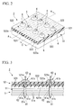
- FIGS. 2 and 3 are diagrams illustrating a spar 2 as the CFRP structure according to the first embodiment, where FIG. 2 is a perspective view schematically illustrating a part of the spar 2 and FIG. 3 is a cross-sectional view schematically illustrating a cross-section taken along line A-A of FIG. 2 .
- the spar 2 includes a spar body 5 formed of CFRP and a plurality of ports 6 detachably attached to the spar body 5.
- the spar body 5 includes a layered carbon-fiber prepreg 51 and a signal-line layer 52 stacked on the surface of the carbon-fiber prepreg 51.
- the carbon-fiber prepreg 51 is formed by stacking a plurality of sheets 51a in which a thermosetting resin (not shown) is made to seep into carbon fiber and curing the thermosetting resin to unify the sheets 51a.
- the carbon-fiber prepreg 51 made of carbon fiber has conductivity.
- a plurality of port insertion holes 51 b are formed in the carbon-fiber prepreg 51 so as to correspond to the positions of signal lines 522 to be described later.
- the port insertion holes 51 b serves to insert the ports 6 therethrough and are formed with a predetermined gap along the extending direction of the signal lines 522 so as to pass through the carbon-fiber prepreg 51.
- the signal-line layer 52 includes a resin layer 521 disposed to cover the surface of the carbon-fiber prepreg 51, a plurality of signal lines 522 embedded in the resin layer 521, and reinforcing fiber 523 embedded in the resin layer 521 between the signal lines 522.
- the resin layer 521 is formed by stacking the thermosetting resin seeping from the carbon fiber at the time of curing the thermosetting resin on the surface of the carbon-fiber prepreg 51.
- the resin layer 521 made of the thermosetting resin is an insulator not having conductivity.
- a plurality of port attachment holes 521 a are formed in the resin layer 521 so as to correspond to the positions of the signal lines 522.
- the port attachment holes 521a are used to attach the ports 6 thereto and are formed to pass through the resin layer 521 with substantially the same gap as the port insertion holes 51 b along the extending direction of the signal lines 522. Accordingly, the port attachment holes 521a communicate with the port insertion holes 51b located on the lower side thereof.
- the plurality of signal lines 522 are electrical lines connected to an electronic device not shown so as to supply power thereto.
- the signal lines 522 has a configuration in which a copper wire 522a is covered with an insulator 522b such as a fluorine resin and are arranged to be parallel to each other with a predetermined gap C.
- the signal lines 522 are not disposed in the port attachment holes 521a formed in the resin layer 521. In a part of signal lines 522 extending in the opposite directions with the corresponding port 6 interposed therebetween, one end of the copper wire 522a is exposed to the inside of the port attachment holes 521a.
- the material, the cross-sectional shape, the length, the number, and the like of the signal lines 522 are not limited to this embodiment and can be appropriately changed in design. Although details are not shown, the signal lines 522 according to the present invention are not limited to the electric lines according to this embodiment but, for example, optical fiber transmitting electrical signals input to an electronic device and output from the electronic device may be used. Where the optical fiber is employed as the signal lines 522, the optical fiber having superior heat resistance can be suitably used so as not to degrade at the time of heating the carbon-fiber prepreg 51.
- the plurality of reinforcing fibers 523 reinforce the resin layer 521 to suppress deformation of the signal lines 522 as much as possible.
- the reinforcing fibers 523 are linear fiber glass (glass fibers). As shown in FIG. 2 , two reinforcing fibers 523 are disposed with a predetermined gap between the neighboring signal lines 522 so as to extend in a direction substantially parallel to the signal lines 522.
- the cross-sectional shape, the length, the number, and the like of the reinforcing fibers 523 are not limited to this embodiment but can be changed in design depending on the thickness of the resin layer 521 or the shape of the signal lines 522.
- the material of the reinforcing fibers 523 is not limited to the fiber glass according to this embodiment, but any member having superior resistance to bending or torsion can be used.
- the reinforcing fibers 523 are not constituents essential to the present invention, and the signal-line layer 52 may be constructed by the resin layer 521 and the plurality of signal lines 522.
- each port 6 includes a bolt-like support 61, a port body 62 supported by the support 61, and a signal drawing line 63 of which one end is connected to the port body 62 and the other end is drawn out to the outside of the support 61.
- an umbrella-like head portion 61b is formed at one end of a rod-like shaft portion 61a and an insertion hole 61c is formed to pass through the shaft portion 61 a and the head portion 61 b.
- the shaft portion 61 a is formed so that the outer diameter thereof is substantially equal to the inner diameter of the port attachment holes 521a and the port insertion holes 51 b and the length thereof is slightly larger than the thickness of the spar body 5.
- the head portion 61b is formed so that the outer diameter thereof is larger than the inner diameter of the port attachment holes 521a.
- the port body 62 has a cross-sectional shape substantially inserted into the port attachment hole 521a of the resin layer 521.
- the port body 62 is inserted into the insertion hole 61c formed through the support 61 and is supported at the position of the support 61 close to the base end of the shaft portion 61 a, that is, at the position close to the head portion 61b.
- the shaft portion 61a of the support 61 is inserted into the port attachment hole 521 a and the port insertion hole 5 1 b up to the position at which the bottom surface of the head portion 61b comes in contact with the surface of the resin layer 521.
- the port body 62 supported by the shaft portion 61a of the support 61 is located inside the port attachment hole 521 a and a pair of signal lines 522 extending to both sides with the port body 62 interposed therebetween is connected to the port body 62. That is, the copper line 522a passing through the signal line 522 comes in contact with the port body 62. Accordingly, it is possible to draw out a signal input to the signal line 522 from the port body 62 to the outside via the signal drawing line 63.
- the spar 2 as the CFRP structure according to the first embodiment a plurality of signal lines 522 connected to an electronic device are embedded in the resin layer 521 stacked on the surface of the carbon-fiber prepreg 51. Accordingly, since the signal lines 522 are not exposed on the surface of the spar 2, it is possible to simplify the configuration of the spar 2 and to reduce the size thereof. It is also possible to prevent the signal lines 522 from being damaged due to contact with external objects (not shown). It is also possible to prevent appearance of the spar 2 from being damaged due to exposure of the signal lines 522.
- the ports 6 passing through the signal-line layer 52 and coming in contact with the signal lines 522 are provided, it is possible to draw out a signal input to the signal lines 522 embedded in the resin layer 521 via the ports 6.
- the ports 6 are detachably attached to the spar body 5. Accordingly, where there are a plurality of types of devices to which the signal drawn out from the signal lines 522 should be input, the ports 6 can be replaced with ports corresponding to the devices.
- the neighboring signal lines 522 are separated from each other with a gap C corresponding to the frequency of an input signal, it is possible to prevent a problem with electromagnetic interference in that a signal line 522 is affected by electromagnetic waves generated from the neighboring signal lines 522 to generate noise in the signal.
- CFRP structure The configuration of a CFRP structure according to a second embodiment of the present invention will be described below.
- members constituting a primary wing of an aircraft will be described as an example of the CFRP structure.
- the primary wing according to the second embodiment includes a pair of spars 2, a pair of panels 3, and a plurality of ribs 4, similarly to the primary wing according to the first embodiment shown in FIG. 1 .
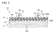
- FIG. 4 is a cross-sectional view schematically illustrating a spar 10 according to the second embodiment.
- the spar 10 according to this embodiment includes a spar body 11 made of a CFRP and a plurality of ports 12 which are fixed to the spar body 11 so as not to be detachable therefrom.
- the spar body 11 is the same as the spar body 11 according to the first embodiment shown in FIG. 3 , in that a signal-line layer 14 is stacked on the surface of a layered carbon-fiber prepreg 13.
- the spar body 11 is different from the spar body 5 according to the first embodiment, in that the port insertion holes 51 b are not formed in the carbon-fiber prepreg 13 and the port attachment holes 521 a are not formed in the resin layer 141 constituting the signal-line layer 14.
- the other configuration of the spar body 11 is the same as described in the first embodiment. Accordingly, the same reference numerals as shown in FIG. 3 are used in FIG. 4 and a description thereof will not be repeated here.
- each of the plurality of ports 12 includes a port body 121 embedded in the resin layer 141 and a signal drawing line 122 of which one end is connected to the port body 121 and the other end is drawn out to the outside of the support 61.
- the port body 121 is an electrode made of titanium or corrosion-resistant steel and used to draw out a signal input to the corresponding signal line 522 to the outside.
- corrosion-resistant steel means alloy steel of which resistance to corrosion is improved to be superior to stainless steel by optimizing the amount of chromium, molybdenum, nickel, or the like.
- the port body 121 is embedded in the resin layer 141 constituting the signal-line layer 14, is fixed to the spar body 11 so as not to be detachable therefrom, and comes in contact with the copper line 522a passing through the signal line 522. Accordingly, it is possible to draw out a signal input to the signal line 522 from the port body 121 to the outside via the signal drawing line 122.
- the operational effects of the spar 10 as the CFRP structure according to the second embodiment will be described below.
- the plurality of signal lines 522 connected to an electronic device are embedded in the resin layer 141 stacked on the surface of the carbon-fiber prepreg 13. Accordingly, the same effects as the spar 2 according to the first embodiment, that is, the simplification in configuration and the reduction in size of the spar 10, the prevention of damage to the signal lines 522, and the improvement in appearance, can be achieved.
- the ports 12 embedded in the resin layer 141 and coming in contact with the signal lines 522 are provided, it is possible to draw out a signal input to the signal lines 522 embedded in the resin layer 141 via the ports 12.
- the ports 12 are fixed to the spar body 11 so as not to be detachable therefrom. Accordingly, since the copper wires 522a passing through the signal lines 522 and the ports 12 are brought into satisfactory contact with each other and are supported in this state, it is possible to accurately and reliably draw out the signal input to the signal lines 522 to the outside.
- the port body 121 By making the port body 121 out of titanium or corrosion-resistant steel, the port body 121 is not likely to be rusted even when the port body 121 fixed to the spar body 11 is present inside the resin layer 141 for long periods of time. Accordingly, it is possible to more accurately and surely drawn out the signal input to the signal lines 522 to the outside.
- the spars 2 and 10 constituting the primary wing 1 of an aircraft are described as an example of the CFRP structure.
- the CFRP structure is not limited to the spars 2 and 10 and may be used, for example, as the top skin 31a and the stringers 31b constituting the top panel 31 shown in FIG. 1 , or the bottom skin 32a and the stringers 32b constituting the bottom panel 32.
- the CFRP structure is not limited to the constituent of the primary wing 1 of an aircraft, but may be a constituent of an arbitrary structure.
- the signal lines are embedded in the resin layer and are not exposed on the surface of the CFRP structure, it is possible to simplify the configuration of the CFRP structure and to reduce the size thereof. It is also possible to prevent the signal lines from being damaged due to contact with external objects. It is also possible to prevent appearance of the CFRP structure from being damaged due to exposure of the signal lines.
Landscapes
- Engineering & Computer Science (AREA)
- Microelectronics & Electronic Packaging (AREA)
- Aviation & Aerospace Engineering (AREA)
- Mechanical Engineering (AREA)
- Manufacturing & Machinery (AREA)
- Laminated Bodies (AREA)
- Moulding By Coating Moulds (AREA)
- Control Of Indicators Other Than Cathode Ray Tubes (AREA)
- Production Of Multi-Layered Print Wiring Board (AREA)
Abstract
Description
- The present invention relates to a carbon-fiber-reinforced plastic structure in which a resin layer is stacked on the surface of a carbon-fiber prepreg.
- Conventionally, structures such as primary wings of an aircraft are generally formed of a metal member such as an aluminum alloy member. However, recently, from the viewpoint of a decrease in weight or an increase in strength, so-called composite materials such as carbon-fiber-reinforced plastics (hereinafter, abbreviated as "CFRP") are widely used as the materials of such structures (for example, see PTL 1).
- Specifically, a carbon-fiber-reinforced plastic structure (hereinafter, abbreviated as a "CFRP structure") having a predetermined shape is formed by heating a carbon-fiber prepreg in which a plurality of sheets having a thermosetting resin infiltrated into a carbon fiber are stacked and curing the thermosetting resin. In the CFRP structure, a so-called resin layer is formed on the surface thereof by the thermosetting resin seeping from the carbon fiber at the time of heating the carbon-fiber prepreg.
- Where an electronic device is installed on the surface of the CFRP structure, a signal line connected to the electronic device is generally arranged to extend on the surface of the CFRP structure.
-
- [PTL 1] Japanese Unexamined Patent Application, First Publication No.
H9-193296 - However, in the conventional CFRP structure, since signal line is arranged to extend on the surface thereof, the configuration of the structure is complicated and the structure increases in size by the thickness of the signal lines. Since the signal line is exposed on the surface of the CFRP structure, the signal line is likely to be damaged due to contact with external objects and appearance of the CFRP structure is damaged.
- The present invention is made in consideration of the above-mentioned circumstances and an object thereof is to provide means for enabling an electronic device to be mounted on a CFRP structure without causing signal lines to extend on the surface thereof.
- A carbon-fiber-reinforced plastic structure according to the present invention includes a carbon-fiber prepreg and a signal-line layer stacked on the carbon-fiber prepreg, wherein the signal-line layer includes a resin layer and a plurality of signal lines embedded in the resin layer.
- According to this configuration, since the signal lines are embedded in the resin layer and are not exposed on the surface of the CFRP structure, it is possible to simplify the CFRP structure and to reduce the size thereof. It is also possible to prevent the signal lines from being damaged due to contact with external objects. It is also possible to prevent appearance of the CFRP structure from being damaged due to exposure of the signal lines.
- In the carbon-fiber-reinforced plastic structure according to the present invention, ports connected to the signal lines through the signal-line layer may be disposed in the middle of the signal lines.
- According to this configuration, signals input to the signal lines can be drawn out to the outside via the ports connected to the signal lines, even though the signal lines are not exposed on the surface of the CFRP structure.
- In the carbon-fiber-reinforced plastic structure according to the present invention, the signal lines may be arranged with a gap corresponding to a frequency of an input signal.
- According to this configuration, since electrostatic capacitance (so-called C) formed between the neighboring signal lines decreases with an increase in the gap between the signal lines and increases with a decrease in the gap, it is possible to maintain electric resistance at a useful frequency, for example, by reducing the value of C with an increase in the useful frequency.
Since the neighboring signal lines are separated from each other by the gap corresponding to the frequency of an input signal, it is possible to prevent a problem with electromagnetic interference in that a signal line is affected by electromagnetic waves generated from the neighboring signal lines thereof to generate noise in the signal. - By employing the carbon-fiber-reinforced plastic structure according to the present invention, it is possible to mount an electronic device on the CFRP structure without causing signal lines to extend on the surface thereof. Accordingly, it is possible to simplify the CFRP structure and to reduce the size thereof. It is also possible to prevent the signal lines from being damaged due to contact with external objects. It is also possible to prevent appearance of the CFRP structure from being damaged due to exposure of the signal lines on the surface of the CFRP structure.
-
-
FIG. 1 is an exploded perspective view schematically illustrating a primary wing according to a first embodiment of the present invention. -
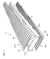
FIG. 2 is a perspective view schematically illustrating a part of a spar according to the first embodiment. -
FIG. 3 is a cross-sectional view schematically illustrating a cross-section taken along line A-A ofFIG. 2 . -
FIG. 4 is a cross-sectional view schematically illustrating a spar according to a second embodiment. - Hereinafter, embodiments of the present invention will be described with reference to the accompanying drawings. First, the configuration of a CFRP structure according to a first embodiment of the present invention will be described. A member constituting a primary wing of an aircraft will be described as an example of the CFRP structure.
-
FIG. 1 is an exploded perspective view schematically illustrating the configuration of a primary wing 1. The primary wing 1 includes a pair ofspars 2 forming both side portions along the longitudinal direction, a pair ofpanels 3 forming a top surface and a bottom surface, and a plurality ofribs 4 disposed therein. - As shown in
FIG. 1 , the pair ofspars 2 includes afront spar 21 constituting a side portion on the front side of an aircraft out of both side portions of the primary wing 1 and arear spar 22 constituting a side portion on the rear side of the aircraft. The pair ofspars 2 having this configuration is disposed with a predetermined gap therebetween so that each opening thereof faces each other. Both the front spar 21 and therear spar 22 are members formed by shaping a carbon-fiber-reinforced plastic (CFRP). - As shown in
FIG. 1 , the pair ofpanels 3 includes atop panel 31 constituting the top surface of the primary wing 1 and abottom panel 32 constituting the bottom surface thereof. Thetop panel 31 includes a plate-liketop skin 31a having a curved cross-sectional shape and a plurality ofstringers 31b disposed on one surface of thetop skin 31 a so as to enhance the bending stiffness of thetop skin 31 a. Thetop skin 31a and thestringers 31b are also members formed by shaping a carbon-fiber-reinforced plastic. Similarly, thebottom panel 32 includes abottom skin 32a and a plurality ofstringers 32b, and both are also members formed by shaping a carbon-fiber-reinforced plastic. - The plurality of
ribs 4 structurally reinforce the primary wing 1. As shown inFIG. 1 , theribs 4 are arranged with a predetermined gap in the longitudinal direction of the primary wing 1 and one end of eachrib 4 is connected to thefront spar 21 and the other end thereof is connected to therear spar 22. Accordingly, the front spar 21 and therear spar 22 are maintained with a constant gap. Theribs 4 are members formed of metal. -
FIGS. 2 and 3 are diagrams illustrating aspar 2 as the CFRP structure according to the first embodiment, whereFIG. 2 is a perspective view schematically illustrating a part of thespar 2 andFIG. 3 is a cross-sectional view schematically illustrating a cross-section taken along line A-A ofFIG. 2 . - As shown in
FIGS. 2 and 3 , thespar 2 includes aspar body 5 formed of CFRP and a plurality ofports 6 detachably attached to thespar body 5. - As shown in
FIG. 3 , thespar body 5 includes a layered carbon-fiber prepreg 51 and a signal-line layer 52 stacked on the surface of the carbon-fiber prepreg 51. - As shown in
FIG. 3 , the carbon-fiber prepreg 51 is formed by stacking a plurality ofsheets 51a in which a thermosetting resin (not shown) is made to seep into carbon fiber and curing the thermosetting resin to unify thesheets 51a. Here, the carbon-fiber prepreg 51 made of carbon fiber has conductivity. As shown inFIG. 2 , a plurality ofport insertion holes 51 b are formed in the carbon-fiber prepreg 51 so as to correspond to the positions ofsignal lines 522 to be described later. Theport insertion holes 51 b serves to insert theports 6 therethrough and are formed with a predetermined gap along the extending direction of thesignal lines 522 so as to pass through the carbon-fiber prepreg 51. - As shown in
FIGS. 2 and 3 , the signal-line layer 52 includes aresin layer 521 disposed to cover the surface of the carbon-fiber prepreg 51, a plurality ofsignal lines 522 embedded in theresin layer 521, and reinforcingfiber 523 embedded in theresin layer 521 between thesignal lines 522. - The
resin layer 521 is formed by stacking the thermosetting resin seeping from the carbon fiber at the time of curing the thermosetting resin on the surface of the carbon-fiber prepreg 51. Theresin layer 521 made of the thermosetting resin is an insulator not having conductivity. As shown inFIG. 3 , a plurality ofport attachment holes 521 a are formed in theresin layer 521 so as to correspond to the positions of thesignal lines 522. Theport attachment holes 521a are used to attach theports 6 thereto and are formed to pass through theresin layer 521 with substantially the same gap as theport insertion holes 51 b along the extending direction of thesignal lines 522. Accordingly, theport attachment holes 521a communicate with theport insertion holes 51b located on the lower side thereof. - The plurality of
signal lines 522 are electrical lines connected to an electronic device not shown so as to supply power thereto. As shown inFIG. 2 , thesignal lines 522 has a configuration in which acopper wire 522a is covered with aninsulator 522b such as a fluorine resin and are arranged to be parallel to each other with a predetermined gap C. The signal lines 522 are not disposed in theport attachment holes 521a formed in theresin layer 521. In a part ofsignal lines 522 extending in the opposite directions with thecorresponding port 6 interposed therebetween, one end of thecopper wire 522a is exposed to the inside of theport attachment holes 521a. - The material, the cross-sectional shape, the length, the number, and the like of the
signal lines 522 are not limited to this embodiment and can be appropriately changed in design. Although details are not shown, thesignal lines 522 according to the present invention are not limited to the electric lines according to this embodiment but, for example, optical fiber transmitting electrical signals input to an electronic device and output from the electronic device may be used. Where the optical fiber is employed as thesignal lines 522, the optical fiber having superior heat resistance can be suitably used so as not to degrade at the time of heating the carbon-fiber prepreg 51. - The plurality of reinforcing
fibers 523 reinforce theresin layer 521 to suppress deformation of thesignal lines 522 as much as possible. The reinforcingfibers 523 are linear fiber glass (glass fibers). As shown inFIG. 2 , two reinforcingfibers 523 are disposed with a predetermined gap between theneighboring signal lines 522 so as to extend in a direction substantially parallel to the signal lines 522. - The cross-sectional shape, the length, the number, and the like of the reinforcing
fibers 523 are not limited to this embodiment but can be changed in design depending on the thickness of theresin layer 521 or the shape of the signal lines 522. The material of the reinforcingfibers 523 is not limited to the fiber glass according to this embodiment, but any member having superior resistance to bending or torsion can be used. The reinforcingfibers 523 are not constituents essential to the present invention, and the signal-line layer 52 may be constructed by theresin layer 521 and the plurality of signal lines 522. - The plurality of
ports 6 are electrodes for drawing out signals input to thesignal lines 522 to the outside. As shown inFIG. 3 , eachport 6 includes a bolt-like support 61, aport body 62 supported by thesupport 61, and asignal drawing line 63 of which one end is connected to theport body 62 and the other end is drawn out to the outside of thesupport 61. - As shown in
FIG. 3 , in thesupport 61, an umbrella-like head portion 61b is formed at one end of a rod-like shaft portion 61a and aninsertion hole 61c is formed to pass through theshaft portion 61 a and thehead portion 61 b. Here, theshaft portion 61 a is formed so that the outer diameter thereof is substantially equal to the inner diameter of the port attachment holes 521a and the port insertion holes 51 b and the length thereof is slightly larger than the thickness of thespar body 5. Thehead portion 61b is formed so that the outer diameter thereof is larger than the inner diameter of theport attachment holes 521a. - As shown in
FIG. 3 , theport body 62 has a cross-sectional shape substantially inserted into theport attachment hole 521a of theresin layer 521. Theport body 62 is inserted into theinsertion hole 61c formed through thesupport 61 and is supported at the position of thesupport 61 close to the base end of theshaft portion 61 a, that is, at the position close to thehead portion 61b. - As shown in
FIG. 3 , in theport 6 having this configuration, theshaft portion 61a of thesupport 61 is inserted into theport attachment hole 521 a and theport insertion hole 5 1 b up to the position at which the bottom surface of thehead portion 61b comes in contact with the surface of theresin layer 521. At this time, theport body 62 supported by theshaft portion 61a of thesupport 61 is located inside theport attachment hole 521 a and a pair ofsignal lines 522 extending to both sides with theport body 62 interposed therebetween is connected to theport body 62. That is, thecopper line 522a passing through thesignal line 522 comes in contact with theport body 62. Accordingly, it is possible to draw out a signal input to thesignal line 522 from theport body 62 to the outside via thesignal drawing line 63. - The operational effects of the
spar 2 as the CFRP structure according to the first embodiment will be described below. In thespar 2 according to the first embodiment, a plurality ofsignal lines 522 connected to an electronic device are embedded in theresin layer 521 stacked on the surface of the carbon-fiber prepreg 51. Accordingly, since thesignal lines 522 are not exposed on the surface of thespar 2, it is possible to simplify the configuration of thespar 2 and to reduce the size thereof. It is also possible to prevent thesignal lines 522 from being damaged due to contact with external objects (not shown). It is also possible to prevent appearance of thespar 2 from being damaged due to exposure of the signal lines 522. - Since the
ports 6 passing through the signal-line layer 52 and coming in contact with thesignal lines 522 are provided, it is possible to draw out a signal input to thesignal lines 522 embedded in theresin layer 521 via theports 6. Theports 6 are detachably attached to thespar body 5. Accordingly, where there are a plurality of types of devices to which the signal drawn out from thesignal lines 522 should be input, theports 6 can be replaced with ports corresponding to the devices. - Since the neighboring
signal lines 522 are separated from each other with a gap C corresponding to the frequency of an input signal, it is possible to prevent a problem with electromagnetic interference in that asignal line 522 is affected by electromagnetic waves generated from the neighboringsignal lines 522 to generate noise in the signal. - The configuration of a CFRP structure according to a second embodiment of the present invention will be described below. In this embodiment, members constituting a primary wing of an aircraft will be described as an example of the CFRP structure.
- The primary wing according to the second embodiment includes a pair of
spars 2, a pair ofpanels 3, and a plurality ofribs 4, similarly to the primary wing according to the first embodiment shown inFIG. 1 . -
FIG. 4 is a cross-sectional view schematically illustrating aspar 10 according to the second embodiment. Thespar 10 according to this embodiment includes aspar body 11 made of a CFRP and a plurality ofports 12 which are fixed to thespar body 11 so as not to be detachable therefrom. - As shown in
FIG. 4 , thespar body 11 is the same as thespar body 11 according to the first embodiment shown inFIG. 3 , in that a signal-line layer 14 is stacked on the surface of a layered carbon-fiber prepreg 13. However, thespar body 11 is different from thespar body 5 according to the first embodiment, in that the port insertion holes 51 b are not formed in the carbon-fiber prepreg 13 and the port attachment holes 521 a are not formed in theresin layer 141 constituting the signal-line layer 14. The other configuration of thespar body 11 is the same as described in the first embodiment. Accordingly, the same reference numerals as shown inFIG. 3 are used inFIG. 4 and a description thereof will not be repeated here. - As shown in
FIG. 4 , each of the plurality ofports 12 includes aport body 121 embedded in theresin layer 141 and asignal drawing line 122 of which one end is connected to theport body 121 and the other end is drawn out to the outside of thesupport 61. - The
port body 121 is an electrode made of titanium or corrosion-resistant steel and used to draw out a signal input to thecorresponding signal line 522 to the outside. In this specification, corrosion-resistant steel means alloy steel of which resistance to corrosion is improved to be superior to stainless steel by optimizing the amount of chromium, molybdenum, nickel, or the like. As shown inFIG. 4 , theport body 121 is embedded in theresin layer 141 constituting the signal-line layer 14, is fixed to thespar body 11 so as not to be detachable therefrom, and comes in contact with thecopper line 522a passing through thesignal line 522. Accordingly, it is possible to draw out a signal input to thesignal line 522 from theport body 121 to the outside via thesignal drawing line 122. - The operational effects of the
spar 10 as the CFRP structure according to the second embodiment will be described below. In thespar 10 according to the second embodiment, the plurality ofsignal lines 522 connected to an electronic device are embedded in theresin layer 141 stacked on the surface of the carbon-fiber prepreg 13.
Accordingly, the same effects as thespar 2 according to the first embodiment, that is, the simplification in configuration and the reduction in size of thespar 10, the prevention of damage to thesignal lines 522, and the improvement in appearance, can be achieved. - Since the
ports 12 embedded in theresin layer 141 and coming in contact with thesignal lines 522 are provided, it is possible to draw out a signal input to thesignal lines 522 embedded in theresin layer 141 via theports 12. Theports 12 are fixed to thespar body 11 so as not to be detachable therefrom. Accordingly, since thecopper wires 522a passing through thesignal lines 522 and theports 12 are brought into satisfactory contact with each other and are supported in this state, it is possible to accurately and reliably draw out the signal input to thesignal lines 522 to the outside. - By making the
port body 121 out of titanium or corrosion-resistant steel, theport body 121 is not likely to be rusted even when theport body 121 fixed to thespar body 11 is present inside theresin layer 141 for long periods of time. Accordingly, it is possible to more accurately and surely drawn out the signal input to thesignal lines 522 to the outside. - In the above-mentioned embodiments, the
spars spars top skin 31a and thestringers 31b constituting thetop panel 31 shown inFIG. 1 , or thebottom skin 32a and thestringers 32b constituting thebottom panel 32. The CFRP structure is not limited to the constituent of the primary wing 1 of an aircraft, but may be a constituent of an arbitrary structure. - Various shapes or combinations or operation sequences of the constituent members described in the above-mentioned embodiments are only an example, and can be modified in various forms depending on requirements in design without departing from the concept of the present invention.
- In the carbon-fiber-reinforced plastic structure according to the present invention, since the signal lines are embedded in the resin layer and are not exposed on the surface of the CFRP structure, it is possible to simplify the configuration of the CFRP structure and to reduce the size thereof. It is also possible to prevent the signal lines from being damaged due to contact with external objects. It is also possible to prevent appearance of the CFRP structure from being damaged due to exposure of the signal lines.
-
- 1:
- primary wing
- 2:
- spar (first embodiment)
- 3:
- panel
- 4:
- rib
- 5:
- spar body
- 6:
- port
- 10:
- spar (second embodiment)
- 11:
- spar body
- 12:
- port
- 13:
- carbon-fiber prepreg
- 14:
- signal-line layer
- 21:
- front spar
- 22:
- rear spar
- 31:
- top panel
- 32:
- bottom panel
- 51:
- carbon-fiber prepreg
- 52:
- signal-line layer
- 61:
- support
- 62:
- port body
- 63:
- signal drawing line
- 121:
- port body
- 122:
- signal drawing line
- 141:
- resin layer
- 521:
- resin layer
- 522:
- signal line
- 523:
- reinforcing fiber
- 31a:
- top skin
- 31b:
- stringer
- 32a:
- bottom skin
- 32b:
- stringer
- 51a:
- sheet
- 51b:
- port insertion hole
- 521a:
- port attachment hole
- 522a:
- copper wire
- 522b:
- insulator
- 61a:
- shaft portion
- 61b:
- head portion
- 61c:
- insertion hole
- C:
- gap
Claims (3)
- A carbon-fiber-reinforced plastic structure comprising:a carbon-fiber prepreg; anda signal-line layer stacked on the carbon-fiber prepreg,wherein the signal-line layer includes a resin layer and a plurality of signal lines embedded in the resin layer.
- The carbon-fiber-reinforced plastic structure according to claim 1, wherein ports connected to the signal lines through the signal-line layer are disposed in the middle of the signal lines.
- The carbon-fiber-reinforced plastic structure according to claim 1 or 2, wherein the signal lines are arranged with a gap corresponding to a frequency of an input signal.
Applications Claiming Priority (2)
| Application Number | Priority Date | Filing Date | Title |
|---|---|---|---|
| JP2011030886A JP5730057B2 (en) | 2011-02-16 | 2011-02-16 | Carbon fiber reinforced plastic structure |
| PCT/JP2012/052845 WO2012111503A1 (en) | 2011-02-16 | 2012-02-08 | Carbon-fiber-reinforced plastic structure |
Publications (2)
| Publication Number | Publication Date |
|---|---|
| EP2677844A1 true EP2677844A1 (en) | 2013-12-25 |
| EP2677844A4 EP2677844A4 (en) | 2016-12-07 |
Family
ID=46672428
Family Applications (1)
| Application Number | Title | Priority Date | Filing Date |
|---|---|---|---|
| EP12746610.0A Withdrawn EP2677844A4 (en) | 2011-02-16 | 2012-02-08 | CARBON FIBER REINFORCED PLASTIC STRUCTURE |
Country Status (4)
| Country | Link |
|---|---|
| US (1) | US10357938B2 (en) |
| EP (1) | EP2677844A4 (en) |
| JP (1) | JP5730057B2 (en) |
| WO (1) | WO2012111503A1 (en) |
Families Citing this family (4)
| Publication number | Priority date | Publication date | Assignee | Title |
|---|---|---|---|---|
| JP5773679B2 (en) | 2011-02-16 | 2015-09-02 | 三菱重工業株式会社 | Carbon fiber reinforced plastic structure and manufacturing method thereof |
| DE102014206861A1 (en) * | 2014-04-09 | 2015-10-15 | MAHLE Behr GmbH & Co. KG | Temperature control device for an electrical energy supply unit |
| EP3247933A4 (en) | 2015-01-22 | 2018-10-24 | Neptune Research, Llc | Composite reinforcement systems and methods of manufacturing the same |
| FR3065441B1 (en) * | 2017-04-19 | 2019-07-05 | Airbus Operations | AIRCRAFT ASSEMBLY COMPRISING A PRIMARY STRUCTURE OF A COUPLING MAT FIXED TO A SAILBOX USING A BOLT CONNECTION |
Family Cites Families (11)
| Publication number | Priority date | Publication date | Assignee | Title |
|---|---|---|---|---|
| CN1140430A (en) * | 1994-01-26 | 1997-01-15 | 安普-阿克佐·林莱姆·沃福 | Composite laminate manufacturing method and printed wiring board substrate made therefrom |
| US5866272A (en) * | 1996-01-11 | 1999-02-02 | The Boeing Company | Titanium-polymer hybrid laminates |
| JP4119205B2 (en) * | 2002-08-27 | 2008-07-16 | 富士通株式会社 | Multilayer wiring board |
| US20040190274A1 (en) * | 2003-03-27 | 2004-09-30 | Yoshio Saito | Compact low cost plastic MCM to PCB |
| JP2006024640A (en) * | 2004-07-06 | 2006-01-26 | Fujitsu Ltd | Multilayer circuit board |
| JP4907216B2 (en) * | 2006-04-19 | 2012-03-28 | 三菱電機株式会社 | Printed wiring board and printed wiring board manufacturing method |
| US8148647B2 (en) | 2006-08-23 | 2012-04-03 | Mitsubishi Electric Corporation | Printed circuit board and method of manufacturing the same |
| JP4656156B2 (en) | 2008-01-22 | 2011-03-23 | ソニー株式会社 | Optical communication device |
| JP5200683B2 (en) * | 2008-06-17 | 2013-06-05 | 富士通株式会社 | Wiring board and manufacturing method thereof |
| JP5251395B2 (en) * | 2008-09-24 | 2013-07-31 | 富士通株式会社 | Multilayer wiring board, probe card, and method for manufacturing multilayer wiring board |
| KR101148628B1 (en) * | 2008-11-20 | 2012-05-25 | 후지쯔 가부시끼가이샤 | Wiring board and method for producing wiring board |
-
2011
- 2011-02-16 JP JP2011030886A patent/JP5730057B2/en not_active Expired - Fee Related
-
2012
- 2012-02-08 EP EP12746610.0A patent/EP2677844A4/en not_active Withdrawn
- 2012-02-08 US US13/982,295 patent/US10357938B2/en active Active
- 2012-02-08 WO PCT/JP2012/052845 patent/WO2012111503A1/en not_active Ceased
Non-Patent Citations (1)
| Title |
|---|
| See references of WO2012111503A1 * |
Also Published As
| Publication number | Publication date |
|---|---|
| US10357938B2 (en) | 2019-07-23 |
| JP2012169533A (en) | 2012-09-06 |
| WO2012111503A1 (en) | 2012-08-23 |
| EP2677844A4 (en) | 2016-12-07 |
| JP5730057B2 (en) | 2015-06-03 |
| US20130316128A1 (en) | 2013-11-28 |
Similar Documents
| Publication | Publication Date | Title |
|---|---|---|
| US10272770B2 (en) | Carbon-fiber-reinforced plastic structure and fuel tank | |
| US8004815B2 (en) | Lightning protection system and an aircraft having such a system | |
| US10357938B2 (en) | Carbon-fiber-reinforced plastic structure | |
| US8276848B2 (en) | Rib structure for torsion boxes of a wing or horizontal stabiliser of an aircraft | |
| US8967540B2 (en) | Anti lateral-torsional buckling structural member of an aircraft fuselage | |
| US10815002B2 (en) | Structural component of aircraft wing body and aircraft including the structural component | |
| US8794572B2 (en) | Air intake of an aircraft nacelle that incorporates a reinforced lip with a defrost system by joule-effect | |
| US8628041B2 (en) | Method for realization of an aircraft structure and resulting structure | |
| EP3095691A1 (en) | Multi-spar torsion box structure | |
| US10259557B2 (en) | Pressure bulkhead for an aircraft fuselage, and an aircraft comprising such a pressure bulkhead | |
| US10061270B2 (en) | Pointer and pointer manufacturing method | |
| US11511847B2 (en) | Skin panel of composite material having an internal grid | |
| EP3103623B1 (en) | Composite material structure, aircraft wing and aircraft fuselage provided with same, and method for manufacturing composite material structure | |
| CN113382924A (en) | Antenna assembly, vertical tail, horizontal tail, wing, aircraft and method | |
| US20140377500A1 (en) | Composite structure, aircraft wing and aircraft fuselage including composite structure, and method of manufacturing composite structure | |
| US11498656B1 (en) | Airfoil system with embedded electric device | |
| EP3418922A1 (en) | Structure designing method and structure | |
| EP2749161B1 (en) | Fishing line guide | |
| US20130032670A1 (en) | Wall component for an aircraft | |
| US20170028947A1 (en) | Vehicle fairing including an electrical routing | |
| EP2565117A1 (en) | A stiffening element for an aircraft | |
| WO2019026350A1 (en) | Landing gear for rotary-wing aircraft | |
| EP2681113B1 (en) | Door frame construction, fuselage portion and aircraft or spacecraft | |
| EP3539881B1 (en) | Composite structure, aircraft, and lightning current guiding method | |
| EP4082894B1 (en) | Airfoil system with embedded electric device |
Legal Events
| Date | Code | Title | Description |
|---|---|---|---|
| PUAI | Public reference made under article 153(3) epc to a published international application that has entered the european phase |
Free format text: ORIGINAL CODE: 0009012 |
|
| 17P | Request for examination filed |
Effective date: 20130729 |
|
| AK | Designated contracting states |
Kind code of ref document: A1 Designated state(s): AL AT BE BG CH CY CZ DE DK EE ES FI FR GB GR HR HU IE IS IT LI LT LU LV MC MK MT NL NO PL PT RO RS SE SI SK SM TR |
|
| DAX | Request for extension of the european patent (deleted) | ||
| RA4 | Supplementary search report drawn up and despatched (corrected) |
Effective date: 20161108 |
|
| RIC1 | Information provided on ipc code assigned before grant |
Ipc: H05K 3/46 20060101ALI20161031BHEP Ipc: H05K 1/03 20060101AFI20161031BHEP Ipc: G09G 3/20 20060101ALI20161031BHEP Ipc: H05K 1/11 20060101ALN20161031BHEP |
|
| STAA | Information on the status of an ep patent application or granted ep patent |
Free format text: STATUS: EXAMINATION IS IN PROGRESS |
|
| 17Q | First examination report despatched |
Effective date: 20190328 |
|
| STAA | Information on the status of an ep patent application or granted ep patent |
Free format text: STATUS: THE APPLICATION IS DEEMED TO BE WITHDRAWN |
|
| 18D | Application deemed to be withdrawn |
Effective date: 20210901 |