EP2677239A1 - Method for operating a two stage gas turbine combustion chamber - Google Patents
Method for operating a two stage gas turbine combustion chamber Download PDFInfo
- Publication number
- EP2677239A1 EP2677239A1 EP12172629.3A EP12172629A EP2677239A1 EP 2677239 A1 EP2677239 A1 EP 2677239A1 EP 12172629 A EP12172629 A EP 12172629A EP 2677239 A1 EP2677239 A1 EP 2677239A1
- Authority
- EP
- European Patent Office
- Prior art keywords
- temperature
- fuel
- fuel supply
- flame
- combustion chamber
- Prior art date
- Legal status (The legal status is an assumption and is not a legal conclusion. Google has not performed a legal analysis and makes no representation as to the accuracy of the status listed.)
- Withdrawn
Links
Images

Classifications
-
- F—MECHANICAL ENGINEERING; LIGHTING; HEATING; WEAPONS; BLASTING
- F23—COMBUSTION APPARATUS; COMBUSTION PROCESSES
- F23R—GENERATING COMBUSTION PRODUCTS OF HIGH PRESSURE OR HIGH VELOCITY, e.g. GAS-TURBINE COMBUSTION CHAMBERS
- F23R3/00—Continuous combustion chambers using liquid or gaseous fuel
- F23R3/28—Continuous combustion chambers using liquid or gaseous fuel characterised by the fuel supply
- F23R3/286—Continuous combustion chambers using liquid or gaseous fuel characterised by the fuel supply having fuel-air premixing devices
-
- F—MECHANICAL ENGINEERING; LIGHTING; HEATING; WEAPONS; BLASTING
- F23—COMBUSTION APPARATUS; COMBUSTION PROCESSES
- F23R—GENERATING COMBUSTION PRODUCTS OF HIGH PRESSURE OR HIGH VELOCITY, e.g. GAS-TURBINE COMBUSTION CHAMBERS
- F23R3/00—Continuous combustion chambers using liquid or gaseous fuel
- F23R3/28—Continuous combustion chambers using liquid or gaseous fuel characterised by the fuel supply
- F23R3/34—Feeding into different combustion zones
- F23R3/346—Feeding into different combustion zones for staged combustion
-
- F—MECHANICAL ENGINEERING; LIGHTING; HEATING; WEAPONS; BLASTING
- F23—COMBUSTION APPARATUS; COMBUSTION PROCESSES
- F23C—METHODS OR APPARATUS FOR COMBUSTION USING FLUID FUEL OR SOLID FUEL SUSPENDED IN A CARRIER GAS OR AIR
- F23C2900/00—Special features of, or arrangements for combustion apparatus using fluid fuels or solid fuels suspended in air; Combustion processes therefor
- F23C2900/07002—Premix burners with air inlet slots obtained between offset curved wall surfaces, e.g. double cone burners
Definitions
- the present disclosure relates to a method for operating a combustion device.
- the combustion device is preferably a combustion device of a gas turbine.
- EP 2 434 222 discloses a combustion device having a combustion chamber connected to a plurality of burners.
- the burners are divided in two groups, namely:
- This structure for the combustion device and this operating concept allow a broad operating window for the gas turbine.
- the inventors have found a method for operating a combustion device having the features above described, which permits operation with low NOx emissions.
- An aspect of the disclosure includes providing a method for operating a combustion device generating low NOx emissions.
- the NOx emissions generated while operating the first fuel supply to generate a flame at a first temperature and the second fuel supply to generate a flame at a second temperature are lower than the NOx emissions generated when operating a combustion device with all fuel supplies that generate flames at a temperature being the average of the first and second temperature.
- This combustion device 1 has a combustion chamber 2 with at least a first fuel supply 3 and a second fuel supply 4.
- the first fuel supply 3 can for example include one or more fuel supplies, such as premixed fuel supplies.
- the premixed fuel supplies include conic shells defining substantially conic swirl chambers and slots between adjacent shells. Adjacent to the slots, fuel pipes are provided; these pipes have injectors for the fuel.
- an air stream is introduced into the swirl chambers through the slots and fuel (gas or liquid fuel) is injected into the air stream via the pipes and their injectors.
- the second fuel supply 4 can include one or more fuel supplies, such as premixed fuel supplies.
- the fuel supplies can have conical shells with slots for air and pipes with injectors for fuel, as above described.
- Reference 5 indicates the gas turbine longitudinal axis; as shown, the first fuel supply 3 is axially upstream of the second fuel supply 4 (i.e. the fuel supply 3 is upstream of the second fuel supply 4 along the axis 5).
- the first and second fuel supplies 3, 4 can be arranged in different ways and for example they can be:
- the fuel injected via the first fuel supply 3 generates a flame 7 having a first temperature T1.
- the fuel injected via the second fuel supply 4 generates a flame 8 having a second temperature T2.
- the second temperature is higher than the first temperature.
- This temperature regulation allows a reduction of the NOx emissions when compared to the emissions of a gas turbine operating at a temperature between the first and second temperature and generating the same power output.
- NOx generation in a combustion device largely depends on the flame temperature and residence time within the combustion chamber 2. Namely the higher the flame temperature the higher the NOx generation ( figure 2 ) and likewise the higher the residence time in the combustion chamber the higher the NOx generation (thermal NOx, figure 3 ) .
- Figure 3 also shows the NOx generated by a combustion chamber having all fuel supplies:
- the NOx generated in the first case is smaller than the NOx generated in the second case.
- the flame temperature T2 at the second fuel supply 4 can be reduced, while operating the second fuel supply far from the lean blow off conditions.
- the load can be increased by increasing the flame temperature T1 at the first fuel supply 3; in this case regulation brings the first fuel supply 3 farther from the lean blow off conditions.
Landscapes
- Engineering & Computer Science (AREA)
- Chemical & Material Sciences (AREA)
- Combustion & Propulsion (AREA)
- Mechanical Engineering (AREA)
- General Engineering & Computer Science (AREA)
Abstract
The disclosure refers to a method for operating a combustion device (1). The combustion device (1) includes a combustion chamber (2), a first fuel supply (3) connected to the combustion chamber (2) and a second fuel supply (4) connected to the combustion chamber (2). The first fuel supply (3) is upstream of the second fuel supply (4). The method comprises injecting a fuel via the first supply (3) and combusting it generating a flame (7) having a first temperature and injecting a fuel via the second supply (4) and combusting it generating a flame (8) having a second temperature. The second temperature is higher than the first temperature.
Description
- The present disclosure relates to a method for operating a combustion device.
- The combustion device is preferably a combustion device of a gas turbine.
-
EP 2 434 222 - the burners of a first group are positioned axially upstream of the burners of a second groups, and
- the burners of the first group are operated such that they generate a flame having a temperature higher than the temperature of the flame generated by the burners of the second group.
- This structure for the combustion device and this operating concept allow a broad operating window for the gas turbine.
- During operation of a gas turbine NOx emissions are always an issue, because the NOx emissions must be below a prefixed limit that is usually given by the law.
- The inventors have found a method for operating a combustion device having the features above described, which permits operation with low NOx emissions.
- An aspect of the disclosure includes providing a method for operating a combustion device generating low NOx emissions.
- These and further aspects are attained by providing a method in accordance with the attached claims.
- Advantageously, according to the method the NOx emissions generated while operating the first fuel supply to generate a flame at a first temperature and the second fuel supply to generate a flame at a second temperature, are lower than the NOx emissions generated when operating a combustion device with all fuel supplies that generate flames at a temperature being the average of the first and second temperature.
- Further characteristics and advantages will be more apparent from the description of a preferred but non-exclusive embodiment of the method illustrated by way of non-limiting example in the accompanying drawings, in which:
-
Figure 1 is a schematic view of a combustion chamber that can implement the method; -
Figure 2 shows the relationship between NOx and Tf (flame temperature); -
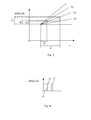
Figure 3 shows the relationship between dNOx/dt and t (time); and -
Figure 4 shows the total dNOx/dt that causes NOx generation. - With reference to
figure 1 and example of a combustion device that can be used to implement the invention is shown. - This
combustion device 1 has acombustion chamber 2 with at least afirst fuel supply 3 and a second fuel supply 4. - The
first fuel supply 3 can for example include one or more fuel supplies, such as premixed fuel supplies. - In a preferred example, the premixed fuel supplies include conic shells defining substantially conic swirl chambers and slots between adjacent shells. Adjacent to the slots, fuel pipes are provided; these pipes have injectors for the fuel.
- During operation, an air stream is introduced into the swirl chambers through the slots and fuel (gas or liquid fuel) is injected into the air stream via the pipes and their injectors.
- Air and fuel mix to then enter the combustion chamber where the fuel is combusted (premixed combustion).
- Likewise, the second fuel supply 4 can include one or more fuel supplies, such as premixed fuel supplies.
- Also in this case, the fuel supplies can have conical shells with slots for air and pipes with injectors for fuel, as above described.
-
Reference 5 indicates the gas turbine longitudinal axis; as shown, thefirst fuel supply 3 is axially upstream of the second fuel supply 4 (i.e. thefuel supply 3 is upstream of the second fuel supply 4 along the axis 5). - The first and
second fuel supplies 3, 4 can be arranged in different ways and for example they can be: - radially shifted (as shown in
figure 1 ); in this case thefirst fuel supply 3 can be closer to or farther from theaxis 5 than the second fuel supply 4; - circumferentially shifted; for example one or more
first fuel supplies 3 can be alternated to one or more second fuel supplies 4; - both.
- During operation, the fuel injected via the
first fuel supply 3 generates aflame 7 having a first temperature T1. Likewise the fuel injected via the second fuel supply 4 generates aflame 8 having a second temperature T2. - According to the method, the second temperature is higher than the first temperature.
- This temperature regulation allows a reduction of the NOx emissions when compared to the emissions of a gas turbine operating at a temperature between the first and second temperature and generating the same power output.
- In fact, NOx generation in a combustion device largely depends on the flame temperature and residence time within the
combustion chamber 2. Namely the higher the flame temperature the higher the NOx generation (figure 2 ) and likewise the higher the residence time in the combustion chamber the higher the NOx generation (thermal NOx,figure 3 ) . - With reference to
figure 3 : - the first flame has a temperature T1 and generates hot gases that pass through the
combustion chamber 2 with a residence time t1 (i.e. the hot gases need the time t1 to pass through the combustion chamber 2); the flame at the temperature T1 with hot gases generated by it having a residence time t1 has a differential NOx generation over time (dNOx/dt) A; - the second flame has a temperature T2 and generates hot gases that pass through the
combustion chamber 2 with a residence time t2 (i.e. the hot gases need the time t2 to pass through thecombustion chamber 2; t2 is smaller than t1 because the second fuel supply 4 is axially downstream of the first fuel supply 3); the flame at the temperature T2 with hot gases generated by it having a residence time t2 has a differential NOx generation over time (dNOx/dt) B. - Thus the total differential NOx generation over time (dNOx/dt) is A+B (as shown in
figure 4 ). -
Figure 3 also shows the NOx generated by a combustion chamber having all fuel supplies: - at the same axial position,
- generating flames at a temperature T3 being the average of the temperatures T1 and T2,
- generating hot gases having a residence time t1.
- From
figure 3 it is apparent that the differential NOx generation is in this case C and fromfigure 4 it can be seen that C is greater than A+B. - Since the NOx actually generated in the combustion chamber is the integral of A+B (in the first case) and C (in the second case), the NOx generated in the first case is smaller than the NOx generated in the second case.
- Likewise, even considering a
combustion chamber 2 like the one shown atfigure 1 , it appears that when the first andsecond fuel supplies 3 and 4 operate generating flame at the temperature T3 being the average of the temperatures T1 and T2, the differential NOx generation (dNOx/dt) and therefore also the NOx generation are greater than in case: - the first flame has a temperature T1,
- the second flame has a temperature T2,
- the temperature T3 is the average of the temperatures T1 and T2.
- Advantageously, according to the method of the present disclosure it is possible the load regulation while keeping the NOx and hydro carbon non-combusted components at a low level.
- In fact, in order to reduce the load, the flame temperature T2 at the second fuel supply 4 can be reduced, while operating the second fuel supply far from the lean blow off conditions.
- Likewise, the load can be increased by increasing the flame temperature T1 at the
first fuel supply 3; in this case regulation brings thefirst fuel supply 3 farther from the lean blow off conditions. - Naturally the features described may be independently provided from one another.
- In practice the materials used and the dimensions can be chosen at will according to requirements and to the state of the art.
-
- 1 combustion device
- 2 combustion chamber
- 3 first fuel supply
- 4 second fuel supply
- 5 axis
- 7 first flame
- 8 second flame
- Tf flame temperature
- A dNOx/dt at temperature T2
- B dNOx/dt at temperature T1
- C dNOx/dt at temperature T3
- t1 residence time for hot gases generated by the flame generated at the first fuel supply
- t2 residence time for hot gases generated by the flame generated at the second fuel supply
Claims (8)
- A method for operating a combustion device (1), the combustion device (1) including
a combustion chamber (2),
at least a first fuel supply (3) connected to the combustion chamber (2),
at least a second fuel supply (4) connected to the combustion chamber (2),
the first fuel supply (3) being upstream of the second fuel supply (4),
the method comprising
injecting a fuel via the at least a first supply (3) and combusting it generating a flame (7) having a first temperature (T1),
injecting a fuel via the at least a second supply (4) and combusting it generating a flame (8) having a second temperature (T2),
characterised in that the second temperature (T2) is higher than the first temperature (T1). - The method according to claim 1, characterised in that the at least a first fuel supply (3) is axially upstream of the at least a second fuel supply (4).
- The method according to claim 1, characterised in that the flame (7) generated by the fuel injected via the at least a first fuel supply (3) is a premixed flame.
- The method according to claim 1, characterised in that the flame (8) generated by the fuel injected via the at least a second fuel supply (4) is a premixed flame.
- The method according to claim 1, characterised by reducing the combustion device load by reducing the second temperature (T2).
- The method according to claim 5, characterised by reducing only the second temperature (T2).
- The method according to claim 1, characterised by increasing the combustion device load by increasing the first temperature (T1).
- The method according to claim 7, characterised by increasing only the first temperature (T1).
Priority Applications (1)
| Application Number | Priority Date | Filing Date | Title |
|---|---|---|---|
| EP12172629.3A EP2677239A1 (en) | 2012-06-19 | 2012-06-19 | Method for operating a two stage gas turbine combustion chamber |
Applications Claiming Priority (1)
| Application Number | Priority Date | Filing Date | Title |
|---|---|---|---|
| EP12172629.3A EP2677239A1 (en) | 2012-06-19 | 2012-06-19 | Method for operating a two stage gas turbine combustion chamber |
Publications (1)
| Publication Number | Publication Date |
|---|---|
| EP2677239A1 true EP2677239A1 (en) | 2013-12-25 |
Family
ID=46319015
Family Applications (1)
| Application Number | Title | Priority Date | Filing Date |
|---|---|---|---|
| EP12172629.3A Withdrawn EP2677239A1 (en) | 2012-06-19 | 2012-06-19 | Method for operating a two stage gas turbine combustion chamber |
Country Status (1)
| Country | Link |
|---|---|
| EP (1) | EP2677239A1 (en) |
Cited By (1)
| Publication number | Priority date | Publication date | Assignee | Title |
|---|---|---|---|---|
| CN105952542A (en) * | 2015-03-09 | 2016-09-21 | 安萨尔多能源英国知识产权有限公司 | Method for operating a gas turbine |
Citations (4)
| Publication number | Priority date | Publication date | Assignee | Title |
|---|---|---|---|---|
| GB2003554A (en) * | 1977-09-02 | 1979-03-14 | Snecma | Gas turbine combustion chambers |
| GB2010408A (en) * | 1977-12-15 | 1979-06-27 | Gen Electric | Double annular combustor configuration |
| WO1996027766A1 (en) * | 1995-03-08 | 1996-09-12 | Bmw Rolls-Royce Gmbh | Axially stepped double-ring combustion chamber for a gas turbine |
| EP2434222A1 (en) | 2010-09-24 | 2012-03-28 | Alstom Technology Ltd | Combustion chamber and method for operating a combustion chamber |
-
2012
- 2012-06-19 EP EP12172629.3A patent/EP2677239A1/en not_active Withdrawn
Patent Citations (4)
| Publication number | Priority date | Publication date | Assignee | Title |
|---|---|---|---|---|
| GB2003554A (en) * | 1977-09-02 | 1979-03-14 | Snecma | Gas turbine combustion chambers |
| GB2010408A (en) * | 1977-12-15 | 1979-06-27 | Gen Electric | Double annular combustor configuration |
| WO1996027766A1 (en) * | 1995-03-08 | 1996-09-12 | Bmw Rolls-Royce Gmbh | Axially stepped double-ring combustion chamber for a gas turbine |
| EP2434222A1 (en) | 2010-09-24 | 2012-03-28 | Alstom Technology Ltd | Combustion chamber and method for operating a combustion chamber |
Cited By (1)
| Publication number | Priority date | Publication date | Assignee | Title |
|---|---|---|---|---|
| CN105952542A (en) * | 2015-03-09 | 2016-09-21 | 安萨尔多能源英国知识产权有限公司 | Method for operating a gas turbine |
Similar Documents
| Publication | Publication Date | Title |
|---|---|---|
| JP6134544B2 (en) | System for supplying working fluid to the combustor | |
| EP2626635B1 (en) | Combustor assembly with trapped vortex cavity | |
| JP6161949B2 (en) | System for supplying working fluid to a combustor | |
| EP2573469B1 (en) | Combustor for Supplying Fuel to a Combustor | |
| EP2733425B1 (en) | Turbomachine and staged combustion system of a turbomachine | |
| EP2434222B1 (en) | Method for operating a combustion chamber | |
| EP2400216A1 (en) | Lance of a reheat burner | |
| EP2837889B1 (en) | Sequential combustion with dilution gas mixer | |
| EP2479498A2 (en) | Gas turbine combustor and method for operating | |
| EP2754963A1 (en) | Gas turbine combustor | |
| EP2458283A1 (en) | Gas turbine combustor and fuel supply method used for the same | |
| CN102444911A (en) | Combustor with lean pre-nozzle fuel injection system | |
| JP2010085087A5 (en) | ||
| EP2664854B1 (en) | Secondary combustion system | |
| US8745986B2 (en) | System and method of supplying fuel to a gas turbine | |
| JP2014122784A (en) | System for supplying fuel to combustor | |
| EP2420731B1 (en) | Reheat burner | |
| US20180187563A1 (en) | Gas turbine transition duct with late lean injection having reduced combustion residence time | |
| US8893501B2 (en) | Combustor crossfire tube | |
| JP2015105766A (en) | Nozzle, combustor, and gas turbine | |
| JP2013145109A (en) | System and method for supplying working fluid to combustor | |
| EP2119964A1 (en) | Method for reducing emissons from a combustor | |
| EP2570729A2 (en) | System and method for conditioning a working fluid in a combustor | |
| JP2016023916A (en) | Gas turbine combustor | |
| JP2017166485A (en) | Combustor liner cooling |
Legal Events
| Date | Code | Title | Description |
|---|---|---|---|
| PUAI | Public reference made under article 153(3) epc to a published international application that has entered the european phase |
Free format text: ORIGINAL CODE: 0009012 |
|
| AK | Designated contracting states |
Kind code of ref document: A1 Designated state(s): AL AT BE BG CH CY CZ DE DK EE ES FI FR GB GR HR HU IE IS IT LI LT LU LV MC MK MT NL NO PL PT RO RS SE SI SK SM TR |
|
| AX | Request for extension of the european patent |
Extension state: BA ME |
|
| STAA | Information on the status of an ep patent application or granted ep patent |
Free format text: STATUS: THE APPLICATION IS DEEMED TO BE WITHDRAWN |
|
| 18D | Application deemed to be withdrawn |
Effective date: 20140626 |