EP2676906A1 - Rapid tearing device of a strip in a rewinding machine - Google Patents
Rapid tearing device of a strip in a rewinding machine Download PDFInfo
- Publication number
- EP2676906A1 EP2676906A1 EP12172520.4A EP12172520A EP2676906A1 EP 2676906 A1 EP2676906 A1 EP 2676906A1 EP 12172520 A EP12172520 A EP 12172520A EP 2676906 A1 EP2676906 A1 EP 2676906A1
- Authority
- EP
- European Patent Office
- Prior art keywords
- core
- channel
- paper
- conveyor
- blade
- Prior art date
- Legal status (The legal status is an assumption and is not a legal conclusion. Google has not performed a legal analysis and makes no representation as to the accuracy of the status listed.)
- Granted
Links
Images


Classifications
-
- B—PERFORMING OPERATIONS; TRANSPORTING
- B26—HAND CUTTING TOOLS; CUTTING; SEVERING
- B26F—PERFORATING; PUNCHING; CUTTING-OUT; STAMPING-OUT; SEVERING BY MEANS OTHER THAN CUTTING
- B26F3/00—Severing by means other than cutting; Apparatus therefor
- B26F3/002—Precutting and tensioning or breaking
-
- B—PERFORMING OPERATIONS; TRANSPORTING
- B26—HAND CUTTING TOOLS; CUTTING; SEVERING
- B26D—CUTTING; DETAILS COMMON TO MACHINES FOR PERFORATING, PUNCHING, CUTTING-OUT, STAMPING-OUT OR SEVERING
- B26D1/00—Cutting through work characterised by the nature or movement of the cutting member or particular materials not otherwise provided for; Apparatus or machines therefor; Cutting members therefor
- B26D1/01—Cutting through work characterised by the nature or movement of the cutting member or particular materials not otherwise provided for; Apparatus or machines therefor; Cutting members therefor involving a cutting member which does not travel with the work
- B26D1/12—Cutting through work characterised by the nature or movement of the cutting member or particular materials not otherwise provided for; Apparatus or machines therefor; Cutting members therefor involving a cutting member which does not travel with the work having a cutting member moving about an axis
- B26D1/25—Cutting through work characterised by the nature or movement of the cutting member or particular materials not otherwise provided for; Apparatus or machines therefor; Cutting members therefor involving a cutting member which does not travel with the work having a cutting member moving about an axis with a non-circular cutting member
- B26D1/34—Cutting through work characterised by the nature or movement of the cutting member or particular materials not otherwise provided for; Apparatus or machines therefor; Cutting members therefor involving a cutting member which does not travel with the work having a cutting member moving about an axis with a non-circular cutting member moving about an axis parallel to the line of cut
- B26D1/345—Cutting through work characterised by the nature or movement of the cutting member or particular materials not otherwise provided for; Apparatus or machines therefor; Cutting members therefor involving a cutting member which does not travel with the work having a cutting member moving about an axis with a non-circular cutting member moving about an axis parallel to the line of cut for thin material, e.g. for sheets, strips or the like
-
- B—PERFORMING OPERATIONS; TRANSPORTING
- B65—CONVEYING; PACKING; STORING; HANDLING THIN OR FILAMENTARY MATERIAL
- B65H—HANDLING THIN OR FILAMENTARY MATERIAL, e.g. SHEETS, WEBS, CABLES
- B65H19/00—Changing the web roll
- B65H19/22—Changing the web roll in winding mechanisms or in connection with winding operations
- B65H19/2238—The web roll being driven by a winding mechanism of the nip or tangential drive type
- B65H19/2269—Cradle
-
- B—PERFORMING OPERATIONS; TRANSPORTING
- B65—CONVEYING; PACKING; STORING; HANDLING THIN OR FILAMENTARY MATERIAL
- B65H—HANDLING THIN OR FILAMENTARY MATERIAL, e.g. SHEETS, WEBS, CABLES
- B65H19/00—Changing the web roll
- B65H19/22—Changing the web roll in winding mechanisms or in connection with winding operations
- B65H19/26—Cutting-off the web running to the wound web roll
- B65H19/267—Cutting-off the web running to the wound web roll by tearing or bursting
-
- B—PERFORMING OPERATIONS; TRANSPORTING
- B65—CONVEYING; PACKING; STORING; HANDLING THIN OR FILAMENTARY MATERIAL
- B65H—HANDLING THIN OR FILAMENTARY MATERIAL, e.g. SHEETS, WEBS, CABLES
- B65H19/00—Changing the web roll
- B65H19/22—Changing the web roll in winding mechanisms or in connection with winding operations
- B65H19/28—Attaching the leading end of the web to the replacement web-roll core or spindle
- B65H19/283—Attaching the leading end of the web to the replacement web-roll core or spindle by applying adhesive to the core
-
- B—PERFORMING OPERATIONS; TRANSPORTING
- B65—CONVEYING; PACKING; STORING; HANDLING THIN OR FILAMENTARY MATERIAL
- B65H—HANDLING THIN OR FILAMENTARY MATERIAL, e.g. SHEETS, WEBS, CABLES
- B65H2301/00—Handling processes for sheets or webs
- B65H2301/40—Type of handling process
- B65H2301/41—Winding, unwinding
- B65H2301/417—Handling or changing web rolls
- B65H2301/418—Changing web roll
- B65H2301/4181—Core or mandrel supply
- B65H2301/41812—Core or mandrel supply by conveyor belt or chain running in closed loop
-
- B—PERFORMING OPERATIONS; TRANSPORTING
- B65—CONVEYING; PACKING; STORING; HANDLING THIN OR FILAMENTARY MATERIAL
- B65H—HANDLING THIN OR FILAMENTARY MATERIAL, e.g. SHEETS, WEBS, CABLES
- B65H2301/00—Handling processes for sheets or webs
- B65H2301/50—Auxiliary process performed during handling process
- B65H2301/51—Modifying a characteristic of handled material
- B65H2301/515—Cutting handled material
- B65H2301/5153—Details of cutting means
- B65H2301/51532—Blade cutter, e.g. single blade cutter
Definitions
- the present invention relates to a rapid tearing device of a strip in a rewinding machine.
- rewinding machines which wind the continuous paper coming from a large paper roll, onto cores.
- rewinding machines For the production of paper rolls, in fact, there is a feeding of a continuous strip of paper material along a pre-defined route. It should be noted that the continuous strip, after starting its unwinding in a certain course, encounters a punching group whereby it is provided with transversal perforation lines to facilitate breakage and consequently the tearing of short sections of paper having a predetermined length.
- the continuous strip therefore contains a series of transversal perforated weakening lines, parallel to each other and spaced at regular intervals.
- the continuous strip thus treated is introduced into the rewinding machine, where it is wound onto a cardboard supporting core, tubular in form, externally having a pre-determined portion of glue along a generatrix of the core.
- the rotation of the core by means of a group of winding rolls causes the winding of the continuous strip until the respective roll or "log" of wrapping paper has been formed.
- a piece of the strip is joined to the core by means of glue positioned on the latter.
- the tail of the log must be separated thus contemporaneously creating the head of a new log to be formed.
- the separation operation of the continuous strip is effected, for example, by means of tearing which causes the breakage of the continuous strip along one of the perforated lines produced on the paper and mentioned above.
- This separation can be effected in various ways and using various devices.
- the tearing action of the continuous strip can be effected, for example, by varying the rotation rate of the winding rolls so as to create a section of strip sufficient for causing its breakage along a respective transversal perforated line.
- the tearing of the continuous strip is effected by the high-pressure blowing of a fluid against the perforated line in order to cause its breakage.
- Comb- or buffer-elements are also envisaged, which intervene on the strip near a perforation line and block the paper on the upper winding cylinder in order to effect the above-mentioned separation.
- the general objective of the present invention is to solve the above-mentioned drawbacks of the known art in a simple, economical and particularly functional way.
- Another objective of the invention is to provide device for the rapid tearing of a strip in a rewinding machine which does not cause folds on the paper which is being wound onto the core.
- Yet another objective of the invention is to provide a device for the rapid tearing of a strip in a rewinding machine which causes the least possible waste of paper being wound before the paper adheres to the glue carried by the core.
- a further objective of the present invention is to provide a device for the rapid tearing of a strip in a rewinding machine which does not use buffers or, in any case, does not exploit the combined action with the upper winding roll.
- a device has been conceived for the rapid tearing of a strip in a rewinding machine having the characteristics indicated in the enclosed claims.
- this substantially illustrates the core of a rewinding machine in which a rapid tearing device of a continuous strip of paper according to the invention, is positioned.
- the rewinding machine at which a continuous strip of paper 11 arrives essentially comprises an area in which the rolls or logs 12 of paper are prepared.
- the end of the conveyor 13 faces a channel 16 defined by a series of cradles 17 integral with the structure of the rewinder.
- An upper winding roll 18 is positioned above the channel 16, or cradles 17, whereas a lower winding roll 19 is situated almost at the end of the cradles 17.
- a third oscillating roll 20 is positioned above the lower winding roll 19, cooperating with it and with the upper winding roll and acting as a press with a variation in the dimension of the log 12 being formed between the three mentioned rolls 18, 19 and 20.
- the cores 15, carried by the conveyor 13 by means of the pushers 14, are previously provided with sections of glue 21, situated in correspondence with the area where the finger on a watch indicates nine.
- a device according to the present invention is situated in a similar arrangement of the rewinder.
- a pair of arms 22 are in fact envisaged, only one of which is shown, situated in opposite positions with respect to the ends of the rolls.
- the two arms 22 carry a cross-piece 23, for example tubular, on which a blade 24 is positioned, arranged transversally with respect to the advancing of the paper, which has the same size as the width of the mentioned rolls 18, 19 and 20 (size of the bench).
- the blade 24 can be moved by means of actuators, between a stand-by position and an engagement position on a core 15, when this core 15 is discharged by the conveyor 13 and introduced into the channel 16 so as to block, between the core 15 and blade 24, the paper 11 which is being unwound and passing through this point.
- the arms 22 oscillate around central pins 25 and two spring cylinders 27 are connected to these at a first end, in further pins 26, the spring cylinders 27 being hinged in turn at the other end of the arms by means of pins 28 to the structure of the rewinder.
- the cylinders 27 act as elastic means and operate so that the arms are pulled back according to the arrow 29 of figure 1 , i.e. moved away from the upper roll 18 so that the blade 24 does not interfere with one of the cores 15 pushed forwards by the pushers 14 of the conveyor 13, to be sent inside the channel 16. Furthermore, they normally keep the feelers 30 in contact with a cam wheel 31.
- the device of the invention also envisages that the arms 22 oscillate by means of a cam wheel - movable feeler coupling in synchronism with a discharge introducer 34 of a core 15 from the conveyor 13 towards the channel 16.
- the cam wheel - movable feeler coupling envisages that a feeler 30 be positioned at the end of the oscillating arms 22, opposite to that where the blade 24 is situated.
- the feeler 30 is kept in contact with an outer surface of a cam wheel 31 positioned on the same axis 33 as a toothed wheel 32 which activates the movement of the conveyor 13. In this way the above-mentioned actuating means of the blade 24 are produced.
- the cam wheel 31, or toothed wheel 32 carries at least one introducer 34 which discharges the core 15 carried by the pushers 14 of the conveyor 13 and introduces or inserts it at the inlet of channel 16.
- the paper 11 is also pressed between the walls in contact with each other, and stops.
- the paper 11 is torn in the transversal perforated line 37, closest to the core 15, due to the strong deceleration it undergoes as a result of the pressure of the core 15 on the blade 24 which has stopped in the maximum proximity position towards the conveyor 13.
- the log 12, in formation is freed and can be removed from its grip between the rolls 18, 19 and 20.
- the head of the paper is created, which will be wound around the core 15 which is thus introduced into the channel 16.
- Figure 4 shows how, by continuing the introduction of the core 15 into the channel 16 by means of the pusher 34, the lengths of glue 21, i.e. the glue, are put in contact with the paper 11 just before the head of the paper separated by the device of the invention.
- Figure 5 shows a subsequent step, wherein the core 15, with the respective glued paper 11, is made to roll into the channel 16 by the action of the upper roll 18, to be positioned between the rolls 18, 19 and 20 of the rewinder to produce another log 12.
- the originality of this device consists in the fact that, as in previous devices, there is no specific device (a buffer, for example) which slows down the paper and tears it in the point closest to the perforation, acting on the upper winding roll. It is, in fact, the same core 15 which, in collaboration with the blade 24 situated near the paper 11, grips the paper and tears it.
- a buffer for example
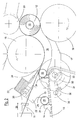
- Figure 1 shows the rewinding machine and the device of the invention appears in stand-by, whereby the introducer 34 does not act and the blade 24 is raised, far from the cores 15 and from the paper 11.
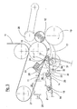
- the core 15 is in an exchange phase, the introducer 34 is adjacent to it and the cam portion 35 of the cam wheel 31 is about to come into contact with the feeler 30 to make the arms 22 oscillate.
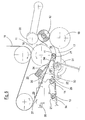
- the introducer 34 is in movement and acts on the core 15, the cam portion 25 moves the arms 22 and causes the blade 24 to descend and block the paper 11 which is torn in the closest point to the perforation after the core 15.
- figure 5 illustrates more clearly how the log 12 formed between the rolls leaves the same and the wound core 15 is brought to the winding phase. It is also evident that the introducer 34 returns to the low disengagement position and another core 15 is moved forwards.
- the device of the invention is extremely simple and the capturing strip of the paper is extremely short and reduced to the minimum.
Landscapes
- Life Sciences & Earth Sciences (AREA)
- Forests & Forestry (AREA)
- Engineering & Computer Science (AREA)
- Mechanical Engineering (AREA)
- Replacement Of Web Rolls (AREA)
Abstract
Description
- The present invention relates to a rapid tearing device of a strip in a rewinding machine.
- In the field of machines suitable for the formation of rolls or "logs" of paper destined for the preparation of toilet paper, blotting paper and/or similar products, rewinding machines are envisaged, which wind the continuous paper coming from a large paper roll, onto cores. For the production of paper rolls, in fact, there is a feeding of a continuous strip of paper material along a pre-defined route. It should be noted that the continuous strip, after starting its unwinding in a certain course, encounters a punching group whereby it is provided with transversal perforation lines to facilitate breakage and consequently the tearing of short sections of paper having a predetermined length.
- The continuous strip therefore contains a series of transversal perforated weakening lines, parallel to each other and spaced at regular intervals.
- The continuous strip thus treated, is introduced into the rewinding machine, where it is wound onto a cardboard supporting core, tubular in form, externally having a pre-determined portion of glue along a generatrix of the core.
- The rotation of the core by means of a group of winding rolls causes the winding of the continuous strip until the respective roll or "log" of wrapping paper has been formed. As already mentioned, at the beginning of the winding, a piece of the strip is joined to the core by means of glue positioned on the latter.
- At the end of the winding of a predetermined amount of continuous paper strip, the tail of the log must be separated thus contemporaneously creating the head of a new log to be formed.
- The separation operation of the continuous strip is effected, for example, by means of tearing which causes the breakage of the continuous strip along one of the perforated lines produced on the paper and mentioned above.
- This separation can be effected in various ways and using various devices. The tearing action of the continuous strip can be effected, for example, by varying the rotation rate of the winding rolls so as to create a section of strip sufficient for causing its breakage along a respective transversal perforated line.
- Alternatively, in
EP 1618057 , the tearing of the continuous strip is effected by the high-pressure blowing of a fluid against the perforated line in order to cause its breakage. - Comb- or buffer-elements are also envisaged, which intervene on the strip near a perforation line and block the paper on the upper winding cylinder in order to effect the above-mentioned separation.
- Even if the above systems and methods for the separation of the continuous strip of paper material allow the desired breakage of the paper to be effected along the transversal perforated line selected, these methods are either particularly complex or they generate folds on the paper and problems downstream during rewinding.
- The general objective of the present invention is to solve the above-mentioned drawbacks of the known art in a simple, economical and particularly functional way.
- Another objective of the invention is to provide device for the rapid tearing of a strip in a rewinding machine which does not cause folds on the paper which is being wound onto the core.
- Yet another objective of the invention is to provide a device for the rapid tearing of a strip in a rewinding machine which causes the least possible waste of paper being wound before the paper adheres to the glue carried by the core.
- A further objective of the present invention is to provide a device for the rapid tearing of a strip in a rewinding machine which does not use buffers or, in any case, does not exploit the combined action with the upper winding roll.
- In view of the above objectives, according to the present invention, a device has been conceived for the rapid tearing of a strip in a rewinding machine having the characteristics indicated in the enclosed claims.
- The structural and functional characteristics of the present invention and its advantages with respect to the known art will appear more evident from the following description referring to the enclosed drawings, which show, inter alia, a scheme of an embodiment of a rapid tearing device of a strip in a rewinding machine produced according to the same invention. In the drawings:
-
fig. 1 shows a schematic and synthetic view of the main parts of a rewinding machine which comprises a rapid tearing device of a strip, according to the present invention; -
figure 2 is an enlarged detail of what is shown infigure 1 , in a subsequent operative phase; -
figures 3 to 5 show, in similar views offigure 1 , subsequent operative phases of the rapid tearing device of a strip in a rewinding machine according to the invention. - With reference to
figure 1 , this substantially illustrates the core of a rewinding machine in which a rapid tearing device of a continuous strip of paper according to the invention, is positioned. - The rewinding machine at which a continuous strip of
paper 11 arrives, such as, for example, toilet paper, blotting paper and/or other types of paper materials, essentially comprises an area in which the rolls orlogs 12 of paper are prepared. - A
conveyor 13 equipped withpushers 14 for the advancing ofcores 15, made of cardboard for example, is positioned upstream of this area for the formation of the log. - The end of the
conveyor 13 faces achannel 16 defined by a series ofcradles 17 integral with the structure of the rewinder. - An
upper winding roll 18 is positioned above thechannel 16, orcradles 17, whereas alower winding roll 19 is situated almost at the end of thecradles 17. A third oscillatingroll 20 is positioned above thelower winding roll 19, cooperating with it and with the upper winding roll and acting as a press with a variation in the dimension of thelog 12 being formed between the three mentionedrolls - The
cores 15, carried by theconveyor 13 by means of thepushers 14, are previously provided with sections ofglue 21, situated in correspondence with the area where the finger on a watch indicates nine. According to the present invention, a device according to the present invention is situated in a similar arrangement of the rewinder. - A pair of
arms 22 are in fact envisaged, only one of which is shown, situated in opposite positions with respect to the ends of the rolls. The twoarms 22 carry across-piece 23, for example tubular, on which ablade 24 is positioned, arranged transversally with respect to the advancing of the paper, which has the same size as the width of the mentionedrolls - The
blade 24 can be moved by means of actuators, between a stand-by position and an engagement position on acore 15, when thiscore 15 is discharged by theconveyor 13 and introduced into thechannel 16 so as to block, between thecore 15 andblade 24, thepaper 11 which is being unwound and passing through this point. - The
arms 22 oscillate aroundcentral pins 25 and twospring cylinders 27 are connected to these at a first end, infurther pins 26, thespring cylinders 27 being hinged in turn at the other end of the arms by means ofpins 28 to the structure of the rewinder. - The
cylinders 27 act as elastic means and operate so that the arms are pulled back according to thearrow 29 offigure 1 , i.e. moved away from theupper roll 18 so that theblade 24 does not interfere with one of thecores 15 pushed forwards by thepushers 14 of theconveyor 13, to be sent inside thechannel 16. Furthermore, they normally keep thefeelers 30 in contact with acam wheel 31. - The device of the invention also envisages that the
arms 22 oscillate by means of a cam wheel - movable feeler coupling in synchronism with a discharge introducer 34 of acore 15 from theconveyor 13 towards thechannel 16. - More specifically, the cam wheel - movable feeler coupling envisages that a
feeler 30 be positioned at the end of the oscillatingarms 22, opposite to that where theblade 24 is situated. Thefeeler 30 is kept in contact with an outer surface of acam wheel 31 positioned on thesame axis 33 as atoothed wheel 32 which activates the movement of theconveyor 13. In this way the above-mentioned actuating means of theblade 24 are produced. - Furthermore, the
cam wheel 31, ortoothed wheel 32, carries at least one introducer 34 which discharges thecore 15 carried by thepushers 14 of theconveyor 13 and introduces or inserts it at the inlet ofchannel 16. - A
cam portion 35 radially protruding outwardly from thecam wheel 31, acts on thefeeler 30 of the twoarms 22 when acore 15 is introduced by theintroducer 34 at the inlet of thechannel 16. - In this way, the
arms 22 oscillate clockwise infigure 3 , according to thearrow 36, overcoming the force of thespring cylinders 27 and thecore 15 is pressed between theblade 24, thepusher 14 and the cradles 17 (figure 3 ). - In this way, the
paper 11 is also pressed between the walls in contact with each other, and stops. Thepaper 11 is torn in the transversalperforated line 37, closest to thecore 15, due to the strong deceleration it undergoes as a result of the pressure of thecore 15 on theblade 24 which has stopped in the maximum proximity position towards theconveyor 13. In this way, thelog 12, in formation, is freed and can be removed from its grip between therolls core 15 which is thus introduced into thechannel 16. -
Figure 4 shows how, by continuing the introduction of thecore 15 into thechannel 16 by means of thepusher 34, the lengths ofglue 21, i.e. the glue, are put in contact with thepaper 11 just before the head of the paper separated by the device of the invention. -
Figure 5 shows a subsequent step, wherein thecore 15, with the respective gluedpaper 11, is made to roll into thechannel 16 by the action of theupper roll 18, to be positioned between therolls log 12. - In the meantime, in an immediately subsequent step to that of the tearing shown in
figure 3 , the continuous rotation of thetoothed wheel 32, orcam wheel 31, causes disengagement between thecam portion 35 of thecam wheel 31 and feeler 30 of the twoarms 22, with backward oscillation of the same arms brought back by the cylinders 27 (figure 4 ). - The originality of this device consists in the fact that, as in previous devices, there is no specific device (a buffer, for example) which slows down the paper and tears it in the point closest to the perforation, acting on the upper winding roll. It is, in fact, the
same core 15 which, in collaboration with theblade 24 situated near thepaper 11, grips the paper and tears it. - The operative phases previously illustrated can be summarized by making reference to the figures.
-
Figure 1 shows the rewinding machine and the device of the invention appears in stand-by, whereby theintroducer 34 does not act and theblade 24 is raised, far from thecores 15 and from thepaper 11. - In
figure 2 , thecore 15 is in an exchange phase, theintroducer 34 is adjacent to it and thecam portion 35 of thecam wheel 31 is about to come into contact with thefeeler 30 to make thearms 22 oscillate. - In
figure 3 , theintroducer 34 is in movement and acts on thecore 15, thecam portion 25 moves thearms 22 and causes theblade 24 to descend and block thepaper 11 which is torn in the closest point to the perforation after thecore 15. - In
Figure 4 , thecore 15 enters thecradles 17 and is rotated by theupper roll 18. In this way, theglue 21 is put, with the core, in contact with thepaper 11 so as to form a new winding. - Finally,
figure 5 illustrates more clearly how thelog 12 formed between the rolls leaves the same and thewound core 15 is brought to the winding phase. It is also evident that the introducer 34 returns to the low disengagement position and anothercore 15 is moved forwards. - It can therefore be seen that the device of the invention is extremely simple and the capturing strip of the paper is extremely short and reduced to the minimum.
- The objective mentioned in the preamble of the description has therefore been achieved.
- The forms of the structure for the production of a device according to the invention, as also the materials and assembly modes, can obviously differ from those shown for purely illustrative and non-limiting purposes in the drawings.
- The protection scope of the present invention is therefore delimited by the enclosed claims.
Claims (6)
- A rapid tearing device of a strip in a rewinder for the winding of paper around a core (15) to produce a log (12), wherein said rewinder essentially comprises a formation area of the log (12) upstream of which there is a conveyor (13) with pushers (14) for moving cores (15) forward into a channel (16) defined by a series of cradles (17) integral with the structure of the rewinder, and by an upper winding roller (18) which is situated above the channel (16), wherein the upper winding roller (18) collaborates with a lower winding roller (19) positioned almost at the final end of the cradles (17), whereas a third oscillating roller (20) is situated above the lower winding roller (19) and acts as a press with the variation in the dimension of the log (12) being formed between the three mentioned rollers (18, 19 and 20), said device essentially consisting of a blade (24), having the dimension of the width of the rollers (18, 19, 20), which can be moved by actuators (31, 35; 30, 22, 25) between a rest position and an engagement position on a core (15) when the core (15) is unloaded from said conveyor (13) by means of an introducer (34) and introduced into the channel (16) thus blocking, between core (15) and blade (24), the paper (11) which is being unwound in order to tear it in the transversal perforation point after said contact (in 37).
- The device according to claim 1, characterized in that said blade (24) is positioned on an end of arms (22) hinged centrally (in 25) and made to oscillate by means of a cam wheel (31) - feeler (30) coupling which moves in synchronism with said discharge introducer (34) of a core from said conveyor (13) towards said channel (16).
- The device according to claim 2, characterized in that said arms (22) carry said blade (24) at a first end and a feeler (30) at the other end, kept in contact with a cam wheel (31) of said cam wheel (31) - feeler (30) coupling by elastic contrast means (27).
- The device according to claim 2, characterized in that said elastic contrast means are spring cylinders (27).
- The device according to claim 1, characterized in that said introducer (34) is arranged integral with a toothed wheel (32) which moves the conveyor (13) and is coaxial to a cam wheel (31) which forms part of a cam wheel (31) - feeler (30) coupling which moves in synchronism with said discharge introducer (34) of a core from said conveyor (13) towards said channel (16).
- The device according to one or more of claims 2 to 5, characterized in that said cam wheel (31) comprises a cam portion (35) protruding radially outwards.
Priority Applications (1)
| Application Number | Priority Date | Filing Date | Title |
|---|---|---|---|
| EP12172520.4A EP2676906B1 (en) | 2012-06-19 | 2012-06-19 | Rapid tearing device of a strip in a rewinding machine |
Applications Claiming Priority (1)
| Application Number | Priority Date | Filing Date | Title |
|---|---|---|---|
| EP12172520.4A EP2676906B1 (en) | 2012-06-19 | 2012-06-19 | Rapid tearing device of a strip in a rewinding machine |
Publications (2)
| Publication Number | Publication Date |
|---|---|
| EP2676906A1 true EP2676906A1 (en) | 2013-12-25 |
| EP2676906B1 EP2676906B1 (en) | 2017-08-23 |
Family
ID=46319002
Family Applications (1)
| Application Number | Title | Priority Date | Filing Date |
|---|---|---|---|
| EP12172520.4A Active EP2676906B1 (en) | 2012-06-19 | 2012-06-19 | Rapid tearing device of a strip in a rewinding machine |
Country Status (1)
| Country | Link |
|---|---|
| EP (1) | EP2676906B1 (en) |
Cited By (3)
| Publication number | Priority date | Publication date | Assignee | Title |
|---|---|---|---|---|
| US10427902B2 (en) | 2016-03-04 | 2019-10-01 | The Procter & Gamble Company | Enhanced introductory portion for a surface winder |
| US10427903B2 (en) | 2016-03-04 | 2019-10-01 | The Procter & Gamble Company | Leading edge device for a surface winder |
| US10442649B2 (en) | 2016-03-04 | 2019-10-15 | The Procter & Gamble Company | Surface winder for producing logs of convolutely wound web materials |
Citations (6)
| Publication number | Priority date | Publication date | Assignee | Title |
|---|---|---|---|---|
| EP1618057A2 (en) | 2003-04-28 | 2006-01-25 | Fabio Perini | Apparatus and method for causing paper webs to tear off within rewinding machines |
| WO2007083336A2 (en) * | 2006-01-18 | 2007-07-26 | Fabio Perini S.P.A. | Rewinding machine and winding method for the production of logs |
| WO2010004521A1 (en) * | 2008-07-10 | 2010-01-14 | Guglielmo Biagiotti | Apparatus, and method thereof, for processing a web material |
| EP2253568A2 (en) * | 2009-05-22 | 2010-11-24 | Chan Li Machinery Co., Ltd. | Winding device and method for tearing off web material by planetary-roller |
| US20110309185A1 (en) * | 2007-07-27 | 2011-12-22 | Chan Li Machinery Co., Ltd. | Method and structure for separating the web material in a winding machine |
| EP2422943A1 (en) * | 2010-08-27 | 2012-02-29 | Gambini International S.A. | Tearing device of a continuous ribbon of paper material to be supplied on rewinding machines, rewinding machine for the formation of logs of paper equipped with such a device and tearing method of a continuous ribbon of paper material on rewinding machines |
-
2012
- 2012-06-19 EP EP12172520.4A patent/EP2676906B1/en active Active
Patent Citations (6)
| Publication number | Priority date | Publication date | Assignee | Title |
|---|---|---|---|---|
| EP1618057A2 (en) | 2003-04-28 | 2006-01-25 | Fabio Perini | Apparatus and method for causing paper webs to tear off within rewinding machines |
| WO2007083336A2 (en) * | 2006-01-18 | 2007-07-26 | Fabio Perini S.P.A. | Rewinding machine and winding method for the production of logs |
| US20110309185A1 (en) * | 2007-07-27 | 2011-12-22 | Chan Li Machinery Co., Ltd. | Method and structure for separating the web material in a winding machine |
| WO2010004521A1 (en) * | 2008-07-10 | 2010-01-14 | Guglielmo Biagiotti | Apparatus, and method thereof, for processing a web material |
| EP2253568A2 (en) * | 2009-05-22 | 2010-11-24 | Chan Li Machinery Co., Ltd. | Winding device and method for tearing off web material by planetary-roller |
| EP2422943A1 (en) * | 2010-08-27 | 2012-02-29 | Gambini International S.A. | Tearing device of a continuous ribbon of paper material to be supplied on rewinding machines, rewinding machine for the formation of logs of paper equipped with such a device and tearing method of a continuous ribbon of paper material on rewinding machines |
Cited By (3)
| Publication number | Priority date | Publication date | Assignee | Title |
|---|---|---|---|---|
| US10427902B2 (en) | 2016-03-04 | 2019-10-01 | The Procter & Gamble Company | Enhanced introductory portion for a surface winder |
| US10427903B2 (en) | 2016-03-04 | 2019-10-01 | The Procter & Gamble Company | Leading edge device for a surface winder |
| US10442649B2 (en) | 2016-03-04 | 2019-10-15 | The Procter & Gamble Company | Surface winder for producing logs of convolutely wound web materials |
Also Published As
| Publication number | Publication date |
|---|---|
| EP2676906B1 (en) | 2017-08-23 |
Similar Documents
| Publication | Publication Date | Title |
|---|---|---|
| CA2902052C (en) | Rewinding machine and method for producing rolls of web material | |
| KR101760544B1 (en) | Rewinding machine and method for the production of rolls of web material | |
| US3770172A (en) | One-at-a-time alternate dispensing method | |
| EP1877332B1 (en) | Method and device for manufacturing rolls of web material with an outer wrapping | |
| EP1551740B1 (en) | Method for producing logs of web material and rewinding machine implementing said method | |
| ITMI20090103A1 (en) | IMPROVED REWINDING MACHINE AND RELATIVE METHOD FOR WINDING THE PAPER AROUND A SOUL FOR THE REALIZATION OF A PAPER ROLL | |
| CN1890167B (en) | Rewinding machine and method for the production of logs of web material and logs obtained | |
| ITFI20100245A1 (en) | "REWINDING MACHINE AND WINDING METHOD" | |
| US8979013B2 (en) | Rapid tearing device of a strip in a rewinding machine | |
| EP2676906B1 (en) | Rapid tearing device of a strip in a rewinding machine | |
| ITMI20082314A1 (en) | GROUP AND PAPER WINDING METHOD AROUND A SOUL TO CREATE A PAPER ROLL | |
| CA2528335C (en) | Systems producing a centre-feed roll with a protruding tapered feeding stem | |
| EP2731894B1 (en) | Method and apparatus for breaking a web using a cut-off assembly | |
| CN100562469C (en) | Method and device for producing strip reels | |
| EP4081472B1 (en) | Rewinding machine and method for the production of logs of paper material | |
| EP4081471B1 (en) | Rewinding machine and method for the production of logs of paper material | |
| ITMI20002399A1 (en) | PERIPHERAL REWINDING MACHINE AND METHOD FOR THE PRODUCTION OF LOGS OF SHEET MATERIALS | |
| EP3049356B1 (en) | Device and method for controlling the separation of sheets of paper webs in rewinding machines and a rewinding machine provided with such a device | |
| EP3502022B1 (en) | Rewinding machine and relative method for rewinding and forming a roll of paper | |
| WO2020254261A1 (en) | Method and machine for producing rolls of web material wound around tubular cores | |
| CA2794657A1 (en) | Systems producing a centre-feed roll with a protruding tapered feeding stem |
Legal Events
| Date | Code | Title | Description |
|---|---|---|---|
| PUAI | Public reference made under article 153(3) epc to a published international application that has entered the european phase |
Free format text: ORIGINAL CODE: 0009012 |
|
| AK | Designated contracting states |
Kind code of ref document: A1 Designated state(s): AL AT BE BG CH CY CZ DE DK EE ES FI FR GB GR HR HU IE IS IT LI LT LU LV MC MK MT NL NO PL PT RO RS SE SI SK SM TR |
|
| AX | Request for extension of the european patent |
Extension state: BA ME |
|
| 17P | Request for examination filed |
Effective date: 20140605 |
|
| RBV | Designated contracting states (corrected) |
Designated state(s): AL AT BE BG CH CY CZ DE DK EE ES FI FR GB GR HR HU IE IS IT LI LT LU LV MC MK MT NL NO PL PT RO RS SE SI SK SM TR |
|
| REG | Reference to a national code |
Ref country code: DE Ref legal event code: R079 Ref document number: 602012036195 Country of ref document: DE Free format text: PREVIOUS MAIN CLASS: B65H0019260000 Ipc: B65H0019220000 |
|
| RIC1 | Information provided on ipc code assigned before grant |
Ipc: B65H 19/28 20060101ALI20170317BHEP Ipc: B26D 1/34 20060101ALI20170317BHEP Ipc: B65H 19/22 20060101AFI20170317BHEP Ipc: B65H 19/26 20060101ALI20170317BHEP Ipc: B26F 3/00 20060101ALI20170317BHEP |
|
| GRAP | Despatch of communication of intention to grant a patent |
Free format text: ORIGINAL CODE: EPIDOSNIGR1 |
|
| INTG | Intention to grant announced |
Effective date: 20170508 |
|
| GRAS | Grant fee paid |
Free format text: ORIGINAL CODE: EPIDOSNIGR3 |
|
| GRAA | (expected) grant |
Free format text: ORIGINAL CODE: 0009210 |
|
| AK | Designated contracting states |
Kind code of ref document: B1 Designated state(s): AL AT BE BG CH CY CZ DE DK EE ES FI FR GB GR HR HU IE IS IT LI LT LU LV MC MK MT NL NO PL PT RO RS SE SI SK SM TR |
|
| REG | Reference to a national code |
Ref country code: GB Ref legal event code: FG4D |
|
| REG | Reference to a national code |
Ref country code: CH Ref legal event code: EP |
|
| REG | Reference to a national code |
Ref country code: AT Ref legal event code: REF Ref document number: 921091 Country of ref document: AT Kind code of ref document: T Effective date: 20170915 |
|
| REG | Reference to a national code |
Ref country code: IE Ref legal event code: FG4D |
|
| REG | Reference to a national code |
Ref country code: DE Ref legal event code: R096 Ref document number: 602012036195 Country of ref document: DE |
|
| REG | Reference to a national code |
Ref country code: NL Ref legal event code: MP Effective date: 20170823 |
|
| REG | Reference to a national code |
Ref country code: LT Ref legal event code: MG4D |
|
| REG | Reference to a national code |
Ref country code: AT Ref legal event code: MK05 Ref document number: 921091 Country of ref document: AT Kind code of ref document: T Effective date: 20170823 |
|
| PG25 | Lapsed in a contracting state [announced via postgrant information from national office to epo] |
Ref country code: AT Free format text: LAPSE BECAUSE OF FAILURE TO SUBMIT A TRANSLATION OF THE DESCRIPTION OR TO PAY THE FEE WITHIN THE PRESCRIBED TIME-LIMIT Effective date: 20170823 Ref country code: NO Free format text: LAPSE BECAUSE OF FAILURE TO SUBMIT A TRANSLATION OF THE DESCRIPTION OR TO PAY THE FEE WITHIN THE PRESCRIBED TIME-LIMIT Effective date: 20171123 Ref country code: HR Free format text: LAPSE BECAUSE OF FAILURE TO SUBMIT A TRANSLATION OF THE DESCRIPTION OR TO PAY THE FEE WITHIN THE PRESCRIBED TIME-LIMIT Effective date: 20170823 Ref country code: SE Free format text: LAPSE BECAUSE OF FAILURE TO SUBMIT A TRANSLATION OF THE DESCRIPTION OR TO PAY THE FEE WITHIN THE PRESCRIBED TIME-LIMIT Effective date: 20170823 Ref country code: FI Free format text: LAPSE BECAUSE OF FAILURE TO SUBMIT A TRANSLATION OF THE DESCRIPTION OR TO PAY THE FEE WITHIN THE PRESCRIBED TIME-LIMIT Effective date: 20170823 Ref country code: LT Free format text: LAPSE BECAUSE OF FAILURE TO SUBMIT A TRANSLATION OF THE DESCRIPTION OR TO PAY THE FEE WITHIN THE PRESCRIBED TIME-LIMIT Effective date: 20170823 Ref country code: NL Free format text: LAPSE BECAUSE OF FAILURE TO SUBMIT A TRANSLATION OF THE DESCRIPTION OR TO PAY THE FEE WITHIN THE PRESCRIBED TIME-LIMIT Effective date: 20170823 |
|
| PG25 | Lapsed in a contracting state [announced via postgrant information from national office to epo] |
Ref country code: RS Free format text: LAPSE BECAUSE OF FAILURE TO SUBMIT A TRANSLATION OF THE DESCRIPTION OR TO PAY THE FEE WITHIN THE PRESCRIBED TIME-LIMIT Effective date: 20170823 Ref country code: GR Free format text: LAPSE BECAUSE OF FAILURE TO SUBMIT A TRANSLATION OF THE DESCRIPTION OR TO PAY THE FEE WITHIN THE PRESCRIBED TIME-LIMIT Effective date: 20171124 Ref country code: LV Free format text: LAPSE BECAUSE OF FAILURE TO SUBMIT A TRANSLATION OF THE DESCRIPTION OR TO PAY THE FEE WITHIN THE PRESCRIBED TIME-LIMIT Effective date: 20170823 Ref country code: BG Free format text: LAPSE BECAUSE OF FAILURE TO SUBMIT A TRANSLATION OF THE DESCRIPTION OR TO PAY THE FEE WITHIN THE PRESCRIBED TIME-LIMIT Effective date: 20171123 Ref country code: IS Free format text: LAPSE BECAUSE OF FAILURE TO SUBMIT A TRANSLATION OF THE DESCRIPTION OR TO PAY THE FEE WITHIN THE PRESCRIBED TIME-LIMIT Effective date: 20171223 Ref country code: PL Free format text: LAPSE BECAUSE OF FAILURE TO SUBMIT A TRANSLATION OF THE DESCRIPTION OR TO PAY THE FEE WITHIN THE PRESCRIBED TIME-LIMIT Effective date: 20170823 Ref country code: ES Free format text: LAPSE BECAUSE OF FAILURE TO SUBMIT A TRANSLATION OF THE DESCRIPTION OR TO PAY THE FEE WITHIN THE PRESCRIBED TIME-LIMIT Effective date: 20170823 |
|
| PG25 | Lapsed in a contracting state [announced via postgrant information from national office to epo] |
Ref country code: CZ Free format text: LAPSE BECAUSE OF FAILURE TO SUBMIT A TRANSLATION OF THE DESCRIPTION OR TO PAY THE FEE WITHIN THE PRESCRIBED TIME-LIMIT Effective date: 20170823 Ref country code: RO Free format text: LAPSE BECAUSE OF FAILURE TO SUBMIT A TRANSLATION OF THE DESCRIPTION OR TO PAY THE FEE WITHIN THE PRESCRIBED TIME-LIMIT Effective date: 20170823 Ref country code: DK Free format text: LAPSE BECAUSE OF FAILURE TO SUBMIT A TRANSLATION OF THE DESCRIPTION OR TO PAY THE FEE WITHIN THE PRESCRIBED TIME-LIMIT Effective date: 20170823 |
|
| REG | Reference to a national code |
Ref country code: DE Ref legal event code: R097 Ref document number: 602012036195 Country of ref document: DE |
|
| PG25 | Lapsed in a contracting state [announced via postgrant information from national office to epo] |
Ref country code: SK Free format text: LAPSE BECAUSE OF FAILURE TO SUBMIT A TRANSLATION OF THE DESCRIPTION OR TO PAY THE FEE WITHIN THE PRESCRIBED TIME-LIMIT Effective date: 20170823 Ref country code: SM Free format text: LAPSE BECAUSE OF FAILURE TO SUBMIT A TRANSLATION OF THE DESCRIPTION OR TO PAY THE FEE WITHIN THE PRESCRIBED TIME-LIMIT Effective date: 20170823 Ref country code: EE Free format text: LAPSE BECAUSE OF FAILURE TO SUBMIT A TRANSLATION OF THE DESCRIPTION OR TO PAY THE FEE WITHIN THE PRESCRIBED TIME-LIMIT Effective date: 20170823 |
|
| PLBE | No opposition filed within time limit |
Free format text: ORIGINAL CODE: 0009261 |
|
| STAA | Information on the status of an ep patent application or granted ep patent |
Free format text: STATUS: NO OPPOSITION FILED WITHIN TIME LIMIT |
|
| 26N | No opposition filed |
Effective date: 20180524 |
|
| PG25 | Lapsed in a contracting state [announced via postgrant information from national office to epo] |
Ref country code: SI Free format text: LAPSE BECAUSE OF FAILURE TO SUBMIT A TRANSLATION OF THE DESCRIPTION OR TO PAY THE FEE WITHIN THE PRESCRIBED TIME-LIMIT Effective date: 20170823 |
|
| REG | Reference to a national code |
Ref country code: DE Ref legal event code: R119 Ref document number: 602012036195 Country of ref document: DE |
|
| REG | Reference to a national code |
Ref country code: CH Ref legal event code: PL |
|
| GBPC | Gb: european patent ceased through non-payment of renewal fee |
Effective date: 20180619 |
|
| REG | Reference to a national code |
Ref country code: BE Ref legal event code: MM Effective date: 20180630 |
|
| REG | Reference to a national code |
Ref country code: IE Ref legal event code: MM4A |
|
| PG25 | Lapsed in a contracting state [announced via postgrant information from national office to epo] |
Ref country code: MC Free format text: LAPSE BECAUSE OF FAILURE TO SUBMIT A TRANSLATION OF THE DESCRIPTION OR TO PAY THE FEE WITHIN THE PRESCRIBED TIME-LIMIT Effective date: 20170823 Ref country code: LU Free format text: LAPSE BECAUSE OF NON-PAYMENT OF DUE FEES Effective date: 20180619 |
|
| PG25 | Lapsed in a contracting state [announced via postgrant information from national office to epo] |
Ref country code: LI Free format text: LAPSE BECAUSE OF NON-PAYMENT OF DUE FEES Effective date: 20180630 Ref country code: IE Free format text: LAPSE BECAUSE OF NON-PAYMENT OF DUE FEES Effective date: 20180619 Ref country code: DE Free format text: LAPSE BECAUSE OF NON-PAYMENT OF DUE FEES Effective date: 20190101 Ref country code: FR Free format text: LAPSE BECAUSE OF NON-PAYMENT OF DUE FEES Effective date: 20180630 Ref country code: GB Free format text: LAPSE BECAUSE OF NON-PAYMENT OF DUE FEES Effective date: 20180619 Ref country code: CH Free format text: LAPSE BECAUSE OF NON-PAYMENT OF DUE FEES Effective date: 20180630 |
|
| PG25 | Lapsed in a contracting state [announced via postgrant information from national office to epo] |
Ref country code: BE Free format text: LAPSE BECAUSE OF NON-PAYMENT OF DUE FEES Effective date: 20180630 |
|
| PG25 | Lapsed in a contracting state [announced via postgrant information from national office to epo] |
Ref country code: MT Free format text: LAPSE BECAUSE OF NON-PAYMENT OF DUE FEES Effective date: 20180619 |
|
| PG25 | Lapsed in a contracting state [announced via postgrant information from national office to epo] |
Ref country code: TR Free format text: LAPSE BECAUSE OF FAILURE TO SUBMIT A TRANSLATION OF THE DESCRIPTION OR TO PAY THE FEE WITHIN THE PRESCRIBED TIME-LIMIT Effective date: 20170823 |
|
| PG25 | Lapsed in a contracting state [announced via postgrant information from national office to epo] |
Ref country code: HU Free format text: LAPSE BECAUSE OF FAILURE TO SUBMIT A TRANSLATION OF THE DESCRIPTION OR TO PAY THE FEE WITHIN THE PRESCRIBED TIME-LIMIT; INVALID AB INITIO Effective date: 20120619 Ref country code: PT Free format text: LAPSE BECAUSE OF FAILURE TO SUBMIT A TRANSLATION OF THE DESCRIPTION OR TO PAY THE FEE WITHIN THE PRESCRIBED TIME-LIMIT Effective date: 20170823 |
|
| PG25 | Lapsed in a contracting state [announced via postgrant information from national office to epo] |
Ref country code: MK Free format text: LAPSE BECAUSE OF NON-PAYMENT OF DUE FEES Effective date: 20170823 Ref country code: CY Free format text: LAPSE BECAUSE OF FAILURE TO SUBMIT A TRANSLATION OF THE DESCRIPTION OR TO PAY THE FEE WITHIN THE PRESCRIBED TIME-LIMIT Effective date: 20170823 |
|
| PG25 | Lapsed in a contracting state [announced via postgrant information from national office to epo] |
Ref country code: AL Free format text: LAPSE BECAUSE OF FAILURE TO SUBMIT A TRANSLATION OF THE DESCRIPTION OR TO PAY THE FEE WITHIN THE PRESCRIBED TIME-LIMIT Effective date: 20170823 |
|
| P01 | Opt-out of the competence of the unified patent court (upc) registered |
Effective date: 20230610 |
|
| PGFP | Annual fee paid to national office [announced via postgrant information from national office to epo] |
Ref country code: IT Payment date: 20250623 Year of fee payment: 14 |