EP2676882A2 - DC power architecture for remote APU start - Google Patents
DC power architecture for remote APU start Download PDFInfo
- Publication number
- EP2676882A2 EP2676882A2 EP20130171202 EP13171202A EP2676882A2 EP 2676882 A2 EP2676882 A2 EP 2676882A2 EP 20130171202 EP20130171202 EP 20130171202 EP 13171202 A EP13171202 A EP 13171202A EP 2676882 A2 EP2676882 A2 EP 2676882A2
- Authority
- EP
- European Patent Office
- Prior art keywords
- auxiliary power
- power unit
- node
- response
- activation
- Prior art date
- Legal status (The legal status is an assumption and is not a legal conclusion. Google has not performed a legal analysis and makes no representation as to the accuracy of the status listed.)
- Granted
Links
Images


Classifications
-
- H—ELECTRICITY
- H02—GENERATION; CONVERSION OR DISTRIBUTION OF ELECTRIC POWER
- H02J—ELECTRIC POWER NETWORKS; CIRCUIT ARRANGEMENTS OR SYSTEMS FOR SUPPLYING OR DISTRIBUTING ELECTRIC POWER; SYSTEMS FOR STORING ELECTRIC ENERGY
- H02J9/00—Circuit arrangements for emergency or stand-by power supply, e.g. for emergency lighting
- H02J9/04—Circuit arrangements for emergency or stand-by power supply, e.g. for emergency lighting in which the distribution system is disconnected from the normal source and connected to a standby source
- H02J9/06—Circuit arrangements for emergency or stand-by power supply, e.g. for emergency lighting in which the distribution system is disconnected from the normal source and connected to a standby source with automatic change-over, e.g. UPS systems
-
- B—PERFORMING OPERATIONS; TRANSPORTING
- B64—AIRCRAFT; AVIATION; COSMONAUTICS
- B64D—EQUIPMENT FOR FITTING IN OR TO AIRCRAFT; FLIGHT SUITS; PARACHUTES; ARRANGEMENT OR MOUNTING OF POWER PLANTS OR PROPULSION TRANSMISSIONS IN AIRCRAFT
- B64D41/00—Power installations for auxiliary purposes
-
- F—MECHANICAL ENGINEERING; LIGHTING; HEATING; WEAPONS; BLASTING
- F02—COMBUSTION ENGINES; HOT-GAS OR COMBUSTION-PRODUCT ENGINE PLANTS
- F02N—STARTING OF COMBUSTION ENGINES; STARTING AIDS FOR SUCH ENGINES, NOT OTHERWISE PROVIDED FOR
- F02N11/00—Starting of engines by means of electric motors
- F02N11/08—Circuits specially adapted for starting of engines
- F02N11/0803—Circuits specially adapted for starting of engines characterised by means for initiating engine start or stop
- F02N11/0807—Remote means
-
- H—ELECTRICITY
- H02—GENERATION; CONVERSION OR DISTRIBUTION OF ELECTRIC POWER
- H02J—ELECTRIC POWER NETWORKS; CIRCUIT ARRANGEMENTS OR SYSTEMS FOR SUPPLYING OR DISTRIBUTING ELECTRIC POWER; SYSTEMS FOR STORING ELECTRIC ENERGY
- H02J9/00—Circuit arrangements for emergency or stand-by power supply, e.g. for emergency lighting
- H02J9/04—Circuit arrangements for emergency or stand-by power supply, e.g. for emergency lighting in which the distribution system is disconnected from the normal source and connected to a standby source
- H02J9/06—Circuit arrangements for emergency or stand-by power supply, e.g. for emergency lighting in which the distribution system is disconnected from the normal source and connected to a standby source with automatic change-over, e.g. UPS systems
- H02J9/08—Circuit arrangements for emergency or stand-by power supply, e.g. for emergency lighting in which the distribution system is disconnected from the normal source and connected to a standby source with automatic change-over, e.g. UPS systems requiring starting of a prime-mover
-
- B—PERFORMING OPERATIONS; TRANSPORTING
- B64—AIRCRAFT; AVIATION; COSMONAUTICS
- B64D—EQUIPMENT FOR FITTING IN OR TO AIRCRAFT; FLIGHT SUITS; PARACHUTES; ARRANGEMENT OR MOUNTING OF POWER PLANTS OR PROPULSION TRANSMISSIONS IN AIRCRAFT
- B64D2221/00—Electric power distribution systems onboard aircraft
-
- F—MECHANICAL ENGINEERING; LIGHTING; HEATING; WEAPONS; BLASTING
- F05—INDEXING SCHEMES RELATING TO ENGINES OR PUMPS IN VARIOUS SUBCLASSES OF CLASSES F01-F04
- F05D—INDEXING SCHEME FOR ASPECTS RELATING TO NON-POSITIVE-DISPLACEMENT MACHINES OR ENGINES, GAS-TURBINES OR JET-PROPULSION PLANTS
- F05D2220/00—Application
- F05D2220/50—Application for auxiliary power units (APU's)
-
- F—MECHANICAL ENGINEERING; LIGHTING; HEATING; WEAPONS; BLASTING
- F05—INDEXING SCHEMES RELATING TO ENGINES OR PUMPS IN VARIOUS SUBCLASSES OF CLASSES F01-F04
- F05D—INDEXING SCHEME FOR ASPECTS RELATING TO NON-POSITIVE-DISPLACEMENT MACHINES OR ENGINES, GAS-TURBINES OR JET-PROPULSION PLANTS
- F05D2260/00—Function
- F05D2260/85—Starting
Definitions
- Embodiments of the present disclosure relate generally to circuits. More particularly, embodiments of the present disclosure relate to engine starting circuits.
- Auxiliary power units (APU)s are devices on vehicles such as aircraft that provide an auxiliary source of electrical power in addition to or in absence of ground power (e.g., when an aircraft is at a gate or parked) or main engine generators (e.g., during taxi or in flight).
- APUs are found on commercial aircraft, and larger land and water vehicles such as tanks, trucks, and ships.
- An aircraft APU for running aircraft electrical systems may generally produce a 28V DC current or a 400 Hz AC current at a voltage of 115V.
- a circuit and methods for remote auxiliary power unit (APU) startup are presented.
- a first node is coupled to a ground by action of a momentary switch to initiate an activation, and the first node is coupled to the ground by action of a latching relay in response to the activation.
- An auxiliary power unit is coupled to a hot battery by action of a bi-polar relay in response to the activation.
- an APU can be started remotely via an exterior control such as a remote start switch near a crew entry door of a cold and dark airplane.
- the APU start control circuits, APU fire protection circuits and related fuel circuits are powered by a hot battery bus to start the APU when the external remote start switch is momentarily pressed on.
- the power source of related circuits will be switched back to a main battery bus when the flight crew/operator turns on the main battery switch or bring AC power online.
- a remote auxiliary power unit startup circuit comprises a momentary switch, a latching relay, a bi-polar relay, and an unlatching relay.
- the momentary switch couples a first node to a ground to initiate an activation.
- the latching relay couples the first node to the ground in response to the activation, and decouples the first node from the ground in response to a deactivation of a second node.
- the bi-polar relay couples an auxiliary power unit to a hot battery in response to the activation, and to a main power bus in response to the deactivation.
- the unlatching relay couples the second node to the hot battery, and initiates the deactivation by decoupling the second node from the hot battery in response to the auxiliary power unit starting.
- a method for remote auxiliary power unit startup couples a first node to a ground by action of a momentary switch to initiate an activation.
- the method further couples the first node to the ground by action of a latching relay in response to the activation, and couples an auxiliary power unit to a hot battery by action of a bi-polar relay in response to the activation.
- a method for providing a remote auxiliary power unit startup circuit provides a momentary switch operable to couple a first node to a ground to initiate an activation.
- the method further provides a latching relay that couples the first node to the ground in response to the activation, and decouples the first node from the ground in response to a deactivation of a second node.
- the method further provides a bi-polar relay that couples an auxiliary power unit to a hot battery in response to the activation, and to a main power bus in response to the deactivation.
- the method further provides an unlatching relay that couples the second node to the hot battery, and that initiates the deactivation of the second node by decoupling the second node from the hot battery in response to the auxiliary power unit starting.
- Embodiments of the disclosure may be described herein in terms of functional and/or logical block components and various processing steps. It should be appreciated that such block components may be realized by any number of hardware, software, and/or firmware components configured to perform the specified functions. For the sake of brevity, conventional techniques and components related to electronic circuits, electronic devices, auxiliary power units, and other functional aspects of systems described herein (and the individual operating components of the systems) may not be described in detail herein. In addition, those skilled in the art will appreciate that embodiments of the present disclosure may be practiced in conjunction with a variety of hardware and software, and that the embodiments described herein are merely example embodiments of the disclosure.
- Embodiments of the disclosure are described herein in the context of a non-limiting application, namely, an aircraft auxiliary power unit starting circuit. Embodiments of the disclosure, however, are not limited to such aircraft auxiliary power unit starting circuit applications, and the techniques described herein may also be utilized in other applications. For example but without limitation, embodiments may be applicable to train auxiliary power units, ship auxiliary power units, generators, or other engine starting application.
- An auxiliary power unit can be started remotely via an exterior control such as a remote start switch near a crew entry door of a cold & dark airplane.
- An APU start control circuit and/or other APU controller, APU fire protection circuits and related fuel circuits are powered by a hot battery bus to start the APU when the external remote start switch is momentarily pressed on.
- the power source of related circuits will be switched back to a main battery bus when flight crew/operator turns on a main battery switch or bring AC power online.
- embodiments of the disclosure may be described in the context of an exemplary aircraft manufacturing and service method 100 (method 100) as shown in Figure 1 and an aircraft 200 as shown in Figure 2 .
- the method 100 may comprise specification and design 104 of the aircraft 200, and material procurement 106.
- component and subassembly manufacturing 108 (process 108) and system integration 110 of the aircraft 200 takes place.
- the aircraft 200 may go through certification and delivery 112 in order to be placed in service 114.
- routine maintenance and service 116 which may also comprise modification, reconfiguration, refurbishment, and so on).
- a system integrator may comprise, for example but without limitation, any number of aircraft manufacturers and major-system subcontractors
- a third party may comprise, for example but without limitation, any number of vendors, subcontractors, and suppliers
- an operator may comprise, for example but without limitation, an airline, leasing company, military entity, service organization; and the like.
- the aircraft 200 produced by the method 100 may comprise an airframe 218 with a plurality of systems 220 and an interior 222.
- high-level systems of the systems 220 comprise one or more of a propulsion system 224, an electrical system 226, a hydraulic system 228, an environmental system 230, and a remote auxiliary power unit startup circuit 232. Any number of other systems may also be included.
- an aerospace example is shown, the embodiments of the disclosure may be applied to other industries.
- Apparatus and methods embodied herein may be employed during any one or more of the stages of the method 100.
- components or subassemblies corresponding to production of the process 108 may be fabricated or manufactured in a manner similar to components or subassemblies produced while the aircraft 200 is in service.
- one or more apparatus embodiments, method embodiments, or a combination thereof may be utilized during production stages of the process 108 and the system integration 110, for example, by substantially expediting assembly of or reducing the cost of an aircraft 200.
- one or more of apparatus embodiments, method embodiments, or a combination thereof may be utilized while the aircraft 200 is in service, for example and without limitation, to maintenance and service 116.
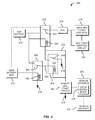
- FIG. 3 is an illustration of an exemplary remote auxiliary power unit startup circuit 300 according to an embodiment of the disclosure.
- the circuit 300 may comprise a momentary switch 302, a latching relay 304, a bi-polar relay 306, an unlatching relay 308, a hot battery 310, a main battery bus 312, an auxiliary power unit (APU) 314, and an APU start control circuit 324.
- APU auxiliary power unit
- the momentary switch 302 (remote APU start switch 302) is configured to couple a first node 320 to a ground 318 to initiate an activation.
- the momentary switch 302 closes to couple the first node 320 to the ground 318, and re-opens (releases) in a short period of time removing the coupling of the first node 320 to the ground 318 through the momentary switch 302.
- the momentary switch 302 closes when a button is pressed, and re-opens when the button is released (e.g., about 1-2 seconds).
- the momentary switch 302 may be operated by, for example but without limitation, a remote operation, a local operation, a wireless operation, an infrared operation, a pressed button, manual operation, or other type of operation.
- the momentary switch 302 may comprise, for example but without limitation, a momentary contact switch, a momentary single pole single throw switch, a bounce switch, or other switch.
- the activation may comprise activation of the bi-polar relay 306 and the latching relay 304. Coupling the first node 320 to the ground 318 initiates starting the APU 314 by activating the bi-polar relay 306 and the latching relay 304.
- the momentary switch 302 may activate the bi-polar relay 306 by, for example but without limitation, coupling a coil 332 of the bi-polar relay 306 to the ground 318. Thereby, a current flows from the hot battery 310 through the coil 332 to the ground 318 causing the bi-polar relay 306 to couple the APU 314 to the hot battery 310 (e.g., via a bus 316). Coupling the APU 314 to the hot battery 310 starts the APU 314.
- the momentary switch 302 may activate the latching relay 304 by, for example but without limitation, coupling a coil 334 of the latching relay 304 to the ground 318. Thereby, a current flows from the hot battery 310 through the coil 334 to the ground 318 causing the latching relay 304 to couple the coil 332 of the bi-polar relay 306 to the ground 318. Thereby, the coil 332 of the bi-polar relay 306 can remain coupled to the ground 318 after the momentary switch 302 re-opens and until the latching relay 304 is deactivated, which decouples the coil 332 of the bi-polar relay 306 from the ground 318.
- the latching relay 304 is configured to couple the first node 320 to the ground 318 in response to the activation.
- the latching relay 304 is further configured to decouple the first node 320 from the ground 318 in response to a deactivation of a second node 322.
- the latching relay 304 may comprise a single pole single throw switch 340 (shown in an open position) controlled by the coil 334, or other switch configuration.
- the latching relay 304 is activated when a current flows through the coil 334.
- the single pole single throw switch 340 couples the first node 320 and the coil 332 of the bi-polar relay 306 to the ground 318. Thereby, the bi-polar relay 306 is activated or remains activated.
- the latching relay 304 is deactivated when the current does not flow through the coil 334, e.g., when the second node 322 is deactivated by decoupling from the hot battery 310.
- the single pole single throw switch 340 decouples the first node 320 and the coil 332 of the bi-polar relay 306 from the ground 318. Thereby, the bi-polar relay 306 is deactivated.
- the bi-polar relay 306 is configured to couple the APU 314 and the APU start control circuit 324 to the hot battery 310 in response to the activation.
- the bi-polar relay 306 is further configured to couple the APU 314 to the main battery bus 312 in response to the deactivation.
- the bi-polar relay 306 may comprise a single pole double throw switch 342 (shown in an open position) controlled by the coil 332, or other switch configuration.
- the bi-polar relay 306 is activated when a current flows through the coil 332. When the current flows from the hot battery 310 through the coil 332 to the ground 318, the single pole double throw switch 342 couples the APU 314 and the APU start control circuit 324 to the hot battery 310.
- the bi-polar relay 306 is deactivated when the current does not flow through the coil 332, e.g., when the latching relay 304 is deactivated decoupling the coil 332 from the ground 318.
- the single pole double throw switch 342 couples the APU 314 and the APU start control circuit 324 to the main battery bus 312.
- the unlatching relay 308 is configured to couple the second node 322 to the hot battery 310.
- the unlatching relay 308 is further configured to initiate the deactivation of the second node 322 by decoupling the second node 322 from the hot battery 310 in response to the APU 314 starting.
- the unlatching relay 308 may comprise a single pole double throw switch 344 (shown in an open position) controlled by a coil 336, or other switch configuration.
- the single pole double throw switch 344 decouples the hot battery 310 from the second node 322 and the coil 334 of the latching relay 304.
- the coil 334 of the latching relay 304 is thereby deactivated (unpowered) and the single pole single throw switch 340 opens.
- the single pole double throw switch 344 couples the hot battery 310 to the second node 322 and the coil 334 of the latching relay 304.
- the coil 334 of the latching relay 304 is under control of the momentary switch 302 which controls a path to the ground 318 for a current to flow from the hot battery 310 through the coil 334.
- the hot battery 310 may comprise, for example but without limitation, a nickel metal hydride battery, a lithium battery, a lithium ion battery, or other battery.
- the hot battery 310 may comprise a battery comprising electrical power or charged with electrical power.
- the main battery bus 312 may comprise, for example but without limitation, a main aircraft electrical bus, an auxiliary electrical bus, a train power bus, or other power bus.
- the main battery bus 312 may be coupled to the APU 314 and energized with electrical energy when the APU 314 has been started (e.g., is operating).
- the auxiliary power unit (APU) 314 may comprise, for example but without limitation, a diesel engine, a fuel cell, or other engine.
- the APU 314 may also comprise the APU start control circuit 324.
- the auxiliary power unit (APU) 314 is operable to start when coupled to the hot battery 310.
- the APU start control circuit 324 is operable to initiate and control a start sequence of the APU 314.
- the APU start control circuit 324 may comprise, for example but without limitation, an APU controller, an APU fire protection circuit, fuel control circuits, an APU electronic control unit, or other APU related circuits.
- FIG. 4 is an illustration of an exemplary flowchart showing a process 400 for remote auxiliary power unit startup according to an embodiment of the disclosure.
- the various tasks performed in connection with process 500 may be performed mechanically, by software, hardware, firmware, computer-readable software, computer readable storage medium, or any combination thereof.
- process 400 may include any number of additional or alternative tasks, the tasks shown in Figure 4 need not be performed in the illustrated order, and the process 400 may be incorporated into a more comprehensive procedure or process having additional functionality not described in detail herein.
- process 400 may refer to elements mentioned above in connection with Figure 3 .
- portions of the process 400 may be performed by different elements of the circuit 300 such as: the momentary switch 302, the latching relay 304, the bi-polar relay 306, the unlatching relay 308, the hot battery 310, the main battery bus 312, etc.
- process 400 may include any number of additional or alternative tasks, the tasks shown in Figure 4 need not be performed in the illustrated order, and the process 400 may be incorporated into a more comprehensive procedure or process having additional functionality not described in detail herein.
- Process 400 may begin by coupling a first node such as the first node 320 to a ground such as the ground 318 by action of a momentary switch such as the momentary switch 302 to initiate an activation (task 402).
- Process 400 may continue by coupling the first node 320 to the ground 318 by action of a latching relay such as the latching relay 304 in response to the activation (task 404).
- a latching relay such as the latching relay 304
- Process 400 may continue by coupling an auxiliary power unit such as the APU 314 to a hot battery such as the hot battery 310 by action of a bi-polar relay such as the bi-polar relay 306 in response to the activation (task 406).
- the APU 314 comprises the APU start control circuit 324 that is also coupled to the hot battery 310 by the action of the bi-polar relay 306.
- Process 400 may continue by initiating a deactivation by decoupling a second node such as the second node 322 from the hot battery 310 by action of an unlatching relay such as the unlatching relay 308 in response to the auxiliary power unit 314 starting (task 408).
- Process 400 may continue by decoupling the first node 320 from the ground 318 by action of the latching relay 304 in response to the deactivation (task 410).
- Process 400 may continue by coupling the auxiliary power unit 314 to a main power bus such as the main battery bus 312 by action of the bi-polar relay 306 in response to the deactivation (task 412).
- Process 400 may continue by coupling the second node 322 to the hot battery 310 by action of the unlatching relay 308 (task 414).
- Process 400 may continue by activating the momentary switch 302 by one of: remote activation, and local activation (task 416).
- the momentary switch may be located on an exterior 326 of a vehicle 330.
- the momentary switch may be located on near a crew entry door 328 of the vehicle 330, wherein the vehicle 330 comprises an aircraft 330.
- FIG. 5 is an illustration of an exemplary flowchart showing a process 500 for providing a remote auxiliary power unit startup circuit according to an embodiment of the disclosure.
- the various tasks performed in connection with process 500 may be performed mechanically, by software, hardware, firmware, computer-readable software, computer readable storage medium, or any combination thereof. It should be appreciated that process 500 may include any number of additional or alternative tasks, the tasks shown in Figure 5 need not be performed in the illustrated order, and the process 500 may be incorporated into a more comprehensive procedure or process having additional functionality not described in detail herein.
- process 500 may refer to elements mentioned above in connection with Figure 3 .
- portions of the process 500 may be performed by different elements of the circuit 300 such as: the momentary switch 302, the latching relay 304, the bi-polar relay 306, the unlatching relay 308, the hot battery 310, the main battery bus 312, etc.
- process 500 may include any number of additional or alternative tasks, the tasks shown in Figure 5 need not be performed in the illustrated order, and the process 500 may be incorporated into a more comprehensive procedure or process having additional functionality not described in detail herein.
- Process 500 may begin by providing a momentary switch such as the momentary switch 302 operable to couple a first node such as the first node 320 to a ground such as the ground 318 to initiate an activation (task 502).
- the momentary switch 302 may be located, for example but without limitation, on an exterior of a vehicle.
- the momentary switch 302 may be located on the exterior 326 near the crew entry door 328 of the aircraft 330.
- the momentary switch may be activated remotely or locally by an operator.
- Process 500 may continue by providing a latching relay such as the latching relay 304 operable to couple the first node 320 to the ground 318 in response to the activation, and decouple the first node 320 from the ground 318 in response to a deactivation of a second node such as the second node 322 (task 504).
- a latching relay such as the latching relay 304 operable to couple the first node 320 to the ground 318 in response to the activation, and decouple the first node 320 from the ground 318 in response to a deactivation of a second node such as the second node 322 (task 504).
- Process 500 may continue by providing a bi-polar relay such as the bi-polar relay 306 operable to couple an auxiliary power unit such as the APU 314 to a hot battery such as the hot battery 310 in response to the activation, and a main power bus such as the main battery bus 312 in response to the deactivation of the second node 322 (task 506).
- a bi-polar relay such as the bi-polar relay 306 operable to couple an auxiliary power unit such as the APU 314 to a hot battery such as the hot battery 310 in response to the activation, and a main power bus such as the main battery bus 312 in response to the deactivation of the second node 322 (task 506).
- Process 500 may continue by providing an unlatching relay such as the unlatching relay 308 operable to couple the second node 322 to the hot battery 310, and initiate the deactivation of the second node 322 by decoupling the second node 322 from the hot battery 310 in response to the auxiliary power unit 314 starting (task 508).
- an unlatching relay such as the unlatching relay 308 operable to couple the second node 322 to the hot battery 310, and initiate the deactivation of the second node 322 by decoupling the second node 322 from the hot battery 310 in response to the auxiliary power unit 314 starting (task 508).
- Process 500 may continue by providing the momentary switch 302 on an exterior such as the exterior 326 of a vehicle such as the vehicle 330 (task 510).
- Process 500 may continue by providing the momentary switch 302 near a crew entry door such as the crew entry door 328 of the vehicle 330, wherein the vehicle 330 comprises an aircraft such as the aircraft 330 (task 512).
- an APU can be started remotely via an exterior control such as a momentary switch near a crew entry door of a cold & dark airplane.
- a remote auxiliary power unit startup circuit including: a momentary switch 302 operable to couple a first node 320 to a ground 318 to initiate an activation, a latching relay 304 operable to: couple the first node 320 to the ground 318 in response to the activation, and decouple the first node 320 from the ground 318 in response to a deactivation of a second node 322, a bi-polar relay 306 operable to couple an auxiliary power unit 314 to: a hot battery 310 in response to the activation, and a main power bus 312 in response to the deactivation, and an unlatching relay 308 operable to: couple the second node 322 to the hot battery 310, and initiate the deactivation by decoupling the second node 322 from the hot battery 310 in response to the auxiliary power unit 314 starting.
- the remote auxiliary power unit startup circuit includes wherein coupling the hot battery 310 to the auxiliary power unit 314 starts the auxiliary power unit 314.
- the remote auxiliary power unit startup circuit includes wherein the momentary switch 302 is located on an exterior of a vehicle.
- the remote auxiliary power unit startup circuit includes wherein the vehicle comprises an aircraft and the momentary switch 302 is located near a crew entry door of the aircraft.
- the remote auxiliary power unit startup circuit includes wherein the momentary switch 302 is activated by one of: remote activation, and local activation.
- the remote auxiliary power unit startup circuit includes wherein the auxiliary power unit comprises an APU start control circuit 324.
- a method for remote auxiliary power unit startup includes: coupling a first node 320 to a ground 318 by action of a momentary switch 302 to initiate an activation; coupling the first node 320 to the ground 318 by action of a latching relay 304 in response to the activation; and coupling an auxiliary power unit 314 to a hot battery 310 by action of a bi-polar relay 306 in response to the activation.
- the method further includes initiating a deactivation by decoupling a second node 322 from the hot battery 310 by action of an unlatching relay 308 in response to the auxiliary power unit 314 starting, decoupling the first node 320 from the ground 318 by action of the latching relay 304 in response to the deactivation, and coupling the auxiliary power unit 314 to a main power bus 312 by action of the bi-polar relay 306 in response to the deactivation.
- the method further includes coupling the second node 322 to the hot battery 310 by action of the unlatching relay 308. In yet another variation, the method further includes activating the momentary switch 302 by one of: remote activation, and local activation. In still yet another variation, the method includes wherein the step of coupling the auxiliary power unit 314 to the hot battery 310 starts the auxiliary power unit 314. In yet another variation, the method includes wherein the momentary switch 302 is located on an exterior of a vehicle. In one example, the method includes wherein the momentary switch 302 is located near a crew entry door of the vehicle, wherein the vehicle comprises an aircraft. In another example, the method includes wherein the auxiliary power unit 314 includes an APU start control circuit 324.
- a method for providing a remote auxiliary power unit startup circuit 324, the method includes providing a momentary switch 302 operable to couple a first node 320 to a ground 318 to initiate an activation, providing a latching relay 304 operable to: couple the first node 320 to the ground 318 in response to the activation, and decouple the first node 320 from the ground 318 in response to a deactivation of a second node 322, providing a bi-polar relay 306 operable to couple an auxiliary power unit 314 to: a hot battery 310 in response to the activation, and a main power bus 312 in response to the deactivation of the second node 322, and providing an unlatching relay 308 operable to: couple the second node 322 to the hot battery 310, and initiate the deactivation of the second node 322 by decoupling the second node 322 from the hot battery 310 in response to the auxiliary power unit 314 starting.
- the method includes wherein coupling the auxiliary power unit 314 to the hot battery 310 starts the auxiliary power unit 314.
- the method further includes providing the momentary switch 302 on an exterior of a vehicle.
- the method further includes providing the momentary switch 302 near a crew entry door of the vehicle, wherein the vehicle comprises an aircraft.
- the method further includes wherein the momentary switch 302 is activated by one of remote activation, and local activation.
- operble means able to be used, fit or ready for use or service, usable for a specific purpose, and capable of performing a recited or desired function described herein.
- operble means the system and/or the device is fully functional and calibrated, comprises elements for, and meets applicable operability requirements to perform a recited function when activated.
- operble means the system and/or the circuit is fully functional and calibrated, comprises logic for, and meets applicable operability requirements to perform a recited function when activated.
Landscapes
- Engineering & Computer Science (AREA)
- Chemical & Material Sciences (AREA)
- Combustion & Propulsion (AREA)
- Mechanical Engineering (AREA)
- General Engineering & Computer Science (AREA)
- Aviation & Aerospace Engineering (AREA)
- Business, Economics & Management (AREA)
- Emergency Management (AREA)
- Power Engineering (AREA)
- Direct Current Feeding And Distribution (AREA)
- Remote Monitoring And Control Of Power-Distribution Networks (AREA)
- Electric Propulsion And Braking For Vehicles (AREA)
Abstract
Description
- Embodiments of the present disclosure relate generally to circuits. More particularly, embodiments of the present disclosure relate to engine starting circuits. Auxiliary power units (APU)s are devices on vehicles such as aircraft that provide an auxiliary source of electrical power in addition to or in absence of ground power (e.g., when an aircraft is at a gate or parked) or main engine generators (e.g., during taxi or in flight). Generally, APUs are found on commercial aircraft, and larger land and water vehicles such as tanks, trucks, and ships. An aircraft APU for running aircraft electrical systems may generally produce a 28V DC current or a 400 Hz AC current at a voltage of 115V.
- A circuit and methods for remote auxiliary power unit (APU) startup are presented. A first node is coupled to a ground by action of a momentary switch to initiate an activation, and the first node is coupled to the ground by action of a latching relay in response to the activation. An auxiliary power unit is coupled to a hot battery by action of a bi-polar relay in response to the activation.
- In this manner, an APU can be started remotely via an exterior control such as a remote start switch near a crew entry door of a cold and dark airplane. The APU start control circuits, APU fire protection circuits and related fuel circuits are powered by a hot battery bus to start the APU when the external remote start switch is momentarily pressed on. The power source of related circuits will be switched back to a main battery bus when the flight crew/operator turns on the main battery switch or bring AC power online.
- In an embodiment, a remote auxiliary power unit startup circuit comprises a momentary switch, a latching relay, a bi-polar relay, and an unlatching relay. The momentary switch couples a first node to a ground to initiate an activation. The latching relay couples the first node to the ground in response to the activation, and decouples the first node from the ground in response to a deactivation of a second node. The bi-polar relay couples an auxiliary power unit to a hot battery in response to the activation, and to a main power bus in response to the deactivation. The unlatching relay couples the second node to the hot battery, and initiates the deactivation by decoupling the second node from the hot battery in response to the auxiliary power unit starting.
- In another embodiment, a method for remote auxiliary power unit startup couples a first node to a ground by action of a momentary switch to initiate an activation. The method further couples the first node to the ground by action of a latching relay in response to the activation, and couples an auxiliary power unit to a hot battery by action of a bi-polar relay in response to the activation.
- In a further embodiment, a method for providing a remote auxiliary power unit startup circuit provides a momentary switch operable to couple a first node to a ground to initiate an activation. The method further provides a latching relay that couples the first node to the ground in response to the activation, and decouples the first node from the ground in response to a deactivation of a second node. The method further provides a bi-polar relay that couples an auxiliary power unit to a hot battery in response to the activation, and to a main power bus in response to the deactivation. The method further provides an unlatching relay that couples the second node to the hot battery, and that initiates the deactivation of the second node by decoupling the second node from the hot battery in response to the auxiliary power unit starting.
- This summary is provided to introduce a selection of concepts in a simplified form that are further described below in the detailed description. This summary is not intended to identify key features or essential features of the claimed subject matter, nor is it intended to be used as an aid in determining the scope of the claimed subject matter.
- A more complete understanding of embodiments of the present disclosure may be derived by referring to the detailed description and claims when considered in conjunction with the following figures, wherein like reference numbers refer to similar elements throughout the figures. The figures are provided to facilitate understanding of the disclosure without limiting the breadth, scope, scale, or applicability of the disclosure. The drawings are not necessarily made to scale.
-
Figure 1 is an illustration of a flow diagram of an exemplary aircraft production and service methodology. -
Figure 2 is an illustration of an exemplary block diagram of an aircraft. -
Figure 3 is an illustration of an exemplary remote auxiliary power unit startup circuit according to an embodiment of the disclosure. -
Figure 4 is an illustration of an exemplary flowchart showing a process for remote auxiliary power unit startup according to an embodiment of the disclosure. -
Figure 5 is an illustration of an exemplary flowchart showing a process for providing a remote auxiliary power unit startup circuit according to an embodiment of the disclosure. - The following detailed description is exemplary in nature and is not intended to limit the disclosure or the application and uses of the embodiments of the disclosure. Descriptions of specific devices, techniques, and applications are provided only as examples. Modifications to the examples described herein will be readily apparent to those of ordinary skill in the art, and the general principles defined herein may be applied to other examples and applications without departing from the spirit and scope of the disclosure. The present disclosure should be accorded scope consistent with the claims, and not limited to the examples described and shown herein.
- Embodiments of the disclosure may be described herein in terms of functional and/or logical block components and various processing steps. It should be appreciated that such block components may be realized by any number of hardware, software, and/or firmware components configured to perform the specified functions. For the sake of brevity, conventional techniques and components related to electronic circuits, electronic devices, auxiliary power units, and other functional aspects of systems described herein (and the individual operating components of the systems) may not be described in detail herein. In addition, those skilled in the art will appreciate that embodiments of the present disclosure may be practiced in conjunction with a variety of hardware and software, and that the embodiments described herein are merely example embodiments of the disclosure.
- Embodiments of the disclosure are described herein in the context of a non-limiting application, namely, an aircraft auxiliary power unit starting circuit. Embodiments of the disclosure, however, are not limited to such aircraft auxiliary power unit starting circuit applications, and the techniques described herein may also be utilized in other applications. For example but without limitation, embodiments may be applicable to train auxiliary power units, ship auxiliary power units, generators, or other engine starting application.
- As would be apparent to one of ordinary skill in the art after reading this description, the following are examples and embodiments of the disclosure and are not limited to operating in accordance with these examples. Other embodiments may be utilized and structural changes may be made without departing from the scope of the exemplary embodiments of the present disclosure.
- An auxiliary power unit (APU) can be started remotely via an exterior control such as a remote start switch near a crew entry door of a cold & dark airplane. An APU start control circuit and/or other APU controller, APU fire protection circuits and related fuel circuits are powered by a hot battery bus to start the APU when the external remote start switch is momentarily pressed on. The power source of related circuits will be switched back to a main battery bus when flight crew/operator turns on a main battery switch or bring AC power online.
- Referring more particularly to the drawings, embodiments of the disclosure may be described in the context of an exemplary aircraft manufacturing and service method 100 (method 100) as shown in
Figure 1 and anaircraft 200 as shown inFigure 2 . During pre-production, themethod 100 may comprise specification anddesign 104 of theaircraft 200, andmaterial procurement 106. During production, component and subassembly manufacturing 108 (process 108) andsystem integration 110 of theaircraft 200 takes place. Thereafter, theaircraft 200 may go through certification anddelivery 112 in order to be placed inservice 114. While in service by a customer, theaircraft 200 is scheduled for routine maintenance and service 116 (which may also comprise modification, reconfiguration, refurbishment, and so on). - Each of the processes of
method 100 may be performed or carried out by a system integrator, a third party, and/or an operator (e.g., a customer). For the purposes of this description, a system integrator may comprise, for example but without limitation, any number of aircraft manufacturers and major-system subcontractors; a third party may comprise, for example but without limitation, any number of vendors, subcontractors, and suppliers; and an operator may comprise, for example but without limitation, an airline, leasing company, military entity, service organization; and the like. - As shown in
Figure 1 , theaircraft 200 produced by themethod 100 may comprise anairframe 218 with a plurality ofsystems 220 and aninterior 222. Examples of high-level systems of thesystems 220 comprise one or more of apropulsion system 224, anelectrical system 226, ahydraulic system 228, anenvironmental system 230, and a remote auxiliary powerunit startup circuit 232. Any number of other systems may also be included. Although an aerospace example is shown, the embodiments of the disclosure may be applied to other industries. - Apparatus and methods embodied herein may be employed during any one or more of the stages of the
method 100. For example, components or subassemblies corresponding to production of theprocess 108 may be fabricated or manufactured in a manner similar to components or subassemblies produced while theaircraft 200 is in service. In addition, one or more apparatus embodiments, method embodiments, or a combination thereof may be utilized during production stages of theprocess 108 and thesystem integration 110, for example, by substantially expediting assembly of or reducing the cost of anaircraft 200. Similarly, one or more of apparatus embodiments, method embodiments, or a combination thereof may be utilized while theaircraft 200 is in service, for example and without limitation, to maintenance andservice 116. -
Figure 3 is an illustration of an exemplary remote auxiliary powerunit startup circuit 300 according to an embodiment of the disclosure. Thecircuit 300 may comprise amomentary switch 302, a latchingrelay 304, abi-polar relay 306, anunlatching relay 308, ahot battery 310, amain battery bus 312, an auxiliary power unit (APU) 314, and an APUstart control circuit 324. - The momentary switch 302 (remote APU start switch 302) is configured to couple a
first node 320 to aground 318 to initiate an activation. Themomentary switch 302 closes to couple thefirst node 320 to theground 318, and re-opens (releases) in a short period of time removing the coupling of thefirst node 320 to theground 318 through themomentary switch 302. For example but without limitation, for a manual operation, themomentary switch 302 closes when a button is pressed, and re-opens when the button is released (e.g., about 1-2 seconds). Themomentary switch 302 may be operated by, for example but without limitation, a remote operation, a local operation, a wireless operation, an infrared operation, a pressed button, manual operation, or other type of operation. Themomentary switch 302 may comprise, for example but without limitation, a momentary contact switch, a momentary single pole single throw switch, a bounce switch, or other switch. - The activation may comprise activation of the
bi-polar relay 306 and the latchingrelay 304. Coupling thefirst node 320 to theground 318 initiates starting theAPU 314 by activating thebi-polar relay 306 and the latchingrelay 304. Themomentary switch 302 may activate thebi-polar relay 306 by, for example but without limitation, coupling acoil 332 of thebi-polar relay 306 to theground 318. Thereby, a current flows from thehot battery 310 through thecoil 332 to theground 318 causing thebi-polar relay 306 to couple theAPU 314 to the hot battery 310 (e.g., via a bus 316). Coupling theAPU 314 to thehot battery 310 starts theAPU 314. - The
momentary switch 302 may activate the latchingrelay 304 by, for example but without limitation, coupling acoil 334 of the latchingrelay 304 to theground 318. Thereby, a current flows from thehot battery 310 through thecoil 334 to theground 318 causing the latchingrelay 304 to couple thecoil 332 of thebi-polar relay 306 to theground 318. Thereby, thecoil 332 of thebi-polar relay 306 can remain coupled to theground 318 after themomentary switch 302 re-opens and until the latchingrelay 304 is deactivated, which decouples thecoil 332 of thebi-polar relay 306 from theground 318. - The latching
relay 304 is configured to couple thefirst node 320 to theground 318 in response to the activation. The latchingrelay 304 is further configured to decouple thefirst node 320 from theground 318 in response to a deactivation of asecond node 322. For example but without limitation, the latchingrelay 304 may comprise a single pole single throw switch 340 (shown in an open position) controlled by thecoil 334, or other switch configuration. The latchingrelay 304 is activated when a current flows through thecoil 334. When the current flows through thecoil 334, the single polesingle throw switch 340 couples thefirst node 320 and thecoil 332 of thebi-polar relay 306 to theground 318. Thereby, thebi-polar relay 306 is activated or remains activated. - The latching
relay 304 is deactivated when the current does not flow through thecoil 334, e.g., when thesecond node 322 is deactivated by decoupling from thehot battery 310. When the current does not flow through thecoil 334, the single polesingle throw switch 340 decouples thefirst node 320 and thecoil 332 of thebi-polar relay 306 from theground 318. Thereby, thebi-polar relay 306 is deactivated. - The
bi-polar relay 306 is configured to couple theAPU 314 and the APU startcontrol circuit 324 to thehot battery 310 in response to the activation. Thebi-polar relay 306 is further configured to couple theAPU 314 to themain battery bus 312 in response to the deactivation. For example but without limitation, thebi-polar relay 306 may comprise a single pole double throw switch 342 (shown in an open position) controlled by thecoil 332, or other switch configuration. Thebi-polar relay 306 is activated when a current flows through thecoil 332. When the current flows from thehot battery 310 through thecoil 332 to theground 318, the single poledouble throw switch 342 couples theAPU 314 and the APU startcontrol circuit 324 to thehot battery 310. - The
bi-polar relay 306 is deactivated when the current does not flow through thecoil 332, e.g., when the latchingrelay 304 is deactivated decoupling thecoil 332 from theground 318. When the current does not flow from thehot battery 310 through thecoil 332 to theground 318, the single poledouble throw switch 342 couples theAPU 314 and the APU startcontrol circuit 324 to themain battery bus 312. - The
unlatching relay 308 is configured to couple thesecond node 322 to thehot battery 310. Theunlatching relay 308 is further configured to initiate the deactivation of thesecond node 322 by decoupling thesecond node 322 from thehot battery 310 in response to theAPU 314 starting. For example but without limitation, theunlatching relay 308 may comprise a single pole double throw switch 344 (shown in an open position) controlled by acoil 336, or other switch configuration. When a current flows from the main battery bus 312 (e.g., when themain battery bus 312 has power because the APU has started) through thecoil 336 to theground 318, the single poledouble throw switch 344 decouples thehot battery 310 from thesecond node 322 and thecoil 334 of the latchingrelay 304. Thecoil 334 of the latchingrelay 304 is thereby deactivated (unpowered) and the single polesingle throw switch 340 opens. - When the current does not flow from the
main battery bus 312 through thecoil 336 to theground 318, the single poledouble throw switch 344 couples thehot battery 310 to thesecond node 322 and thecoil 334 of the latchingrelay 304. As a result, thecoil 334 of the latchingrelay 304 is under control of themomentary switch 302 which controls a path to theground 318 for a current to flow from thehot battery 310 through thecoil 334. - The
hot battery 310 may comprise, for example but without limitation, a nickel metal hydride battery, a lithium battery, a lithium ion battery, or other battery. Thehot battery 310 may comprise a battery comprising electrical power or charged with electrical power. - The
main battery bus 312 may comprise, for example but without limitation, a main aircraft electrical bus, an auxiliary electrical bus, a train power bus, or other power bus. Themain battery bus 312 may be coupled to theAPU 314 and energized with electrical energy when theAPU 314 has been started (e.g., is operating). - The auxiliary power unit (APU) 314 may comprise, for example but without limitation, a diesel engine, a fuel cell, or other engine. The
APU 314 may also comprise the APU startcontrol circuit 324. The auxiliary power unit (APU) 314 is operable to start when coupled to thehot battery 310. - The APU start
control circuit 324 is operable to initiate and control a start sequence of theAPU 314. The APU startcontrol circuit 324 may comprise, for example but without limitation, an APU controller, an APU fire protection circuit, fuel control circuits, an APU electronic control unit, or other APU related circuits. -
Figure 4 is an illustration of an exemplary flowchart showing aprocess 400 for remote auxiliary power unit startup according to an embodiment of the disclosure. The various tasks performed in connection withprocess 500 may be performed mechanically, by software, hardware, firmware, computer-readable software, computer readable storage medium, or any combination thereof. It should be appreciated thatprocess 400 may include any number of additional or alternative tasks, the tasks shown inFigure 4 need not be performed in the illustrated order, and theprocess 400 may be incorporated into a more comprehensive procedure or process having additional functionality not described in detail herein. - For illustrative purposes, the following description of
process 400 may refer to elements mentioned above in connection withFigure 3 . In some embodiments, portions of theprocess 400 may be performed by different elements of thecircuit 300 such as: themomentary switch 302, the latchingrelay 304, thebi-polar relay 306, theunlatching relay 308, thehot battery 310, themain battery bus 312, etc. It should be appreciated thatprocess 400 may include any number of additional or alternative tasks, the tasks shown inFigure 4 need not be performed in the illustrated order, and theprocess 400 may be incorporated into a more comprehensive procedure or process having additional functionality not described in detail herein. -
Process 400 may begin by coupling a first node such as thefirst node 320 to a ground such as theground 318 by action of a momentary switch such as themomentary switch 302 to initiate an activation (task 402). -
Process 400 may continue by coupling thefirst node 320 to theground 318 by action of a latching relay such as the latchingrelay 304 in response to the activation (task 404). -
Process 400 may continue by coupling an auxiliary power unit such as theAPU 314 to a hot battery such as thehot battery 310 by action of a bi-polar relay such as thebi-polar relay 306 in response to the activation (task 406). TheAPU 314 comprises the APU startcontrol circuit 324 that is also coupled to thehot battery 310 by the action of thebi-polar relay 306. -
Process 400 may continue by initiating a deactivation by decoupling a second node such as thesecond node 322 from thehot battery 310 by action of an unlatching relay such as theunlatching relay 308 in response to theauxiliary power unit 314 starting (task 408). -
Process 400 may continue by decoupling thefirst node 320 from theground 318 by action of the latchingrelay 304 in response to the deactivation (task 410). -
Process 400 may continue by coupling theauxiliary power unit 314 to a main power bus such as themain battery bus 312 by action of thebi-polar relay 306 in response to the deactivation (task 412). -
Process 400 may continue by coupling thesecond node 322 to thehot battery 310 by action of the unlatching relay 308 (task 414). -
Process 400 may continue by activating themomentary switch 302 by one of: remote activation, and local activation (task 416). The momentary switch may be located on anexterior 326 of avehicle 330. The momentary switch may be located on near acrew entry door 328 of thevehicle 330, wherein thevehicle 330 comprises anaircraft 330. -
Figure 5 is an illustration of an exemplary flowchart showing aprocess 500 for providing a remote auxiliary power unit startup circuit according to an embodiment of the disclosure. The various tasks performed in connection withprocess 500 may be performed mechanically, by software, hardware, firmware, computer-readable software, computer readable storage medium, or any combination thereof. It should be appreciated thatprocess 500 may include any number of additional or alternative tasks, the tasks shown inFigure 5 need not be performed in the illustrated order, and theprocess 500 may be incorporated into a more comprehensive procedure or process having additional functionality not described in detail herein. - For illustrative purposes, the following description of
process 500 may refer to elements mentioned above in connection withFigure 3 . In some embodiments, portions of theprocess 500 may be performed by different elements of thecircuit 300 such as: themomentary switch 302, the latchingrelay 304, thebi-polar relay 306, theunlatching relay 308, thehot battery 310, themain battery bus 312, etc. It should be appreciated thatprocess 500 may include any number of additional or alternative tasks, the tasks shown inFigure 5 need not be performed in the illustrated order, and theprocess 500 may be incorporated into a more comprehensive procedure or process having additional functionality not described in detail herein. -
Process 500 may begin by providing a momentary switch such as themomentary switch 302 operable to couple a first node such as thefirst node 320 to a ground such as theground 318 to initiate an activation (task 502). Themomentary switch 302 may be located, for example but without limitation, on an exterior of a vehicle. For example, themomentary switch 302 may be located on theexterior 326 near thecrew entry door 328 of theaircraft 330. The momentary switch may be activated remotely or locally by an operator. -
Process 500 may continue by providing a latching relay such as the latchingrelay 304 operable to couple thefirst node 320 to theground 318 in response to the activation, and decouple thefirst node 320 from theground 318 in response to a deactivation of a second node such as the second node 322 (task 504). -
Process 500 may continue by providing a bi-polar relay such as thebi-polar relay 306 operable to couple an auxiliary power unit such as theAPU 314 to a hot battery such as thehot battery 310 in response to the activation, and a main power bus such as themain battery bus 312 in response to the deactivation of the second node 322 (task 506). -
Process 500 may continue by providing an unlatching relay such as theunlatching relay 308 operable to couple thesecond node 322 to thehot battery 310, and initiate the deactivation of thesecond node 322 by decoupling thesecond node 322 from thehot battery 310 in response to theauxiliary power unit 314 starting (task 508). -
Process 500 may continue by providing themomentary switch 302 on an exterior such as theexterior 326 of a vehicle such as the vehicle 330 (task 510). -
Process 500 may continue by providing themomentary switch 302 near a crew entry door such as thecrew entry door 328 of thevehicle 330, wherein thevehicle 330 comprises an aircraft such as the aircraft 330 (task 512). - In this manner, an APU can be started remotely via an exterior control such as a momentary switch near a crew entry door of a cold & dark airplane.
- In the figures and the text, in one aspect, a remote auxiliary power unit startup circuit is disclosed including: a
momentary switch 302 operable to couple afirst node 320 to aground 318 to initiate an activation, a latchingrelay 304 operable to: couple thefirst node 320 to theground 318 in response to the activation, and decouple thefirst node 320 from theground 318 in response to a deactivation of asecond node 322, abi-polar relay 306 operable to couple anauxiliary power unit 314 to: ahot battery 310 in response to the activation, and amain power bus 312 in response to the deactivation, and anunlatching relay 308 operable to: couple thesecond node 322 to thehot battery 310, and initiate the deactivation by decoupling thesecond node 322 from thehot battery 310 in response to theauxiliary power unit 314 starting. - In one variation, the remote auxiliary power unit startup circuit includes wherein coupling the
hot battery 310 to theauxiliary power unit 314 starts theauxiliary power unit 314. In another variation, the remote auxiliary power unit startup circuit includes wherein themomentary switch 302 is located on an exterior of a vehicle. In still another variation, the remote auxiliary power unit startup circuit includes wherein the vehicle comprises an aircraft and themomentary switch 302 is located near a crew entry door of the aircraft. In yet another variation, the remote auxiliary power unit startup circuit includes wherein themomentary switch 302 is activated by one of: remote activation, and local activation. In one example, the remote auxiliary power unit startup circuit includes wherein the auxiliary power unit comprises an APUstart control circuit 324. - In one aspect, a method is disclosed for remote auxiliary power unit startup, the method includes: coupling a
first node 320 to aground 318 by action of amomentary switch 302 to initiate an activation; coupling thefirst node 320 to theground 318 by action of a latchingrelay 304 in response to the activation; and coupling anauxiliary power unit 314 to ahot battery 310 by action of abi-polar relay 306 in response to the activation. - In one variation, the method further includes initiating a deactivation by decoupling a
second node 322 from thehot battery 310 by action of anunlatching relay 308 in response to theauxiliary power unit 314 starting, decoupling thefirst node 320 from theground 318 by action of the latchingrelay 304 in response to the deactivation, and coupling theauxiliary power unit 314 to amain power bus 312 by action of thebi-polar relay 306 in response to the deactivation. - In another variation, the method further includes coupling the
second node 322 to thehot battery 310 by action of theunlatching relay 308. In yet another variation, the method further includes activating themomentary switch 302 by one of: remote activation, and local activation. In still yet another variation, the method includes wherein the step of coupling theauxiliary power unit 314 to thehot battery 310 starts theauxiliary power unit 314. In yet another variation, the method includes wherein themomentary switch 302 is located on an exterior of a vehicle. In one example, the method includes wherein themomentary switch 302 is located near a crew entry door of the vehicle, wherein the vehicle comprises an aircraft. In another example, the method includes wherein theauxiliary power unit 314 includes an APUstart control circuit 324. - In one aspect, a method is disclosed for providing a remote auxiliary power
unit startup circuit 324, the method includes providing amomentary switch 302 operable to couple afirst node 320 to aground 318 to initiate an activation, providing a latchingrelay 304 operable to: couple thefirst node 320 to theground 318 in response to the activation, and decouple thefirst node 320 from theground 318 in response to a deactivation of asecond node 322, providing abi-polar relay 306 operable to couple anauxiliary power unit 314 to: ahot battery 310 in response to the activation, and amain power bus 312 in response to the deactivation of thesecond node 322, and providing anunlatching relay 308 operable to: couple thesecond node 322 to thehot battery 310, and initiate the deactivation of thesecond node 322 by decoupling thesecond node 322 from thehot battery 310 in response to theauxiliary power unit 314 starting. - In one variation, the method includes wherein coupling the
auxiliary power unit 314 to thehot battery 310 starts theauxiliary power unit 314. In another variation, the method further includes providing themomentary switch 302 on an exterior of a vehicle. In yet another variation, the method further includes providing themomentary switch 302 near a crew entry door of the vehicle, wherein the vehicle comprises an aircraft. In still yet another variation, the method further includes wherein themomentary switch 302 is activated by one of remote activation, and local activation. In one example, the method of claim 15, wherein theauxiliary power unit 314 comprises an APUstart control circuit 324. - Terms and phrases used in this document, and variations thereof, unless otherwise expressly stated, should be construed as open ended as opposed to limiting. As examples of the foregoing: the term "including" should be read as meaning "including, without limitation" or the like; the term "example" is used to provide exemplary instances of the item in discussion, not an exhaustive or limiting list thereof; and adjectives such as "conventional," "traditional," "normal," "standard," "known" and terms of similar meaning should not be construed as limiting the item described to a given time period or to an item available as of a given time, but instead should be read to encompass conventional, traditional, normal, or standard technologies that may be available or known now or at any time in the future.
- Likewise, a group of items linked with the conjunction "and" should not be read as requiring that each and every one of those items be present in the grouping, but rather should be read as "and/or" unless expressly stated otherwise. Similarly, a group of items linked with the conjunction "or" should not be read as requiring mutual exclusivity among that group, but rather should also be read as "and/or" unless expressly stated otherwise. Furthermore, although items, elements or components of the disclosure may be described or claimed in the singular, the plural is contemplated to be within the scope thereof unless limitation to the singular is explicitly stated. The presence of broadening words and phrases such as "one or more," "at least," "but not limited to" or other like phrases in some instances shall not be read to mean that the narrower case is intended or required in instances where such broadening phrases may be absent.
- The above description refers to elements or nodes or features being "connected" or "coupled" together. As used herein, unless expressly stated otherwise, "connected" means that one element/node/feature is directly joined to (or directly communicates with) another element/node/feature, and not necessarily mechanically. Likewise, unless expressly stated otherwise, "coupled" means that one element/node/feature is directly or indirectly joined to (or directly or indirectly communicates with) another element/node/feature, and not necessarily mechanically. Thus, although
Figure 3 depicts example arrangements of elements, additional intervening elements, devices, features, or components may be present in an embodiment of the disclosure. - As used herein, unless expressly stated otherwise, "operable" means able to be used, fit or ready for use or service, usable for a specific purpose, and capable of performing a recited or desired function described herein. In relation to systems and devices, the term "operable" means the system and/or the device is fully functional and calibrated, comprises elements for, and meets applicable operability requirements to perform a recited function when activated. In relation to systems and circuits, the term "operable" means the system and/or the circuit is fully functional and calibrated, comprises logic for, and meets applicable operability requirements to perform a recited function when activated.
Claims (15)
- A remote auxiliary power unit startup circuit comprising:a momentary switch (302) operable to couple a first node (320) to a ground (318) to initiate an activation;a latching relay (304) operable to:couple the first node (320) to the ground (318) in response to the activation; anddecouple the first node (320) from the ground (318) in response to a deactivation of a second node (322);a bi-polar relay (306) operable to couple an auxiliary power unit (314) to:a hot battery (310) in response to the activation; anda main power bus (312) in response to the deactivation; andan unlatching relay (308) operable to:couple the second node (322) to the hot battery (310); andinitiate the deactivation by decoupling the second node (322) from the hot battery (310) in response to the auxiliary power unit (314) starting.
- The remote auxiliary power unit startup circuit of claim 1, wherein coupling the hot battery (310) to the auxiliary power unit (314) starts the auxiliary power unit (314).
- The remote auxiliary power unit startup circuit of any of claims 1 or 2, wherein the momentary switch (302) is located on an exterior of a vehicle.
- The remote auxiliary power unit startup circuit of claim 3, wherein the vehicle comprises an aircraft and the momentary switch (302) is located near a crew entry door of the aircraft.
- The remote auxiliary power unit startup circuit of any of claims 1-4, wherein the momentary switch (302) is activated by one of: remote activation, and local activation.
- The remote auxiliary power unit startup circuit of any of claims 1-5, wherein the auxiliary power unit comprises an APU start control circuit (324).
- A method for remote auxiliary power unit startup, the method comprising:coupling a first node (320) to a ground (318) by action of a momentary switch (302) to initiate an activation;coupling the first node (320) to the ground (318) by action of a latching relay (304) in response to the activation; andcoupling an auxiliary power unit (314) to a hot battery (310) by action of a bi-polar relay (306) in response to the activation.
- The method of claim 7, further comprising:initiating a deactivation by decoupling a second node (322) from the hot battery (310) by action of an unlatching relay (308) in response to the auxiliary power unit (314) starting;decoupling the first node (320) from the ground (318) by action of the latching relay (304) in response to the deactivation; andcoupling the auxiliary power unit (314) to a main power bus (312) by action of the bi-polar relay (306) in response to the deactivation.
- The method of claim 8, further comprising coupling the second node (322) to the hot battery (310) by action of the unlatching relay (308).
- The method of any of claims 7-9, further comprising activating the momentary switch (302) by one of: remote activation, and local activation.
- The method of any of claims 7-9, wherein the step of coupling the auxiliary power unit (314) to the hot battery (310) starts the auxiliary power unit (314).
- The method of any of claims 7-11, wherein the momentary switch (302) is located on an exterior of a vehicle.
- The method of claim 12, wherein the momentary switch (302) is located near a crew entry door of the vehicle, wherein the vehicle comprises an aircraft.
- The method of any of claims 7-13, wherein the auxiliary power unit (314) comprises an APU start control circuit (324).
- The remote auxiliary power unit startup circuit of any of claims 1-6 operated in accordance with any of the method claims 7-14.
Applications Claiming Priority (1)
| Application Number | Priority Date | Filing Date | Title |
|---|---|---|---|
| US13/526,553 US9024467B2 (en) | 2012-06-19 | 2012-06-19 | DC power architecture for remote APU start |
Publications (3)
| Publication Number | Publication Date |
|---|---|
| EP2676882A2 true EP2676882A2 (en) | 2013-12-25 |
| EP2676882A3 EP2676882A3 (en) | 2017-11-08 |
| EP2676882B1 EP2676882B1 (en) | 2019-05-08 |
Family
ID=48747301
Family Applications (1)
| Application Number | Title | Priority Date | Filing Date |
|---|---|---|---|
| EP13171202.8A Active EP2676882B1 (en) | 2012-06-19 | 2013-06-10 | DC power architecture for remote APU start |
Country Status (5)
| Country | Link |
|---|---|
| US (1) | US9024467B2 (en) |
| EP (1) | EP2676882B1 (en) |
| BR (1) | BR102013015315A2 (en) |
| ES (1) | ES2740987T3 (en) |
| RU (1) | RU2653363C2 (en) |
Families Citing this family (5)
| Publication number | Priority date | Publication date | Assignee | Title |
|---|---|---|---|---|
| CN104569830B (en) * | 2014-11-28 | 2024-01-12 | 上海航空电器有限公司 | An aviation battery voltage collection and display circuit |
| US10578025B2 (en) | 2016-05-13 | 2020-03-03 | The Boeing Company | Hybrid aircraft turbine engine starting system and method |
| CN111142424B (en) * | 2019-11-28 | 2021-01-19 | 中国航空工业集团公司西安航空计算技术研究所 | Online monitoring method for electronic controller of auxiliary power device |
| CN111645867B (en) * | 2020-05-27 | 2023-05-09 | 中国航空工业集团公司西安航空计算技术研究所 | Electronic controller power management system and method |
| CN113839378B (en) * | 2021-09-30 | 2024-10-15 | 陕西航空电气有限责任公司 | Electric starting control method for aviation auxiliary power device |
Family Cites Families (10)
| Publication number | Priority date | Publication date | Assignee | Title |
|---|---|---|---|---|
| US2798166A (en) * | 1955-04-14 | 1957-07-02 | Solar Aircraft Co | Method and apparatus for starting gas turbines |
| US4814748A (en) * | 1987-11-09 | 1989-03-21 | Southwest Laboratories, Inc. | Temporary desensitization technique for smoke alarms |
| US5512811A (en) * | 1994-01-21 | 1996-04-30 | Sundstrand Corporation | Starter/generator system having multivoltage generation capability |
| GB0130530D0 (en) * | 2001-12-20 | 2002-02-06 | Bg Intellectual Pty Ltd | A domestic combined heat and power unit |
| US7309928B2 (en) * | 2002-06-06 | 2007-12-18 | Black & Decker Inc. | Starter system for portable internal combustion engine electric generators using a portable universal battery pack |
| US6937164B2 (en) * | 2003-02-17 | 2005-08-30 | The Boeing Company | Methods and apparatus for transportation vehicle security monitoring |
| RU2257650C1 (en) * | 2004-01-26 | 2005-07-27 | Федеральное государственное унитарное предприятие "Воронежский научно-исследовательский институт связи" | H-plane omnidirectional antenna assembly |
| JP2007015423A (en) * | 2005-07-05 | 2007-01-25 | Shin Meiwa Ind Co Ltd | Aircraft power system |
| RU2382900C1 (en) * | 2009-02-13 | 2010-02-27 | Федеральное государственное образовательное учреждение высшего профессионального образования "Челябинский государственный агроинженерный университет" | System for autonomous power supply of loads |
| RU113886U8 (en) * | 2011-09-01 | 2012-07-20 | Российская Федерация, от имени которой выступает Федеральное государственное учреждение "Пограничный научно-исследовательский центр ФСБ России" | ENERGY-SUPPORTING COMPLEX BASED ON ALTERNATIVE ENERGY SOURCES |
-
2012
- 2012-06-19 US US13/526,553 patent/US9024467B2/en active Active
-
2013
- 2013-06-10 EP EP13171202.8A patent/EP2676882B1/en active Active
- 2013-06-10 ES ES13171202T patent/ES2740987T3/en active Active
- 2013-06-18 RU RU2013127591A patent/RU2653363C2/en not_active Application Discontinuation
- 2013-06-18 BR BRBR102013015315-0A patent/BR102013015315A2/en not_active Application Discontinuation
Non-Patent Citations (1)
| Title |
|---|
| None |
Also Published As
| Publication number | Publication date |
|---|---|
| RU2013127591A (en) | 2014-12-27 |
| US9024467B2 (en) | 2015-05-05 |
| US20130334875A1 (en) | 2013-12-19 |
| ES2740987T3 (en) | 2020-02-07 |
| EP2676882B1 (en) | 2019-05-08 |
| EP2676882A3 (en) | 2017-11-08 |
| BR102013015315A2 (en) | 2015-06-23 |
| RU2653363C2 (en) | 2018-05-08 |
Similar Documents
| Publication | Publication Date | Title |
|---|---|---|
| EP2676882B1 (en) | DC power architecture for remote APU start | |
| US11014684B2 (en) | Expedited preflight readiness system for aircraft | |
| US8500064B2 (en) | Hybrid power system architecture for an aircraft | |
| US8783285B2 (en) | Method and apparatus for a smart valve | |
| CN108933476B (en) | Method and apparatus for operating a power system architecture | |
| US10279919B2 (en) | Vehicle comprising an engine restart system | |
| JP2016172546A (en) | Backup system | |
| US9284843B2 (en) | Blade safety mechanism for open rotor engine system | |
| US10899466B2 (en) | Electrical power supply on a vehicle | |
| US20230136431A1 (en) | System and method for managing residual energy in a charging component | |
| Maldonado et al. | Power management and distribution system for a more-electric aircraft (MADMEL)-program status | |
| CN103869720B (en) | A kind of satellite booster driver circuit power-supply management system | |
| CN105429127B (en) | A kind of electrically actuated distribution system | |
| Maldonado et al. | Power management and distribution system for a more-electric aircraft (MADMEL)-program status | |
| CA2384057C (en) | Start circuit for electric starting of engines | |
| US20170043673A1 (en) | Charging device for eco-friendly vehicle | |
| Marsh | Composites poised to transform airline economics | |
| Glennon | Fault tolerant generating and distribution system architecture | |
| CN205293094U (en) | Cut umbrella device and have device's unmanned aircraft | |
| CN109502031B (en) | Electronic emergency separating device | |
| CN107272773A (en) | A pitot tube/static pressure hole heating system | |
| Sormunen | Development of the electrical load analysis capability for Airbus A350 in Finnair | |
| EP4503384A1 (en) | Aircraft component having an integrated electrical system | |
| WO2015029038A1 (en) | Startup kit for an airborne auxiliary power unit | |
| RU2561166C2 (en) | Electric impulse de-icing device |
Legal Events
| Date | Code | Title | Description |
|---|---|---|---|
| PUAI | Public reference made under article 153(3) epc to a published international application that has entered the european phase |
Free format text: ORIGINAL CODE: 0009012 |
|
| AK | Designated contracting states |
Kind code of ref document: A2 Designated state(s): AL AT BE BG CH CY CZ DE DK EE ES FI FR GB GR HR HU IE IS IT LI LT LU LV MC MK MT NL NO PL PT RO RS SE SI SK SM TR |
|
| AX | Request for extension of the european patent |
Extension state: BA ME |
|
| PUAL | Search report despatched |
Free format text: ORIGINAL CODE: 0009013 |
|
| AK | Designated contracting states |
Kind code of ref document: A3 Designated state(s): AL AT BE BG CH CY CZ DE DK EE ES FI FR GB GR HR HU IE IS IT LI LT LU LV MC MK MT NL NO PL PT RO RS SE SI SK SM TR |
|
| AX | Request for extension of the european patent |
Extension state: BA ME |
|
| RIC1 | Information provided on ipc code assigned before grant |
Ipc: F02N 11/08 20060101ALI20170929BHEP Ipc: H02P 9/08 20060101ALN20170929BHEP Ipc: B64D 41/00 20060101AFI20170929BHEP |
|
| STAA | Information on the status of an ep patent application or granted ep patent |
Free format text: STATUS: REQUEST FOR EXAMINATION WAS MADE |
|
| 17P | Request for examination filed |
Effective date: 20180410 |
|
| RBV | Designated contracting states (corrected) |
Designated state(s): AL AT BE BG CH CY CZ DE DK EE ES FI FR GB GR HR HU IE IS IT LI LT LU LV MC MK MT NL NO PL PT RO RS SE SI SK SM TR |
|
| RIC1 | Information provided on ipc code assigned before grant |
Ipc: F02N 11/08 20060101ALI20180531BHEP Ipc: H02P 9/08 20060101ALN20180531BHEP Ipc: B64D 41/00 20060101AFI20180531BHEP |
|
| GRAP | Despatch of communication of intention to grant a patent |
Free format text: ORIGINAL CODE: EPIDOSNIGR1 |
|
| STAA | Information on the status of an ep patent application or granted ep patent |
Free format text: STATUS: GRANT OF PATENT IS INTENDED |
|
| INTG | Intention to grant announced |
Effective date: 20180717 |
|
| GRAJ | Information related to disapproval of communication of intention to grant by the applicant or resumption of examination proceedings by the epo deleted |
Free format text: ORIGINAL CODE: EPIDOSDIGR1 |
|
| STAA | Information on the status of an ep patent application or granted ep patent |
Free format text: STATUS: REQUEST FOR EXAMINATION WAS MADE |
|
| GRAP | Despatch of communication of intention to grant a patent |
Free format text: ORIGINAL CODE: EPIDOSNIGR1 |
|
| STAA | Information on the status of an ep patent application or granted ep patent |
Free format text: STATUS: GRANT OF PATENT IS INTENDED |
|
| INTC | Intention to grant announced (deleted) | ||
| INTG | Intention to grant announced |
Effective date: 20181129 |
|
| RIC1 | Information provided on ipc code assigned before grant |
Ipc: F02N 11/08 20060101ALI20181120BHEP Ipc: B64D 41/00 20060101AFI20181120BHEP Ipc: H02P 9/08 20060101ALN20181120BHEP |
|
| GRAS | Grant fee paid |
Free format text: ORIGINAL CODE: EPIDOSNIGR3 |
|
| GRAA | (expected) grant |
Free format text: ORIGINAL CODE: 0009210 |
|
| STAA | Information on the status of an ep patent application or granted ep patent |
Free format text: STATUS: THE PATENT HAS BEEN GRANTED |
|
| AK | Designated contracting states |
Kind code of ref document: B1 Designated state(s): AL AT BE BG CH CY CZ DE DK EE ES FI FR GB GR HR HU IE IS IT LI LT LU LV MC MK MT NL NO PL PT RO RS SE SI SK SM TR |
|
| REG | Reference to a national code |
Ref country code: GB Ref legal event code: FG4D |
|
| REG | Reference to a national code |
Ref country code: CH Ref legal event code: EP Ref country code: AT Ref legal event code: REF Ref document number: 1129757 Country of ref document: AT Kind code of ref document: T Effective date: 20190515 |
|
| REG | Reference to a national code |
Ref country code: DE Ref legal event code: R096 Ref document number: 602013054916 Country of ref document: DE Ref country code: IE Ref legal event code: FG4D |
|
| REG | Reference to a national code |
Ref country code: NL Ref legal event code: MP Effective date: 20190508 |
|
| REG | Reference to a national code |
Ref country code: LT Ref legal event code: MG4D |
|
| PG25 | Lapsed in a contracting state [announced via postgrant information from national office to epo] |
Ref country code: FI Free format text: LAPSE BECAUSE OF FAILURE TO SUBMIT A TRANSLATION OF THE DESCRIPTION OR TO PAY THE FEE WITHIN THE PRESCRIBED TIME-LIMIT Effective date: 20190508 Ref country code: NO Free format text: LAPSE BECAUSE OF FAILURE TO SUBMIT A TRANSLATION OF THE DESCRIPTION OR TO PAY THE FEE WITHIN THE PRESCRIBED TIME-LIMIT Effective date: 20190808 Ref country code: PT Free format text: LAPSE BECAUSE OF FAILURE TO SUBMIT A TRANSLATION OF THE DESCRIPTION OR TO PAY THE FEE WITHIN THE PRESCRIBED TIME-LIMIT Effective date: 20190908 Ref country code: SE Free format text: LAPSE BECAUSE OF FAILURE TO SUBMIT A TRANSLATION OF THE DESCRIPTION OR TO PAY THE FEE WITHIN THE PRESCRIBED TIME-LIMIT Effective date: 20190508 Ref country code: AL Free format text: LAPSE BECAUSE OF FAILURE TO SUBMIT A TRANSLATION OF THE DESCRIPTION OR TO PAY THE FEE WITHIN THE PRESCRIBED TIME-LIMIT Effective date: 20190508 Ref country code: HR Free format text: LAPSE BECAUSE OF FAILURE TO SUBMIT A TRANSLATION OF THE DESCRIPTION OR TO PAY THE FEE WITHIN THE PRESCRIBED TIME-LIMIT Effective date: 20190508 Ref country code: LT Free format text: LAPSE BECAUSE OF FAILURE TO SUBMIT A TRANSLATION OF THE DESCRIPTION OR TO PAY THE FEE WITHIN THE PRESCRIBED TIME-LIMIT Effective date: 20190508 Ref country code: NL Free format text: LAPSE BECAUSE OF FAILURE TO SUBMIT A TRANSLATION OF THE DESCRIPTION OR TO PAY THE FEE WITHIN THE PRESCRIBED TIME-LIMIT Effective date: 20190508 |
|
| PG25 | Lapsed in a contracting state [announced via postgrant information from national office to epo] |
Ref country code: LV Free format text: LAPSE BECAUSE OF FAILURE TO SUBMIT A TRANSLATION OF THE DESCRIPTION OR TO PAY THE FEE WITHIN THE PRESCRIBED TIME-LIMIT Effective date: 20190508 Ref country code: RS Free format text: LAPSE BECAUSE OF FAILURE TO SUBMIT A TRANSLATION OF THE DESCRIPTION OR TO PAY THE FEE WITHIN THE PRESCRIBED TIME-LIMIT Effective date: 20190508 Ref country code: BG Free format text: LAPSE BECAUSE OF FAILURE TO SUBMIT A TRANSLATION OF THE DESCRIPTION OR TO PAY THE FEE WITHIN THE PRESCRIBED TIME-LIMIT Effective date: 20190808 Ref country code: GR Free format text: LAPSE BECAUSE OF FAILURE TO SUBMIT A TRANSLATION OF THE DESCRIPTION OR TO PAY THE FEE WITHIN THE PRESCRIBED TIME-LIMIT Effective date: 20190809 |
|
| REG | Reference to a national code |
Ref country code: AT Ref legal event code: MK05 Ref document number: 1129757 Country of ref document: AT Kind code of ref document: T Effective date: 20190508 |
|
| REG | Reference to a national code |
Ref country code: DE Ref legal event code: R082 Ref document number: 602013054916 Country of ref document: DE Representative=s name: MAIER, LL.M., MICHAEL C., DE Ref country code: DE Ref legal event code: R082 Ref document number: 602013054916 Country of ref document: DE Representative=s name: BOULT WADE TENNANT LLP, DE |
|
| PG25 | Lapsed in a contracting state [announced via postgrant information from national office to epo] |
Ref country code: CZ Free format text: LAPSE BECAUSE OF FAILURE TO SUBMIT A TRANSLATION OF THE DESCRIPTION OR TO PAY THE FEE WITHIN THE PRESCRIBED TIME-LIMIT Effective date: 20190508 Ref country code: RO Free format text: LAPSE BECAUSE OF FAILURE TO SUBMIT A TRANSLATION OF THE DESCRIPTION OR TO PAY THE FEE WITHIN THE PRESCRIBED TIME-LIMIT Effective date: 20190508 Ref country code: AT Free format text: LAPSE BECAUSE OF FAILURE TO SUBMIT A TRANSLATION OF THE DESCRIPTION OR TO PAY THE FEE WITHIN THE PRESCRIBED TIME-LIMIT Effective date: 20190508 Ref country code: DK Free format text: LAPSE BECAUSE OF FAILURE TO SUBMIT A TRANSLATION OF THE DESCRIPTION OR TO PAY THE FEE WITHIN THE PRESCRIBED TIME-LIMIT Effective date: 20190508 Ref country code: EE Free format text: LAPSE BECAUSE OF FAILURE TO SUBMIT A TRANSLATION OF THE DESCRIPTION OR TO PAY THE FEE WITHIN THE PRESCRIBED TIME-LIMIT Effective date: 20190508 Ref country code: SK Free format text: LAPSE BECAUSE OF FAILURE TO SUBMIT A TRANSLATION OF THE DESCRIPTION OR TO PAY THE FEE WITHIN THE PRESCRIBED TIME-LIMIT Effective date: 20190508 |
|
| REG | Reference to a national code |
Ref country code: CH Ref legal event code: PL |
|
| REG | Reference to a national code |
Ref country code: ES Ref legal event code: FG2A Ref document number: 2740987 Country of ref document: ES Kind code of ref document: T3 Effective date: 20200207 |
|
| REG | Reference to a national code |
Ref country code: DE Ref legal event code: R097 Ref document number: 602013054916 Country of ref document: DE |
|
| REG | Reference to a national code |
Ref country code: DE Ref legal event code: R082 Ref document number: 602013054916 Country of ref document: DE Representative=s name: BOULT WADE TENNANT LLP, DE |
|
| PG25 | Lapsed in a contracting state [announced via postgrant information from national office to epo] |
Ref country code: IT Free format text: LAPSE BECAUSE OF FAILURE TO SUBMIT A TRANSLATION OF THE DESCRIPTION OR TO PAY THE FEE WITHIN THE PRESCRIBED TIME-LIMIT Effective date: 20190508 Ref country code: MC Free format text: LAPSE BECAUSE OF FAILURE TO SUBMIT A TRANSLATION OF THE DESCRIPTION OR TO PAY THE FEE WITHIN THE PRESCRIBED TIME-LIMIT Effective date: 20190508 Ref country code: SM Free format text: LAPSE BECAUSE OF FAILURE TO SUBMIT A TRANSLATION OF THE DESCRIPTION OR TO PAY THE FEE WITHIN THE PRESCRIBED TIME-LIMIT Effective date: 20190508 |
|
| PLBE | No opposition filed within time limit |
Free format text: ORIGINAL CODE: 0009261 |
|
| STAA | Information on the status of an ep patent application or granted ep patent |
Free format text: STATUS: NO OPPOSITION FILED WITHIN TIME LIMIT |
|
| REG | Reference to a national code |
Ref country code: BE Ref legal event code: MM Effective date: 20190630 |
|
| PG25 | Lapsed in a contracting state [announced via postgrant information from national office to epo] |
Ref country code: TR Free format text: LAPSE BECAUSE OF FAILURE TO SUBMIT A TRANSLATION OF THE DESCRIPTION OR TO PAY THE FEE WITHIN THE PRESCRIBED TIME-LIMIT Effective date: 20190508 |
|
| 26N | No opposition filed |
Effective date: 20200211 |
|
| PG25 | Lapsed in a contracting state [announced via postgrant information from national office to epo] |
Ref country code: IE Free format text: LAPSE BECAUSE OF NON-PAYMENT OF DUE FEES Effective date: 20190610 Ref country code: PL Free format text: LAPSE BECAUSE OF FAILURE TO SUBMIT A TRANSLATION OF THE DESCRIPTION OR TO PAY THE FEE WITHIN THE PRESCRIBED TIME-LIMIT Effective date: 20190508 |
|
| PG25 | Lapsed in a contracting state [announced via postgrant information from national office to epo] |
Ref country code: LU Free format text: LAPSE BECAUSE OF NON-PAYMENT OF DUE FEES Effective date: 20190610 Ref country code: LI Free format text: LAPSE BECAUSE OF NON-PAYMENT OF DUE FEES Effective date: 20190630 Ref country code: SI Free format text: LAPSE BECAUSE OF FAILURE TO SUBMIT A TRANSLATION OF THE DESCRIPTION OR TO PAY THE FEE WITHIN THE PRESCRIBED TIME-LIMIT Effective date: 20190508 Ref country code: BE Free format text: LAPSE BECAUSE OF NON-PAYMENT OF DUE FEES Effective date: 20190630 Ref country code: CH Free format text: LAPSE BECAUSE OF NON-PAYMENT OF DUE FEES Effective date: 20190630 |
|
| PG25 | Lapsed in a contracting state [announced via postgrant information from national office to epo] |
Ref country code: CY Free format text: LAPSE BECAUSE OF FAILURE TO SUBMIT A TRANSLATION OF THE DESCRIPTION OR TO PAY THE FEE WITHIN THE PRESCRIBED TIME-LIMIT Effective date: 20190508 |
|
| PG25 | Lapsed in a contracting state [announced via postgrant information from national office to epo] |
Ref country code: IS Free format text: LAPSE BECAUSE OF FAILURE TO SUBMIT A TRANSLATION OF THE DESCRIPTION OR TO PAY THE FEE WITHIN THE PRESCRIBED TIME-LIMIT Effective date: 20190908 |
|
| PG25 | Lapsed in a contracting state [announced via postgrant information from national office to epo] |
Ref country code: MT Free format text: LAPSE BECAUSE OF FAILURE TO SUBMIT A TRANSLATION OF THE DESCRIPTION OR TO PAY THE FEE WITHIN THE PRESCRIBED TIME-LIMIT Effective date: 20190508 Ref country code: HU Free format text: LAPSE BECAUSE OF FAILURE TO SUBMIT A TRANSLATION OF THE DESCRIPTION OR TO PAY THE FEE WITHIN THE PRESCRIBED TIME-LIMIT; INVALID AB INITIO Effective date: 20130610 |
|
| PG25 | Lapsed in a contracting state [announced via postgrant information from national office to epo] |
Ref country code: MK Free format text: LAPSE BECAUSE OF FAILURE TO SUBMIT A TRANSLATION OF THE DESCRIPTION OR TO PAY THE FEE WITHIN THE PRESCRIBED TIME-LIMIT Effective date: 20190508 |
|
| P01 | Opt-out of the competence of the unified patent court (upc) registered |
Effective date: 20230516 |
|
| PGFP | Annual fee paid to national office [announced via postgrant information from national office to epo] |
Ref country code: DE Payment date: 20250627 Year of fee payment: 13 |
|
| PGFP | Annual fee paid to national office [announced via postgrant information from national office to epo] |
Ref country code: GB Payment date: 20250627 Year of fee payment: 13 |
|
| PGFP | Annual fee paid to national office [announced via postgrant information from national office to epo] |
Ref country code: FR Payment date: 20250625 Year of fee payment: 13 |
|
| PGFP | Annual fee paid to national office [announced via postgrant information from national office to epo] |
Ref country code: ES Payment date: 20250701 Year of fee payment: 13 |