EP2676834B1 - Battery device and method for installing and operating same - Google Patents
Battery device and method for installing and operating same Download PDFInfo
- Publication number
- EP2676834B1 EP2676834B1 EP12747709.9A EP12747709A EP2676834B1 EP 2676834 B1 EP2676834 B1 EP 2676834B1 EP 12747709 A EP12747709 A EP 12747709A EP 2676834 B1 EP2676834 B1 EP 2676834B1
- Authority
- EP
- European Patent Office
- Prior art keywords
- voltage
- energy storage
- electric energy
- charging
- storage element
- Prior art date
- Legal status (The legal status is an assumption and is not a legal conclusion. Google has not performed a legal analysis and makes no representation as to the accuracy of the status listed.)
- Active
Links
- 238000000034 method Methods 0.000 title description 2
- 238000004146 energy storage Methods 0.000 claims description 119
- 238000007599 discharging Methods 0.000 claims description 104
- 229920006395 saturated elastomer Polymers 0.000 claims description 22
- 230000001172 regenerating effect Effects 0.000 claims description 17
- 230000008859 change Effects 0.000 claims description 6
- 238000007667 floating Methods 0.000 description 9
- 238000005516 engineering process Methods 0.000 description 7
- 238000010586 diagram Methods 0.000 description 6
- 230000000694 effects Effects 0.000 description 6
- 230000005540 biological transmission Effects 0.000 description 5
- 230000001965 increasing effect Effects 0.000 description 5
- 239000000758 substrate Substances 0.000 description 5
- 230000008901 benefit Effects 0.000 description 4
- 238000009434 installation Methods 0.000 description 4
- 230000007423 decrease Effects 0.000 description 3
- 238000012544 monitoring process Methods 0.000 description 3
- 230000009467 reduction Effects 0.000 description 3
- 230000008929 regeneration Effects 0.000 description 3
- 238000011069 regeneration method Methods 0.000 description 3
- 230000010354 integration Effects 0.000 description 2
- 230000007704 transition Effects 0.000 description 2
- HBBGRARXTFLTSG-UHFFFAOYSA-N Lithium ion Chemical compound [Li+] HBBGRARXTFLTSG-UHFFFAOYSA-N 0.000 description 1
- PXHVJJICTQNCMI-UHFFFAOYSA-N Nickel Chemical compound [Ni] PXHVJJICTQNCMI-UHFFFAOYSA-N 0.000 description 1
- 230000009471 action Effects 0.000 description 1
- 230000000903 blocking effect Effects 0.000 description 1
- 239000003990 capacitor Substances 0.000 description 1
- 125000004122 cyclic group Chemical group 0.000 description 1
- 230000001419 dependent effect Effects 0.000 description 1
- 230000006866 deterioration Effects 0.000 description 1
- 230000002708 enhancing effect Effects 0.000 description 1
- 230000020169 heat generation Effects 0.000 description 1
- 229910001416 lithium ion Inorganic materials 0.000 description 1
- 229910000652 nickel hydride Inorganic materials 0.000 description 1
- 238000010248 power generation Methods 0.000 description 1
- 239000002699 waste material Substances 0.000 description 1
Images


Classifications
-
- B—PERFORMING OPERATIONS; TRANSPORTING
- B60—VEHICLES IN GENERAL
- B60M—POWER SUPPLY LINES, AND DEVICES ALONG RAILS, FOR ELECTRICALLY- PROPELLED VEHICLES
- B60M3/00—Feeding power to supply lines in contact with collector on vehicles; Arrangements for consuming regenerative power
- B60M3/06—Arrangements for consuming regenerative power
-
- B—PERFORMING OPERATIONS; TRANSPORTING
- B60—VEHICLES IN GENERAL
- B60L—PROPULSION OF ELECTRICALLY-PROPELLED VEHICLES; SUPPLYING ELECTRIC POWER FOR AUXILIARY EQUIPMENT OF ELECTRICALLY-PROPELLED VEHICLES; ELECTRODYNAMIC BRAKE SYSTEMS FOR VEHICLES IN GENERAL; MAGNETIC SUSPENSION OR LEVITATION FOR VEHICLES; MONITORING OPERATING VARIABLES OF ELECTRICALLY-PROPELLED VEHICLES; ELECTRIC SAFETY DEVICES FOR ELECTRICALLY-PROPELLED VEHICLES
- B60L58/00—Methods or circuit arrangements for monitoring or controlling batteries or fuel cells, specially adapted for electric vehicles
- B60L58/10—Methods or circuit arrangements for monitoring or controlling batteries or fuel cells, specially adapted for electric vehicles for monitoring or controlling batteries
- B60L58/12—Methods or circuit arrangements for monitoring or controlling batteries or fuel cells, specially adapted for electric vehicles for monitoring or controlling batteries responding to state of charge [SoC]
-
- B—PERFORMING OPERATIONS; TRANSPORTING
- B60—VEHICLES IN GENERAL
- B60L—PROPULSION OF ELECTRICALLY-PROPELLED VEHICLES; SUPPLYING ELECTRIC POWER FOR AUXILIARY EQUIPMENT OF ELECTRICALLY-PROPELLED VEHICLES; ELECTRODYNAMIC BRAKE SYSTEMS FOR VEHICLES IN GENERAL; MAGNETIC SUSPENSION OR LEVITATION FOR VEHICLES; MONITORING OPERATING VARIABLES OF ELECTRICALLY-PROPELLED VEHICLES; ELECTRIC SAFETY DEVICES FOR ELECTRICALLY-PROPELLED VEHICLES
- B60L50/00—Electric propulsion with power supplied within the vehicle
- B60L50/20—Electric propulsion with power supplied within the vehicle using propulsion power generated by humans or animals
-
- B—PERFORMING OPERATIONS; TRANSPORTING
- B60—VEHICLES IN GENERAL
- B60L—PROPULSION OF ELECTRICALLY-PROPELLED VEHICLES; SUPPLYING ELECTRIC POWER FOR AUXILIARY EQUIPMENT OF ELECTRICALLY-PROPELLED VEHICLES; ELECTRODYNAMIC BRAKE SYSTEMS FOR VEHICLES IN GENERAL; MAGNETIC SUSPENSION OR LEVITATION FOR VEHICLES; MONITORING OPERATING VARIABLES OF ELECTRICALLY-PROPELLED VEHICLES; ELECTRIC SAFETY DEVICES FOR ELECTRICALLY-PROPELLED VEHICLES
- B60L58/00—Methods or circuit arrangements for monitoring or controlling batteries or fuel cells, specially adapted for electric vehicles
- B60L58/10—Methods or circuit arrangements for monitoring or controlling batteries or fuel cells, specially adapted for electric vehicles for monitoring or controlling batteries
- B60L58/18—Methods or circuit arrangements for monitoring or controlling batteries or fuel cells, specially adapted for electric vehicles for monitoring or controlling batteries of two or more battery modules
-
- B—PERFORMING OPERATIONS; TRANSPORTING
- B60—VEHICLES IN GENERAL
- B60L—PROPULSION OF ELECTRICALLY-PROPELLED VEHICLES; SUPPLYING ELECTRIC POWER FOR AUXILIARY EQUIPMENT OF ELECTRICALLY-PROPELLED VEHICLES; ELECTRODYNAMIC BRAKE SYSTEMS FOR VEHICLES IN GENERAL; MAGNETIC SUSPENSION OR LEVITATION FOR VEHICLES; MONITORING OPERATING VARIABLES OF ELECTRICALLY-PROPELLED VEHICLES; ELECTRIC SAFETY DEVICES FOR ELECTRICALLY-PROPELLED VEHICLES
- B60L9/00—Electric propulsion with power supply external to the vehicle
- B60L9/02—Electric propulsion with power supply external to the vehicle using dc motors
- B60L9/04—Electric propulsion with power supply external to the vehicle using dc motors fed from dc supply lines
-
- H—ELECTRICITY
- H02—GENERATION; CONVERSION OR DISTRIBUTION OF ELECTRIC POWER
- H02J—CIRCUIT ARRANGEMENTS OR SYSTEMS FOR SUPPLYING OR DISTRIBUTING ELECTRIC POWER; SYSTEMS FOR STORING ELECTRIC ENERGY
- H02J7/00—Circuit arrangements for charging or depolarising batteries or for supplying loads from batteries
- H02J7/0068—Battery or charger load switching, e.g. concurrent charging and load supply
-
- B—PERFORMING OPERATIONS; TRANSPORTING
- B60—VEHICLES IN GENERAL
- B60L—PROPULSION OF ELECTRICALLY-PROPELLED VEHICLES; SUPPLYING ELECTRIC POWER FOR AUXILIARY EQUIPMENT OF ELECTRICALLY-PROPELLED VEHICLES; ELECTRODYNAMIC BRAKE SYSTEMS FOR VEHICLES IN GENERAL; MAGNETIC SUSPENSION OR LEVITATION FOR VEHICLES; MONITORING OPERATING VARIABLES OF ELECTRICALLY-PROPELLED VEHICLES; ELECTRIC SAFETY DEVICES FOR ELECTRICALLY-PROPELLED VEHICLES
- B60L2200/00—Type of vehicles
- B60L2200/26—Rail vehicles
-
- B—PERFORMING OPERATIONS; TRANSPORTING
- B60—VEHICLES IN GENERAL
- B60L—PROPULSION OF ELECTRICALLY-PROPELLED VEHICLES; SUPPLYING ELECTRIC POWER FOR AUXILIARY EQUIPMENT OF ELECTRICALLY-PROPELLED VEHICLES; ELECTRODYNAMIC BRAKE SYSTEMS FOR VEHICLES IN GENERAL; MAGNETIC SUSPENSION OR LEVITATION FOR VEHICLES; MONITORING OPERATING VARIABLES OF ELECTRICALLY-PROPELLED VEHICLES; ELECTRIC SAFETY DEVICES FOR ELECTRICALLY-PROPELLED VEHICLES
- B60L2210/00—Converter types
- B60L2210/10—DC to DC converters
-
- B—PERFORMING OPERATIONS; TRANSPORTING
- B60—VEHICLES IN GENERAL
- B60L—PROPULSION OF ELECTRICALLY-PROPELLED VEHICLES; SUPPLYING ELECTRIC POWER FOR AUXILIARY EQUIPMENT OF ELECTRICALLY-PROPELLED VEHICLES; ELECTRODYNAMIC BRAKE SYSTEMS FOR VEHICLES IN GENERAL; MAGNETIC SUSPENSION OR LEVITATION FOR VEHICLES; MONITORING OPERATING VARIABLES OF ELECTRICALLY-PROPELLED VEHICLES; ELECTRIC SAFETY DEVICES FOR ELECTRICALLY-PROPELLED VEHICLES
- B60L2240/00—Control parameters of input or output; Target parameters
- B60L2240/40—Drive Train control parameters
- B60L2240/54—Drive Train control parameters related to batteries
- B60L2240/547—Voltage
-
- B—PERFORMING OPERATIONS; TRANSPORTING
- B60—VEHICLES IN GENERAL
- B60L—PROPULSION OF ELECTRICALLY-PROPELLED VEHICLES; SUPPLYING ELECTRIC POWER FOR AUXILIARY EQUIPMENT OF ELECTRICALLY-PROPELLED VEHICLES; ELECTRODYNAMIC BRAKE SYSTEMS FOR VEHICLES IN GENERAL; MAGNETIC SUSPENSION OR LEVITATION FOR VEHICLES; MONITORING OPERATING VARIABLES OF ELECTRICALLY-PROPELLED VEHICLES; ELECTRIC SAFETY DEVICES FOR ELECTRICALLY-PROPELLED VEHICLES
- B60L2240/00—Control parameters of input or output; Target parameters
- B60L2240/40—Drive Train control parameters
- B60L2240/54—Drive Train control parameters related to batteries
- B60L2240/549—Current
-
- Y—GENERAL TAGGING OF NEW TECHNOLOGICAL DEVELOPMENTS; GENERAL TAGGING OF CROSS-SECTIONAL TECHNOLOGIES SPANNING OVER SEVERAL SECTIONS OF THE IPC; TECHNICAL SUBJECTS COVERED BY FORMER USPC CROSS-REFERENCE ART COLLECTIONS [XRACs] AND DIGESTS
- Y02—TECHNOLOGIES OR APPLICATIONS FOR MITIGATION OR ADAPTATION AGAINST CLIMATE CHANGE
- Y02T—CLIMATE CHANGE MITIGATION TECHNOLOGIES RELATED TO TRANSPORTATION
- Y02T10/00—Road transport of goods or passengers
- Y02T10/60—Other road transportation technologies with climate change mitigation effect
- Y02T10/70—Energy storage systems for electromobility, e.g. batteries
-
- Y—GENERAL TAGGING OF NEW TECHNOLOGICAL DEVELOPMENTS; GENERAL TAGGING OF CROSS-SECTIONAL TECHNOLOGIES SPANNING OVER SEVERAL SECTIONS OF THE IPC; TECHNICAL SUBJECTS COVERED BY FORMER USPC CROSS-REFERENCE ART COLLECTIONS [XRACs] AND DIGESTS
- Y02—TECHNOLOGIES OR APPLICATIONS FOR MITIGATION OR ADAPTATION AGAINST CLIMATE CHANGE
- Y02T—CLIMATE CHANGE MITIGATION TECHNOLOGIES RELATED TO TRANSPORTATION
- Y02T10/00—Road transport of goods or passengers
- Y02T10/60—Other road transportation technologies with climate change mitigation effect
- Y02T10/72—Electric energy management in electromobility
Definitions
- the present disclosure relates to an electric energy storage device that is utilized as, for example, a power supply source for a DC electric railroad, and an installation-operation method of such an electric energy storage device.
- DC feeder systems are known as power supply systems for a DC electric railroad.
- Such DC feeder systems have characteristics that a load change due to start and stop of a railroad vehicle frequently occurs, and the line voltage change is large.
- an electric energy storage device that absorbs regenerative power of the vehicle is installed in the feeder system in some cases .
- This electric energy storage device is capable of absorbing the regenerative power of a railroad vehicle, and also capable of discharging the stored energy.
- the installation of the electric energy storage device enables a reduction of the input energy of the transformer station for power feeding.
- some electric energy storage devices have a function of suppressing a change in a line voltage.
- Patent Document 1 JP 2006-62489 A
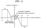
- Patent Document 1 controls the charging/discharging of the electric energy storage device in accordance with a charging rate SOC of an electric energy storage element used in the electric energy storage device and the line voltage. For example, as illustrated in FIG. 11 , it is necessary in some cases to set a floating control mode between a discharging start voltage Vc and a charging start voltage Vd for adjustment charging.
- the floating current If is caused to flow in the charging direction within the line voltage range from the discharging start voltage Vc to the charging start voltage Vd where no charging/discharging current flows in general. Accordingly, the charging/discharging current is controlled so as to maintain the charging rate to be a constant value.
- Such a conventional technology is a scheme of adjusting charging/discharging so as to obtain a desired charging rate at a voltage when the feeder line is in a slightly loaded condition. Accordingly, it becomes possible to maintain the charging rate of the electric energy storage element to be an arbitrary value.
- a current from the rectifier is once accumulated in the electric energy storage element in a slightly loaded condition, and is discharged again.
- a charging/discharging loss is caused, which is not suitable from the standpoint of energy saving.
- charging/discharging is not performed within a range from the discharging start voltage Vc to the charging start voltage Vd, however, as a result of the floating control, charging/discharging is performed even within the range.
- the charging/discharging cycles of the electric energy storage device increase. This results in the increase of an RMS current, a temperature rise of the electric energy storage element, and the increase of the charging/discharging cycle energy, and thus the lifetime of the element is reduced.
- the electric energy storage element used in the electric energy storage device has disadvantages such that the element does not have an excellent durability against heat, and the lifetime of the element is reduced when a deep charging/discharging depth is set.
- the same is true of the electric circuit substrate with respect to the durability against heat, and heat generation largely affects the lifetime of the substrate, resulting in a reduction of the reliability.
- DC power distributing systems other than the feeder system for a DC electric railroad such as a power distributing system to a drive system of an elevator, and a charging/discharging system of a solar power generation (PV) device, likewise have the same disadvantages.
- PV solar power generation
- An embodiment of the present invention has been made in order to address the above-explained disadvantages of the conventional technology. That is, it is an object of an embodiment of the present invention to provide an electric energy storage device which can enhance a reliability and a redundancy, and which can accomplish both long-life of a feeder system and energy saving.
- a first embodiment will be specifically explained with reference to FIG. 1 .
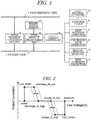
- FIG. 1 illustrates a whole structure of a feeder system including an electric energy storage device according to this embodiment.
- the power from a transmission line 1 is converted by a power converter device 2 at the transmission line side, and the DC power is supplied to a feeder line 3.
- the rated voltage of the feeder line 3, that is a DC power source is a voltage when the power converter device 2 at the transmission-line side is outputting a current that permits a successive operation.
- the power converter device 2 at the transmission-line-1 side includes a diode rectifier or a PWM converter, etc.
- Voltages of the feeder line 3 are, for example, DC 600 V, 750 V, 1500 V, and DC 3000 V, and a voltage fluctuation occurs at voltages therearound.
- the feeder line 3 is connected with an electric energy storage element 4 for storing electric energy through a power converter device 5 provided at the side of the electric energy storage element.
- the electric energy storage element 4 is, for example, a battery like a lithium-ion battery or a nickel hydride battery. Moreover, an electric double-layer capacitor can be available as the electric energy storage element 4.
- the power converter device 5 at the side of the electric energy storage element is, for example, a booster/step-down chopper circuit that controls switching elements through respective gates, and is capable of arbitrarily controlling charging/discharging currents to the electric energy storage element 4.
- the element used for this power converter device 5 is a self-turn-off element like an IGBT, which is subjected to a PWM drive, thereby controlling charging/discharging currents to the electric energy storage element 4.
- Multiple power converter devices 5 may be connected to the feeder line so as to operate the multiplexed electric energy storage element 4.
- Charging/discharging currents input to and output from the electric energy storage element 4 relative to the feeder line 3 by the power converter device 5 at the side of the electric energy storage element is set by an output current controller 6 provided on the power converter device 5.
- the output current controller 6 is connected with a line-voltage detector 7 that detects a line voltage (Line_Voltage) of the feeder line 3, and is connected with a charging-rate detector 8 that detects a charging rate SOC of the electric energy storage element 4.
- the output current controller 6 is connected with a control table 9 which determines, based on the line voltage and the charging rate detected by the line-voltage detector 7 and the charging-rate detector 8, the charging/discharging operations of the electric energy storage element 4, i.e., charging/discharging start voltages (charge_th_Low, discharge_th_high), and charging/discharging current saturated voltages (charge_th_high, discharge_th_low).
- the control table 9 is provided with a data inputter/outputter 10 which permits a user to set various values to be stored in the control table 9 and which is for checking the set values, input/output currents, and other data.
- the output current controller 6 changes the charging/discharging currents (Output Current) of the power converter device 5 at the side of the electric energy storage element side in accordance with a detected line voltage (Line_Voltage), the charging rate SOC, and a charging/discharging characteristic set in the control table 9.
- Line_Voltage detected line voltage
- SOC charging rate
- Charging/discharging characteristic set in the control table 9 An explanation will now be given of the charging/discharging characteristic set in the control table 9 with reference to FIGS. 2 to 4 .
- FIG. 2 illustrates a relationship between the line voltage (Line_Voltage) that is a horizontal axis and an output current (Output Current) of the electric energy storage element 4 that is a vertical axis. That is, when the line voltage becomes lower than a preset value (the center of the graph horizontal axis) and reaches the discharging start voltage (discharge_th_high), the output current from the electric energy storage element 4 increases, and after the line voltage reaches the discharging current saturated voltage (discharge_th_low), the discharging current maintained at the maximum value is kept being output.
- a preset value the center of the graph horizontal axis
- discharge_th_high the discharging start voltage
- discharge_th_low the discharging current saturated voltage
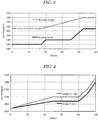
- FIG. 3 illustrates an example of discharging characteristic based on the line voltage (Line_Voltage) and the charging rate SOC.
- the charging characteristic discharge_th_high, discharge_th_low
- the discharging start voltage discharge_th_high
- the charging rate is set to be low at a lower range of the charging rate (equal to or lower than 40 % in the figure) so as not to start discharging as long as the line voltage does not become low.
- the discharging current saturated voltage (discharge_th_low) is set to be low at a lower range of the charging rate (equal to or lower than 40 % in the figure) so as to cause the maximum discharging current to flow at the low line voltage.
- discharge_th_low is set to be low at a lower range of the charging rate (equal to or lower than 40 % in the figure) so as to cause the maximum discharging current to flow at the low line voltage.
- the discharging start voltage (discharge_th_high) is set to be high (1450 V) so as to start discharging even the line voltage is high.
- the discharging current saturated voltage (discharge_th_low) is set to be high so as to allow the maximum discharging current to flow at a high line voltage (1500 V).
- FIG. 4 is an example of discharging characteristic based on the line voltage (Line_Voltage) and the charging rate SOC.
- a characteristic is set in such a way that the set values of the charging start voltage (charge_th_low) and the charging current saturated voltage (charge_th_high) become high as the charging rate becomes high, and the set values become low as the charging rate becomes low relative to the line voltage.
- the highest value of the discharging start voltage (discharge_th_high) in FIG. 3 is 1500 V
- the lowest value of the charging start voltage (charge_th_low) in FIG. 4 is 1620 V. That is, according to this embodiment, regardless of the range of the charging rate being present, no charging/discharging is performed at least within a range where the line voltage is from 1500 V to 1620 V.
- the characteristic transitions so as to facilitate discharging even at a high line voltage as the charging rate becomes high, and to cause less charging at the low line voltage. Conversely, as the charging rate becomes low, the characteristic transitions so as to cause less discharging at the low line voltage, and to facilitate charging at the low line voltage.
- charging/discharging operations like the floating current control, become unnecessary within a range where charging/discharging is not needed essentially. Frequent charging/discharging to the electric energy storage element is suppressed, thereby accomplishing the energy saving and the longer lifetime. That is, since the conventional adjustment of charging/discharging ,like the floating control, is not performed, no waste charging/discharging cycle energy is produced, thereby extending the lifetime of the electric energy storage element.
- charging is preferentially performed from a voltage range where regeneration is highly possibly canceled (e.g. , when the rated line voltage of the feeder line is DC 1500 V, a range from 1650 V to 1800 V), and discharging is intensively performed at a range where the feeder voltage becomes low, excessive regenerative energy can be absorbed, and a power feeding loss in the feeder system (a loss caused in the feeder line and in a rail where a return current flows) can be suppressed.
- a voltage range where regeneration is highly possibly canceled e.g. , when the rated line voltage of the feeder line is DC 1500 V, a range from 1650 V to 1800 V
- discharging is intensively performed at a range where the feeder voltage becomes low, excessive regenerative energy can be absorbed, and a power feeding loss in the feeder system (a loss caused in the feeder line and in a rail where a return current flows) can be suppressed.
- the above-explained first embodiment may employ the following modified example.
- FIG. 5 illustrates a second embodiment.
- a second power source 11 is connected to the electric energy storage element 4.
- power generators such as solar power generator may be used, wind power generator, and hydro-power generator.
- Both DC power source and AC power source are available as the second power source 11.
- the output power thereof is directly input into the electric energy storage element 4.
- the second power source is an AC power source, an AC power obtained by rectifying an original output power is supplied to the electric energy storage element 4.
- the output current controller 6 adjusts the charging/discharging characteristics from the feeder line 3 in accordance with the charging rate SOC and the line voltage detected by the detectors 7 and 8, and the set values in the control table 9. That is, direct connection of the second power source 11 to the electric energy storage element 4 causes the charging rate of the electric energy storage element 4 to be changed from moment to moment by the power from the second power source 11.
- the output current controller 6 refers to both charging rate changing from moment to moment as well as changing line voltage so as to control charging/discharging. Accordingly, the same advantage as that of the first embodiment can be expected.
- the power from the second power source 11 can be used for compensating the feeder voltage, the feeder loss is further reduced, and the energy saving effect can be further enhanced.
- the second power source 11 must not be directly connected to the electric energy storage element 4.
- the second power source 11 can be connected to the DC feeder line 3 connected with the electric energy storage element 4 near the electric energy storage element 4.
- the second power source 11 accomplishes the same function as a regenerative vehicle connected to the feeder line 3, and the same advantage as that of the first embodiment can be expected.
- the electric energy storage element 4 can be configured by a plurality of electric energy storage elements. More specifically, as illustrated in FIG. 7 , a large number of electric energy storage elements 4 (hereinafter, referred to as an electric energy storage element module) connected in series are connected in multiple rows in parallel. In this case, each electric energy storage element module may be configured to be released from the system through a release contactor 4a. However, in order to detect how many modules are released among the plurality of electric energy storage element modules, as illustrated in FIG. 1 , a detector 12 is connected to the output current controller 6, and the output current controller 6 restricts charging/discharging currents supplied to the power converter device 5 for the electric energy storage elements in accordance with the number of detected modules.
- the output current is restricted by multiplying the output current instruction generated by the output current controller 6 by a value obtained by dividing the number of parallel rows of the electric energy storage element modules after the release by the number of parallel rows of the electric energy storage element modules connected before the release. Accordingly, the modules can be kept in use without increasing the temperature of each electric energy storage element configuring the module.
- an output current instruction in accordance with the number of released electric energy storage element modules may be stored in the control table 9 in advance as a database, and the database may be referred in accordance with the number of released electric energy storage element modules to determine the maximum output current.
- the output current instruction of the power converter device 5 by the output current controller 6 may be restricted by the output current controller based on the RMS (effective value) current of the electric energy storage element 4, the RMS current of the power converter device 5, and a temperature detected at the electric energy storage element 4.
- RMS effective value
- an integration cycle of the RMS current may be set for each time slot to calculate the RMS current.
- the regenerative vehicle basically connected to the feeder line has a cyclic nature in its operation diagram, and thus an RMS current having that diagram cycle as an integration time period can be calculated.
- the output current controller 6 is provided with an RMS current detector 13 for the electric energy storage element 4 or the power converter device 5 as illustrated in FIG. 1 . Furthermore, a characteristic is set in the control table 9, the characteristic restricting the charging/discharging currents of the electric energy storage element 4 as the detected RMS current becomes close to a preset value set in advance. More specifically, as is indicated by the dotted lines in FIG. 8 , the characteristic that restricts a discharging stop voltage (Low_Limiter), the discharging current saturated voltage (discharge_th_low), the charging start voltage (charge_th_low), the charging current saturated voltage (charge_th_high), and a charging stop voltage (high_Limiter) is set in the control table 9.
- the current limiting characteristic on the basis of the RMS current may be changed in accordance with the temperature of the electric energy storage element and an external temperature. That is, the characteristic in FIG. 8 differs for each temperature of the electric energy storage element and each external temperature, and therefore different charging/discharging characteristics can be set for each temperature. Accordingly, even if the battery temperature and the external temperature rise, it does not deteriorate the lifetime of the electric energy storage element.
- the electric energy storage device of this embodiment can be installed at an arbitrary location. According to a fourth embodiment illustrated in FIG. 9 , however, the electric energy storage device located closer to a feeder transformer station, the discharging current saturated voltage (discharge_th_low) or the discharging start voltage (discharge_th_high) are set to be a higher value on the line voltage axis. That is, FIG. 9 illustrates an example of a feeder system of rated DC 1500 V, and the electric energy storage devices located near the feeder transformer stations 14a and 14b have the discharging current saturated voltage (discharge_th_low) or the discharging start voltage (discharge_th_high) set to be 1590 V. In contrast, the electric energy storage devices located at distant locations from the feeder transformer stations 14a and 14b have the discharging current saturated voltage (discharge_th_low) or the discharging start voltage (discharge_th_high) set to be 1500 V.
- the location on the feeder line 3 having the larger feeder voltage drop and distant from the feeder transformer station has lower discharging current saturated voltage or the discharging start voltage to the feeder line 3 from the electric energy storage device, thereby compensating the voltage drop of the feeder line 3.
- a fifth embodiment illustrated in FIG. 10 causes the electric energy storage device to have a larger capacity as becoming more distant from the feeder transformer stations 14a, 14b. According to such a fifth embodiment, the feeder loss caused by the flow of the feeder current can be reduced, thereby enhancing the energy saving effect. In this case, regarding the way of increasing the capacity of the electric energy storage device, the more distant the electric energy storage device is from the transformer station, the larger the number of electric energy storage device operated in parallel becomes, thereby increasing the capacity.
- each electric energy storage device of this embodiment may be installed at a station, and in this case, the electric energy storage device having a larger capacity is installed at a station having a larger number of stopping trains, thereby accomplishing a large energy saving effect.
- the large-capacity and high-output electric energy storage device is installed at a station having a small number of stopping trains, the regenerative energy of the distant train is excessively absorbed, and thus the energy saving effect is deteriorated due to the increase of the feeder line loss.
- the electric energy storage device having a larger capacity and a high output at a station having a larger number of stopping trains the reduction effect of the feeder line loss can be enhanced, thereby realizing an effective energy saving of the feeder system.
- the respective embodiments explained above utilize the feeder line connected with a regenerative railroad vehicle as the DC power source, but the present disclosure is applicable to DC distributing systems other than the feeder system of the DC electric railroad, such as a distributing system to a drive system of an elevator, and charging/discharging systems of a solar power generator (PV) .
- DC distributing systems other than the feeder system of the DC electric railroad, such as a distributing system to a drive system of an elevator, and charging/discharging systems of a solar power generator (PV) .
- PV solar power generator
Description
- The present disclosure relates to an electric energy storage device that is utilized as, for example, a power supply source for a DC electric railroad, and an installation-operation method of such an electric energy storage device.
- Conventionally, DC feeder systems are known as power supply systems for a DC electric railroad. Such DC feeder systems have characteristics that a load change due to start and stop of a railroad vehicle frequently occurs, and the line voltage change is large.
- It is typical that DC is produced from an AC power source system using a power converter like a diode rectifier, and power regeneration to the AC power source system at the deceleration of a railroad vehicle cannot be performed without an installation of a regenerative inverter. Hence, when no regenerative inverter is present, it is difficult to perform effective regeneration unless a sufficient load that absorbs regenerative currents from the railroad vehicle is present around the railroad vehicle.
- Conversely, even if the regenerative inverter is installed, if there is no load that consumes power regenerated by the inverter in the system, the regenerative power causes a reverse power flow to the power transmission-distribution system of an electric power company, and thus it is difficult for the railway business operator to accomplish an effect of reducing the amount of power to be purchased.
- In order to address such a disadvantage, an electric energy storage device that absorbs regenerative power of the vehicle is installed in the feeder system in some cases . This electric energy storage device is capable of absorbing the regenerative power of a railroad vehicle, and also capable of discharging the stored energy. The installation of the electric energy storage device enables a reduction of the input energy of the transformer station for power feeding. Moreover, some electric energy storage devices have a function of suppressing a change in a line voltage. An example prior art document for such an electric energy storage system is as follow:
- Patent Document 1:
JP 2006-62489 A - The technology disclosed in
Patent Document 1 controls the charging/discharging of the electric energy storage device in accordance with a charging rate SOC of an electric energy storage element used in the electric energy storage device and the line voltage. For example, as illustrated inFIG. 11 , it is necessary in some cases to set a floating control mode between a discharging start voltage Vc and a charging start voltage Vd for adjustment charging. - According to this conventional technology, when a line voltage V becomes high, a charging current is increased from the charging start voltage Vd to a charging current saturated voltage Ve, and the electric energy storage element SOC is charged by a maximum charging current Ic from the feeder line until the voltage reaches a charging maximum voltage Vf from the charging current saturated voltage Ve. Conversely, when the line voltage V becomes low, the discharging current is increased from the discharging start voltage Vc to a discharging current saturated voltage Vb, and discharging from the electric energy storage element SOC to the feeder line is performed by a maximum discharging current Io until the voltage reaches a discharging maximum voltage Va from the discharging current saturated voltage Vb.
- In this case, when the charging rate SOC is at the pre-set value, no charging/discharging current flows within the line voltage range from the discharging start voltage Vc to the charging start voltage Vd in the graph of
FIG. 11 . According to the conventional technology setting the floating control mode, however, when the charging rate SOC is higher than the pre-set value, a floating current If is caused to flow in the discharging direction (an output current I increases) within the line voltage range from the discharging start voltage Vc to the charging start voltage Vd where no charging/discharging current flows in general. Conversely, when the charging rate SOC is lower than the pre-set value, the floating current If is caused to flow in the charging direction within the line voltage range from the discharging start voltage Vc to the charging start voltage Vd where no charging/discharging current flows in general. Accordingly, the charging/discharging current is controlled so as to maintain the charging rate to be a constant value. - Such a conventional technology is a scheme of adjusting charging/discharging so as to obtain a desired charging rate at a voltage when the feeder line is in a slightly loaded condition. Accordingly, it becomes possible to maintain the charging rate of the electric energy storage element to be an arbitrary value. However, in this case, a current from the rectifier is once accumulated in the electric energy storage element in a slightly loaded condition, and is discharged again. Hence, a charging/discharging loss is caused, which is not suitable from the standpoint of energy saving. Moreover, generally, charging/discharging is not performed within a range from the discharging start voltage Vc to the charging start voltage Vd, however, as a result of the floating control, charging/discharging is performed even within the range. Thus, the charging/discharging cycles of the electric energy storage device increase. This results in the increase of an RMS current, a temperature rise of the electric energy storage element, and the increase of the charging/discharging cycle energy, and thus the lifetime of the element is reduced.
- In another way, in order to realize a high-output electric energy storage device, a large number of electric energy storage elements are connected in series and in parallel, but when a large number of elements are connected, there is a disadvantage that the reliability of the device decreases. When a large number of elements are connected in series, basically, a substrate for monitoring the charging rate of each element becomes necessary, and when the respective elements are connected in series and in parallel, the number of this monitoring substrates increases , resulting in a decrease of the reliability of the whole system. Moreover, the use of a large number of elements and monitoring substrates results in the increase of the device costs.
- Furthermore, the electric energy storage element used in the electric energy storage device has disadvantages such that the element does not have an excellent durability against heat, and the lifetime of the element is reduced when a deep charging/discharging depth is set. The same is true of the electric circuit substrate with respect to the durability against heat, and heat generation largely affects the lifetime of the substrate, resulting in a reduction of the reliability.
- DC power distributing systems other than the feeder system for a DC electric railroad, such as a power distributing system to a drive system of an elevator, and a charging/discharging system of a solar power generation (PV) device, likewise have the same disadvantages.
- An embodiment of the present invention has been made in order to address the above-explained disadvantages of the conventional technology. That is, it is an object of an embodiment of the present invention to provide an electric energy storage device which can enhance a reliability and a redundancy, and which can accomplish both long-life of a feeder system and energy saving.
- The invention is defined in the independent claim. Advantageous embodiments are set out in the dependent claims. Aspects or embodiments that do not fall under the scope of the claims are useful to understand the invention.
-
-
FIG. 1 is a block diagram illustrating a first embodiment; -
FIG. 2 is a graph indicating a relationship between a line voltage and an output current according to the first embodiment; -
FIG. 3 is a graph indicating a discharging characteristic according to the first embodiment; -
FIG. 4 is a graph illustrating a charging characteristic according to the first embodiment; -
FIG. 5 is a block diagram illustrating a second embodiment; -
FIG. 6 is a block diagram illustrating a modified example of the second embodiment; -
FIG. 7 is a wiring diagram illustrating a connection structure of an electric energy storage element according to each embodiment; -
FIG. 8 is a graph indicating a restricted characteristic of input/output currents according to a third embodiment; -
FIG. 9 is a graph indicating a relationship between an installation location of an electric energy storage device and a charging/discharging control characteristic according to a fourth embodiment; -
FIG. 10 is a graph indicating a relationship between an installation location of an electric energy storage device and a capacity of electric energy storage device according to a fifth embodiment; and -
FIG. 11 is a graph indicating a relationship between a line voltage of a conventional technology with a floating control mode and an output current. - Embodiments will be explained below with reference to the accompanying drawings.
- A first embodiment will be specifically explained with reference to
FIG. 1 . -
FIG. 1 illustrates a whole structure of a feeder system including an electric energy storage device according to this embodiment. According to the feeder system of this embodiment, the power from atransmission line 1 is converted by apower converter device 2 at the transmission line side, and the DC power is supplied to afeeder line 3. In this case, the rated voltage of thefeeder line 3, that is a DC power source, is a voltage when thepower converter device 2 at the transmission-line side is outputting a current that permits a successive operation. Thepower converter device 2 at the transmission-line-1 side includes a diode rectifier or a PWM converter, etc. Voltages of thefeeder line 3 are, for example,DC 600 V, 750 V, 1500 V, and DC 3000 V, and a voltage fluctuation occurs at voltages therearound. - The
feeder line 3 is connected with an electricenergy storage element 4 for storing electric energy through apower converter device 5 provided at the side of the electric energy storage element. The electricenergy storage element 4 is, for example, a battery like a lithium-ion battery or a nickel hydride battery. Moreover, an electric double-layer capacitor can be available as the electricenergy storage element 4. Thepower converter device 5 at the side of the electric energy storage element is, for example, a booster/step-down chopper circuit that controls switching elements through respective gates, and is capable of arbitrarily controlling charging/discharging currents to the electricenergy storage element 4. The element used for thispower converter device 5 is a self-turn-off element like an IGBT, which is subjected to a PWM drive, thereby controlling charging/discharging currents to the electricenergy storage element 4. Multiplepower converter devices 5 may be connected to the feeder line so as to operate the multiplexed electricenergy storage element 4. - Charging/discharging currents (Output Current) input to and output from the electric
energy storage element 4 relative to thefeeder line 3 by thepower converter device 5 at the side of the electric energy storage element is set by an outputcurrent controller 6 provided on thepower converter device 5. The outputcurrent controller 6 is connected with a line-voltage detector 7 that detects a line voltage (Line_Voltage) of thefeeder line 3, and is connected with a charging-rate detector 8 that detects a charging rate SOC of the electricenergy storage element 4. - The output
current controller 6 is connected with a control table 9 which determines, based on the line voltage and the charging rate detected by the line-voltage detector 7 and the charging-rate detector 8, the charging/discharging operations of the electricenergy storage element 4, i.e., charging/discharging start voltages (charge_th_Low, discharge_th_high), and charging/discharging current saturated voltages (charge_th_high, discharge_th_low). The control table 9 is provided with a data inputter/outputter 10 which permits a user to set various values to be stored in the control table 9 and which is for checking the set values, input/output currents, and other data. - The output
current controller 6 changes the charging/discharging currents (Output Current) of thepower converter device 5 at the side of the electric energy storage element side in accordance with a detected line voltage (Line_Voltage), the charging rate SOC, and a charging/discharging characteristic set in the control table 9. An explanation will now be given of the charging/discharging characteristic set in the control table 9 with reference toFIGS. 2 to 4 . -
FIG. 2 illustrates a relationship between the line voltage (Line_Voltage) that is a horizontal axis and an output current (Output Current) of the electricenergy storage element 4 that is a vertical axis. That is, when the line voltage becomes lower than a preset value (the center of the graph horizontal axis) and reaches the discharging start voltage (discharge_th_high), the output current from the electricenergy storage element 4 increases, and after the line voltage reaches the discharging current saturated voltage (discharge_th_low), the discharging current maintained at the maximum value is kept being output. Conversely, when the line voltage becomes higher than the preset value (center of the graph horizontal axis) and reaches the charging start voltage (charge_th_low), the charging current to the electricenergy storage element 4 increases, and after the line voltage reaches the charging current saturated voltage (charge_th_high), charging is performed with the charging current being maintained at the maximum value. -
FIG. 3 illustrates an example of discharging characteristic based on the line voltage (Line_Voltage) and the charging rate SOC. As illustrated inFIG. 3 , according to this embodiment, the charging characteristic (discharge_th_high, discharge_th_low) is set within a line voltage range from 1380 V to 1500 V. In this case, the discharging start voltage (discharge_th_high) is set to be low at a lower range of the charging rate (equal to or lower than 40 % in the figure) so as not to start discharging as long as the line voltage does not become low. Likewise, the discharging current saturated voltage (discharge_th_low) is set to be low at a lower range of the charging rate (equal to or lower than 40 % in the figure) so as to cause the maximum discharging current to flow at the low line voltage. As a result, setting is made in such a way that no discharging is performed at the lower range of the charging rate as long as the line voltage does not become low (equal to or lower than 1450 V). - Conversely, at a higher range of the charging rate (equal to or greater than 85 % in the figure), the discharging start voltage (discharge_th_high) is set to be high (1450 V) so as to start discharging even the line voltage is high. Likewise, at the higher range of the charging rate (equal to or greater than 85 % in the figure), the discharging current saturated voltage (discharge_th_low) is set to be high so as to allow the maximum discharging current to flow at a high line voltage (1500 V).
-
FIG. 4 is an example of discharging characteristic based on the line voltage (Line_Voltage) and the charging rate SOC. As illustrated inFIG. 4 , a characteristic is set in such a way that the set values of the charging start voltage (charge_th_low) and the charging current saturated voltage (charge_th_high) become high as the charging rate becomes high, and the set values become low as the charging rate becomes low relative to the line voltage. As a result, when the charging rate of the electricenergy storage element 4 is low, charging is started although the line voltage is low, and when the charging rate is high, no charging is performed unless the line voltage becomes high. - According to this embodiment, within the all range of the charging rate, the highest value of the discharging start voltage (discharge_th_high) in
FIG. 3 is 1500 V, and the lowest value of the charging start voltage (charge_th_low) inFIG. 4 is 1620 V. That is, according to this embodiment, regardless of the range of the charging rate being present, no charging/discharging is performed at least within a range where the line voltage is from 1500 V to 1620 V. - The above-explained charging/discharging characteristics of this embodiment illustrated in
FIGS. 3 and 4 are indicated by dotted lines in the graph ofFIG. 2 . As is clear from the dotted lines, according to this embodiment, when the charging rate SOC of the electric energy storage element changes, unlike the conventional technology illustrated inFIG. 11 , no floating current If is caused to flow within a portion from the discharging start voltage (discharge_th_high) to the charging start voltage (charge_th_low) . According to this embodiment, at least one of the charging start voltage (discharge_th_high) and the charging start voltage (charge_th_low) is changed in accordance with the charging rate. Accordingly, the outputcurrent controller 6 refers to the control table inFIG. 3 or FIG. 4 , terminates charging/discharging operations when the line voltage is within a range from the discharging start voltage (discharge_th_high) to the charging start voltage (charge_th_low), and can perform appropriate charging/discharging operations in accordance with the charging rate SOC and the line voltage within a range where the line voltage is higher than a rated voltage by a preset voltage or is lower than the rated voltage by the preset voltage. - As explained above, according to this embodiment, the characteristic transitions so as to facilitate discharging even at a high line voltage as the charging rate becomes high, and to cause less charging at the low line voltage. Conversely, as the charging rate becomes low, the characteristic transitions so as to cause less discharging at the low line voltage, and to facilitate charging at the low line voltage.
- As a result, according to this embodiment, charging/discharging operations, like the floating current control, become unnecessary within a range where charging/discharging is not needed essentially. Frequent charging/discharging to the electric energy storage element is suppressed, thereby accomplishing the energy saving and the longer lifetime. That is, since the conventional adjustment of charging/discharging ,like the floating control, is not performed, no waste charging/discharging cycle energy is produced, thereby extending the lifetime of the electric energy storage element.
- Moreover, charging is preferentially performed from a voltage range where regeneration is highly possibly canceled (e.g. , when the rated line voltage of the feeder line is
DC 1500 V, a range from 1650 V to 1800 V), and discharging is intensively performed at a range where the feeder voltage becomes low, excessive regenerative energy can be absorbed, and a power feeding loss in the feeder system (a loss caused in the feeder line and in a rail where a return current flows) can be suppressed. - The above-explained first embodiment may employ the following modified example.
- (1) According to this embodiment, it is not always necessary to change both of the charging start voltage (charge_th_low) and the discharging start voltage (discharge_th_high) in accordance with the charging rate. Either one voltage may be maintained as a fixed value, and the other of the charging start voltage (charge_th_low) or the discharging start voltage (discharge_th_high) may be changed in accordance with the charging rate. The same advantage can be also accomplished in this case.
- (2) When the set values of the charging current saturated voltage (charge_th_high) and the charging start voltage (charge_th_low) are set to be equal to or lower than a no-load feeding voltage of a transformer station regardless of the charging rate SOC, charging from the transformer station in a slightly-loaded condition is enabled. This is effective for a line where regenerative energy level is extremely low, and charging can be performed in advance when the feeder system is in a slightly-loaded condition.
- (3) Contrary to the above-explained (2), in the case of a system in which regenerative energy can be expected, the set values can be set to be equal to or higher than the no-load feeding voltage of a transformer station, and thus the charging rate can be adjusted by charging based on only the regenerative energy. This suppresses a charging and discharging of feeder energy of the transformer station to the electric energy storage element in a case that no regenerative energy from a train is present, thereby suppressing a deterioration of the feeder efficiency.
- (4) The discharging current saturated voltage (discharge_th_low) and the discharging start voltage (discharge_th_high) are set to be active at a voltage equal to or lower than a feeder line rated voltage (e.g., 1500 V in the case of a feeder system of
DC 1500 V). By this, the discharging is intensively performed in a condition in which the line voltages really drops largely so as to compensate the line voltage drop, thereby reducing the feeder loss. - (5) In order to decrease the loss of the
power converter device 5 at the side of the electricenergy storage element 4 between line voltages where no charging/discharging is performed (from discharging start voltage (discharge_th_high) to charging start voltage (charge_th_low)) to accomplish the energy saving, the booster/step-down chopper circuit of thepower converter device 5 may be subjected to gate blocking. -
FIG. 5 illustrates a second embodiment. According to the second embodiment, asecond power source 11 is connected to the electricenergy storage element 4. As an example of thesecond power sources 11, power generators, such as solar power generator may be used, wind power generator, and hydro-power generator. Both DC power source and AC power source are available as thesecond power source 11. In the case of the DC power source, the output power thereof is directly input into the electricenergy storage element 4. When the second power source is an AC power source, an AC power obtained by rectifying an original output power is supplied to the electricenergy storage element 4. - When power is supplied to the electric
energy storage element 4 from thesecond power source 11, like the above-explained first embodiment, the outputcurrent controller 6 adjusts the charging/discharging characteristics from thefeeder line 3 in accordance with the charging rate SOC and the line voltage detected by thedetectors 7 and 8, and the set values in the control table 9. That is, direct connection of thesecond power source 11 to the electricenergy storage element 4 causes the charging rate of the electricenergy storage element 4 to be changed from moment to moment by the power from thesecond power source 11. In the embodiment illustrated inFIG. 5 , the outputcurrent controller 6 refers to both charging rate changing from moment to moment as well as changing line voltage so as to control charging/discharging. Accordingly, the same advantage as that of the first embodiment can be expected. In particular, the power from thesecond power source 11 can be used for compensating the feeder voltage, the feeder loss is further reduced, and the energy saving effect can be further enhanced. - In the second embodiment, the
second power source 11 must not be directly connected to the electricenergy storage element 4. As illustrated inFIG. 6 , , thesecond power source 11 can be connected to theDC feeder line 3 connected with the electricenergy storage element 4 near the electricenergy storage element 4. In this case, thesecond power source 11 accomplishes the same function as a regenerative vehicle connected to thefeeder line 3, and the same advantage as that of the first embodiment can be expected. - In the respective embodiments explained above, the electric
energy storage element 4 can be configured by a plurality of electric energy storage elements. More specifically, as illustrated inFIG. 7 , a large number of electric energy storage elements 4 (hereinafter, referred to as an electric energy storage element module) connected in series are connected in multiple rows in parallel. In this case, each electric energy storage element module may be configured to be released from the system through arelease contactor 4a. However, in order to detect how many modules are released among the plurality of electric energy storage element modules, as illustrated inFIG. 1 , adetector 12 is connected to the outputcurrent controller 6, and the outputcurrent controller 6 restricts charging/discharging currents supplied to thepower converter device 5 for the electric energy storage elements in accordance with the number of detected modules. - More specifically, the output current is restricted by multiplying the output current instruction generated by the output
current controller 6 by a value obtained by dividing the number of parallel rows of the electric energy storage element modules after the release by the number of parallel rows of the electric energy storage element modules connected before the release. Accordingly, the modules can be kept in use without increasing the temperature of each electric energy storage element configuring the module. Moreover, an output current instruction in accordance with the number of released electric energy storage element modules may be stored in the control table 9 in advance as a database, and the database may be referred in accordance with the number of released electric energy storage element modules to determine the maximum output current. - The output current instruction of the
power converter device 5 by the outputcurrent controller 6 may be restricted by the output current controller based on the RMS (effective value) current of the electricenergy storage element 4, the RMS current of thepower converter device 5, and a temperature detected at the electricenergy storage element 4. For example, regarding the above-explained RMS current, an integration cycle of the RMS current may be set for each time slot to calculate the RMS current. The regenerative vehicle basically connected to the feeder line has a cyclic nature in its operation diagram, and thus an RMS current having that diagram cycle as an integration time period can be calculated. - In this case, the output
current controller 6 is provided with an RMScurrent detector 13 for the electricenergy storage element 4 or thepower converter device 5 as illustrated inFIG. 1 . Furthermore, a characteristic is set in the control table 9, the characteristic restricting the charging/discharging currents of the electricenergy storage element 4 as the detected RMS current becomes close to a preset value set in advance. More specifically, as is indicated by the dotted lines inFIG. 8 , the characteristic that restricts a discharging stop voltage (Low_Limiter), the discharging current saturated voltage (discharge_th_low), the charging start voltage (charge_th_low), the charging current saturated voltage (charge_th_high), and a charging stop voltage (high_Limiter) is set in the control table 9. - The current limiting characteristic on the basis of the RMS current may be changed in accordance with the temperature of the electric energy storage element and an external temperature. That is, the characteristic in
FIG. 8 differs for each temperature of the electric energy storage element and each external temperature, and therefore different charging/discharging characteristics can be set for each temperature. Accordingly, even if the battery temperature and the external temperature rise, it does not deteriorate the lifetime of the electric energy storage element. - The electric energy storage device of this embodiment can be installed at an arbitrary location. According to a fourth embodiment illustrated in
FIG. 9 , however, the electric energy storage device located closer to a feeder transformer station, the discharging current saturated voltage (discharge_th_low) or the discharging start voltage (discharge_th_high) are set to be a higher value on the line voltage axis. That is,FIG. 9 illustrates an example of a feeder system of ratedDC 1500 V, and the electric energy storage devices located near thefeeder transformer stations feeder transformer stations - As a result, the location on the
feeder line 3 having the larger feeder voltage drop and distant from the feeder transformer station has lower discharging current saturated voltage or the discharging start voltage to thefeeder line 3 from the electric energy storage device, thereby compensating the voltage drop of thefeeder line 3. - A fifth embodiment illustrated in
FIG. 10 causes the electric energy storage device to have a larger capacity as becoming more distant from thefeeder transformer stations - Moreover, each electric energy storage device of this embodiment may be installed at a station, and in this case, the electric energy storage device having a larger capacity is installed at a station having a larger number of stopping trains, thereby accomplishing a large energy saving effect. Conversely, when the large-capacity and high-output electric energy storage device is installed at a station having a small number of stopping trains, the regenerative energy of the distant train is excessively absorbed, and thus the energy saving effect is deteriorated due to the increase of the feeder line loss. Hence, by installing the electric energy storage device having a larger capacity and a high output at a station having a larger number of stopping trains, the reduction effect of the feeder line loss can be enhanced, thereby realizing an effective energy saving of the feeder system.
- The above-explained embodiments are exhibited by way of example only in this specification, and are not intended to limit the scope of the present disclosures.
- In particular, the respective embodiments explained above utilize the feeder line connected with a regenerative railroad vehicle as the DC power source, but the present disclosure is applicable to DC distributing systems other than the feeder system of the DC electric railroad, such as a distributing system to a drive system of an elevator, and charging/discharging systems of a solar power generator (PV) .
-
- 1 Transmission line
- 2 power converter device at the side of the transmission line
- 3 Feeder line
- 4 Electric energy storage element
- 4a Release contactor
- 5 power converter device at the side of the electric energy storage element
- 6 Output current controller
- 7 Line voltage detector
- 8 Charging rate detector
- 9 Control table
- 10 Data inputter/outputter
- 11 Second power source
- 12 Detector for release contactor
- 13 RMS current detector
- 14a, 14b Feeder transformer station
Claims (9)
- An electric energy storage device comprising:an electric energy storage element (4) connected to a DC power source (3) via a power converter device (5); andan output current controller (6) which is connected to the power converter device and which is configured to control charging/discharging current of the electric energy storage element relative to the DC power source,the output current controller (6) being connected with a voltage detector (7) configured to detect a voltage of the DC power source, a charging rate detector (8) configured to detect a charging rate of the electric energy storage element, and a control table (9) having set therein charging/discharging characteristics, andthe charging / discharging characteristics are determined based on the voltage of the DC power source detected by the voltage detector (7) and the charging rate of the electric energy storage element detected by the charging rate detector (8),the voltage of the DC power source is selected from at least one of a charging start voltage, a discharging start voltage, a charging current saturated voltage and a discharging current saturated voltage of the electric energy storage element,the charging/discharging characteristics stored in the control table (9) being set such that at least one of the charging start voltage, the discharging start voltage, the charging current saturated voltage and the discharging current saturated voltage is set to a higher value at higher charging rate of the electric energy storage element than at lower charging rate thereof, and the output current controller is configured to terminate charging or discharging operations within a range from the discharging start voltage to the charging start voltage when charging rate of the electric energy storage element changes.
- The electric energy storage device according to claim 1, wherein
a power source voltage from the DC voltage is supplied through the power converter device (2) - configured to convert AC voltage to DC voltage,
a no-load feeding voltage of the DC power source changes in accordance with a change in the AC voltage, and
the charging/discharging characteristics stored in the control table is set such that the DC voltage of the DC power source performing a charging operation to the electric energy storage element is set to be higher than the voltage of the DC power source changed in accordance with the voltage change in the AC voltage. - The electric energy storage device according to claim 2, wherein a rated voltage of the DC power source is a DC power source voltage when the power converter device (2) that is a voltage source of the DC power source is outputting a current that enables a continuous operation.
- The electric energy storage device according to claim 1, wherein the power converter device (2) connected to the electric energy storage element comprises a plurality of power converters connected in parallel.
- The electric energy storage device according to any one of claims 1 to 4, wherein
the power converter device (2) connected to the electric energy storage element is a power converter device that is configured to operate through a gate drive on a switching element, and
the gate drive is terminated when the voltage of the DC power source is lower than the no-load feeding voltage and is higher than the rated voltage of the DC power source. - The electric energy storage device according to claim 1, wherein a second power source (11) is connected to at least one of the electric energy storage element and the DC power source.
- The electric energy storage device according to any one of claims 1 to 6, wherein the DC power source is a feeder line connected to a transformer station and a regenerative train.
- The electric energy storage device according to any one of claims 1 to 7, further comprising:a plurality of electric energy storage element series modules each including a plurality of the electric energy storage elements connected in series, the plurality of electric energy storage element series modules being connected in parallel;a release contactor provided between each of the plurality of electric energy storage element series modules connected in parallel and the power converter device; anda release contactor detector which is configured to detect a number of released electric energy storage element series module and which is provided at the output current controller,wherein the output current controller limits charging/discharging currents in accordance with the number of electric energy storage element series modules detected by the release contactor detector.
- The electric energy storage device according to any one of claims 1 to 8, further comprising a detector which is configured to detect at least one of a temperature of the electric energy storage element, an RMS current, and an external temperature and which is provided at the output current controller,
wherein the output current controller is configured to limit charging/discharging currents in accordance with at least one value of the temperature of the electric energy storage element, the RMS current, and the external temperature detected by the detector.
Applications Claiming Priority (2)
| Application Number | Priority Date | Filing Date | Title |
|---|---|---|---|
| JP2011028188A JP5377538B2 (en) | 2011-02-14 | 2011-02-14 | Power storage device and its installation / operation method |
| PCT/JP2012/053440 WO2012111679A1 (en) | 2011-02-14 | 2012-02-14 | Battery device and method for installing and operating same |
Publications (3)
| Publication Number | Publication Date |
|---|---|
| EP2676834A1 EP2676834A1 (en) | 2013-12-25 |
| EP2676834A4 EP2676834A4 (en) | 2018-05-02 |
| EP2676834B1 true EP2676834B1 (en) | 2020-09-02 |
Family
ID=46672596
Family Applications (1)
| Application Number | Title | Priority Date | Filing Date |
|---|---|---|---|
| EP12747709.9A Active EP2676834B1 (en) | 2011-02-14 | 2012-02-14 | Battery device and method for installing and operating same |
Country Status (7)
| Country | Link |
|---|---|
| US (1) | US9312717B2 (en) |
| EP (1) | EP2676834B1 (en) |
| JP (1) | JP5377538B2 (en) |
| KR (1) | KR101715444B1 (en) |
| CN (1) | CN103347733B (en) |
| HK (1) | HK1189198A1 (en) |
| WO (1) | WO2012111679A1 (en) |
Families Citing this family (24)
| Publication number | Priority date | Publication date | Assignee | Title |
|---|---|---|---|---|
| JP2014128152A (en) * | 2012-12-27 | 2014-07-07 | Panasonic Corp | Charge and discharge controller, charge and discharge control system and charge and discharge control method |
| CN103434420B (en) * | 2013-07-29 | 2016-02-17 | 华北电力大学(保定) | Based on the Brake energy recovery formula DC traction power-supply system of charging electric vehicle |
| CN105453373B (en) | 2013-08-09 | 2018-03-02 | 日立汽车系统株式会社 | Battery control system, vehicle control system |
| JP5735061B2 (en) | 2013-08-12 | 2015-06-17 | 株式会社東芝 | Train power supply system |
| US10020653B2 (en) | 2013-11-28 | 2018-07-10 | Mitsubishi Electric Corporation | Station-building power supply device |
| JP6293467B2 (en) * | 2013-12-03 | 2018-03-14 | 株式会社東芝 | DC power supply system |
| JP6189230B2 (en) * | 2014-02-25 | 2017-08-30 | 株式会社東芝 | Storage battery device and storage battery device control method |
| DE102014203903A1 (en) * | 2014-03-04 | 2015-09-10 | Volkswagen Aktiengesellschaft | Method and device for predicting a range change by switching on or off a vehicle function of a vehicle |
| JP6324122B2 (en) * | 2014-03-07 | 2018-05-16 | 株式会社日立製作所 | Power storage type voltage stabilizer and control method thereof |
| DE102014006028B4 (en) * | 2014-04-24 | 2022-06-30 | Audi Ag | Multi-battery system to increase the electric range |
| KR102253188B1 (en) * | 2014-08-01 | 2021-05-18 | 엘지이노텍 주식회사 | Apparatus for controlling rapid charging of electric vehicle |
| JP6552796B2 (en) | 2014-09-03 | 2019-07-31 | 株式会社東芝 | Power storage control device |
| JP6363465B2 (en) * | 2014-10-21 | 2018-07-25 | 株式会社東芝 | Power storage device |
| US10232732B2 (en) * | 2015-01-27 | 2019-03-19 | Ford Global Technologies, Llc | System and method for battery control using RMS current |
| JP6420684B2 (en) * | 2015-02-17 | 2018-11-07 | 株式会社日立製作所 | Power storage device |
| JP6407775B2 (en) * | 2015-03-13 | 2018-10-17 | 株式会社東芝 | Power storage device |
| JP6156667B1 (en) * | 2016-12-27 | 2017-07-05 | 富士電機株式会社 | Charge / discharge control device for power storage device and power storage system |
| JP6108142B1 (en) * | 2017-01-19 | 2017-04-05 | 富士電機株式会社 | Charge / discharge control device, charge / discharge control method, and power storage system for power storage device |
| IT201700011274A1 (en) * | 2017-02-02 | 2018-08-02 | Nidec Asi S P A | System and method for supplying a rail route. |
| JP7116581B2 (en) * | 2018-04-24 | 2022-08-10 | 株式会社東芝 | Feeder device and feeder system |
| JP7214993B2 (en) * | 2018-06-29 | 2023-01-31 | 株式会社リコー | storage system |
| JP7191873B2 (en) * | 2020-01-17 | 2022-12-19 | 株式会社東芝 | Charge/discharge control device, charge/discharge system, charge/discharge control method, and charge/discharge control program |
| RU2735158C1 (en) * | 2020-04-03 | 2020-10-28 | Федеральное государственное бюджетное образовательное учреждение высшего образования "Омский государственный университет путей сообщения" | Device for automatic control of traction power supply system |
| KR102450435B1 (en) * | 2021-12-07 | 2022-09-30 | 주식회사 풍성인더스 | Increasing solar power efficiency using self generative power with each circuit's earth leakage detection and method therefor |
Family Cites Families (15)
| Publication number | Priority date | Publication date | Assignee | Title |
|---|---|---|---|---|
| JPS5959528A (en) * | 1982-09-28 | 1984-04-05 | Hitachi Ltd | Method for controlling electric railway substation |
| JP2001260718A (en) * | 2000-03-16 | 2001-09-26 | Railway Technical Res Inst | Dc power supply facility for electric railroad |
| KR20050043732A (en) * | 2001-11-02 | 2005-05-11 | 아커 웨이드 파워 테크놀로지스 엘엘씨 | Fast charger for high capacity batteries |
| JP2006034041A (en) * | 2004-07-20 | 2006-02-02 | Toyo Electric Mfg Co Ltd | Controller for feeder system power storage system |
| JP4238190B2 (en) * | 2004-08-26 | 2009-03-11 | 株式会社日立製作所 | Power storage type regenerative power absorber and control method thereof |
| JP4252953B2 (en) * | 2004-11-26 | 2009-04-08 | 株式会社日立製作所 | Power storage type feeder voltage compensation apparatus and method |
| JP4583154B2 (en) * | 2004-12-13 | 2010-11-17 | 東洋電機製造株式会社 | Control device for feeder system power storage system |
| JP2008074180A (en) | 2006-09-20 | 2008-04-03 | Toyo Electric Mfg Co Ltd | Power storage system |
| JP2008154355A (en) * | 2006-12-18 | 2008-07-03 | Hitachi Ltd | Accumulation equipment |
| JP2009113691A (en) * | 2007-11-08 | 2009-05-28 | Kawasaki Heavy Ind Ltd | Ground power supply system of battery-driven type vehicle in railroad vehicle |
| EP2255992A4 (en) | 2008-02-29 | 2014-09-24 | Kawasaki Heavy Ind Ltd | Electric railway power-supply system |
| JP4958846B2 (en) | 2008-06-03 | 2012-06-20 | 株式会社日立製作所 | Vehicle control device for intermittent power reception |
| US8030884B2 (en) * | 2009-08-31 | 2011-10-04 | General Electric Company | Apparatus for transferring energy using onboard power electronics and method of manufacturing same |
| US8583311B2 (en) | 2010-07-30 | 2013-11-12 | Mitsubishi Heavy Industries, Ltd. | Overhead wire transportation system and control method thereof |
| JP5048824B2 (en) * | 2010-10-25 | 2012-10-17 | 三菱電機株式会社 | Vehicle power generation control device |
-
2011
- 2011-02-14 JP JP2011028188A patent/JP5377538B2/en active Active
-
2012
- 2012-02-14 US US13/985,455 patent/US9312717B2/en active Active
- 2012-02-14 CN CN201280007387.2A patent/CN103347733B/en active Active
- 2012-02-14 WO PCT/JP2012/053440 patent/WO2012111679A1/en active Application Filing
- 2012-02-14 EP EP12747709.9A patent/EP2676834B1/en active Active
- 2012-02-14 KR KR1020137022217A patent/KR101715444B1/en active IP Right Grant
-
2014
- 2014-03-05 HK HK14102201.5A patent/HK1189198A1/en unknown
Non-Patent Citations (1)
| Title |
|---|
| None * |
Also Published As
| Publication number | Publication date |
|---|---|
| KR20130120522A (en) | 2013-11-04 |
| EP2676834A4 (en) | 2018-05-02 |
| CN103347733B (en) | 2015-11-25 |
| BR112013020595A2 (en) | 2016-10-18 |
| JP5377538B2 (en) | 2013-12-25 |
| HK1189198A1 (en) | 2014-05-30 |
| US9312717B2 (en) | 2016-04-12 |
| WO2012111679A1 (en) | 2012-08-23 |
| US20140070770A1 (en) | 2014-03-13 |
| JP2012166646A (en) | 2012-09-06 |
| KR101715444B1 (en) | 2017-03-10 |
| EP2676834A1 (en) | 2013-12-25 |
| CN103347733A (en) | 2013-10-09 |
Similar Documents
| Publication | Publication Date | Title |
|---|---|---|
| EP2676834B1 (en) | Battery device and method for installing and operating same | |
| US10464441B2 (en) | Charging facility and energy management method for charging facility | |
| US7402982B2 (en) | Energy storage type feeder voltage compensation apparatus and method of controlling feeder voltage | |
| JP5028517B2 (en) | DC power supply system | |
| JP3964857B2 (en) | Regenerative power absorption control method for electric railways | |
| KR101252081B1 (en) | Line current and energy storage control for an elevator drive | |
| JP5005809B2 (en) | Power conversion control method and control device for fuel cell-battery hybrid electric vehicle | |
| US9365175B2 (en) | Power supply system for vehicle | |
| RU2660207C1 (en) | Device for energy storage | |
| JP5318004B2 (en) | Vehicle power supply system | |
| CN104508965A (en) | DC/DC power converter control strategy for source protection | |
| JP4432675B2 (en) | Power converter | |
| CN204928347U (en) | Automatic rescue of elevator and economizer and ultracapacitor system module | |
| WO2016196968A1 (en) | Utilizing a load for optimizing energy storage size and operation in power systems regulation applications | |
| JP5509442B2 (en) | Power converter and electric railway system | |
| US11613444B2 (en) | Decentralized power management in an elevator system | |
| JP2006204032A (en) | Voltage converter | |
| BR112013020595B1 (en) | ELECTRICAL ENERGY STORAGE DEVICE | |
| JP2004120846A (en) | Dc power supply system |
Legal Events
| Date | Code | Title | Description |
|---|---|---|---|
| PUAI | Public reference made under article 153(3) epc to a published international application that has entered the european phase |
Free format text: ORIGINAL CODE: 0009012 |
|
| 17P | Request for examination filed |
Effective date: 20130904 |
|
| AK | Designated contracting states |
Kind code of ref document: A1 Designated state(s): AL AT BE BG CH CY CZ DE DK EE ES FI FR GB GR HR HU IE IS IT LI LT LU LV MC MK MT NL NO PL PT RO RS SE SI SK SM TR |
|
| DAX | Request for extension of the european patent (deleted) | ||
| RIC1 | Information provided on ipc code assigned before grant |
Ipc: B60M 3/06 20060101AFI20171212BHEP Ipc: B60L 11/00 20060101ALI20171212BHEP Ipc: B60L 9/04 20060101ALI20171212BHEP Ipc: B60L 11/18 20060101ALI20171212BHEP Ipc: H02J 7/00 20060101ALI20171212BHEP |
|
| RIC1 | Information provided on ipc code assigned before grant |
Ipc: B60L 9/04 20060101ALI20180321BHEP Ipc: H02J 7/00 20060101ALI20180321BHEP Ipc: B60L 11/18 20060101ALI20180321BHEP Ipc: B60L 11/00 20060101ALI20180321BHEP Ipc: B60M 3/06 20060101AFI20180321BHEP |
|
| RA4 | Supplementary search report drawn up and despatched (corrected) |
Effective date: 20180403 |
|
| STAA | Information on the status of an ep patent application or granted ep patent |
Free format text: STATUS: EXAMINATION IS IN PROGRESS |
|
| 17Q | First examination report despatched |
Effective date: 20190705 |
|
| REG | Reference to a national code |
Ref country code: DE Ref legal event code: R079 Ref document number: 602012072105 Country of ref document: DE Free format text: PREVIOUS MAIN CLASS: B60M0003060000 Ipc: B60L0050200000 |
|
| GRAP | Despatch of communication of intention to grant a patent |
Free format text: ORIGINAL CODE: EPIDOSNIGR1 |
|
| STAA | Information on the status of an ep patent application or granted ep patent |
Free format text: STATUS: GRANT OF PATENT IS INTENDED |
|
| RIC1 | Information provided on ipc code assigned before grant |
Ipc: B60L 50/20 20190101AFI20200207BHEP Ipc: B60L 9/04 20060101ALI20200207BHEP Ipc: B60M 3/06 20060101ALI20200207BHEP Ipc: B60L 58/12 20190101ALI20200207BHEP Ipc: B60L 58/18 20190101ALI20200207BHEP |
|
| INTG | Intention to grant announced |
Effective date: 20200310 |
|
| RAP1 | Party data changed (applicant data changed or rights of an application transferred) |
Owner name: KABUSHIKI KAISHA TOSHIBA |
|
| GRAJ | Information related to disapproval of communication of intention to grant by the applicant or resumption of examination proceedings by the epo deleted |
Free format text: ORIGINAL CODE: EPIDOSDIGR1 |
|
| STAA | Information on the status of an ep patent application or granted ep patent |
Free format text: STATUS: EXAMINATION IS IN PROGRESS |
|
| GRAR | Information related to intention to grant a patent recorded |
Free format text: ORIGINAL CODE: EPIDOSNIGR71 |
|
| GRAS | Grant fee paid |
Free format text: ORIGINAL CODE: EPIDOSNIGR3 |
|
| STAA | Information on the status of an ep patent application or granted ep patent |
Free format text: STATUS: GRANT OF PATENT IS INTENDED |
|
| GRAA | (expected) grant |
Free format text: ORIGINAL CODE: 0009210 |
|
| STAA | Information on the status of an ep patent application or granted ep patent |
Free format text: STATUS: THE PATENT HAS BEEN GRANTED |
|
| INTC | Intention to grant announced (deleted) | ||
| AK | Designated contracting states |
Kind code of ref document: B1 Designated state(s): AL AT BE BG CH CY CZ DE DK EE ES FI FR GB GR HR HU IE IS IT LI LT LU LV MC MK MT NL NO PL PT RO RS SE SI SK SM TR |
|
| INTG | Intention to grant announced |
Effective date: 20200728 |
|
| REG | Reference to a national code |
Ref country code: GB Ref legal event code: FG4D |
|
| REG | Reference to a national code |
Ref country code: AT Ref legal event code: REF Ref document number: 1308454 Country of ref document: AT Kind code of ref document: T Effective date: 20200915 Ref country code: CH Ref legal event code: EP |
|
| REG | Reference to a national code |
Ref country code: DE Ref legal event code: R096 Ref document number: 602012072105 Country of ref document: DE |
|
| REG | Reference to a national code |
Ref country code: IE Ref legal event code: FG4D |
|
| REG | Reference to a national code |
Ref country code: LT Ref legal event code: MG4D |
|
| PG25 | Lapsed in a contracting state [announced via postgrant information from national office to epo] |
Ref country code: HR Free format text: LAPSE BECAUSE OF FAILURE TO SUBMIT A TRANSLATION OF THE DESCRIPTION OR TO PAY THE FEE WITHIN THE PRESCRIBED TIME-LIMIT Effective date: 20200902 Ref country code: FI Free format text: LAPSE BECAUSE OF FAILURE TO SUBMIT A TRANSLATION OF THE DESCRIPTION OR TO PAY THE FEE WITHIN THE PRESCRIBED TIME-LIMIT Effective date: 20200902 Ref country code: NO Free format text: LAPSE BECAUSE OF FAILURE TO SUBMIT A TRANSLATION OF THE DESCRIPTION OR TO PAY THE FEE WITHIN THE PRESCRIBED TIME-LIMIT Effective date: 20201202 Ref country code: GR Free format text: LAPSE BECAUSE OF FAILURE TO SUBMIT A TRANSLATION OF THE DESCRIPTION OR TO PAY THE FEE WITHIN THE PRESCRIBED TIME-LIMIT Effective date: 20201203 Ref country code: LT Free format text: LAPSE BECAUSE OF FAILURE TO SUBMIT A TRANSLATION OF THE DESCRIPTION OR TO PAY THE FEE WITHIN THE PRESCRIBED TIME-LIMIT Effective date: 20200902 Ref country code: SE Free format text: LAPSE BECAUSE OF FAILURE TO SUBMIT A TRANSLATION OF THE DESCRIPTION OR TO PAY THE FEE WITHIN THE PRESCRIBED TIME-LIMIT Effective date: 20200902 Ref country code: BG Free format text: LAPSE BECAUSE OF FAILURE TO SUBMIT A TRANSLATION OF THE DESCRIPTION OR TO PAY THE FEE WITHIN THE PRESCRIBED TIME-LIMIT Effective date: 20201202 |
|
| REG | Reference to a national code |
Ref country code: NL Ref legal event code: MP Effective date: 20200902 |
|
| REG | Reference to a national code |
Ref country code: AT Ref legal event code: MK05 Ref document number: 1308454 Country of ref document: AT Kind code of ref document: T Effective date: 20200902 |
|
| PG25 | Lapsed in a contracting state [announced via postgrant information from national office to epo] |
Ref country code: LV Free format text: LAPSE BECAUSE OF FAILURE TO SUBMIT A TRANSLATION OF THE DESCRIPTION OR TO PAY THE FEE WITHIN THE PRESCRIBED TIME-LIMIT Effective date: 20200902 Ref country code: PL Free format text: LAPSE BECAUSE OF FAILURE TO SUBMIT A TRANSLATION OF THE DESCRIPTION OR TO PAY THE FEE WITHIN THE PRESCRIBED TIME-LIMIT Effective date: 20200902 Ref country code: RS Free format text: LAPSE BECAUSE OF FAILURE TO SUBMIT A TRANSLATION OF THE DESCRIPTION OR TO PAY THE FEE WITHIN THE PRESCRIBED TIME-LIMIT Effective date: 20200902 |
|
| PG25 | Lapsed in a contracting state [announced via postgrant information from national office to epo] |
Ref country code: SM Free format text: LAPSE BECAUSE OF FAILURE TO SUBMIT A TRANSLATION OF THE DESCRIPTION OR TO PAY THE FEE WITHIN THE PRESCRIBED TIME-LIMIT Effective date: 20200902 Ref country code: RO Free format text: LAPSE BECAUSE OF FAILURE TO SUBMIT A TRANSLATION OF THE DESCRIPTION OR TO PAY THE FEE WITHIN THE PRESCRIBED TIME-LIMIT Effective date: 20200902 Ref country code: NL Free format text: LAPSE BECAUSE OF FAILURE TO SUBMIT A TRANSLATION OF THE DESCRIPTION OR TO PAY THE FEE WITHIN THE PRESCRIBED TIME-LIMIT Effective date: 20200902 Ref country code: PT Free format text: LAPSE BECAUSE OF FAILURE TO SUBMIT A TRANSLATION OF THE DESCRIPTION OR TO PAY THE FEE WITHIN THE PRESCRIBED TIME-LIMIT Effective date: 20210104 Ref country code: EE Free format text: LAPSE BECAUSE OF FAILURE TO SUBMIT A TRANSLATION OF THE DESCRIPTION OR TO PAY THE FEE WITHIN THE PRESCRIBED TIME-LIMIT Effective date: 20200902 Ref country code: CZ Free format text: LAPSE BECAUSE OF FAILURE TO SUBMIT A TRANSLATION OF THE DESCRIPTION OR TO PAY THE FEE WITHIN THE PRESCRIBED TIME-LIMIT Effective date: 20200902 |
|
| PG25 | Lapsed in a contracting state [announced via postgrant information from national office to epo] |
Ref country code: IS Free format text: LAPSE BECAUSE OF FAILURE TO SUBMIT A TRANSLATION OF THE DESCRIPTION OR TO PAY THE FEE WITHIN THE PRESCRIBED TIME-LIMIT Effective date: 20210102 Ref country code: AL Free format text: LAPSE BECAUSE OF FAILURE TO SUBMIT A TRANSLATION OF THE DESCRIPTION OR TO PAY THE FEE WITHIN THE PRESCRIBED TIME-LIMIT Effective date: 20200902 Ref country code: AT Free format text: LAPSE BECAUSE OF FAILURE TO SUBMIT A TRANSLATION OF THE DESCRIPTION OR TO PAY THE FEE WITHIN THE PRESCRIBED TIME-LIMIT Effective date: 20200902 Ref country code: ES Free format text: LAPSE BECAUSE OF FAILURE TO SUBMIT A TRANSLATION OF THE DESCRIPTION OR TO PAY THE FEE WITHIN THE PRESCRIBED TIME-LIMIT Effective date: 20200902 |
|
| REG | Reference to a national code |
Ref country code: DE Ref legal event code: R097 Ref document number: 602012072105 Country of ref document: DE |
|
| PG25 | Lapsed in a contracting state [announced via postgrant information from national office to epo] |
Ref country code: SK Free format text: LAPSE BECAUSE OF FAILURE TO SUBMIT A TRANSLATION OF THE DESCRIPTION OR TO PAY THE FEE WITHIN THE PRESCRIBED TIME-LIMIT Effective date: 20200902 |
|
| PLBE | No opposition filed within time limit |
Free format text: ORIGINAL CODE: 0009261 |
|
| STAA | Information on the status of an ep patent application or granted ep patent |
Free format text: STATUS: NO OPPOSITION FILED WITHIN TIME LIMIT |
|
| 26N | No opposition filed |
Effective date: 20210603 |
|
| PG25 | Lapsed in a contracting state [announced via postgrant information from national office to epo] |
Ref country code: DK Free format text: LAPSE BECAUSE OF FAILURE TO SUBMIT A TRANSLATION OF THE DESCRIPTION OR TO PAY THE FEE WITHIN THE PRESCRIBED TIME-LIMIT Effective date: 20200902 Ref country code: SI Free format text: LAPSE BECAUSE OF FAILURE TO SUBMIT A TRANSLATION OF THE DESCRIPTION OR TO PAY THE FEE WITHIN THE PRESCRIBED TIME-LIMIT Effective date: 20200902 |
|
| PG25 | Lapsed in a contracting state [announced via postgrant information from national office to epo] |
Ref country code: MC Free format text: LAPSE BECAUSE OF FAILURE TO SUBMIT A TRANSLATION OF THE DESCRIPTION OR TO PAY THE FEE WITHIN THE PRESCRIBED TIME-LIMIT Effective date: 20200902 |
|
| GBPC | Gb: european patent ceased through non-payment of renewal fee |
Effective date: 20210214 |
|
| REG | Reference to a national code |
Ref country code: BE Ref legal event code: MM Effective date: 20210228 |
|
| PG25 | Lapsed in a contracting state [announced via postgrant information from national office to epo] |
Ref country code: IT Free format text: LAPSE BECAUSE OF FAILURE TO SUBMIT A TRANSLATION OF THE DESCRIPTION OR TO PAY THE FEE WITHIN THE PRESCRIBED TIME-LIMIT Effective date: 20200902 Ref country code: CH Free format text: LAPSE BECAUSE OF NON-PAYMENT OF DUE FEES Effective date: 20210228 Ref country code: LU Free format text: LAPSE BECAUSE OF NON-PAYMENT OF DUE FEES Effective date: 20210214 Ref country code: LI Free format text: LAPSE BECAUSE OF NON-PAYMENT OF DUE FEES Effective date: 20210228 |
|
| PG25 | Lapsed in a contracting state [announced via postgrant information from national office to epo] |
Ref country code: GB Free format text: LAPSE BECAUSE OF NON-PAYMENT OF DUE FEES Effective date: 20210214 Ref country code: IE Free format text: LAPSE BECAUSE OF NON-PAYMENT OF DUE FEES Effective date: 20210214 |
|
| PG25 | Lapsed in a contracting state [announced via postgrant information from national office to epo] |
Ref country code: BE Free format text: LAPSE BECAUSE OF NON-PAYMENT OF DUE FEES Effective date: 20210228 |
|
| PG25 | Lapsed in a contracting state [announced via postgrant information from national office to epo] |
Ref country code: HU Free format text: LAPSE BECAUSE OF FAILURE TO SUBMIT A TRANSLATION OF THE DESCRIPTION OR TO PAY THE FEE WITHIN THE PRESCRIBED TIME-LIMIT; INVALID AB INITIO Effective date: 20120214 Ref country code: CY Free format text: LAPSE BECAUSE OF FAILURE TO SUBMIT A TRANSLATION OF THE DESCRIPTION OR TO PAY THE FEE WITHIN THE PRESCRIBED TIME-LIMIT Effective date: 20200902 |
|
| PGFP | Annual fee paid to national office [announced via postgrant information from national office to epo] |
Ref country code: DE Payment date: 20221220 Year of fee payment: 12 |
|
| PGFP | Annual fee paid to national office [announced via postgrant information from national office to epo] |
Ref country code: FR Payment date: 20231212 Year of fee payment: 13 |