EP2676822A1 - Air stream velocity control for ventilation system - Google Patents
Air stream velocity control for ventilation system Download PDFInfo
- Publication number
- EP2676822A1 EP2676822A1 EP13173101.0A EP13173101A EP2676822A1 EP 2676822 A1 EP2676822 A1 EP 2676822A1 EP 13173101 A EP13173101 A EP 13173101A EP 2676822 A1 EP2676822 A1 EP 2676822A1
- Authority
- EP
- European Patent Office
- Prior art keywords
- nozzle
- air stream
- vehicle occupant
- velocity
- distance
- Prior art date
- Legal status (The legal status is an assumption and is not a legal conclusion. Google has not performed a legal analysis and makes no representation as to the accuracy of the status listed.)
- Granted
Links
Images

Classifications
-
- B—PERFORMING OPERATIONS; TRANSPORTING
- B60—VEHICLES IN GENERAL
- B60H—ARRANGEMENTS OF HEATING, COOLING, VENTILATING OR OTHER AIR-TREATING DEVICES SPECIALLY ADAPTED FOR PASSENGER OR GOODS SPACES OF VEHICLES
- B60H1/00—Heating, cooling or ventilating devices
- B60H1/00642—Control systems or circuits; Control members or indication devices for heating, cooling or ventilating devices
- B60H1/00735—Control systems or circuits characterised by their input, i.e. by the detection, measurement or calculation of particular conditions, e.g. signal treatment, dynamic models
- B60H1/00742—Control systems or circuits characterised by their input, i.e. by the detection, measurement or calculation of particular conditions, e.g. signal treatment, dynamic models by detection of the vehicle occupants' presence; by detection of conditions relating to the body of occupants, e.g. using radiant heat detectors
-
- B—PERFORMING OPERATIONS; TRANSPORTING
- B60—VEHICLES IN GENERAL
- B60H—ARRANGEMENTS OF HEATING, COOLING, VENTILATING OR OTHER AIR-TREATING DEVICES SPECIALLY ADAPTED FOR PASSENGER OR GOODS SPACES OF VEHICLES
- B60H1/00—Heating, cooling or ventilating devices
- B60H1/00642—Control systems or circuits; Control members or indication devices for heating, cooling or ventilating devices
- B60H1/00814—Control systems or circuits characterised by their output, for controlling particular components of the heating, cooling or ventilating installation
- B60H1/00821—Control systems or circuits characterised by their output, for controlling particular components of the heating, cooling or ventilating installation the components being ventilating, air admitting or air distributing devices
- B60H1/00828—Ventilators, e.g. speed control
-
- B—PERFORMING OPERATIONS; TRANSPORTING
- B60—VEHICLES IN GENERAL
- B60H—ARRANGEMENTS OF HEATING, COOLING, VENTILATING OR OTHER AIR-TREATING DEVICES SPECIALLY ADAPTED FOR PASSENGER OR GOODS SPACES OF VEHICLES
- B60H1/00—Heating, cooling or ventilating devices
- B60H1/00642—Control systems or circuits; Control members or indication devices for heating, cooling or ventilating devices
- B60H1/00814—Control systems or circuits characterised by their output, for controlling particular components of the heating, cooling or ventilating installation
- B60H1/00821—Control systems or circuits characterised by their output, for controlling particular components of the heating, cooling or ventilating installation the components being ventilating, air admitting or air distributing devices
- B60H1/00871—Air directing means, e.g. blades in an air outlet
-
- B—PERFORMING OPERATIONS; TRANSPORTING
- B60—VEHICLES IN GENERAL
- B60H—ARRANGEMENTS OF HEATING, COOLING, VENTILATING OR OTHER AIR-TREATING DEVICES SPECIALLY ADAPTED FOR PASSENGER OR GOODS SPACES OF VEHICLES
- B60H1/00—Heating, cooling or ventilating devices
- B60H1/34—Nozzles; Air-diffusers
- B60H1/3414—Nozzles; Air-diffusers with means for adjusting the air stream direction
-
- B—PERFORMING OPERATIONS; TRANSPORTING
- B60—VEHICLES IN GENERAL
- B60H—ARRANGEMENTS OF HEATING, COOLING, VENTILATING OR OTHER AIR-TREATING DEVICES SPECIALLY ADAPTED FOR PASSENGER OR GOODS SPACES OF VEHICLES
- B60H1/00—Heating, cooling or ventilating devices
- B60H1/34—Nozzles; Air-diffusers
- B60H2001/3471—Details of actuators
Definitions
- the present disclosure relates to a ventilation system; more specifically to a ventilation system in a vehicle configured to provide an air stream directed toward a vehicle occupant, wherein the air stream establishes a comfortable contact velocity as it impinges on the vehicle occupant.
- spot conditioning means directing a stream of air at a specific temperature and flow rate toward a thermally sensitive portion of a person's body to provide a heat supply rate to the sensitive portion that is equivalent to the heat loss rate at a comfortable temperature.
- a higher velocity air stream may be desired to compensate for a smaller air stream volume.
- the air stream velocity may be controlled so that it provides the desired heat supply rate, but is limited to provide a conformable contact velocity.
- the comfortable contact velocity is the maximum velocity for the air stream impinging on the body of a person at which the person would feel comfortable. It has also been observed that the velocity of an air stream varies in relation to the distance from the source of the air stream. Therefore, the distance between the air stream source and the person contacted by the air stream may need to be determined in order to provide a comfortable air stream contact velocity at the point at which the air stream contacts the person.
- a ventilation system configured to provide an air stream.
- the ventilation system includes a nozzle configured to direct the air stream toward a vehicle occupant seated in a vehicle cabin.
- the system also includes a controller configured to control a nozzle velocity of the air stream to establish a comfortable contact velocity.
- the system further includes a sensor configured to determine a distance between the nozzle and the vehicle occupant. The sensor is in communication with the controller.
- the system may include a plurality of nozzles configured to direct a plurality of air streams toward the vehicle occupant.
- the senor may be configured to determine the distance between the nozzle and the vehicle occupant based on a seat location.
- the senor may be configured to determine the distance between the nozzle and the vehicle occupant based on waves emitted from the sensor and reflected from the vehicle occupant.
- the waves emitted by the sensor may be ultrasonic waves or electromagnetic waves.
- the system may further include a servo mechanism that is coupled to the nozzle.
- the servo mechanism is in communication with the controller.
- the servo mechanism may be configured to articulate the nozzle in order to direct the air stream in a direction determined by the controller.
- the air stream may be directed toward a sensitive portion of a body of the vehicle occupant that is more sensitive to heat loss than other portions of the body.
- the controller may be configured to identify the sensitive portion, determine a location of the sensitive portion, and operate the servo mechanism to articulate the nozzle in order to direct the air stream to the location of the sensitive portion.
- a vehicle ventilation system in another embodiment, includes a nozzle operable to direct an air stream toward a vehicle occupant seated in a vehicle cabin, a sensor configured to determine a distance between the nozzle and the vehicle occupant, and a controller configured to control a nozzle velocity of the air stream based on the distance to establish a comfortable contact velocity for the vehicle occupant.
- a method of controlling a ventilation system to provide an air stream includes the steps of providing a nozzle configured to direct the air stream, determining a distance between the nozzle and a vehicle occupant, and operating the nozzle to direct the air stream toward the vehicle occupant.
- the air stream is characterized as having a nozzle velocity that is effective to establish a comfortable contact velocity.
- the step of determining the distance between the nozzle and the vehicle occupant may be based on a seat location.
- the method may further include the steps of articulating the nozzle in order to direct the air stream toward a sensitive portion of a body of the vehicle occupant that is more sensitive to heat loss than other portions of the body, identifying the sensitive portion, determining a location of the sensitive portion, and articulating the nozzle in order to direct the air stream toward the location of the sensitive portion.
- Fig. 1 is a cutaway side view diagram of a vehicle equipped with a ventilation system in accordance with one embodiment
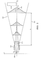
- Fig. 2 is a diagram of a velocity profile of an air stream exiting a nozzle in accordance with one embodiment
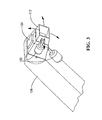
- Fig. 3 is a side view of a nozzle and a servo mechanism of a ventilation system in accordance with one embodiment
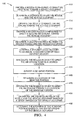
- Fig. 4 is a flow chart of a method for controlling a ventilation system in accordance with one embodiment.
- Fig. 1 illustrates a non-limiting example of a ventilation system 100 that is configured to provide an air stream 110 directed toward a vehicle occupant 114 seated in a cabin 116 of a vehicle 120.
- the ventilation system 100 may provide a heated and/or cooled air stream, such as in a heating, ventilation, and air conditioning (HVAC) system.
- HVAC heating, ventilation, and air conditioning
- the system 100 includes a nozzle 112 that is configured to direct the air stream 110 from the ventilation system 100 toward the vehicle occupant 114 seated in the cabin 116.
- a nozzle is a discrete structure configured to form and direct a stream of air that has been pressurized by an air movement device.
- the air stream 110 may be directed by articulating the entire nozzle 112.
- the air stream 110 may be directed by articulating vanes disposed within the nozzle 112.
- the nozzle 112 or vanes may be configured to be manually or automatically directed toward the vehicle occupant 114.
- the system 100 also includes a controller 122 that is configured to control a nozzle velocity of the air stream 110 and/or an effective diameter 220 of the nozzle 112 to establish a comfortable contact velocity.
- the system 100 further includes a sensor 124 configured to determine a distance 118 between the nozzle 112 and the vehicle occupant 114.
- the sensor 124 may determine data regarding the location of the vehicle occupant 114 that allows the controller 122 to determine the distance 118 between the nozzle 112 and the vehicle occupant 114.
- the sensor 124 is in communication with the controller 122.
- the system 100 may include an air plenum 126 that is configured to direct air to the nozzle 112.
- the air may be heated or cooled by a heat exchanger 128, such as an evaporator, a heater core, or a thermoelectric device included within the system 100.
- the system 100 may include a thermoelectric device that is disposed in proximity to the nozzle 112.
- the thermoelectric device may be configured to heat or cool air drawn through the system 100.
- the system 100 may further include an air movement device, such as a fan, to force air from the cabin 116 or from outside of the vehicle 120 through the nozzle 112.
- the controller 122 may control the speed of the fan to control the nozzle velocity.
- the controller 122 may control the size of an adjustable orifice or iris disposed within the nozzle 112 to control an effective diameter of the nozzle 112, thereby controlling the nozzle velocity.
- Methods and apparatus for controlling the nozzle velocity of a ventilation system 100 are well known to those skilled in the art.
- Providing the air stream 110 at a higher nozzle velocity may provide the benefit of delivering the desired heat supply rate at lower temperature (for heating) or higher temperature (for cooling) than may be required for a lower nozzle velocities. This may provide a benefit of allowing a lower operating temperature (for heating) or a higher operating temperature (for cooling) for the heat exchanger or thermoelectric device which may relax design specifications and part cost for these components.
- An air stream 110 with a higher velocity may provide a desired heat supply rate to the vehicle occupant 114 using smaller nozzles and plenums, beneficially reducing the size of the nozzle 112 and the air plenum 126, if required, and simplifying the packaging requirements for these components in the vehicle 120.
- the desired heat supply rate provides heating when it is positive in value, and supplies cooing when it is negative in value.
- the nozzle velocity may be limited by the comfortable contact velocity.
- a comfortable contact velocity is typically limited to less than 1 meter per second.
- the value of the comfortable contact velocity may vary based on a thermal sensitivity of the portion of the vehicle occupant's body that air stream 110 is contacting and whether the portion has exposed skin, e.g. the face or the portion is covered by clothing, e.g. the feet.
- the comfortable contact velocity may also be dependent on a temperature of the air stream 110.
- the maximum velocity of the air stream 110 decreases according to the distance 118 that it has travelled from the nozzle 112 of the ventilation system 100. Therefore, by determining the distance 118 between the nozzle 112 and the vehicle occupant 114, the velocity of the air stream 110 may be controlled to provide a desired contact velocity when the air stream 110 impinges on the vehicle occupant 114.
- Fig. 2 illustrates a velocity profile of an air stream 210 exiting a nozzle 212.
- the nozzle velocity 214 (U0) is the velocity of the air stream 210 as it leaves the nozzle 212.
- the contact velocity 216 (Um), is the maximum velocity of the air stream 210, typically at the center of the air stream 110, at the distance 218 (S) from the nozzle 212.
- the contact velocity 216 may be a function of the nozzle velocity 214, the effective diameter 220 (D0) of the nozzle 212, and the distance 218 from the nozzle 112.
- a desired contact velocity 216 for the air stream 210 may be provided by controlling the nozzle velocity 214 and/or the effective nozzle diameter 220 to provide the desired contact velocity 216 at the distance 218 so that it provides a comfortable contact velocity 216.
- the relationship between the nozzle velocity 214 and the contact velocity 216 as expressed in Eq. 1 assumes a free jet stream
- the equivalent diameter 220 for a nozzle 212 with a circular discharge portion is the actual diameter of the nozzle 212.
- the equivalent diameter 220 for a nozzle 212 with a shape that is other than circular is 4 times the area of the nozzle 212 divided by the perimeter of the nozzle 212, also known as the hydraulic diameter.
- the sensor 124 may be a seat location sensor 130 that is configured to determine the distance 118 between the nozzle 112 and the vehicle occupant 114 based on a seat location.
- the seat location sensor 130 may determine a seat location in the vehicle 120 by determining the location of the seat relative to a seat track of an adjustable seat, such as those typically used in a driver seat and/or front passenger seat of motor vehicles.
- the seat location sensor 130 may then communicate the seat position to the controller 122.
- the controller 122 may be configured to determine the distance 118 between the nozzle 112 and the vehicle occupant 114 based on the seat location indicated by the seat location sensor 130.
- the seat location sensor 130 may be a magnetic sensor, such as those manufactured by Allegro MicroSystems of Worchester, Massachusetts or a resistive sensor, such as those produced by CTS Automotive Products of Elkhart, Indiana.
- Seat location sensors are currently used in vehicles with inflatable restraint systems, e.g. air bag system. Therefore, utilizing the seat location sensor 130 to determine the distance 118 from the nozzle 112 to the vehicle occupant 114 may provide a cost and vehicle packaging advantage by using a common sensor for both the ventilation system 100 and the inflatable restraint system. The cost and packaging space required to provide a sensor for each system may thereby be reduced.
- the controller 122 may be configured to determine that a seat has moved from a first seat location 132 to a second seat location 134 when the seat location sensor 130 detects that the seat has changed location. The controller 122 may then determine a second distance between the nozzle 112 and the vehicle occupant 114 based on the second seat location 134. The controller 122 may then adjust the nozzle velocity and/or effective diameter 220 of the nozzle 112 to establish a comfortable contact velocity for the vehicle occupant 114 at the second seat location 134.
- the sensor 124 may be configured to determine the distance 118 between the nozzle 112 and the vehicle occupant 114 based on waves emitted from the sensor 124 and reflected from the vehicle occupant 114.
- the sensor 124 may receive the reflected waves and may determine the distance 118 between the sensor 124 based on time between emission and reception or strength of the reflected waves received be the sensor 124.
- the sensor 124 may be an ultrasonic distance sensor that utilizes the transmission and reflection of ultrasonic sound waves to determine the distance 118 between the nozzle 112 and the vehicle occupant 114.
- the sensor 124 may alternatively use the transmission and reflection of electromagnetic waves, such as infrared, visible laser light (LIDAR) or radio waves (RADAR).
- LIDAR visible laser light
- RADAR radio waves
- the sensor 124 may determine the distance 118 between the sensor 124 and the vehicle occupant 114.
- the controller 122 may then determine the distance 118 between the nozzle 112 and the vehicle occupant 114 based on a known positional relationship between the sensor 124 and the nozzle 112.
- the sensor 136 may be mounted on or near the nozzle 112 and may measure the distance 118 directly.
- the system 100 may provide a plurality of air streams 110, 138, 142, 146 directed by a plurality of nozzles 112, 140, 144, 148.
- the nozzles 112, 140, 144, 148 may be located at different distances from the vehicle occupant 114 and may be directed to different portions of the body of the vehicle occupant 114.
- the nozzle 112 may be a first nozzle 112
- the air stream 110 may be a first air stream 110
- the distance 118 may be a first distance
- the nozzle velocity may be a first nozzle velocity
- the comfortable contact velocity may be a first comfortable contact velocity.
- the system 100 may further include a second nozzle 140, 144, 148 that is configured to direct a second air stream 138, 142, 146 toward the vehicle occupant 114.
- the sensor 124 may be configured to determine a second distance between the second nozzle 140, 144, 148 and the vehicle occupant 114.
- the controller 122 may be configured to control a second nozzle velocity to establish a second comfortable contact velocity.
- the first comfortable contact velocity may be distinct from the second comfortable contact velocity.
- Fig. 3 illustrates a non-limiting example of the system 100 having a nozzle 112 including a servo mechanism 150 that is coupled to the nozzle 112 and is in communication with the controller 122.
- the servo mechanism 150 may be configured to articulate the nozzle 112 in order to direct the air stream 110 in a direction determined by the controller 122.
- articulate refers to moving the nozzle 112 in one or more axes in order to direct the air stream 110.
- the nozzle 112 may have freedom of movement in one or preferably two axes, such as when mounted in a gimbal device.
- the nozzle 112 may also be configured to move fore and aft, that is to extend and retract as well as move up/down and right/left in order to adjust the distance 118 between the nozzle 112 and the vehicle occupant 114.
- the servo mechanism 150 may include a servo motor with a ball and screw drive or a stepper motor. Alternatively, the servo mechanism may be coupled to vanes disposed within the nozzle and may move the vanes in order to direct the air stream 110 in a direction determined by the controller 122.
- the servo mechanism 150 may be configured to maintain direction of the air stream 110 to the desired location, such as a specific portion of the body of the vehicle occupant 114 rather than sweep the air stream 110 over various portions of the body of the vehicle occupant 114.
- spot conditioning means directing a stream of air at a specific temperature and flow rate toward a sensitive portion of the vehicle occupant's body to provide a heat loss rate for the sensitive portion equivalent to the heat loss rate at a comfortable temperature.
- a model of a human body identifying thermal sensation and thermal sensitivity of various body portions to temperature has been developed to determine which body portions to heat or cool to achieve thermal comfort through spot conditioning.
- the static local sensation equation by Zhang et al. ["Thermal Sensation and Comfort Models for Non-Uniform and Transient Environments: Part I: Local Sensation of Individual Body Parts", Indoor Environmental Quality (IEQ), Center for the Built Environment, Center for Environmental Design Research, University of California - Berkeley, 2009] may be used to determine the sensitivity of body portions to localized heating or cooling.
- the air stream 110 may be directed toward a sensitive portion of a body of the vehicle occupant 114 that is more sensitive to heat loss than other portions of the body.
- the controller 122 may be configured to identify the sensitive portion, determine a location of the sensitive portion, and operate the servo mechanism 150 to articulate the nozzle 112 in order to direct the air stream 110 to the location of the sensitive portion.
- the controller 122 may include a microprocessor or application specific integrated circuit (ASIC) configured to control the system 100.
- Software that configures the microprocessor or ASIC to control the system 100 may be stored in non-volatile (NV) memory within the controller 122.
- NV non-volatile
- Non-limiting examples of the types ofNV memory that may be used include electrically erasable programmable read only memory (EEPROM), masked read only memory (ROM) and flash memory.
- EEPROM electrically erasable programmable read only memory
- ROM masked read only memory
- flash memory flash memory
- the controller 122 may also include analog to digital (A/D) convertor circuits and digital to analog (D/A) convertor circuits to allow the convertor to establish electrical communication with the sensor 124, servo mechanism 150 and other electronic devices.
- A/D analog to digital
- D/A digital to analog
- the software stored within the controller 122 may also include instructions that, when executed, cause the controller 122 to identify a sensitive portion of a body of the vehicle occupant 114 that is more sensitive to heat loss, e.g. a forehead portion 152, than other portions of the body, e.g. a foot portion 172.
- the sensitive portion identified may depend whether the vehicle occupant 114 is in a high ambient temperature environment where the heat loss rate needs to be increased to maintain comfort, that is the system 100 is providing cooling of the vehicle occupant 114 or in a lower ambient temperature environment where the heat loss rate needs to be lowered in order to maintain comfort, that is the system 100 is providing heating to the vehicle occupant 114.
- the sensitive portion in a higher ambient temperature environment, e.g. greater than 24°C, may be, in order of decreasing sensitivity, a forehead portion 152, a neck portion 154, a chest portion 156, a lower arm portion 158, a face portion 160, a pelvis portion 162, an upper arm portion 164, a hand portion 166, a lower leg portion 168, a thigh portion 170, or a foot portion 172.
- a lower ambient temperature environment e.g.
- the sensitive portion may be, in order of decreasing sensitivity, a forehead portion 152, a neck portion 154, a chest portion 156, a lower arm portion 158, an upper arm portion 164, a lower leg portion 168, a foot portion 172, a pelvis portion 162, a hand portion 166, a thigh portion 170, or a face portion 160.
- the identification of sensitive body portions may be based upon models of the human body such as the Human Thermal Comfort Model developed by Zhang et al., ibid to determine thermal comfort sensitivity of body portions to the ambient temperature.
- the controller 122 may include a database of the temperature sensitivity of various body portions stored in the memory of the controller 122.
- the controller 122 may be configured to determine an ambient temperature of the vehicle cabin 116.
- the system 100 may include a temperature sensor 174 that is disposed within the vehicle cabin 116.
- the controller 122 may be in electrical communication with the temperature sensor 174.
- the controller 122 may be configured to determine a location of the sensitive portion within the vehicle cabin 116.
- the controller 122 may include a database of location information of the sensitive body portions in relation to the nozzle 112, as a non-limiting example azimuth and distance information.
- the controller 122 may utilize this location information to command the servo mechanism 150 to direct the nozzle 112 to deliver the air stream 110 to a sensitive portion of the body of the vehicle occupant 114.
- the location information may be generalized so that the location information encompasses the location of the sensitive portion of a female occupant in the 10 th percentile of height and a male occupant in the 90 th percentile of height.
- the controller 122 may be configured to determine the location of the sensitive portion based on the seat position indicated by the seat location sensor 130.
- the controller 122 may be further configured to determine a leg length of the vehicle occupant 114 based on the seat position of the vehicle occupant 114 and determine the location of the sensitive portion based on the leg length of the vehicle occupant 114.
- the controller 122 may include a database of leg length of the vehicle occupant 114 based on seat position and location information of the sensitive body portions correlated to the leg length of the vehicle occupant 114. Such a database may be generated based on anthropometric data, such as that contained in Chapter 11 of "Human Engineering Guide to Equipment Design" Harold P Van Cott and Robert G Kinkade, ed., American Institutes for Research, 1972.
- Fig. 4 illustrates steps 410 to 420 of a non-limiting method 400 of controlling a ventilation system 100 to provide an air stream 110 to a vehicle occupant 114 seated in a vehicle cabin 116.
- Step 410 PROVIDE A NOZZLE CONFIGURED TO DIRECT THE AIR STREAM, includes providing a nozzle 112 configured to direct the air stream 110 from the ventilation system 100 toward a vehicle occupant 114 seated in a vehicle cabin 116.
- Step 412 DETERMINE A DISTANCE BETWEEN THE NOZZLE AND A VEHICLE OCCUPANT, includes determining a distance 118 between the nozzle 112 and a vehicle occupant 114.
- the determination of the distance 118 between the nozzle 112 and the vehicle occupant 114 may be based on determining a location of a seat within the vehicle 120.
- the seat location may be determined by determining the location of the seat relative to an adjustable seat track.
- Step 414 OPERATE THE NOZZLE TO DIRECT THE AIR STREAM TOWARD THE VEHICLE OCCUPANT, may include operating the nozzle 112 to direct the air stream 110 toward the vehicle occupant 114.
- the air stream 110 is characterized as having a nozzle velocity effective to establish a comfortable contact velocity.
- the comfortable velocity may be delivered by controlling an exit velocity of the air stream 110 from the nozzle 112.
- the comfortable contact velocity may be delivered by controlling the effective diameter 220 of the nozzle 112.
- the comfortable contact velocity may be dependent on an air temperature of the air stream 110.
- the method 400 may include providing and controlling a plurality of nozzles 112, 140, 144, 148, therefore, the nozzle 112 may be a first nozzle 112, the air stream 110 is a first air stream 110, the distance 118 may be a first distance 118, the nozzle velocity may be a first nozzle velocity, and the comfortable contact velocity may be a first comfortable contact velocity.
- the method 400 may further include the steps 416 through 420.
- Step 416 PROVIDE A SECOND NOZZLE CONFIGURED TO DIRECT A SECOND AIR STREAM TOWARD THE VEHICLE OCCUPANT, may include providing a second nozzle 140 that is configured to direct a second air stream 138, 142, 146 from the system 100 toward the vehicle occupant 114.
- Step 418 DETERMINE A SECOND DISTANCE BETWEEN THE SECOND NOZZLE AND THE VEHICLE OCCUPANT, may include determining a second distance between the second nozzle 140, 144, 148 and the vehicle occupant 114.
- Step 420, CONTROL A SECOND NOZZLE VELOCITY TO ESTABLISH A SECOND COMFORTABLE CONTACT VELOCITY may include controlling a second nozzle velocity to establish a second comfortable contact velocity.
- the first comfortable contact velocity may be distinct from the second comfortable contact velocity.
- Fig. 5 illustrates steps 422 to 432 of the method 400 of controlling a ventilation system 100 to provide an air stream 110 to a vehicle occupant 114 seated in a vehicle cabin 116.
- Step 422 ARTICULATE THE NOZZLE IN ORDER TO DIRECT THE AIR STREAM TOWARD A DESIRED LOCATION
- the method 400 may include articulating the nozzle 112 in order to direct the air stream 110 toward a desired location within the cabin 116 of the vehicle 120.
- the desired location of Step 422 may be a sensitive portion of a body of the vehicle occupant 114 that is more sensitive to heat loss than other portions of the body.
- the method 400 may further include the steps 424 through 428.
- Step 424, IDENTIFY THE SENSITIVE PORTION may include identifying a portion of the body of the vehicle occupant 114 that is more sensitive to heat loss than other portions of the body. Identification of the sensitive portion may be based on models of the human body such as the Human Thermal Comfort Model developed by Zhang et al., ibid to determine thermal comfort sensitivity of body portions to the ambient temperature. Step 424, IDENTIFY A SENSITIVE PORTION, may be based on a database containing the temperature sensitivity of various body portions.
- Step 426 DETERMINE A LOCATION OF THE SENSITIVE PORTION, may include determining a location of the sensitive portion. The determination may be based on location information regarding the sensitive body portions in relation to the nozzle 112, as a non-limiting example azimuth and distance information. The location information may be generalized so that the location information encompasses the location of the sensitive portion of a female occupant in the 10 th percentile of height and a male occupant in the 90 th percentile of height.
- Step 428 ARTICULATE THE NOZZLE TO DIRECT THE STREAM TO THE LOCATION OF THE SENSITIVE PORTION, may include articulating the nozzle 112 to deliver the stream to the location of the sensitive portion.
- the nozzle 112 may be articulated to aim the air stream 110 toward the location of the sensitive portion, e.g. a forehead portion 152.
- the stream may be characterized as having the stream temperature and the flow rate necessary to establish the desired heat supply rate at the sensitive portion.
- the method 400 may further include the steps 430 through 432.
- Step 430 DETERMINE THE DISTANCE BETWEEN THE NOZZLE AND THE VEHICLE OCCUPANT BASED ON A SEATED HEIGHT OF THE VEHICLE OCCUPANT, may include determining the distance 118 between the nozzle 112 and the vehicle occupant 114 based on a seated height of the vehicle occupant 114. The determination the location of the seated height of the vehicle occupant may be based on the leg length of the vehicle occupant 114. Correlation between the leg length and the location of the sensitive portion may be based on anthropometric data, such as that contained in Chapter 11 of "Human Engineering Guide to Equipment Design" ibid.
- Step 432 DETERMINE THE LOCATION OF THE SENSITIVE PORTION BASED ON THE SEATED HEIGHT OF THE VEHICLE OCCUPANT, may include determining the location of the sensitive portion based on the seated height of the vehicle occupant 114. The determination may be based on location information regarding the sensitive body portions in relation to the nozzle 112, as a non-limiting example azimuth and distance information. The location information may be generalized so that the location information encompasses the location of the sensitive portion of a female occupant in the 10 th percentile of height and a male occupant in the 90 th percentile of height.
- the determination of the distance 118 between the nozzle 112 and the vehicle occupant 114 may be based on determining a location of a seat within the vehicle 120.
- the seat location may be determined by determining the location of the seat relative to an adjustable seat track and determining a leg length of the vehicle occupant based on the seat track position.
- the determination the location of the seated height of the vehicle occupant may be based on the leg length of the vehicle occupant 114.
- a ventilation system 100 and a method 400 of controlling a ventilation system that is configured to an air stream 110 directed toward a vehicle occupant 114 at a comfortable contact velocity.
- the ventilation system 100 may provide a heated or cooled air stream.
- the system 100 and method 400 determine the distance 118 between a nozzle 112 of the ventilation system 100 and the vehicle occupant 114 and control a nozzle exit velocity 214 and/or effective nozzle diameter 220 in order to provide the air stream 110 at a comfortable contact velocity 216 when the air stream 110 impinges on the vehicle occupant 114.
- the system 100 may utilize a seat location sensor 130 to determine the distance 118 between the nozzle 112 and the vehicle occupant 114. Utilizing the seat location sensor 130 to determine the distance 118 from the nozzle 112 to the vehicle occupant 114 may provide a cost and vehicle packaging advantage when the vehicle 120 uses a seat location sensor 130 with another vehicle system, e.g. an inflatable restraint system.
Landscapes
- Physics & Mathematics (AREA)
- Thermal Sciences (AREA)
- Engineering & Computer Science (AREA)
- Mechanical Engineering (AREA)
- Air-Conditioning For Vehicles (AREA)
Abstract
Description
- The present disclosure relates to a ventilation system; more specifically to a ventilation system in a vehicle configured to provide an air stream directed toward a vehicle occupant, wherein the air stream establishes a comfortable contact velocity as it impinges on the vehicle occupant.
- It may be desirable to direct an air stream from a ventilation system toward a person in order to provide comfortable heating or cooling to the person. This may be more easily implemented when the person is in a known location, such as when seated in a vehicle cabin. This directed air stream is sometimes referred to as spot conditioning. As used herein, spot conditioning means directing a stream of air at a specific temperature and flow rate toward a thermally sensitive portion of a person's body to provide a heat supply rate to the sensitive portion that is equivalent to the heat loss rate at a comfortable temperature.
- To provide a heat supply rate using a small air stream, such as an air stream typically used for spot conditioning, a higher velocity air stream may be desired to compensate for a smaller air stream volume. However, it has been observed that there is an upper limit on the velocity of the air stream contacting the person at which the person will feel comfortable, typically about 1 meter per second. Therefore, in order to provide a comfortable air stream, the air stream velocity may be controlled so that it provides the desired heat supply rate, but is limited to provide a conformable contact velocity. As used herein, the comfortable contact velocity is the maximum velocity for the air stream impinging on the body of a person at which the person would feel comfortable. It has also been observed that the velocity of an air stream varies in relation to the distance from the source of the air stream. Therefore, the distance between the air stream source and the person contacted by the air stream may need to be determined in order to provide a comfortable air stream contact velocity at the point at which the air stream contacts the person.
- In accordance with one embodiment of this invention, a ventilation system configured to provide an air stream is provided. The ventilation system includes a nozzle configured to direct the air stream toward a vehicle occupant seated in a vehicle cabin. The system also includes a controller configured to control a nozzle velocity of the air stream to establish a comfortable contact velocity. The system further includes a sensor configured to determine a distance between the nozzle and the vehicle occupant. The sensor is in communication with the controller. The system may include a plurality of nozzles configured to direct a plurality of air streams toward the vehicle occupant.
- In another embodiment of the present invention, the sensor may be configured to determine the distance between the nozzle and the vehicle occupant based on a seat location.
- In another embodiment of the present invention, the sensor may be configured to determine the distance between the nozzle and the vehicle occupant based on waves emitted from the sensor and reflected from the vehicle occupant. The waves emitted by the sensor may be ultrasonic waves or electromagnetic waves.
- In another embodiment of the present invention, the system may further include a servo mechanism that is coupled to the nozzle. The servo mechanism is in communication with the controller. The servo mechanism may be configured to articulate the nozzle in order to direct the air stream in a direction determined by the controller. The air stream may be directed toward a sensitive portion of a body of the vehicle occupant that is more sensitive to heat loss than other portions of the body. The controller may be configured to identify the sensitive portion, determine a location of the sensitive portion, and operate the servo mechanism to articulate the nozzle in order to direct the air stream to the location of the sensitive portion.
- In another embodiment of the present invention, a vehicle ventilation system is provided. The vehicle ventilation system includes a nozzle operable to direct an air stream toward a vehicle occupant seated in a vehicle cabin, a sensor configured to determine a distance between the nozzle and the vehicle occupant, and a controller configured to control a nozzle velocity of the air stream based on the distance to establish a comfortable contact velocity for the vehicle occupant.
- In yet another embodiment of the present invention, a method of controlling a ventilation system to provide an air stream is provided. The method includes the steps of providing a nozzle configured to direct the air stream, determining a distance between the nozzle and a vehicle occupant, and operating the nozzle to direct the air stream toward the vehicle occupant. The air stream is characterized as having a nozzle velocity that is effective to establish a comfortable contact velocity. The step of determining the distance between the nozzle and the vehicle occupant may be based on a seat location. The method may further include the steps of articulating the nozzle in order to direct the air stream toward a sensitive portion of a body of the vehicle occupant that is more sensitive to heat loss than other portions of the body, identifying the sensitive portion, determining a location of the sensitive portion, and articulating the nozzle in order to direct the air stream toward the location of the sensitive portion.
- Further features and advantages of the invention will appear more clearly on a reading of the following detailed description of the preferred embodiment of the invention, which is given by way of non-limiting example only and with reference to the accompanying drawings.
- The present invention will now be described, by way of example with reference to the accompanying drawings, in which:
-
Fig. 1 is a cutaway side view diagram of a vehicle equipped with a ventilation system in accordance with one embodiment; -
Fig. 2 is a diagram of a velocity profile of an air stream exiting a nozzle in accordance with one embodiment; -
Fig. 3 is a side view of a nozzle and a servo mechanism of a ventilation system in accordance with one embodiment; and -
Fig. 4 is a flow chart of a method for controlling a ventilation system in accordance with one embodiment. -
Fig. 1 illustrates a non-limiting example of aventilation system 100 that is configured to provide anair stream 110 directed toward avehicle occupant 114 seated in acabin 116 of avehicle 120. Theventilation system 100 may provide a heated and/or cooled air stream, such as in a heating, ventilation, and air conditioning (HVAC) system. Thesystem 100 includes anozzle 112 that is configured to direct theair stream 110 from theventilation system 100 toward thevehicle occupant 114 seated in thecabin 116. As used herein, a nozzle is a discrete structure configured to form and direct a stream of air that has been pressurized by an air movement device. Theair stream 110 may be directed by articulating theentire nozzle 112. Alternatively, theair stream 110 may be directed by articulating vanes disposed within thenozzle 112. Thenozzle 112 or vanes may be configured to be manually or automatically directed toward thevehicle occupant 114. Thesystem 100 also includes acontroller 122 that is configured to control a nozzle velocity of theair stream 110 and/or aneffective diameter 220 of thenozzle 112 to establish a comfortable contact velocity. Thesystem 100 further includes asensor 124 configured to determine adistance 118 between thenozzle 112 and thevehicle occupant 114. Thesensor 124 may determine data regarding the location of thevehicle occupant 114 that allows thecontroller 122 to determine thedistance 118 between thenozzle 112 and thevehicle occupant 114. Thesensor 124 is in communication with thecontroller 122. - The
system 100 may include anair plenum 126 that is configured to direct air to thenozzle 112. The air may be heated or cooled by aheat exchanger 128, such as an evaporator, a heater core, or a thermoelectric device included within thesystem 100. Alternatively, thesystem 100 may include a thermoelectric device that is disposed in proximity to thenozzle 112. The thermoelectric device may be configured to heat or cool air drawn through thesystem 100. Thesystem 100 may further include an air movement device, such as a fan, to force air from thecabin 116 or from outside of thevehicle 120 through thenozzle 112. Thecontroller 122 may control the speed of the fan to control the nozzle velocity. Alternatively, or in addition, thecontroller 122 may control the size of an adjustable orifice or iris disposed within thenozzle 112 to control an effective diameter of thenozzle 112, thereby controlling the nozzle velocity. Methods and apparatus for controlling the nozzle velocity of aventilation system 100 are well known to those skilled in the art. - Providing the
air stream 110 at a higher nozzle velocity may provide the benefit of delivering the desired heat supply rate at lower temperature (for heating) or higher temperature (for cooling) than may be required for a lower nozzle velocities. This may provide a benefit of allowing a lower operating temperature (for heating) or a higher operating temperature (for cooling) for the heat exchanger or thermoelectric device which may relax design specifications and part cost for these components. - An
air stream 110 with a higher velocity may provide a desired heat supply rate to thevehicle occupant 114 using smaller nozzles and plenums, beneficially reducing the size of thenozzle 112 and theair plenum 126, if required, and simplifying the packaging requirements for these components in thevehicle 120. As used herein, the desired heat supply rate provides heating when it is positive in value, and supplies cooing when it is negative in value. - The nozzle velocity may be limited by the comfortable contact velocity. A comfortable contact velocity is typically limited to less than 1 meter per second. However, the value of the comfortable contact velocity may vary based on a thermal sensitivity of the portion of the vehicle occupant's body that
air stream 110 is contacting and whether the portion has exposed skin, e.g. the face or the portion is covered by clothing, e.g. the feet. The comfortable contact velocity may also be dependent on a temperature of theair stream 110. The maximum velocity of theair stream 110 decreases according to thedistance 118 that it has travelled from thenozzle 112 of theventilation system 100. Therefore, by determining thedistance 118 between thenozzle 112 and thevehicle occupant 114, the velocity of theair stream 110 may be controlled to provide a desired contact velocity when theair stream 110 impinges on thevehicle occupant 114. -
Fig. 2 illustrates a velocity profile of anair stream 210 exiting anozzle 212. The nozzle velocity 214 (U0) is the velocity of theair stream 210 as it leaves thenozzle 212. The contact velocity 216 (Um), is the maximum velocity of theair stream 210, typically at the center of theair stream 110, at the distance 218 (S) from thenozzle 212. Without prescribing to any particular theory, thecontact velocity 216 may be a function of thenozzle velocity 214, the effective diameter 220 (D0) of thenozzle 212, and thedistance 218 from thenozzle 112. This relationship for a round nozzle may be expressed by the following equation, with a similar relationship for other nozzle shapes:
- Accordingly, a desired
contact velocity 216 for theair stream 210 may be provided by controlling thenozzle velocity 214 and/or theeffective nozzle diameter 220 to provide the desiredcontact velocity 216 at thedistance 218 so that it provides acomfortable contact velocity 216. The relationship between thenozzle velocity 214 and thecontact velocity 216 as expressed in Eq. 1 assumes a free jet stream - The
equivalent diameter 220 for anozzle 212 with a circular discharge portion is the actual diameter of thenozzle 212. Theequivalent diameter 220 for anozzle 212 with a shape that is other than circular is 4 times the area of thenozzle 212 divided by the perimeter of thenozzle 212, also known as the hydraulic diameter. - Referring again to
Fig. 1 , as a non-limiting example, thesensor 124 may be aseat location sensor 130 that is configured to determine thedistance 118 between thenozzle 112 and thevehicle occupant 114 based on a seat location. Theseat location sensor 130 may determine a seat location in thevehicle 120 by determining the location of the seat relative to a seat track of an adjustable seat, such as those typically used in a driver seat and/or front passenger seat of motor vehicles. Theseat location sensor 130 may then communicate the seat position to thecontroller 122. Thecontroller 122 may be configured to determine thedistance 118 between thenozzle 112 and thevehicle occupant 114 based on the seat location indicated by theseat location sensor 130. Theseat location sensor 130 may be a magnetic sensor, such as those manufactured by Allegro MicroSystems of Worchester, Massachusetts or a resistive sensor, such as those produced by CTS Automotive Products of Elkhart, Indiana. - Seat location sensors are currently used in vehicles with inflatable restraint systems, e.g. air bag system. Therefore, utilizing the
seat location sensor 130 to determine thedistance 118 from thenozzle 112 to thevehicle occupant 114 may provide a cost and vehicle packaging advantage by using a common sensor for both theventilation system 100 and the inflatable restraint system. The cost and packaging space required to provide a sensor for each system may thereby be reduced. - The
controller 122 may be configured to determine that a seat has moved from afirst seat location 132 to asecond seat location 134 when theseat location sensor 130 detects that the seat has changed location. Thecontroller 122 may then determine a second distance between thenozzle 112 and thevehicle occupant 114 based on thesecond seat location 134. Thecontroller 122 may then adjust the nozzle velocity and/oreffective diameter 220 of thenozzle 112 to establish a comfortable contact velocity for thevehicle occupant 114 at thesecond seat location 134. - As another non-limiting example, the
sensor 124 may be configured to determine thedistance 118 between thenozzle 112 and thevehicle occupant 114 based on waves emitted from thesensor 124 and reflected from thevehicle occupant 114. Thesensor 124 may receive the reflected waves and may determine thedistance 118 between thesensor 124 based on time between emission and reception or strength of the reflected waves received be thesensor 124. Thesensor 124 may be an ultrasonic distance sensor that utilizes the transmission and reflection of ultrasonic sound waves to determine thedistance 118 between thenozzle 112 and thevehicle occupant 114. Thesensor 124 may alternatively use the transmission and reflection of electromagnetic waves, such as infrared, visible laser light (LIDAR) or radio waves (RADAR). The methods and apparatuses for determining distance using ultrasonic, infrared, LIDAR and RADAR sensors are well known to those skilled in the art. - The
sensor 124 may determine thedistance 118 between thesensor 124 and thevehicle occupant 114. Thecontroller 122 may then determine thedistance 118 between thenozzle 112 and thevehicle occupant 114 based on a known positional relationship between thesensor 124 and thenozzle 112. Alternatively, thesensor 136 may be mounted on or near thenozzle 112 and may measure thedistance 118 directly. - As illustrated in
Fig. 1 , thesystem 100 may provide a plurality of air streams 110, 138, 142, 146 directed by a plurality ofnozzles nozzles vehicle occupant 114 and may be directed to different portions of the body of thevehicle occupant 114. As a non-limiting example, thenozzle 112 may be afirst nozzle 112, theair stream 110 may be afirst air stream 110, thedistance 118 may be a first distance, the nozzle velocity may be a first nozzle velocity, and the comfortable contact velocity may be a first comfortable contact velocity. Thesystem 100 may further include asecond nozzle second air stream vehicle occupant 114. Thesensor 124 may be configured to determine a second distance between thesecond nozzle vehicle occupant 114. Thecontroller 122 may be configured to control a second nozzle velocity to establish a second comfortable contact velocity. The first comfortable contact velocity may be distinct from the second comfortable contact velocity. -
Fig. 3 illustrates a non-limiting example of thesystem 100 having anozzle 112 including aservo mechanism 150 that is coupled to thenozzle 112 and is in communication with thecontroller 122. Theservo mechanism 150 may be configured to articulate thenozzle 112 in order to direct theair stream 110 in a direction determined by thecontroller 122. As used herein, articulate refers to moving thenozzle 112 in one or more axes in order to direct theair stream 110. Thenozzle 112 may have freedom of movement in one or preferably two axes, such as when mounted in a gimbal device. Thenozzle 112 may also be configured to move fore and aft, that is to extend and retract as well as move up/down and right/left in order to adjust thedistance 118 between thenozzle 112 and thevehicle occupant 114. Theservo mechanism 150 may include a servo motor with a ball and screw drive or a stepper motor. Alternatively, the servo mechanism may be coupled to vanes disposed within the nozzle and may move the vanes in order to direct theair stream 110 in a direction determined by thecontroller 122. Theservo mechanism 150 may be configured to maintain direction of theair stream 110 to the desired location, such as a specific portion of the body of thevehicle occupant 114 rather than sweep theair stream 110 over various portions of the body of thevehicle occupant 114. - It has been observed that different portions or areas of a human body have different sensitivity to heat loss caused by the ambient temperature. For example, the human face is relatively insensitive to cold ambient temperatures within a reasonable range, while other body portions, such as feet have higher sensitivity to cold ambient temperatures. Therefore, it may be advantageous to direct the
air stream 110 to portions of the vehicle occupant's body that are most thermally sensitive, as a non-limiting example for providing spot conditioning as shownU.S. Patent Application Nos. 13/442,961 ,61/479,425 61/499,312 13/442,961 61/479,425, 61/499,312 - A model of a human body identifying thermal sensation and thermal sensitivity of various body portions to temperature has been developed to determine which body portions to heat or cool to achieve thermal comfort through spot conditioning. As an illustrative example, the static local sensation equation by Zhang et al. ["Thermal Sensation and Comfort Models for Non-Uniform and Transient Environments: Part I: Local Sensation of Individual Body Parts", Indoor Environmental Quality (IEQ), Center for the Built Environment, Center for Environmental Design Research, University of California - Berkeley, 2009] may be used to determine the sensitivity of body portions to localized heating or cooling.
- As illustrated by both
Fig. 1 andFig. 3 , theair stream 110 may be directed toward a sensitive portion of a body of thevehicle occupant 114 that is more sensitive to heat loss than other portions of the body. Thecontroller 122 may be configured to identify the sensitive portion, determine a location of the sensitive portion, and operate theservo mechanism 150 to articulate thenozzle 112 in order to direct theair stream 110 to the location of the sensitive portion. - Referring again to
Fig. 1 , thecontroller 122 may include a microprocessor or application specific integrated circuit (ASIC) configured to control thesystem 100. Software that configures the microprocessor or ASIC to control thesystem 100 may be stored in non-volatile (NV) memory within thecontroller 122. Non-limiting examples of the types ofNV memory that may be used include electrically erasable programmable read only memory (EEPROM), masked read only memory (ROM) and flash memory. Thecontroller 122 may also include analog to digital (A/D) convertor circuits and digital to analog (D/A) convertor circuits to allow the convertor to establish electrical communication with thesensor 124,servo mechanism 150 and other electronic devices. - The software stored within the
controller 122 may also include instructions that, when executed, cause thecontroller 122 to identify a sensitive portion of a body of thevehicle occupant 114 that is more sensitive to heat loss, e.g. aforehead portion 152, than other portions of the body, e.g. afoot portion 172. The sensitive portion identified may depend whether thevehicle occupant 114 is in a high ambient temperature environment where the heat loss rate needs to be increased to maintain comfort, that is thesystem 100 is providing cooling of thevehicle occupant 114 or in a lower ambient temperature environment where the heat loss rate needs to be lowered in order to maintain comfort, that is thesystem 100 is providing heating to thevehicle occupant 114. - In a non-limiting example, in a higher ambient temperature environment, e.g. greater than 24°C, the sensitive portion may be, in order of decreasing sensitivity, a
forehead portion 152, aneck portion 154, achest portion 156, alower arm portion 158, aface portion 160, apelvis portion 162, anupper arm portion 164, ahand portion 166, alower leg portion 168, athigh portion 170, or afoot portion 172. In another non-limiting example, in a lower ambient temperature environment, e.g. less than 24°C, the sensitive portion may be, in order of decreasing sensitivity, aforehead portion 152, aneck portion 154, achest portion 156, alower arm portion 158, anupper arm portion 164, alower leg portion 168, afoot portion 172, apelvis portion 162, ahand portion 166, athigh portion 170, or aface portion 160. - The identification of sensitive body portions may be based upon models of the human body such as the Human Thermal Comfort Model developed by Zhang et al., ibid to determine thermal comfort sensitivity of body portions to the ambient temperature. The
controller 122 may include a database of the temperature sensitivity of various body portions stored in the memory of thecontroller 122. - The
controller 122 may be configured to determine an ambient temperature of thevehicle cabin 116. Thesystem 100 may include atemperature sensor 174 that is disposed within thevehicle cabin 116. Thecontroller 122 may be in electrical communication with thetemperature sensor 174. - The
controller 122 may be configured to determine a location of the sensitive portion within thevehicle cabin 116. Thecontroller 122 may include a database of location information of the sensitive body portions in relation to thenozzle 112, as a non-limiting example azimuth and distance information. Thecontroller 122 may utilize this location information to command theservo mechanism 150 to direct thenozzle 112 to deliver theair stream 110 to a sensitive portion of the body of thevehicle occupant 114. The location information may be generalized so that the location information encompasses the location of the sensitive portion of a female occupant in the 10th percentile of height and a male occupant in the 90th percentile of height. - The
controller 122 may be configured to determine the location of the sensitive portion based on the seat position indicated by theseat location sensor 130. Thecontroller 122 may be further configured to determine a leg length of thevehicle occupant 114 based on the seat position of thevehicle occupant 114 and determine the location of the sensitive portion based on the leg length of thevehicle occupant 114. Thecontroller 122 may include a database of leg length of thevehicle occupant 114 based on seat position and location information of the sensitive body portions correlated to the leg length of thevehicle occupant 114. Such a database may be generated based on anthropometric data, such as that contained in Chapter 11 of "Human Engineering Guide to Equipment Design" Harold P Van Cott and Robert G Kinkade, ed., American Institutes for Research, 1972. -
Fig. 4 illustratessteps 410 to 420 of anon-limiting method 400 of controlling aventilation system 100 to provide anair stream 110 to avehicle occupant 114 seated in avehicle cabin 116. -
Step 410, PROVIDE A NOZZLE CONFIGURED TO DIRECT THE AIR STREAM, includes providing anozzle 112 configured to direct theair stream 110 from theventilation system 100 toward avehicle occupant 114 seated in avehicle cabin 116. -
Step 412, DETERMINE A DISTANCE BETWEEN THE NOZZLE AND A VEHICLE OCCUPANT, includes determining adistance 118 between thenozzle 112 and avehicle occupant 114. The determination of thedistance 118 between thenozzle 112 and thevehicle occupant 114 may be based on determining a location of a seat within thevehicle 120. As a non-limiting example, the seat location may be determined by determining the location of the seat relative to an adjustable seat track. -
Step 414, OPERATE THE NOZZLE TO DIRECT THE AIR STREAM TOWARD THE VEHICLE OCCUPANT, may include operating thenozzle 112 to direct theair stream 110 toward thevehicle occupant 114. Theair stream 110 is characterized as having a nozzle velocity effective to establish a comfortable contact velocity. The comfortable velocity may be delivered by controlling an exit velocity of theair stream 110 from thenozzle 112. Alternatively, or in addition, the comfortable contact velocity may be delivered by controlling theeffective diameter 220 of thenozzle 112. The comfortable contact velocity may be dependent on an air temperature of theair stream 110. - The
method 400 may include providing and controlling a plurality ofnozzles nozzle 112 may be afirst nozzle 112, theair stream 110 is afirst air stream 110, thedistance 118 may be afirst distance 118, the nozzle velocity may be a first nozzle velocity, and the comfortable contact velocity may be a first comfortable contact velocity. Themethod 400 may further include thesteps 416 through 420. -
Step 416, PROVIDE A SECOND NOZZLE CONFIGURED TO DIRECT A SECOND AIR STREAM TOWARD THE VEHICLE OCCUPANT, may include providing asecond nozzle 140 that is configured to direct asecond air stream system 100 toward thevehicle occupant 114. -
Step 418, DETERMINE A SECOND DISTANCE BETWEEN THE SECOND NOZZLE AND THE VEHICLE OCCUPANT, may include determining a second distance between thesecond nozzle vehicle occupant 114. -
Step 420, CONTROL A SECOND NOZZLE VELOCITY TO ESTABLISH A SECOND COMFORTABLE CONTACT VELOCITY, may include controlling a second nozzle velocity to establish a second comfortable contact velocity. The first comfortable contact velocity may be distinct from the second comfortable contact velocity. - Fig. 5 illustrates
steps 422 to 432 of themethod 400 of controlling aventilation system 100 to provide anair stream 110 to avehicle occupant 114 seated in avehicle cabin 116. -
Step 422, ARTICULATE THE NOZZLE IN ORDER TO DIRECT THE AIR STREAM TOWARD A DESIRED LOCATION, themethod 400 may include articulating thenozzle 112 in order to direct theair stream 110 toward a desired location within thecabin 116 of thevehicle 120. The desired location ofStep 422 may be a sensitive portion of a body of thevehicle occupant 114 that is more sensitive to heat loss than other portions of the body. Themethod 400 may further include thesteps 424 through 428. -
Step 424, IDENTIFY THE SENSITIVE PORTION, may include identifying a portion of the body of thevehicle occupant 114 that is more sensitive to heat loss than other portions of the body. Identification of the sensitive portion may be based on models of the human body such as the Human Thermal Comfort Model developed by Zhang et al., ibid to determine thermal comfort sensitivity of body portions to the ambient temperature.Step 424, IDENTIFY A SENSITIVE PORTION, may be based on a database containing the temperature sensitivity of various body portions. -
Step 426, DETERMINE A LOCATION OF THE SENSITIVE PORTION, may include determining a location of the sensitive portion. The determination may be based on location information regarding the sensitive body portions in relation to thenozzle 112, as a non-limiting example azimuth and distance information. The location information may be generalized so that the location information encompasses the location of the sensitive portion of a female occupant in the 10th percentile of height and a male occupant in the 90th percentile of height. -
Step 428, ARTICULATE THE NOZZLE TO DIRECT THE STREAM TO THE LOCATION OF THE SENSITIVE PORTION, may include articulating thenozzle 112 to deliver the stream to the location of the sensitive portion. Thenozzle 112 may be articulated to aim theair stream 110 toward the location of the sensitive portion, e.g. aforehead portion 152. The stream may be characterized as having the stream temperature and the flow rate necessary to establish the desired heat supply rate at the sensitive portion. Themethod 400 may further include thesteps 430 through 432. -
Step 430, DETERMINE THE DISTANCE BETWEEN THE NOZZLE AND THE VEHICLE OCCUPANT BASED ON A SEATED HEIGHT OF THE VEHICLE OCCUPANT, may include determining thedistance 118 between thenozzle 112 and thevehicle occupant 114 based on a seated height of thevehicle occupant 114. The determination the location of the seated height of the vehicle occupant may be based on the leg length of thevehicle occupant 114. Correlation between the leg length and the location of the sensitive portion may be based on anthropometric data, such as that contained in Chapter 11 of "Human Engineering Guide to Equipment Design" ibid. -
Step 432, DETERMINE THE LOCATION OF THE SENSITIVE PORTION BASED ON THE SEATED HEIGHT OF THE VEHICLE OCCUPANT, may include determining the location of the sensitive portion based on the seated height of thevehicle occupant 114. The determination may be based on location information regarding the sensitive body portions in relation to thenozzle 112, as a non-limiting example azimuth and distance information. The location information may be generalized so that the location information encompasses the location of the sensitive portion of a female occupant in the 10th percentile of height and a male occupant in the 90th percentile of height. The determination of thedistance 118 between thenozzle 112 and thevehicle occupant 114 may be based on determining a location of a seat within thevehicle 120. As a non-limiting example, the seat location may be determined by determining the location of the seat relative to an adjustable seat track and determining a leg length of the vehicle occupant based on the seat track position. The determination the location of the seated height of the vehicle occupant may be based on the leg length of thevehicle occupant 114. - Accordingly, a
ventilation system 100 and amethod 400 of controlling a ventilation system that is configured to anair stream 110 directed toward avehicle occupant 114 at a comfortable contact velocity is provided. Theventilation system 100 may provide a heated or cooled air stream. Thesystem 100 andmethod 400 determine thedistance 118 between anozzle 112 of theventilation system 100 and thevehicle occupant 114 and control anozzle exit velocity 214 and/oreffective nozzle diameter 220 in order to provide theair stream 110 at acomfortable contact velocity 216 when theair stream 110 impinges on thevehicle occupant 114. Providing theair stream 110 at or near the comfortable contact velocity may provide the benefit of delivering the desired heat supply rate with asmaller nozzle 112 andsmaller air plenum 126 than may be required if lower air stream velocities are used. This may beneficially reduce the packaging requirements for thenozzle 112 and theair plenum 126 in thevehicle 120. Thesystem 100 may utilize aseat location sensor 130 to determine thedistance 118 between thenozzle 112 and thevehicle occupant 114. Utilizing theseat location sensor 130 to determine thedistance 118 from thenozzle 112 to thevehicle occupant 114 may provide a cost and vehicle packaging advantage when thevehicle 120 uses aseat location sensor 130 with another vehicle system, e.g. an inflatable restraint system. - While this invention has been described in terms of the preferred embodiments thereof, it is not intended to be so limited, but rather only to the extent set forth in the claims that follow. Moreover, the use of the terms first, second, etc. does not denote any order of importance, but rather the terms first, second, etc. are used to distinguish one element from another. Furthermore, the use of the terms a, an, etc. do not denote a limitation of quantity, but rather denote the presence of at least one of the referenced items.
Claims (15)
- A ventilation system (100) configured to provide an air stream (110), said system (100) comprising:a nozzle (112) configured to direct the air stream (110) toward a vehicle occupant (114) seated in a vehicle cabin (116);a controller (122) configured to control a nozzle velocity (214) of the air stream (110) to establish a comfortable contact velocity (216); anda sensor (124) configured to determine a distance (118) between the nozzle (112) and the vehicle occupant (114), said sensor (124) in communication with the controller (122).
- The system (100) of claim 1, wherein the sensor (124) is configured to determine the distance (118) between the nozzle (112) and the vehicle occupant (114) based on a seat location.
- System (100) as set in the preceding claim, wherein the sensor (124) is configured to determine the distance (118) between the nozzle (112) and the vehicle occupant (114) based on waves emitted from the sensor (124) and reflected from the vehicle occupant (114), wherein the waves are selected from a group consisting of ultrasonic waves and electromagnetic waves.
- System (100) as set in any of the preceding claim further including a servo mechanism (150) coupled to the nozzle (112) and in communication with the controller (122), said servo mechanism (150) configured to articulate the nozzle (112) in order to direct the air stream (110) in a direction determined by the controller (122).
- System (100) as set in claim 4, wherein the air stream (110) is directed toward a sensitive portion (152) of a body of the vehicle occupant (114) that is more sensitive to heat loss than other portions of the body, wherein the controller (122) is configured to
identify the sensitive portion (152),
determine a location of the sensitive portion (152), and
operate the servo mechanism (150) to articulate the nozzle (112) in order to direct the air stream (110) to the location of the sensitive portion (152). - System (100) as set in claim 5, wherein the sensor (124) is configured to determine the distance (118) between the nozzle (112) and the vehicle occupant (114) based on a seated height of the vehicle occupant (114) and the controller (122) is configured to determine the location of the sensitive portion (152) based on the seated height of the vehicle occupant (114).
- System (100) as set in claim 6, wherein the controller (122) includes a database of location information of the sensitive portion (152) correlated to the seated height of the vehicle occupant (114).
- System (100) as set in any of the preceding claim wherein the comfortable contact velocity (216) is dependent on a temperature of the air stream (110).
- System (100) as set in any of the preceding claim
wherein the nozzle (112) is a first nozzle (112), the air stream (110) is a first air stream (110), the distance (118) is a first distance (118), the nozzle velocity (214) is a first nozzle velocity (214), and the comfortable contact velocity (216) is a first comfortable contact velocity (216),
wherein the system (100) further includes a second nozzle (140) configured to direct a second air stream (142) toward the vehicle occupant (114),
wherein the sensor (124) is configured to determine a second distance between the second nozzle (140) and the vehicle occupant (114) and the controller (122) is configured to control a second nozzle velocity to establish a second comfortable contact velocity, and
wherein the first comfortable contact velocity (216) is distinct from the second comfortable contact velocity. - A vehicle ventilation system (100) comprising a ventilation system as set in any of the preceding claim
- A method (400) of controlling a ventilation system (100) to provide an air stream (110), said method (400) comprising the steps of:providing (410) a nozzle (112) configured to direct the air stream (110);determining (412) a distance (118) between the nozzle (112) and a vehicle occupant (114); andoperating (414) the nozzle (112) to direct the air stream (110) toward the vehicle occupant (114), wherein the air stream (110) is characterized as having a nozzle velocity (214) effective to establish a comfortable contact velocity (216) dependent on a temperature of the air stream (110).
- Method (400) as set in claim 11, wherein the step of determining (412) the distance (118) between the nozzle (112) and the vehicle occupant (114) is based on a seat location.
- Method (400) as set in claim 11 or 12,
wherein the nozzle (112) is a first nozzle (112), the air stream (110) is a first air stream (110), the distance (118) is a first distance (118), the nozzle velocity (214) is a first nozzle velocity (214), and the comfortable contact velocity (216) is a first comfortable contact velocity (216),
wherein the method (400) further includes the steps of
providing (416) a second nozzle (140) configured to direct a second air stream (138) toward the vehicle occupant (114),
determining (418) a second distance between the second nozzle (140) and the vehicle occupant (114),
controlling (420) a second nozzle velocity to establish a second comfortable contact velocity, and
wherein the first comfortable contact velocity (216) is distinct from the second comfortable contact velocity (216). - Method (400) as set in claim 11 to 13, further including a step of articulating (422) the nozzle (112) in order to direct the air stream (110) toward a desired location, the desired location being a sensitive portion (152) of a body of the vehicle occupant (114) that is more sensitive to heat loss than other portions of the body, wherein the method (400) further includes the steps of
identifying (424) the sensitive portion (152),
determining (426) a location of the sensitive portion (152), and
articulating (428) the nozzle (112) in order to direct the air stream (110) determining (430) the distance (118) between the nozzle (112) and the vehicle occupant (114) based on a seated height of the vehicle occupant (114); and
determining (432) the location of the sensitive portion (152) based on the seated height of the vehicle occupant (114). - Method (400) as set in claim 14, wherein the step of determining (426) the location of the sensitive portion (152) is further based on a seat location.
Applications Claiming Priority (1)
| Application Number | Priority Date | Filing Date | Title |
|---|---|---|---|
| US13/528,968 US9409461B2 (en) | 2012-06-21 | 2012-06-21 | Air stream velocity control for ventilation system |
Publications (2)
| Publication Number | Publication Date |
|---|---|
| EP2676822A1 true EP2676822A1 (en) | 2013-12-25 |
| EP2676822B1 EP2676822B1 (en) | 2018-04-25 |
Family
ID=48790171
Family Applications (1)
| Application Number | Title | Priority Date | Filing Date |
|---|---|---|---|
| EP13173101.0A Not-in-force EP2676822B1 (en) | 2012-06-21 | 2013-06-20 | Air stream velocity control for ventilation system |
Country Status (3)
| Country | Link |
|---|---|
| US (1) | US9409461B2 (en) |
| EP (1) | EP2676822B1 (en) |
| CN (1) | CN203460662U (en) |
Cited By (3)
| Publication number | Priority date | Publication date | Assignee | Title |
|---|---|---|---|---|
| GB2579547A (en) * | 2018-11-30 | 2020-07-01 | Jaguar Land Rover Ltd | A vehicle system |
| WO2021175840A1 (en) * | 2020-03-03 | 2021-09-10 | Kautex Textron Gmbh & Co. Kg | Headliner system for a motor vehicle |
| EP3887730A4 (en) * | 2018-11-27 | 2022-02-23 | Scott Bradley Baker | Air vent assembly and control system |
Families Citing this family (13)
| Publication number | Priority date | Publication date | Assignee | Title |
|---|---|---|---|---|
| US9469176B2 (en) * | 2015-01-08 | 2016-10-18 | Delphi Technologies, Inc. | System and method to detect an unattended occupant in a vehicle and take safety countermeasures |
| DE102015220739A1 (en) * | 2015-10-23 | 2017-04-27 | Bayerische Motoren Werke Aktiengesellschaft | Arrangement and method for introducing air into a passenger compartment of a vehicle |
| US10464397B2 (en) * | 2016-03-03 | 2019-11-05 | Tesla, Inc. | Thermal system with high aspect ratio vent |
| US10752082B1 (en) * | 2016-05-26 | 2020-08-25 | Apple Inc. | Climate control system with slit-vent fluid delivery |
| WO2018016196A1 (en) * | 2016-07-19 | 2018-01-25 | 株式会社デンソー | Vehicle air-conditioning apparatus |
| JP6702295B2 (en) * | 2017-02-14 | 2020-06-03 | 株式会社デンソー | Vehicle air conditioning unit |
| DE102017203334A1 (en) * | 2017-03-01 | 2018-09-06 | Bayerische Motoren Werke Aktiengesellschaft | Air vents for a motor vehicle |
| US10252688B2 (en) * | 2017-03-22 | 2019-04-09 | Ford Global Technologies, Llc | Monitoring a vehicle cabin |
| KR102536615B1 (en) | 2018-06-11 | 2023-05-25 | 한온시스템 주식회사 | Air conditioner for vehicle |
| CN109720167B (en) * | 2018-12-29 | 2022-01-18 | 曼德电子电器有限公司 | Vehicle air conditioner control system and method |
| CN111731074B (en) * | 2020-06-30 | 2022-03-04 | 东风汽车有限公司 | Automobile air port adjusting method and electronic equipment |
| US12377709B2 (en) * | 2022-04-12 | 2025-08-05 | Rivian Ip Holdings, Llc | Automatic orientation of hvac air vents to occupant |
| US12515497B2 (en) * | 2022-12-23 | 2026-01-06 | Rivian Ip Holdings, Llc | Integrated converging ventilization system |
Citations (4)
| Publication number | Priority date | Publication date | Assignee | Title |
|---|---|---|---|---|
| EP1070626A2 (en) * | 1999-07-19 | 2001-01-24 | Volkswagen Aktiengesellschaft | Arrangement and method for individually and automatically adjusting the function of elements of cars |
| US20080256967A1 (en) * | 2007-04-20 | 2008-10-23 | Honda Motor Co., Ltd. | Fitness factor for automatically adjusting a vehicle hvac system |
| DE102008018397A1 (en) * | 2008-04-10 | 2009-10-15 | Volkswagen Ag | Method for regulating air conditioning of interior of motor vehicle, involves determining state information of body part of passenger of motor vehicle |
| EP2305499A1 (en) * | 2009-09-30 | 2011-04-06 | Panasonic Electric Works Co., Ltd. | Electrostatic atomizer for use in a motor vehicle |
Family Cites Families (12)
| Publication number | Priority date | Publication date | Assignee | Title |
|---|---|---|---|---|
| US2191208A (en) * | 1932-12-24 | 1940-02-20 | Gen Motors Corp | Air conditioning |
| US5172865A (en) * | 1989-01-12 | 1992-12-22 | Toyota Jidosha Kabushiki Kaisha | Fuel supply device of an engine |
| JP3055923B2 (en) * | 1990-08-24 | 2000-06-26 | 株式会社豊田中央研究所 | Control device for air conditioner |
| US5145112A (en) * | 1990-10-08 | 1992-09-08 | Kabushiki Kaisha Toyota Chuo Kenkyusho | Air conditioner |
| US5400963A (en) | 1991-07-10 | 1995-03-28 | Naldec Corporation | Method and apparatus for controlling vehicle air conditioner |
| JPH05193338A (en) | 1991-10-16 | 1993-08-03 | Toyota Central Res & Dev Lab Inc | Air conditioning controller |
| US5180333A (en) * | 1991-10-28 | 1993-01-19 | Norm Pacific Automation Corp. | Ventilation device adjusted and controlled automatically with movement of human body |
| US5449275A (en) | 1993-05-11 | 1995-09-12 | Gluszek; Andrzej | Controller and method for operation of electric fan |
| US5573269A (en) * | 1993-12-02 | 1996-11-12 | Trw Vehicle Safety Systems Inc. | Apparatus and method for sensing and restraining an occupant of a vehicle seat |
| US6454178B1 (en) * | 2001-05-24 | 2002-09-24 | Ford Global Technologies, Inc. | Adaptive controller for an automotive HVAC system |
| DE10308413A1 (en) * | 2003-02-27 | 2004-09-16 | Bayerische Motoren Werke Ag | Method of control for motor vehicle heating and air conditioning installation has position of air conditioning flaps and seating position used to determine optimum settings for occupants |
| US20080248736A1 (en) * | 2007-04-03 | 2008-10-09 | Denso Corporation | Air conditioner for vehicle |
-
2012
- 2012-06-21 US US13/528,968 patent/US9409461B2/en not_active Expired - Fee Related
-
2013
- 2013-06-20 EP EP13173101.0A patent/EP2676822B1/en not_active Not-in-force
- 2013-06-21 CN CN201320362839.0U patent/CN203460662U/en not_active Expired - Fee Related
Patent Citations (4)
| Publication number | Priority date | Publication date | Assignee | Title |
|---|---|---|---|---|
| EP1070626A2 (en) * | 1999-07-19 | 2001-01-24 | Volkswagen Aktiengesellschaft | Arrangement and method for individually and automatically adjusting the function of elements of cars |
| US20080256967A1 (en) * | 2007-04-20 | 2008-10-23 | Honda Motor Co., Ltd. | Fitness factor for automatically adjusting a vehicle hvac system |
| DE102008018397A1 (en) * | 2008-04-10 | 2009-10-15 | Volkswagen Ag | Method for regulating air conditioning of interior of motor vehicle, involves determining state information of body part of passenger of motor vehicle |
| EP2305499A1 (en) * | 2009-09-30 | 2011-04-06 | Panasonic Electric Works Co., Ltd. | Electrostatic atomizer for use in a motor vehicle |
Non-Patent Citations (2)
| Title |
|---|
| HAROLD P VAN COTT AND ROBERT G KINKADE: "Human Engineering Guide to Equipment Design", 1972, AMERICAN INSTITUTES FOR RESEARCH |
| ZHANG ET AL.: "Thermal Sensation and Comfort Models for Non-Uniform and Transient Environments: Part I: Local Sensation of Individual Body Parts", INDOOR ENVIRONMENTAL QUALITY (IEQ), CENTER FOR THE BUILT ENVIRONMENT, CENTER FOR ENVIRONMENTAL DESIGN RESEARCH, 2009 |
Cited By (4)
| Publication number | Priority date | Publication date | Assignee | Title |
|---|---|---|---|---|
| EP3887730A4 (en) * | 2018-11-27 | 2022-02-23 | Scott Bradley Baker | Air vent assembly and control system |
| GB2579547A (en) * | 2018-11-30 | 2020-07-01 | Jaguar Land Rover Ltd | A vehicle system |
| WO2021175840A1 (en) * | 2020-03-03 | 2021-09-10 | Kautex Textron Gmbh & Co. Kg | Headliner system for a motor vehicle |
| US11760166B2 (en) | 2020-03-03 | 2023-09-19 | Kautex Textron Gmbh & Co. Kg | Headliner system for a motor vehicle |
Also Published As
| Publication number | Publication date |
|---|---|
| CN203460662U (en) | 2014-03-05 |
| US20130344791A1 (en) | 2013-12-26 |
| EP2676822B1 (en) | 2018-04-25 |
| US9409461B2 (en) | 2016-08-09 |
Similar Documents
| Publication | Publication Date | Title |
|---|---|---|
| EP2676822B1 (en) | Air stream velocity control for ventilation system | |
| KR101978511B1 (en) | System and method of providing quick thermal comfort with reduced energy by using directed spot conditioning | |
| JP7159462B2 (en) | Heat control method for heat control device especially for passenger compartment | |
| CN110962540A (en) | Vehicle-mounted air conditioner control method and related device | |
| EP2121360B1 (en) | Method and system which affects the psychophysical state of a user | |
| US10926605B2 (en) | Wearable monitor for personal thermal control in a vehicle | |
| US10723198B2 (en) | Ventilation system and ventilation method for a motor vehicle | |
| EP2719560B1 (en) | Heating and cooling system for occupants of the rear portion of a vehicle | |
| TR201511752A2 (en) | INFRARED TARGETED GUIDED AIR CONDITIONING CONTROL SYSTEM | |
| EP3666564B1 (en) | A system and method for estimating climate needs | |
| JPH1067218A (en) | Air conditioner for traveling vehicles with air guide device adjustable in relation to solar radiation | |
| JP7250915B2 (en) | Automotive ventilator, thermal management device, and method of using such an automotive ventilator | |
| US20190184788A1 (en) | Method and system of controlling climate controlled zones in a vehicle based on occupant presence | |
| JP3952852B2 (en) | Air conditioning system | |
| EP3994540A1 (en) | A wireless system and method to generate a thermal comfort map of a vehicle. | |
| CN110679134A (en) | Control system for moving body | |
| KR20160134223A (en) | Air conditioning system for vehicle | |
| GB2344647A (en) | A vehicle climate control arrangement | |
| JPH03156239A (en) | Air conditioner | |
| CN111731075A (en) | Method for adjusting directional air opening of automobile air conditioner and electronic equipment | |
| JP2004359130A (en) | Air conditioner for vehicle | |
| JP2024504738A (en) | thermal systems for vehicles | |
| CN114714858A (en) | Air conditioning system for vehicle, control method thereof and vehicle | |
| JPS6374709A (en) | Air-conditioner for vehicle | |
| CN119610992B (en) | A method, system and vehicle for controlling temperature in the passenger compartment |
Legal Events
| Date | Code | Title | Description |
|---|---|---|---|
| PUAI | Public reference made under article 153(3) epc to a published international application that has entered the european phase |
Free format text: ORIGINAL CODE: 0009012 |
|
| AK | Designated contracting states |
Kind code of ref document: A1 Designated state(s): AL AT BE BG CH CY CZ DE DK EE ES FI FR GB GR HR HU IE IS IT LI LT LU LV MC MK MT NL NO PL PT RO RS SE SI SK SM TR |
|
| AX | Request for extension of the european patent |
Extension state: BA ME |
|
| 17P | Request for examination filed |
Effective date: 20140625 |
|
| RBV | Designated contracting states (corrected) |
Designated state(s): AL AT BE BG CH CY CZ DE DK EE ES FI FR GB GR HR HU IE IS IT LI LT LU LV MC MK MT NL NO PL PT RO RS SE SI SK SM TR |
|
| 17Q | First examination report despatched |
Effective date: 20141211 |
|
| RAP1 | Party data changed (applicant data changed or rights of an application transferred) |
Owner name: MAHLE INTERNATIONAL GMBH |
|
| GRAP | Despatch of communication of intention to grant a patent |
Free format text: ORIGINAL CODE: EPIDOSNIGR1 |
|
| INTG | Intention to grant announced |
Effective date: 20180116 |
|
| GRAA | (expected) grant |
Free format text: ORIGINAL CODE: 0009210 |
|
| GRAS | Grant fee paid |
Free format text: ORIGINAL CODE: EPIDOSNIGR3 |
|
| AK | Designated contracting states |
Kind code of ref document: B1 Designated state(s): AL AT BE BG CH CY CZ DE DK EE ES FI FR GB GR HR HU IE IS IT LI LT LU LV MC MK MT NL NO PL PT RO RS SE SI SK SM TR |
|
| REG | Reference to a national code |
Ref country code: GB Ref legal event code: FG4D |
|
| REG | Reference to a national code |
Ref country code: CH Ref legal event code: EP |
|
| REG | Reference to a national code |
Ref country code: AT Ref legal event code: REF Ref document number: 992473 Country of ref document: AT Kind code of ref document: T Effective date: 20180515 |
|
| REG | Reference to a national code |
Ref country code: IE Ref legal event code: FG4D |
|
| REG | Reference to a national code |
Ref country code: DE Ref legal event code: R096 Ref document number: 602013036357 Country of ref document: DE |
|
| REG | Reference to a national code |
Ref country code: NL Ref legal event code: MP Effective date: 20180425 |
|
| REG | Reference to a national code |
Ref country code: LT Ref legal event code: MG4D |
|
| PG25 | Lapsed in a contracting state [announced via postgrant information from national office to epo] |
Ref country code: NL Free format text: LAPSE BECAUSE OF FAILURE TO SUBMIT A TRANSLATION OF THE DESCRIPTION OR TO PAY THE FEE WITHIN THE PRESCRIBED TIME-LIMIT Effective date: 20180425 |
|
| PG25 | Lapsed in a contracting state [announced via postgrant information from national office to epo] |
Ref country code: NO Free format text: LAPSE BECAUSE OF FAILURE TO SUBMIT A TRANSLATION OF THE DESCRIPTION OR TO PAY THE FEE WITHIN THE PRESCRIBED TIME-LIMIT Effective date: 20180725 Ref country code: FI Free format text: LAPSE BECAUSE OF FAILURE TO SUBMIT A TRANSLATION OF THE DESCRIPTION OR TO PAY THE FEE WITHIN THE PRESCRIBED TIME-LIMIT Effective date: 20180425 Ref country code: BG Free format text: LAPSE BECAUSE OF FAILURE TO SUBMIT A TRANSLATION OF THE DESCRIPTION OR TO PAY THE FEE WITHIN THE PRESCRIBED TIME-LIMIT Effective date: 20180725 Ref country code: ES Free format text: LAPSE BECAUSE OF FAILURE TO SUBMIT A TRANSLATION OF THE DESCRIPTION OR TO PAY THE FEE WITHIN THE PRESCRIBED TIME-LIMIT Effective date: 20180425 Ref country code: SE Free format text: LAPSE BECAUSE OF FAILURE TO SUBMIT A TRANSLATION OF THE DESCRIPTION OR TO PAY THE FEE WITHIN THE PRESCRIBED TIME-LIMIT Effective date: 20180425 Ref country code: LT Free format text: LAPSE BECAUSE OF FAILURE TO SUBMIT A TRANSLATION OF THE DESCRIPTION OR TO PAY THE FEE WITHIN THE PRESCRIBED TIME-LIMIT Effective date: 20180425 Ref country code: PL Free format text: LAPSE BECAUSE OF FAILURE TO SUBMIT A TRANSLATION OF THE DESCRIPTION OR TO PAY THE FEE WITHIN THE PRESCRIBED TIME-LIMIT Effective date: 20180425 |
|
| PG25 | Lapsed in a contracting state [announced via postgrant information from national office to epo] |
Ref country code: LV Free format text: LAPSE BECAUSE OF FAILURE TO SUBMIT A TRANSLATION OF THE DESCRIPTION OR TO PAY THE FEE WITHIN THE PRESCRIBED TIME-LIMIT Effective date: 20180425 Ref country code: GR Free format text: LAPSE BECAUSE OF FAILURE TO SUBMIT A TRANSLATION OF THE DESCRIPTION OR TO PAY THE FEE WITHIN THE PRESCRIBED TIME-LIMIT Effective date: 20180726 Ref country code: HR Free format text: LAPSE BECAUSE OF FAILURE TO SUBMIT A TRANSLATION OF THE DESCRIPTION OR TO PAY THE FEE WITHIN THE PRESCRIBED TIME-LIMIT Effective date: 20180425 Ref country code: RS Free format text: LAPSE BECAUSE OF FAILURE TO SUBMIT A TRANSLATION OF THE DESCRIPTION OR TO PAY THE FEE WITHIN THE PRESCRIBED TIME-LIMIT Effective date: 20180425 |
|
| REG | Reference to a national code |
Ref country code: AT Ref legal event code: MK05 Ref document number: 992473 Country of ref document: AT Kind code of ref document: T Effective date: 20180425 |
|
| PG25 | Lapsed in a contracting state [announced via postgrant information from national office to epo] |
Ref country code: PT Free format text: LAPSE BECAUSE OF FAILURE TO SUBMIT A TRANSLATION OF THE DESCRIPTION OR TO PAY THE FEE WITHIN THE PRESCRIBED TIME-LIMIT Effective date: 20180827 |
|
| REG | Reference to a national code |
Ref country code: DE Ref legal event code: R097 Ref document number: 602013036357 Country of ref document: DE |
|
| PG25 | Lapsed in a contracting state [announced via postgrant information from national office to epo] |
Ref country code: DK Free format text: LAPSE BECAUSE OF FAILURE TO SUBMIT A TRANSLATION OF THE DESCRIPTION OR TO PAY THE FEE WITHIN THE PRESCRIBED TIME-LIMIT Effective date: 20180425 Ref country code: EE Free format text: LAPSE BECAUSE OF FAILURE TO SUBMIT A TRANSLATION OF THE DESCRIPTION OR TO PAY THE FEE WITHIN THE PRESCRIBED TIME-LIMIT Effective date: 20180425 Ref country code: AT Free format text: LAPSE BECAUSE OF FAILURE TO SUBMIT A TRANSLATION OF THE DESCRIPTION OR TO PAY THE FEE WITHIN THE PRESCRIBED TIME-LIMIT Effective date: 20180425 Ref country code: RO Free format text: LAPSE BECAUSE OF FAILURE TO SUBMIT A TRANSLATION OF THE DESCRIPTION OR TO PAY THE FEE WITHIN THE PRESCRIBED TIME-LIMIT Effective date: 20180425 Ref country code: CZ Free format text: LAPSE BECAUSE OF FAILURE TO SUBMIT A TRANSLATION OF THE DESCRIPTION OR TO PAY THE FEE WITHIN THE PRESCRIBED TIME-LIMIT Effective date: 20180425 Ref country code: SK Free format text: LAPSE BECAUSE OF FAILURE TO SUBMIT A TRANSLATION OF THE DESCRIPTION OR TO PAY THE FEE WITHIN THE PRESCRIBED TIME-LIMIT Effective date: 20180425 |
|
| REG | Reference to a national code |
Ref country code: CH Ref legal event code: PL |
|
| PG25 | Lapsed in a contracting state [announced via postgrant information from national office to epo] |
Ref country code: SM Free format text: LAPSE BECAUSE OF FAILURE TO SUBMIT A TRANSLATION OF THE DESCRIPTION OR TO PAY THE FEE WITHIN THE PRESCRIBED TIME-LIMIT Effective date: 20180425 Ref country code: IT Free format text: LAPSE BECAUSE OF FAILURE TO SUBMIT A TRANSLATION OF THE DESCRIPTION OR TO PAY THE FEE WITHIN THE PRESCRIBED TIME-LIMIT Effective date: 20180425 |
|
| PLBE | No opposition filed within time limit |
Free format text: ORIGINAL CODE: 0009261 |
|
| STAA | Information on the status of an ep patent application or granted ep patent |
Free format text: STATUS: NO OPPOSITION FILED WITHIN TIME LIMIT |
|
| REG | Reference to a national code |
Ref country code: BE Ref legal event code: MM Effective date: 20180630 |
|
| REG | Reference to a national code |
Ref country code: IE Ref legal event code: MM4A |
|
| GBPC | Gb: european patent ceased through non-payment of renewal fee |
Effective date: 20180725 |
|
| PG25 | Lapsed in a contracting state [announced via postgrant information from national office to epo] |
Ref country code: MC Free format text: LAPSE BECAUSE OF FAILURE TO SUBMIT A TRANSLATION OF THE DESCRIPTION OR TO PAY THE FEE WITHIN THE PRESCRIBED TIME-LIMIT Effective date: 20180425 Ref country code: LU Free format text: LAPSE BECAUSE OF NON-PAYMENT OF DUE FEES Effective date: 20180620 |
|
| 26N | No opposition filed |
Effective date: 20190128 |
|
| PG25 | Lapsed in a contracting state [announced via postgrant information from national office to epo] |
Ref country code: GB Free format text: LAPSE BECAUSE OF NON-PAYMENT OF DUE FEES Effective date: 20180725 Ref country code: LI Free format text: LAPSE BECAUSE OF NON-PAYMENT OF DUE FEES Effective date: 20180630 Ref country code: CH Free format text: LAPSE BECAUSE OF NON-PAYMENT OF DUE FEES Effective date: 20180630 Ref country code: FR Free format text: LAPSE BECAUSE OF NON-PAYMENT OF DUE FEES Effective date: 20180625 Ref country code: IE Free format text: LAPSE BECAUSE OF NON-PAYMENT OF DUE FEES Effective date: 20180620 |
|
| PG25 | Lapsed in a contracting state [announced via postgrant information from national office to epo] |
Ref country code: SI Free format text: LAPSE BECAUSE OF FAILURE TO SUBMIT A TRANSLATION OF THE DESCRIPTION OR TO PAY THE FEE WITHIN THE PRESCRIBED TIME-LIMIT Effective date: 20180425 Ref country code: BE Free format text: LAPSE BECAUSE OF NON-PAYMENT OF DUE FEES Effective date: 20180630 |
|
| PG25 | Lapsed in a contracting state [announced via postgrant information from national office to epo] |
Ref country code: AL Free format text: LAPSE BECAUSE OF FAILURE TO SUBMIT A TRANSLATION OF THE DESCRIPTION OR TO PAY THE FEE WITHIN THE PRESCRIBED TIME-LIMIT Effective date: 20180425 |
|
| PG25 | Lapsed in a contracting state [announced via postgrant information from national office to epo] |
Ref country code: MT Free format text: LAPSE BECAUSE OF NON-PAYMENT OF DUE FEES Effective date: 20180620 |
|
| PG25 | Lapsed in a contracting state [announced via postgrant information from national office to epo] |
Ref country code: TR Free format text: LAPSE BECAUSE OF FAILURE TO SUBMIT A TRANSLATION OF THE DESCRIPTION OR TO PAY THE FEE WITHIN THE PRESCRIBED TIME-LIMIT Effective date: 20180425 |
|
| PG25 | Lapsed in a contracting state [announced via postgrant information from national office to epo] |
Ref country code: HU Free format text: LAPSE BECAUSE OF FAILURE TO SUBMIT A TRANSLATION OF THE DESCRIPTION OR TO PAY THE FEE WITHIN THE PRESCRIBED TIME-LIMIT; INVALID AB INITIO Effective date: 20130620 |
|
| PG25 | Lapsed in a contracting state [announced via postgrant information from national office to epo] |
Ref country code: MK Free format text: LAPSE BECAUSE OF NON-PAYMENT OF DUE FEES Effective date: 20180425 Ref country code: CY Free format text: LAPSE BECAUSE OF FAILURE TO SUBMIT A TRANSLATION OF THE DESCRIPTION OR TO PAY THE FEE WITHIN THE PRESCRIBED TIME-LIMIT Effective date: 20180425 |
|
| PG25 | Lapsed in a contracting state [announced via postgrant information from national office to epo] |
Ref country code: IS Free format text: LAPSE BECAUSE OF FAILURE TO SUBMIT A TRANSLATION OF THE DESCRIPTION OR TO PAY THE FEE WITHIN THE PRESCRIBED TIME-LIMIT Effective date: 20180825 |
|
| PGFP | Annual fee paid to national office [announced via postgrant information from national office to epo] |
Ref country code: DE Payment date: 20200827 Year of fee payment: 8 |
|
| REG | Reference to a national code |
Ref country code: DE Ref legal event code: R119 Ref document number: 602013036357 Country of ref document: DE |
|
| PG25 | Lapsed in a contracting state [announced via postgrant information from national office to epo] |
Ref country code: DE Free format text: LAPSE BECAUSE OF NON-PAYMENT OF DUE FEES Effective date: 20220101 |