EP2676779B2 - Internal mixer - Google Patents
Internal mixer Download PDFInfo
- Publication number
- EP2676779B2 EP2676779B2 EP11858598.3A EP11858598A EP2676779B2 EP 2676779 B2 EP2676779 B2 EP 2676779B2 EP 11858598 A EP11858598 A EP 11858598A EP 2676779 B2 EP2676779 B2 EP 2676779B2
- Authority
- EP
- European Patent Office
- Prior art keywords
- connecting beam
- connection portion
- cylinder
- rod member
- rod
- Prior art date
- Legal status (The legal status is an assumption and is not a legal conclusion. Google has not performed a legal analysis and makes no representation as to the accuracy of the status listed.)
- Not-in-force
Links
Images


Classifications
-
- B—PERFORMING OPERATIONS; TRANSPORTING
- B29—WORKING OF PLASTICS; WORKING OF SUBSTANCES IN A PLASTIC STATE IN GENERAL
- B29B—PREPARATION OR PRETREATMENT OF THE MATERIAL TO BE SHAPED; MAKING GRANULES OR PREFORMS; RECOVERY OF PLASTICS OR OTHER CONSTITUENTS OF WASTE MATERIAL CONTAINING PLASTICS
- B29B7/00—Mixing; Kneading
- B29B7/02—Mixing; Kneading non-continuous, with mechanical mixing or kneading devices, i.e. batch type
- B29B7/22—Component parts, details or accessories; Auxiliary operations
- B29B7/24—Component parts, details or accessories; Auxiliary operations for feeding
-
- B—PERFORMING OPERATIONS; TRANSPORTING
- B29—WORKING OF PLASTICS; WORKING OF SUBSTANCES IN A PLASTIC STATE IN GENERAL
- B29B—PREPARATION OR PRETREATMENT OF THE MATERIAL TO BE SHAPED; MAKING GRANULES OR PREFORMS; RECOVERY OF PLASTICS OR OTHER CONSTITUENTS OF WASTE MATERIAL CONTAINING PLASTICS
- B29B7/00—Mixing; Kneading
- B29B7/02—Mixing; Kneading non-continuous, with mechanical mixing or kneading devices, i.e. batch type
- B29B7/06—Mixing; Kneading non-continuous, with mechanical mixing or kneading devices, i.e. batch type with movable mixing or kneading devices
- B29B7/10—Mixing; Kneading non-continuous, with mechanical mixing or kneading devices, i.e. batch type with movable mixing or kneading devices rotary
- B29B7/18—Mixing; Kneading non-continuous, with mechanical mixing or kneading devices, i.e. batch type with movable mixing or kneading devices rotary with more than one shaft
- B29B7/183—Mixing; Kneading non-continuous, with mechanical mixing or kneading devices, i.e. batch type with movable mixing or kneading devices rotary with more than one shaft having a casing closely surrounding the rotors, e.g. of Banbury type
-
- B—PERFORMING OPERATIONS; TRANSPORTING
- B29—WORKING OF PLASTICS; WORKING OF SUBSTANCES IN A PLASTIC STATE IN GENERAL
- B29B—PREPARATION OR PRETREATMENT OF THE MATERIAL TO BE SHAPED; MAKING GRANULES OR PREFORMS; RECOVERY OF PLASTICS OR OTHER CONSTITUENTS OF WASTE MATERIAL CONTAINING PLASTICS
- B29B7/00—Mixing; Kneading
- B29B7/02—Mixing; Kneading non-continuous, with mechanical mixing or kneading devices, i.e. batch type
- B29B7/22—Component parts, details or accessories; Auxiliary operations
- B29B7/24—Component parts, details or accessories; Auxiliary operations for feeding
- B29B7/248—Component parts, details or accessories; Auxiliary operations for feeding with plungers for introducing the material, e.g. from below
-
- B—PERFORMING OPERATIONS; TRANSPORTING
- B29—WORKING OF PLASTICS; WORKING OF SUBSTANCES IN A PLASTIC STATE IN GENERAL
- B29B—PREPARATION OR PRETREATMENT OF THE MATERIAL TO BE SHAPED; MAKING GRANULES OR PREFORMS; RECOVERY OF PLASTICS OR OTHER CONSTITUENTS OF WASTE MATERIAL CONTAINING PLASTICS
- B29B7/00—Mixing; Kneading
- B29B7/74—Mixing; Kneading using other mixers or combinations of mixers, e.g. of dissimilar mixers ; Plant
- B29B7/7476—Systems, i.e. flow charts or diagrams; Plants
- B29B7/7495—Systems, i.e. flow charts or diagrams; Plants for mixing rubber
-
- F—MECHANICAL ENGINEERING; LIGHTING; HEATING; WEAPONS; BLASTING
- F15—FLUID-PRESSURE ACTUATORS; HYDRAULICS OR PNEUMATICS IN GENERAL
- F15B—SYSTEMS ACTING BY MEANS OF FLUIDS IN GENERAL; FLUID-PRESSURE ACTUATORS, e.g. SERVOMOTORS; DETAILS OF FLUID-PRESSURE SYSTEMS, NOT OTHERWISE PROVIDED FOR
- F15B15/00—Fluid-actuated devices for displacing a member from one position to another; Gearing associated therewith
- F15B15/02—Mechanical layout characterised by the means for converting the movement of the fluid-actuated element into movement of the finally-operated member
- F15B15/04—Mechanical layout characterised by the means for converting the movement of the fluid-actuated element into movement of the finally-operated member with oscillating cylinder
Definitions
- the present invention relates to an internal mixer in which rotors mix and knead a material in a mixing chamber and a floating weight pushes down the material during mixing and kneading the material.
- An internal mixer has a mixing chamber having rotors incorporated in a hopper (body), and mixes and kneads a material in the mixing chamber.
- a material to be mixed and kneaded is a raw material used for various rubber products such as a tire for an automobile.
- the internal mixer is provided with a floating weight for pushing down the material in the mixing chamber during mixing and kneading the material. The floating weight moves upward and downward by activation of hydraulic cylinders.
- Each hydraulic cylinder is connected at its head to the hopper and connected at its rod to a connecting beam.
- the connecting beam is a horizontal member disposed above the hopper and extending in a direction substantially perpendicular to the upward and downward direction.
- a rod member whose lower end is fixed to the floating weight is connected to the connecting beam. The hydraulic cylinders are activated so as to move the floating weight upward and downward along with the upward and downward movement of the connecting beam and the rod member.
- JP 3474725 B discloses a technique to secure a smooth upward and downward movement of a floating weight, and to prevent abnormal abrasion of a guide member for guiding a rod member.
- the guide member is a member attached to a hopper top surface.
- US 4877328 A discloses an internal mixer with a mixing chamber and hydraulic cylinders that are symmetrically disposed about a charging hopper.
- a floating weight is driven via a movable crosspiece and a shaft.
- the floating weight is connected to the shaft and the upper end of the shaft is secured in the crosspiece such that the shaft is apparently inserted through a through hole in the crosspiece and is retained by an expanded head at the top end having a larger radius than the radius of the through hole.
- the cylinders are connected by simple pivot joints to the crosspiece.
- US 4318572 A discloses a swivel joint for transmitting high loads from hydraulic actuators without encountering high friction forces while permitting swiveling of the joint across a substantial range of angles.
- JP 3474725 B sets a gap at a connection portion between a rod of each hydraulic cylinder and a connecting beam to be equal to or greater than a gap between the rod member and the guide member.
- abrasion due to repetitive operations of the mixer widens the gap between the rod member and the guide member, and if this gap becomes equal to or greater than the gap at the connection portion between the rod of each hydraulic cylinder and the connecting beam, bending stress acts on the hydraulic cylinders. If the amount of movement of the connecting beam due to inclination of the connecting beam becomes equal to or greater than the gap at the connection portion between the rod of each hydraulic cylinder and the connecting beam, bending stress also acts on the hydraulic cylinders. Consequently, such disadvantages occur that the hydraulic cylinders do not work smoothly, or damages are caused on components of the hydraulic cylinders.
- the present invention has been made in the light of the above disadvantages, and has an object to provide an internal mixer capable of securing a smooth operation of each hydraulic cylinder and of preventing damages on the hydraulic cylinders regardless of movement of a floating weight or force applied on the floating weight.
- the internal mixer according to the present invention employs the features of claim 1.
- the body has the mixing chamber thereinside, and the floating weight pushes the material in the mixing chamber.
- the material in the mixing chamber is pushed down by the floating weight while the material is being mixed and kneaded by rotors and others provided in the mixing chamber.
- the one end of the rod member is fixed to the floating weight, and the floating weight is movable in the axial direction along with the rod member.
- the other end of the rod member is fixed to the middle portion of the connecting beam.
- the connecting beam may be a member extending perpendicularly to the axial direction of the rod member, for example.
- Each end of the connecting beam is connected to one end of each cylinder.
- the other end of the cylinder is connected to the body, so that the cylinder moves the connecting beam relative to the body in the axial direction of the rod member. Therefore, the rod member and the floating weight are movable in the axial direction of the rod member by the movement of the cylinder.
- the first connection portion is provided at the connection portion between the connecting beam and the cylinder, and the first connection portion allows the cylinder to be at least biaxially rotatable around this connection portion. Force is applied onto the floating weight in various directions such as vertical and horizontal directions during mixing and kneading the material, and even if such force in various directions is transferred to the cylinder through the rod member or the connecting beam, the connection portion between the connecting beam and the cylinder allows the cylinder to be inclined in various angular directions. Accordingly, it is possible to prevent bending stress from acting on the cylinder.
- the internal mixer further includes a second connection portion provided at a connection portion between the body and each cylinder, each cylinder being at least biaxially rotatable.
- the first connection portion is provided at the connection portion between the connecting beam and each cylinder, and the second connection portion allows each cylinder to be at least biaxially rotatable around this connection portion.
- Force is applied onto the floating weight in various directions such as vertical and horizontal directions during mixing and kneading the material, and even if such force in various directions is transferred to the cylinder through the rod member or the connecting beam, the connection portion between the body and the cylinder allows the cylinder to be inclined in various angular directions. Accordingly, it is possible to prevent bending stress from acting on the cylinder.
- the internal mixer further includes a guide rod disposed to the body and having an axis parallel to the axial direction of the rod member, and the connecting beam is provided with a through hole through which the guide rod is inserted, and the connecting beam may move along the guide rod through the through hole in the axial direction of the rod member.
- the guide rod is disposed to the body, and the guide rod is inserted through the through hole formed in the connecting beam.
- the guide rod has an axis parallel to the axial direction of the rod member, and when the connecting beam moves along the guide rod through the through holes, the movement direction of the connecting beam is identical to the axial direction of the rod member. Accordingly, it is possible to move the rod member together with the connecting beam in the axial direction without being inclined, and to smoothly move the floating weight.
- the internal mixer 1 includes a mixing chamber 5 having rotors 6 incorporated at a lower portion of a hopper 12, and mixes and kneads a material in the mixing chamber 5.
- a material to be mixed and kneaded may be a raw material used in various rubber products such as a tire for an automobile.
- the hopper 12 has a hollow thereinside, and is provided with an input port 4 on its side face so as to be opened and closed, and input the material into the hopper 12.
- Each hydraulic cylinder 3 is fixed at its head to the side face of the hopper 12 such that the hydraulic cylinder 3 is disposed so as to extend along the side face of the hopper 12.
- the internal mixer 1 includes a floating weight 15, a rod member 14, a connecting beam 7, the hydraulic cylinders 3, and a guide rod 2 and others.
- a portion where the connecting beam 7 and the guide rod 2 slide relative to each other is referred to as a sliding portion 8
- a connection portion where the connecting beam 7 and each hydraulic cylinder 3 are connected to each other is referred to as a first connection portion 9
- a connection portion where the hopper 12 and each hydraulic cylinder 3 are connected to each other is referred to as a second connection portion 10.
- the floating weight 15 is disposed inside the hopper 12 and at the upper portion of the mixing chamber 5.
- the bottom surface of the floating weight 15 is in contact with the material, and the top surface thereof is connected to the rod member 14.
- the floating weight 15 pushes down the top of the material in the mixing chamber 5 while the rotors 6 are mixing and kneading the material in the mixing chamber 5. Accordingly, the floating weight 15 is subjected to forces in various directions such as vertical and horizontal directions during mixing and kneading the material.
- the floating weight 15 is movable upward and downward along with the movement of the rod member 14.
- the rod member 14 is disposed in the hopper 12 so as to have an axial direction identical to the vertical direction of the hopper 12, and the upper end of the rod member 14 extends through the hopper top surface 11.
- the rod member 14 is connected at its lower end to the floating weight 15 so as to support the floating weight 15.
- the rod member 14 is connected at its upper end to the connecting beam 7 at a position above the hopper top surface 11.
- the rod member 14 is movable upward and downward in its axial direction along with the movement of the connecting beam 7.
- the guide member 13 is disposed on the outer surface of the hopper top surface 11, and a through hole through which the rod member 14 is inserted is formed in the guide member 13.
- the rod member 14 slides along the inner peripheral wall of the through hole of the guide member 13.
- the connecting beam 7 may be a long horizontal member extending in one direction and disposed perpendicular to the axial direction of the rod member 14, for example.
- the connecting beam 7 is connected at its middle portion to the upper end of the rod member 14, and connected at its each end to each hydraulic cylinder 3, respectively.
- a through hole for inserting a guide rod 2 therethrough is formed in the connecting beam 7.
- the guide rod 2 is a rod member, and its lower end is disposed on the hopper top surface 11.
- Two guide rods 2 may be provided, for example, and the respective rods are disposed such that each axial direction of the guide rods 2 is parallel to the axial direction of the rod member 14.
- Each guide rod 2 extends through the through hole formed in the connecting beam 7. Since the guide rods 2 have axes parallel to the axial direction of the rod member 14, when the connecting beam 7 moves along the guide rods 2 through the through holes, the movement direction of the connecting beam 7 is identical to the axial direction of the rod member 14.
- the hydraulic cylinder 3 is one example of a cylinder, and may be an oil-hydraulic cylinder, for example.
- the hydraulic cylinders 3 may be disposed at two positions along the side face of the hopper 12, for example.
- Each hydraulic cylinder 3 is connected to the connecting beam 7 and to the hopper 12 such that a piston rod at the upper end of the hydraulic cylinder 3 is connected to the connecting beam 7, and the head at the lower end of the hydraulic cylinder 3 where its piston rod do not come outside is connected to the side face of the hopper 12.
- Each hydraulic cylinder 3 is activated so as to move the connecting beam 7 upward and downward relative to the hopper 12. Specifically, the connecting beam 7 moves in the axial direction of the rod member 14, and the rod member 14 connected to the connecting beam 7 also moves together with the floating weight 15 fixed to the rod member 14 in the axial direction of the rod member 14.
- the sliding portion 8 includes each guide rod 2 fixed to the hopper top surface 11 and each through hole 17 formed in the connecting beam 7 for inserting each guide rod 2 therethrough.
- the axial direction of each through hole 17 is disposed to be parallel to the upward and downward direction of the floating weight 15.
- a guide bush 16 is inserted in each through hole 17, and the connecting beam 7 slides along each guide rod 2 through a guide bush 16. Accordingly, when the connecting beam 7 moves upward above the hopper top surface 11, the connecting beam 7 is supported by a pair of the guide rods 2 in the direction vertical to the axial direction of each guide rod 2.
- the first connection portion 9 denotes the connection portion between the connecting beam 7 and each hydraulic cylinder 3.
- the first connection portion 9 allows each hydraulic cylinder 3 to be at least biaxially rotatable around the connection portion between the connecting beam 7 and each hydraulic cylinder 3.
- the first connection portion 9 has a configuration as illustrated in Fig. 5 to Fig. 7 , for example. Specifically, a coupling bracket 20 is disposed at the tip end of the piston rod of each cylinder 3, and the coupling bracket 20 is inserted in a groove provided in the connecting beam 7. A pin 19 is inserted through both of a spherical bearing 18 disposed to the coupling bracket 20 and the connecting beam 7.
- This configuration connects the connecting beam 7 and each hydraulic cylinder 3 to each other.
- the configuration of using the spherical bearing 18 at the connection portion between the connecting beam 7 and each hydraulic cylinder 3 not only enables a single-axial rotation of each hydraulic cylinder 3 through a hinge coupling, but also allows each hydraulic cylinder 3 to be movable in various angular directions.
- the second connection portion 10 is a connection portion between the hopper 12 and each hydraulic cylinder 3.
- the second connection portion 10 allows the hydraulic cylinder 3 to be at least biaxially rotatable around the connection portion between the hopper 12 and each hydraulic cylinder 3.
- the second connection portion 10 has a configuration as illustrated in Fig. 8 to Fig. 10 , for example. Specifically, a pair of support brackets 21 supporting a pin 24 to the hopper 12 are disposed opposite to each other. The pin 24 is fixed to the support brackets 21 so as to be parallel to the side face of the hopper 12. Adaptor members 22, 25 are disposed between the pair of the support brackets 21. These adaptor members 22, 25 constitute four sides, thereby defining an adaptor that is a frame member. A through hole 23 through which the pin 24 is inserted is formed in each adaptor member 22, and a through hole 26 through which the pin 28 is inserted is formed in each adaptor member 25. A support member 27 having the pin 28 is installed in the adaptor constituted by the adaptor members 22, 25.
- the pin 28 is fixed to the support member 27 so as to be vertical to the side face of the hopper 12.
- the support member 27 accommodates the head of each hydraulic cylinder 3 as well as supports the hydraulic cylinder 3.
- the structure of the support member 27 and the pin 28 may be embodied by installing a trunnion to each hydraulic cylinder 3.
- the hopper 12 and each hydraulic cylinder 3 are connected to each other through the above described configuration.
- the two pins 24, 28 perpendicular to each other are provided, and the adaptor constituted by the adaptor members 22, 25 and the support member 27 are provided at the connection portion between the hopper 12 and each hydraulic cylinder 3, so as to allow each hydraulic cylinder 3 to be biaxially rotatable.
- This configuration enables a single-axial rotation of each hydraulic cylinder 3 through a hinge coupling, but also allows each cylinder 3 to be movable in various angular directions.
- bending stress may act on the hydraulic cylinders 3 if the gap between the rod member 14 and the guide member 13 becomes greater because of abrasion due to repetitive operations, or the amount of movement of the connecting beam 7 becomes greater due to the inclination of the connecting beam 7.
- the spherical bearing is used at the first connection portion 9 at the tip end of the piston rod of each hydraulic cylinder 3, so that the piston rod of each hydraulic cylinder 3 becomes movable in various angular directions.
- the two pins 24, 26 perpendicular to each other are used at the second connection portion 10 at the head of each hydraulic cylinder 3, which enables the head of each hydraulic cylinder 3 to be movable in various angular directions in accordance with the movement of the piston rod of each hydraulic cylinder 3.
- the internal mixer 1 prevents bending stress from acting on the hydraulic cylinders 3. Accordingly, it is possible to prevent damages on the components of the hydraulic cylinders 3 and to secure a smooth operation of the hydraulic cylinders 3.
- the plural guide rods 2 are disposed on the hopper top surface 11, and the guide rods 2 and the guide bushes 16 at the through holes 17 formed in the connecting beams 7 slide relative to each other, so that the connecting beam 7 moves upward and downward along the guide rods 2.
- the connecting beam 7 can be forcibly maintained to be horizontal relative to the vertical direction of the hopper 12. Accordingly, it is possible to secure a smooth upward and downward movement of the floating weight 15 without inclining the rod member 14 connected to the connecting beam 7 and without causing abnormal abrasion to the guide member 13 along which the rod member 14 slides
Landscapes
- Engineering & Computer Science (AREA)
- Mechanical Engineering (AREA)
- Processing And Handling Of Plastics And Other Materials For Molding In General (AREA)
- Mixers Of The Rotary Stirring Type (AREA)
Description
- The present invention relates to an internal mixer in which rotors mix and knead a material in a mixing chamber and a floating weight pushes down the material during mixing and kneading the material.
- An internal mixer has a mixing chamber having rotors incorporated in a hopper (body), and mixes and kneads a material in the mixing chamber. A material to be mixed and kneaded is a raw material used for various rubber products such as a tire for an automobile. The internal mixer is provided with a floating weight for pushing down the material in the mixing chamber during mixing and kneading the material. The floating weight moves upward and downward by activation of hydraulic cylinders.
- Each hydraulic cylinder is connected at its head to the hopper and connected at its rod to a connecting beam. The connecting beam is a horizontal member disposed above the hopper and extending in a direction substantially perpendicular to the upward and downward direction. Other than the hydraulic cylinders, a rod member whose lower end is fixed to the floating weight is connected to the connecting beam. The hydraulic cylinders are activated so as to move the floating weight upward and downward along with the upward and downward movement of the connecting beam and the rod member.
- During mixing and kneading the material, the motion of the rod member occurs in accordance with the motion of the floating weight in contact with the material. Hence, the hydraulic cylinder should be prevented from receiving, through the connecting beam, bending stress caused by the movement of the rod member.
JP 3474725 B -
US 4877328 A discloses an internal mixer with a mixing chamber and hydraulic cylinders that are symmetrically disposed about a charging hopper. A floating weight is driven via a movable crosspiece and a shaft. The floating weight is connected to the shaft and the upper end of the shaft is secured in the crosspiece such that the shaft is apparently inserted through a through hole in the crosspiece and is retained by an expanded head at the top end having a larger radius than the radius of the through hole. The cylinders are connected by simple pivot joints to the crosspiece. -
US 4318572 A discloses a swivel joint for transmitting high loads from hydraulic actuators without encountering high friction forces while permitting swiveling of the joint across a substantial range of angles. - The technique disclosed in
JP 3474725 B - The present invention has been made in the light of the above disadvantages, and has an object to provide an internal mixer capable of securing a smooth operation of each hydraulic cylinder and of preventing damages on the hydraulic cylinders regardless of movement of a floating weight or force applied on the floating weight.
- In order to solve the above disadvantages, the internal mixer according to the present invention employs the features of claim 1.
- According to the present invention, the body has the mixing chamber thereinside, and the floating weight pushes the material in the mixing chamber. The material in the mixing chamber is pushed down by the floating weight while the material is being mixed and kneaded by rotors and others provided in the mixing chamber. The one end of the rod member is fixed to the floating weight, and the floating weight is movable in the axial direction along with the rod member. The other end of the rod member is fixed to the middle portion of the connecting beam.
- The connecting beam may be a member extending perpendicularly to the axial direction of the rod member, for example. Each end of the connecting beam is connected to one end of each cylinder. The other end of the cylinder is connected to the body, so that the cylinder moves the connecting beam relative to the body in the axial direction of the rod member. Therefore, the rod member and the floating weight are movable in the axial direction of the rod member by the movement of the cylinder.
- In addition, the first connection portion is provided at the connection portion between the connecting beam and the cylinder, and the first connection portion allows the cylinder to be at least biaxially rotatable around this connection portion. Force is applied onto the floating weight in various directions such as vertical and horizontal directions during mixing and kneading the material, and even if such force in various directions is transferred to the cylinder through the rod member or the connecting beam, the connection portion between the connecting beam and the cylinder allows the cylinder to be inclined in various angular directions. Accordingly, it is possible to prevent bending stress from acting on the cylinder.
- The internal mixer further includes a second connection portion provided at a connection portion between the body and each cylinder, each cylinder being at least biaxially rotatable.
- According to this aspect of the present invention, the first connection portion is provided at the connection portion between the connecting beam and each cylinder, and the second connection portion allows each cylinder to be at least biaxially rotatable around this connection portion. Force is applied onto the floating weight in various directions such as vertical and horizontal directions during mixing and kneading the material, and even if such force in various directions is transferred to the cylinder through the rod member or the connecting beam, the connection portion between the body and the cylinder allows the cylinder to be inclined in various angular directions. Accordingly, it is possible to prevent bending stress from acting on the cylinder.
- In the present invention, the internal mixer further includes a guide rod disposed to the body and having an axis parallel to the axial direction of the rod member, and the connecting beam is provided with a through hole through which the guide rod is inserted, and the connecting beam may move along the guide rod through the through hole in the axial direction of the rod member.
- According to the present invention, the guide rod is disposed to the body, and the guide rod is inserted through the through hole formed in the connecting beam. The guide rod has an axis parallel to the axial direction of the rod member, and when the connecting beam moves along the guide rod through the through holes, the movement direction of the connecting beam is identical to the axial direction of the rod member. Accordingly, it is possible to move the rod member together with the connecting beam in the axial direction without being inclined, and to smoothly move the floating weight.
- According to the present invention, it is possible to secure a smooth operation of each hydraulic cylinder, and to prevent damages on each hydraulic cylinder regardless of a movement of the floating weight or force acting on the floating weight.
-
- {
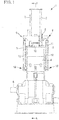
Fig. 1} Fig. 1 is a side view of illustrating the internal mixer according to one embodiment of the present invention. - {
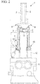
Fig. 2} Fig. 2 is a front view of illustrating the internal mixer according to one embodiment of the present invention. - {
Fig. 3} Fig. 3 is a cross sectional view taken along a line A-A ofFig. 1 . - {
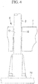
Fig. 4} Fig. 4 is a partial enlarged cross sectional view of illustrating a sliding portion. - {
Fig. 5} Fig. 5 is a front view of illustrating a first connection portion. - {
Fig. 6} Fig. 6 is a cross sectional view taken along a line B-B ofFig. 5 . - {
Fig. 7} Fig. 7 is a cross sectional view taken along a line C-C ofFig. 5 . - {
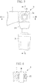
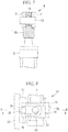
Fig. 8} Fig. 8 is a side view of illustrating a second connection portion. - {
Fig. 9} Fig. 9 is a cross sectional view taken along a line D-D ofFig. 8 . - {
Fig. 10} Fig. 10 is a front view of illustrating the second connection portion. - Hereinafter, the embodiment of the present invention will be described with reference to the drawings.
- With reference to
Fig. 1 to Fig. 3 , description will now be provided on the configuration of an internal mixer 1 according to one embodiment of the present invention. - The internal mixer 1 includes a
mixing chamber 5 havingrotors 6 incorporated at a lower portion of ahopper 12, and mixes and kneads a material in themixing chamber 5. A material to be mixed and kneaded may be a raw material used in various rubber products such as a tire for an automobile. - The
hopper 12 has a hollow thereinside, and is provided with aninput port 4 on its side face so as to be opened and closed, and input the material into thehopper 12. Eachhydraulic cylinder 3 is fixed at its head to the side face of thehopper 12 such that thehydraulic cylinder 3 is disposed so as to extend along the side face of thehopper 12. - The internal mixer 1 includes a floating
weight 15, arod member 14, a connectingbeam 7, thehydraulic cylinders 3, and aguide rod 2 and others. In the present embodiment, a portion where the connectingbeam 7 and theguide rod 2 slide relative to each other is referred to as a slidingportion 8, a connection portion where the connectingbeam 7 and eachhydraulic cylinder 3 are connected to each other is referred to as afirst connection portion 9, and a connection portion where thehopper 12 and eachhydraulic cylinder 3 are connected to each other is referred to as asecond connection portion 10. - The floating
weight 15 is disposed inside thehopper 12 and at the upper portion of the mixingchamber 5. The bottom surface of the floatingweight 15 is in contact with the material, and the top surface thereof is connected to therod member 14. The floatingweight 15 pushes down the top of the material in the mixingchamber 5 while therotors 6 are mixing and kneading the material in the mixingchamber 5. Accordingly, the floatingweight 15 is subjected to forces in various directions such as vertical and horizontal directions during mixing and kneading the material. The floatingweight 15 is movable upward and downward along with the movement of therod member 14. - The
rod member 14 is disposed in thehopper 12 so as to have an axial direction identical to the vertical direction of thehopper 12, and the upper end of therod member 14 extends through the hoppertop surface 11. Therod member 14 is connected at its lower end to the floatingweight 15 so as to support the floatingweight 15. Therod member 14 is connected at its upper end to the connectingbeam 7 at a position above the hoppertop surface 11. Therod member 14 is movable upward and downward in its axial direction along with the movement of the connectingbeam 7. - The
guide member 13 is disposed on the outer surface of the hoppertop surface 11, and a through hole through which therod member 14 is inserted is formed in theguide member 13. Therod member 14 slides along the inner peripheral wall of the through hole of theguide member 13. - The connecting
beam 7 may be a long horizontal member extending in one direction and disposed perpendicular to the axial direction of therod member 14, for example. The connectingbeam 7 is connected at its middle portion to the upper end of therod member 14, and connected at its each end to eachhydraulic cylinder 3, respectively. A through hole for inserting aguide rod 2 therethrough is formed in the connectingbeam 7. - The
guide rod 2 is a rod member, and its lower end is disposed on the hoppertop surface 11. Twoguide rods 2 may be provided, for example, and the respective rods are disposed such that each axial direction of theguide rods 2 is parallel to the axial direction of therod member 14. Eachguide rod 2 extends through the through hole formed in the connectingbeam 7. Since theguide rods 2 have axes parallel to the axial direction of therod member 14, when the connectingbeam 7 moves along theguide rods 2 through the through holes, the movement direction of the connectingbeam 7 is identical to the axial direction of therod member 14. - The
hydraulic cylinder 3 is one example of a cylinder, and may be an oil-hydraulic cylinder, for example. Thehydraulic cylinders 3 may be disposed at two positions along the side face of thehopper 12, for example. Eachhydraulic cylinder 3 is connected to the connectingbeam 7 and to thehopper 12 such that a piston rod at the upper end of thehydraulic cylinder 3 is connected to the connectingbeam 7, and the head at the lower end of thehydraulic cylinder 3 where its piston rod do not come outside is connected to the side face of thehopper 12. Eachhydraulic cylinder 3 is activated so as to move the connectingbeam 7 upward and downward relative to thehopper 12. Specifically, the connectingbeam 7 moves in the axial direction of therod member 14, and therod member 14 connected to the connectingbeam 7 also moves together with the floatingweight 15 fixed to therod member 14 in the axial direction of therod member 14. - With reference to
Fig. 4 , description will now be provided on the slidingportion 8. - The sliding
portion 8 includes eachguide rod 2 fixed to the hoppertop surface 11 and each throughhole 17 formed in the connectingbeam 7 for inserting eachguide rod 2 therethrough. The axial direction of each throughhole 17 is disposed to be parallel to the upward and downward direction of the floatingweight 15. Aguide bush 16 is inserted in each throughhole 17, and the connectingbeam 7 slides along eachguide rod 2 through aguide bush 16. Accordingly, when the connectingbeam 7 moves upward above the hoppertop surface 11, the connectingbeam 7 is supported by a pair of theguide rods 2 in the direction vertical to the axial direction of eachguide rod 2. - With reference to
Fig. 5 to Fig. 7 , description will now be provided on thefirst connection portion 9. - The
first connection portion 9 denotes the connection portion between the connectingbeam 7 and eachhydraulic cylinder 3. Thefirst connection portion 9 allows eachhydraulic cylinder 3 to be at least biaxially rotatable around the connection portion between the connectingbeam 7 and eachhydraulic cylinder 3. - The
first connection portion 9 has a configuration as illustrated inFig. 5 to Fig. 7 , for example. Specifically, acoupling bracket 20 is disposed at the tip end of the piston rod of eachcylinder 3, and thecoupling bracket 20 is inserted in a groove provided in the connectingbeam 7. Apin 19 is inserted through both of aspherical bearing 18 disposed to thecoupling bracket 20 and the connectingbeam 7. - This configuration connects the connecting
beam 7 and eachhydraulic cylinder 3 to each other. The configuration of using thespherical bearing 18 at the connection portion between the connectingbeam 7 and eachhydraulic cylinder 3 not only enables a single-axial rotation of eachhydraulic cylinder 3 through a hinge coupling, but also allows eachhydraulic cylinder 3 to be movable in various angular directions. - With reference to
Fig. 8 to Fig. 10 , description will now be provided on thesecond connection portion 10. - The
second connection portion 10 is a connection portion between thehopper 12 and eachhydraulic cylinder 3. Thesecond connection portion 10 allows thehydraulic cylinder 3 to be at least biaxially rotatable around the connection portion between thehopper 12 and eachhydraulic cylinder 3. - The
second connection portion 10 has a configuration as illustrated inFig. 8 to Fig. 10 , for example. Specifically, a pair ofsupport brackets 21 supporting apin 24 to thehopper 12 are disposed opposite to each other. Thepin 24 is fixed to thesupport brackets 21 so as to be parallel to the side face of thehopper 12.Adaptor members support brackets 21. Theseadaptor members hole 23 through which thepin 24 is inserted is formed in eachadaptor member 22, and a throughhole 26 through which thepin 28 is inserted is formed in eachadaptor member 25. Asupport member 27 having thepin 28 is installed in the adaptor constituted by theadaptor members pin 28 is fixed to thesupport member 27 so as to be vertical to the side face of thehopper 12. Thesupport member 27 accommodates the head of eachhydraulic cylinder 3 as well as supports thehydraulic cylinder 3. The structure of thesupport member 27 and thepin 28 may be embodied by installing a trunnion to eachhydraulic cylinder 3. - The
hopper 12 and eachhydraulic cylinder 3 are connected to each other through the above described configuration. In addition, the twopins adaptor members support member 27 are provided at the connection portion between thehopper 12 and eachhydraulic cylinder 3, so as to allow eachhydraulic cylinder 3 to be biaxially rotatable. This configuration enables a single-axial rotation of eachhydraulic cylinder 3 through a hinge coupling, but also allows eachcylinder 3 to be movable in various angular directions. - Description will now be provided on the advantageous effects of the internal mixer 1 according to the present embodiment.
- In the internal mixer 1, bending stress may act on the
hydraulic cylinders 3 if the gap between therod member 14 and theguide member 13 becomes greater because of abrasion due to repetitive operations, or the amount of movement of the connectingbeam 7 becomes greater due to the inclination of the connectingbeam 7. - To the contrary, according to the present invention, the spherical bearing is used at the
first connection portion 9 at the tip end of the piston rod of eachhydraulic cylinder 3, so that the piston rod of eachhydraulic cylinder 3 becomes movable in various angular directions. In addition, the twopins second connection portion 10 at the head of eachhydraulic cylinder 3, which enables the head of eachhydraulic cylinder 3 to be movable in various angular directions in accordance with the movement of the piston rod of eachhydraulic cylinder 3. - Force is applied onto the floating
weight 15 in various directions such as vertical and horizontal directions during mixing and kneading the material, and even if force in various directions is transferred to thehydraulic cylinders 3 through therod member 14 or the connectingbeam 7, the first and thesecond connection portions hydraulic cylinder 3 to be inclined in various angular directions. As a result, the internal mixer 1 according to the present embodiment prevents bending stress from acting on thehydraulic cylinders 3. Accordingly, it is possible to prevent damages on the components of thehydraulic cylinders 3 and to secure a smooth operation of thehydraulic cylinders 3. - The
plural guide rods 2 are disposed on the hoppertop surface 11, and theguide rods 2 and theguide bushes 16 at the throughholes 17 formed in the connectingbeams 7 slide relative to each other, so that the connectingbeam 7 moves upward and downward along theguide rods 2. As a result, even if the pluralhydraulic cylinders 3 work asynchronously so that the connectingbeam 7 becomes inclined, the connectingbeam 7 can be forcibly maintained to be horizontal relative to the vertical direction of thehopper 12. Accordingly, it is possible to secure a smooth upward and downward movement of the floatingweight 15 without inclining therod member 14 connected to the connectingbeam 7 and without causing abnormal abrasion to theguide member 13 along which therod member 14 slides -
- 1
- Internal mixer
- 2
- Guide rod
- 3
- Hydraulic cylinder (cylinder)
- 4
- Input port
- 5
- Mixing chamber
- 6
- Rotor
- 7
- Connecting beam
- 8
- Sliding portion
- 9
- First connection portion
- 10
- Second connection portion
- 11
- Hopper top surface
- 12
- Hopper (body)
- 13
- Guide member
- 14
- Rod member
- 15
- Floating weight
- 16
- Guide bush
- 17
- Through hole
- 18
- Spherical bearing
- 19
- Pin
- 20
- Coupling bracket
- 21
- Support bracket
- 22, 25
- Adaptor members
- 23, 26
- Through holes
- 24, 28
- Pins
- 27
- Support member
Claims (2)
- An internal mixer (1) comprising:a body (12) having a mixing chamber (5) thereinside;a floating weight (15) for pushing a material in the mixing chamber (5);a rod member (14) which is disposed in the body (12) so that one end of the rod member (14) is fixed to the floating weight (15) and an upper end of the rod member (14) extends through a body top surface (11), the rod member (14) being movable in an axial direction thereof;a connecting beam (7) whose middle portion is fixed to another end of the rod member (14);two cylinders (3) including a first and a second cylinder (3), wherein one end of the first cylinder (3) is connected to an end of the connecting beam (7) and the other end of the first cylinder (3) is connected to the body (12), wherein one end of the second cylinder (3) is connected to another end of the connecting beam (7) and the other end of the second cylinder (3) is connected to the body (12), so as to be able to move the connecting beam (7) in an axial direction of the rod member (14);a first connection portion (9) provided at a connection portion between the connecting beam (7) and each cylinder (3), wherein the first connection portion (9) allows each cylinder (3) to be at least biaxially rotatable around the first connection portion (9) between the connecting beam (7) and each cylinder (3); anda guide rod (2) disposed to the body (12) and having an axis parallel to the axial direction of the rod member (14),characterized in thatthe internal mixer (1) comprises a guide member (13) disposed on an outer surface of the body top surface (11), and a through hole through which the rod member (14) is inserted is formed in the guide member (13) such that the rod member (14) slides along the inner peripheral wall of the through hole of the guide member (13),the connecting beam (7) is provided with a through hole (17) through which the guide rod (2) is inserted, and a guide bush (16) is inserted in the through hole (17),the connecting beam (7) is arranged to move along the guide rod (2) through the through hole (17) in the axial direction of the rod member (14) and the connecting beam (7) slides along the guide rod (2) through the guide bush (16),the first connection portion (9) has a spherical bearing (18) at the connection portion between the connection portion (9) and each cylinder (3).the internal mixer (1) further comprises a second connection portion (10) provided at a connection portion between the body (12) and each cylinder (3), wherein each cylinder (3) is at least biaxially rotatable around the second connection portion (10), andthe second connection portion (10) includes:a first pin (24) fixed to a pair of support brackets (21) so as to be parallel to a side face of the body (12),adaptor members (22,25) disposed between the pair of support brackets (21), wherein the adaptor members (22, 25) constitute four sides of an adaptor that is a frame member,a support member (27) installed in the adaptor constituted by the adaptor members (22, 25), anda second pin (28) fixed to the support member (27) so as to be perpendicular to the side face of the body (12).
- The internal mixer (1) according to claim 1, wherein
the first pin (24) is inserted through a through hole (23) that is formed in each of first adaptor members (22), and
the second pin (28) is inserted through a through hole (26) that is formed in each of second adaptor members (25), so that the first and second pins (24,28) are perpendicular to each other.
Applications Claiming Priority (2)
| Application Number | Priority Date | Filing Date | Title |
|---|---|---|---|
| JP2011031430A JP5791303B2 (en) | 2011-02-16 | 2011-02-16 | Kneading equipment |
| PCT/JP2011/060553 WO2012111178A1 (en) | 2011-02-16 | 2011-05-02 | Kneading device |
Publications (4)
| Publication Number | Publication Date |
|---|---|
| EP2676779A1 EP2676779A1 (en) | 2013-12-25 |
| EP2676779A4 EP2676779A4 (en) | 2014-08-27 |
| EP2676779B1 EP2676779B1 (en) | 2017-04-26 |
| EP2676779B2 true EP2676779B2 (en) | 2021-02-24 |
Family
ID=46672134
Family Applications (1)
| Application Number | Title | Priority Date | Filing Date |
|---|---|---|---|
| EP11858598.3A Not-in-force EP2676779B2 (en) | 2011-02-16 | 2011-05-02 | Internal mixer |
Country Status (6)
| Country | Link |
|---|---|
| EP (1) | EP2676779B2 (en) |
| JP (1) | JP5791303B2 (en) |
| KR (2) | KR101564805B1 (en) |
| CN (1) | CN103052478B (en) |
| TW (1) | TWI478802B (en) |
| WO (1) | WO2012111178A1 (en) |
Families Citing this family (5)
| Publication number | Priority date | Publication date | Assignee | Title |
|---|---|---|---|---|
| JP6159027B2 (en) * | 2015-02-05 | 2017-07-05 | 三菱重工マシナリーテクノロジー株式会社 | Kneading machine |
| CN104999582A (en) * | 2015-08-05 | 2015-10-28 | 大连橡胶塑料机械股份有限公司 | Material pressing device of internal mixer |
| CN106426598A (en) * | 2016-08-30 | 2017-02-22 | 安正(天津)新材料股份有限公司 | Mixing device for PVC production line |
| CN106426608A (en) * | 2016-08-30 | 2017-02-22 | 安正(天津)新材料股份有限公司 | Automatic feeding system of PVC production line |
| JP2019020116A (en) * | 2018-10-15 | 2019-02-07 | シャープ株式会社 | Air conditioning system for food processing |
Citations (2)
| Publication number | Priority date | Publication date | Assignee | Title |
|---|---|---|---|---|
| DE3426442C1 (en) † | 1984-07-18 | 1985-12-05 | Werner & Pfleiderer, 7000 Stuttgart | Hydraulic feeding device for an internal mixer for the preparation of plastic masses |
| EP0272338A1 (en) † | 1986-12-20 | 1988-06-29 | Continental Aktiengesellschaft | Internal mixer |
Family Cites Families (13)
| Publication number | Priority date | Publication date | Assignee | Title |
|---|---|---|---|---|
| US3202062A (en) * | 1962-04-23 | 1965-08-24 | Ling Temco Vought Inc | Actuator |
| US3314336A (en) * | 1963-05-20 | 1967-04-18 | Licentia Gmbh | Ball and socket joint for cylinder head |
| US4318572A (en) * | 1980-01-11 | 1982-03-09 | Mts Systems Corporation | Tension-compression swivel joint with hydraulic force reaction |
| JPS6319207A (en) * | 1986-07-11 | 1988-01-27 | Mitsubishi Heavy Ind Ltd | Hermetically closed type kneader |
| JPS6359342A (en) * | 1986-08-29 | 1988-03-15 | Mitsubishi Heavy Ind Ltd | Hermetically closed type kneader |
| JPH01262934A (en) * | 1988-04-08 | 1989-10-19 | Continental Gummi Werke Ag | Kneader |
| US4877328A (en) * | 1988-04-12 | 1989-10-31 | Continental Aktiengesellschaft | Internal mixer |
| JPH0775659B2 (en) * | 1989-06-13 | 1995-08-16 | 鈴鹿エンヂニヤリング株式会社 | Closed pressure kneader |
| IT1269896B (en) * | 1994-03-22 | 1997-04-16 | Pomini Spa | EQUIPMENT WITH OPPOSITE CYLINDERS TO OPERATE THE BAR OF A PRESSURE ELEMENT (OF MIXES IN PROCESSING) IN INTERNAL TYPE MACHINES |
| JP3137894B2 (en) * | 1996-01-31 | 2001-02-26 | 株式会社神戸製鋼所 | Closed kneader |
| KR19980018239A (en) * | 1996-08-02 | 1998-06-05 | 이시이 시게하루 | Kneading device |
| JP3474725B2 (en) * | 1997-01-30 | 2003-12-08 | 株式会社神戸製鋼所 | Weight device in closed kneader |
| JP3207381B2 (en) * | 1997-10-08 | 2001-09-10 | 株式会社新日南 | Kneading device |
-
2011
- 2011-02-16 JP JP2011031430A patent/JP5791303B2/en active Active
- 2011-05-02 CN CN201180027448.7A patent/CN103052478B/en not_active Expired - Fee Related
- 2011-05-02 KR KR1020127031745A patent/KR101564805B1/en active Active
- 2011-05-02 EP EP11858598.3A patent/EP2676779B2/en not_active Not-in-force
- 2011-05-02 WO PCT/JP2011/060553 patent/WO2012111178A1/en not_active Ceased
- 2011-05-02 KR KR1020147022618A patent/KR20140107682A/en not_active Withdrawn
-
2012
- 2012-01-12 TW TW101101289A patent/TWI478802B/en not_active IP Right Cessation
Patent Citations (2)
| Publication number | Priority date | Publication date | Assignee | Title |
|---|---|---|---|---|
| DE3426442C1 (en) † | 1984-07-18 | 1985-12-05 | Werner & Pfleiderer, 7000 Stuttgart | Hydraulic feeding device for an internal mixer for the preparation of plastic masses |
| EP0272338A1 (en) † | 1986-12-20 | 1988-06-29 | Continental Aktiengesellschaft | Internal mixer |
Also Published As
| Publication number | Publication date |
|---|---|
| JP2012166524A (en) | 2012-09-06 |
| EP2676779A4 (en) | 2014-08-27 |
| WO2012111178A1 (en) | 2012-08-23 |
| CN103052478B (en) | 2016-05-11 |
| CN103052478A (en) | 2013-04-17 |
| KR20130023268A (en) | 2013-03-07 |
| KR20140107682A (en) | 2014-09-04 |
| JP5791303B2 (en) | 2015-10-07 |
| EP2676779A1 (en) | 2013-12-25 |
| TWI478802B (en) | 2015-04-01 |
| TW201235175A (en) | 2012-09-01 |
| EP2676779B1 (en) | 2017-04-26 |
| KR101564805B1 (en) | 2015-10-30 |
Similar Documents
| Publication | Publication Date | Title |
|---|---|---|
| EP2676779B2 (en) | Internal mixer | |
| EP2098339B1 (en) | Parallel mechanism | |
| US4732525A (en) | Robot | |
| RU2558324C2 (en) | Parallel kinematic mechanism with cardan type holders | |
| EP4316791A1 (en) | Mechanical drum suspension turn-up forming structure | |
| KR101714730B1 (en) | A control system for controlling collective and cyclic pitch of rotor blades of a multi-blade rotor in a rotary-wing aircraft | |
| KR102121711B1 (en) | Link structure for excavator bucket with rotation and tilt control | |
| CN106132579A (en) | Bending auxiliary device for flanging press | |
| CA3030496A1 (en) | Link with swivel ball bushing rotatable in opposing directions | |
| KR101844210B1 (en) | A tilting device for excavator bucket | |
| EP1835101A2 (en) | Hinge for a frame | |
| CN105952471B (en) | Duct piece assembling machine and road heading machinery including the duct piece assembling machine | |
| CN111168649A (en) | High-speed and high-precision parallel robot | |
| KR20020001784A (en) | Tilting device | |
| CN215287812U (en) | Scissor lift and AGV trolley | |
| CN212222205U (en) | Crawler frame telescopic device and crane | |
| CN101858197A (en) | Be used to hole or the driver element of building implements | |
| CN224030484U (en) | Battery lifting appliance and battery replacing station | |
| CN119981088B (en) | Foldable universal mechanical structure for supporting foundation pit supporting groove steel plate | |
| CN220907082U (en) | Arm support structure, fire-fighting vehicle and engineering vehicle | |
| CN222864058U (en) | Connecting seat and double-speed reducer connecting structure | |
| KR102060350B1 (en) | Parallel goniometer for electromicroscopy | |
| CN220469823U (en) | Dual-drive pitching mechanism of airborne drilling machine | |
| CN120620137A (en) | Automatic tilter bearing disassembly device for tiltrotor aircraft | |
| CN112192136B (en) | Clamping tool |
Legal Events
| Date | Code | Title | Description |
|---|---|---|---|
| PUAI | Public reference made under article 153(3) epc to a published international application that has entered the european phase |
Free format text: ORIGINAL CODE: 0009012 |
|
| 17P | Request for examination filed |
Effective date: 20121207 |
|
| AK | Designated contracting states |
Kind code of ref document: A1 Designated state(s): AL AT BE BG CH CY CZ DE DK EE ES FI FR GB GR HR HU IE IS IT LI LT LU LV MC MK MT NL NO PL PT RO RS SE SI SK SM TR |
|
| DAX | Request for extension of the european patent (deleted) | ||
| A4 | Supplementary search report drawn up and despatched |
Effective date: 20140725 |
|
| RIC1 | Information provided on ipc code assigned before grant |
Ipc: B29B 7/18 20060101AFI20140721BHEP Ipc: B29B 7/24 20060101ALI20140721BHEP Ipc: F15B 15/04 20060101ALN20140721BHEP |
|
| 17Q | First examination report despatched |
Effective date: 20150601 |
|
| REG | Reference to a national code |
Ref country code: DE Ref legal event code: R079 Ref document number: 602011037440 Country of ref document: DE Free format text: PREVIOUS MAIN CLASS: B29B0007240000 Ipc: B29B0007180000 |
|
| RIC1 | Information provided on ipc code assigned before grant |
Ipc: F15B 15/04 20060101ALN20160916BHEP Ipc: B29B 7/18 20060101AFI20160916BHEP Ipc: B29B 7/24 20060101ALI20160916BHEP |
|
| GRAP | Despatch of communication of intention to grant a patent |
Free format text: ORIGINAL CODE: EPIDOSNIGR1 |
|
| INTG | Intention to grant announced |
Effective date: 20161202 |
|
| GRAS | Grant fee paid |
Free format text: ORIGINAL CODE: EPIDOSNIGR3 |
|
| GRAA | (expected) grant |
Free format text: ORIGINAL CODE: 0009210 |
|
| AK | Designated contracting states |
Kind code of ref document: B1 Designated state(s): AL AT BE BG CH CY CZ DE DK EE ES FI FR GB GR HR HU IE IS IT LI LT LU LV MC MK MT NL NO PL PT RO RS SE SI SK SM TR |
|
| REG | Reference to a national code |
Ref country code: GB Ref legal event code: FG4D |
|
| REG | Reference to a national code |
Ref country code: CH Ref legal event code: EP |
|
| REG | Reference to a national code |
Ref country code: AT Ref legal event code: REF Ref document number: 887473 Country of ref document: AT Kind code of ref document: T Effective date: 20170515 |
|
| REG | Reference to a national code |
Ref country code: IE Ref legal event code: FG4D |
|
| REG | Reference to a national code |
Ref country code: DE Ref legal event code: R096 Ref document number: 602011037440 Country of ref document: DE |
|
| REG | Reference to a national code |
Ref country code: NL Ref legal event code: MP Effective date: 20170426 |
|
| REG | Reference to a national code |
Ref country code: LT Ref legal event code: MG4D |
|
| REG | Reference to a national code |
Ref country code: AT Ref legal event code: MK05 Ref document number: 887473 Country of ref document: AT Kind code of ref document: T Effective date: 20170426 |
|
| PG25 | Lapsed in a contracting state [announced via postgrant information from national office to epo] |
Ref country code: NL Free format text: LAPSE BECAUSE OF FAILURE TO SUBMIT A TRANSLATION OF THE DESCRIPTION OR TO PAY THE FEE WITHIN THE PRESCRIBED TIME-LIMIT Effective date: 20170426 |
|
| PG25 | Lapsed in a contracting state [announced via postgrant information from national office to epo] |
Ref country code: FI Free format text: LAPSE BECAUSE OF FAILURE TO SUBMIT A TRANSLATION OF THE DESCRIPTION OR TO PAY THE FEE WITHIN THE PRESCRIBED TIME-LIMIT Effective date: 20170426 Ref country code: LT Free format text: LAPSE BECAUSE OF FAILURE TO SUBMIT A TRANSLATION OF THE DESCRIPTION OR TO PAY THE FEE WITHIN THE PRESCRIBED TIME-LIMIT Effective date: 20170426 Ref country code: HR Free format text: LAPSE BECAUSE OF FAILURE TO SUBMIT A TRANSLATION OF THE DESCRIPTION OR TO PAY THE FEE WITHIN THE PRESCRIBED TIME-LIMIT Effective date: 20170426 Ref country code: ES Free format text: LAPSE BECAUSE OF FAILURE TO SUBMIT A TRANSLATION OF THE DESCRIPTION OR TO PAY THE FEE WITHIN THE PRESCRIBED TIME-LIMIT Effective date: 20170426 Ref country code: NO Free format text: LAPSE BECAUSE OF FAILURE TO SUBMIT A TRANSLATION OF THE DESCRIPTION OR TO PAY THE FEE WITHIN THE PRESCRIBED TIME-LIMIT Effective date: 20170726 Ref country code: GR Free format text: LAPSE BECAUSE OF FAILURE TO SUBMIT A TRANSLATION OF THE DESCRIPTION OR TO PAY THE FEE WITHIN THE PRESCRIBED TIME-LIMIT Effective date: 20170727 Ref country code: AT Free format text: LAPSE BECAUSE OF FAILURE TO SUBMIT A TRANSLATION OF THE DESCRIPTION OR TO PAY THE FEE WITHIN THE PRESCRIBED TIME-LIMIT Effective date: 20170426 |
|
| PG25 | Lapsed in a contracting state [announced via postgrant information from national office to epo] |
Ref country code: PL Free format text: LAPSE BECAUSE OF FAILURE TO SUBMIT A TRANSLATION OF THE DESCRIPTION OR TO PAY THE FEE WITHIN THE PRESCRIBED TIME-LIMIT Effective date: 20170426 Ref country code: BG Free format text: LAPSE BECAUSE OF FAILURE TO SUBMIT A TRANSLATION OF THE DESCRIPTION OR TO PAY THE FEE WITHIN THE PRESCRIBED TIME-LIMIT Effective date: 20170726 Ref country code: IS Free format text: LAPSE BECAUSE OF FAILURE TO SUBMIT A TRANSLATION OF THE DESCRIPTION OR TO PAY THE FEE WITHIN THE PRESCRIBED TIME-LIMIT Effective date: 20170826 Ref country code: LV Free format text: LAPSE BECAUSE OF FAILURE TO SUBMIT A TRANSLATION OF THE DESCRIPTION OR TO PAY THE FEE WITHIN THE PRESCRIBED TIME-LIMIT Effective date: 20170426 Ref country code: RS Free format text: LAPSE BECAUSE OF FAILURE TO SUBMIT A TRANSLATION OF THE DESCRIPTION OR TO PAY THE FEE WITHIN THE PRESCRIBED TIME-LIMIT Effective date: 20170426 Ref country code: SE Free format text: LAPSE BECAUSE OF FAILURE TO SUBMIT A TRANSLATION OF THE DESCRIPTION OR TO PAY THE FEE WITHIN THE PRESCRIBED TIME-LIMIT Effective date: 20170426 |
|
| REG | Reference to a national code |
Ref country code: CH Ref legal event code: PL |
|
| REG | Reference to a national code |
Ref country code: DE Ref legal event code: R026 Ref document number: 602011037440 Country of ref document: DE |
|
| PG25 | Lapsed in a contracting state [announced via postgrant information from national office to epo] |
Ref country code: SK Free format text: LAPSE BECAUSE OF FAILURE TO SUBMIT A TRANSLATION OF THE DESCRIPTION OR TO PAY THE FEE WITHIN THE PRESCRIBED TIME-LIMIT Effective date: 20170426 Ref country code: RO Free format text: LAPSE BECAUSE OF FAILURE TO SUBMIT A TRANSLATION OF THE DESCRIPTION OR TO PAY THE FEE WITHIN THE PRESCRIBED TIME-LIMIT Effective date: 20170426 Ref country code: DK Free format text: LAPSE BECAUSE OF FAILURE TO SUBMIT A TRANSLATION OF THE DESCRIPTION OR TO PAY THE FEE WITHIN THE PRESCRIBED TIME-LIMIT Effective date: 20170426 Ref country code: CZ Free format text: LAPSE BECAUSE OF FAILURE TO SUBMIT A TRANSLATION OF THE DESCRIPTION OR TO PAY THE FEE WITHIN THE PRESCRIBED TIME-LIMIT Effective date: 20170426 Ref country code: EE Free format text: LAPSE BECAUSE OF FAILURE TO SUBMIT A TRANSLATION OF THE DESCRIPTION OR TO PAY THE FEE WITHIN THE PRESCRIBED TIME-LIMIT Effective date: 20170426 Ref country code: MC Free format text: LAPSE BECAUSE OF FAILURE TO SUBMIT A TRANSLATION OF THE DESCRIPTION OR TO PAY THE FEE WITHIN THE PRESCRIBED TIME-LIMIT Effective date: 20170426 |
|
| PLBI | Opposition filed |
Free format text: ORIGINAL CODE: 0009260 |
|
| PLAX | Notice of opposition and request to file observation + time limit sent |
Free format text: ORIGINAL CODE: EPIDOSNOBS2 |
|
| REG | Reference to a national code |
Ref country code: IE Ref legal event code: MM4A |
|
| REG | Reference to a national code |
Ref country code: DE Ref legal event code: R082 Ref document number: 602011037440 Country of ref document: DE Representative=s name: HENKEL & PARTNER MBB PATENTANWALTSKANZLEI, REC, DE Ref country code: DE Ref legal event code: R082 Ref document number: 602011037440 Country of ref document: DE Representative=s name: PATENTANWAELTE HENKEL, BREUER & PARTNER, DE Ref country code: DE Ref legal event code: R081 Ref document number: 602011037440 Country of ref document: DE Owner name: MITSUBISHI HEAVY INDUSTRIES MACHINERY SYSTEMS,, JP Free format text: FORMER OWNER: MITSUBISHI HEAVY INDUSTRIES MACHINERY TECHNOLOGY CORPORATION, HIROSHIMA-SHI, HIROSHIMA, JP Ref country code: DE Ref legal event code: R082 Ref document number: 602011037440 Country of ref document: DE Representative=s name: PATENTANWAELTE HENKEL, BREUER & PARTNER MBB, DE |
|
| PG25 | Lapsed in a contracting state [announced via postgrant information from national office to epo] |
Ref country code: IT Free format text: LAPSE BECAUSE OF FAILURE TO SUBMIT A TRANSLATION OF THE DESCRIPTION OR TO PAY THE FEE WITHIN THE PRESCRIBED TIME-LIMIT Effective date: 20170426 Ref country code: CH Free format text: LAPSE BECAUSE OF NON-PAYMENT OF DUE FEES Effective date: 20170531 Ref country code: SM Free format text: LAPSE BECAUSE OF FAILURE TO SUBMIT A TRANSLATION OF THE DESCRIPTION OR TO PAY THE FEE WITHIN THE PRESCRIBED TIME-LIMIT Effective date: 20170426 Ref country code: LI Free format text: LAPSE BECAUSE OF NON-PAYMENT OF DUE FEES Effective date: 20170531 |
|
| 26 | Opposition filed |
Opponent name: HARBURG-FREUDENBERGER MASCHINENBAU GMBH Effective date: 20180126 |
|
| GBPC | Gb: european patent ceased through non-payment of renewal fee |
Effective date: 20170726 |
|
| PG25 | Lapsed in a contracting state [announced via postgrant information from national office to epo] |
Ref country code: LU Free format text: LAPSE BECAUSE OF NON-PAYMENT OF DUE FEES Effective date: 20170502 |
|
| REG | Reference to a national code |
Ref country code: BE Ref legal event code: MM Effective date: 20170531 |
|
| PG25 | Lapsed in a contracting state [announced via postgrant information from national office to epo] |
Ref country code: GB Free format text: LAPSE BECAUSE OF NON-PAYMENT OF DUE FEES Effective date: 20170726 Ref country code: IE Free format text: LAPSE BECAUSE OF NON-PAYMENT OF DUE FEES Effective date: 20170502 |
|
| REG | Reference to a national code |
Ref country code: FR Ref legal event code: ST Effective date: 20180416 |
|
| PG25 | Lapsed in a contracting state [announced via postgrant information from national office to epo] |
Ref country code: SI Free format text: LAPSE BECAUSE OF FAILURE TO SUBMIT A TRANSLATION OF THE DESCRIPTION OR TO PAY THE FEE WITHIN THE PRESCRIBED TIME-LIMIT Effective date: 20170426 |
|
| PLBB | Reply of patent proprietor to notice(s) of opposition received |
Free format text: ORIGINAL CODE: EPIDOSNOBS3 |
|
| PG25 | Lapsed in a contracting state [announced via postgrant information from national office to epo] |
Ref country code: FR Free format text: LAPSE BECAUSE OF NON-PAYMENT OF DUE FEES Effective date: 20170626 Ref country code: BE Free format text: LAPSE BECAUSE OF NON-PAYMENT OF DUE FEES Effective date: 20170531 |
|
| PG25 | Lapsed in a contracting state [announced via postgrant information from national office to epo] |
Ref country code: MT Free format text: LAPSE BECAUSE OF NON-PAYMENT OF DUE FEES Effective date: 20170502 |
|
| PG25 | Lapsed in a contracting state [announced via postgrant information from national office to epo] |
Ref country code: HU Free format text: LAPSE BECAUSE OF FAILURE TO SUBMIT A TRANSLATION OF THE DESCRIPTION OR TO PAY THE FEE WITHIN THE PRESCRIBED TIME-LIMIT; INVALID AB INITIO Effective date: 20110502 |
|
| PG25 | Lapsed in a contracting state [announced via postgrant information from national office to epo] |
Ref country code: CY Free format text: LAPSE BECAUSE OF NON-PAYMENT OF DUE FEES Effective date: 20170426 |
|
| PG25 | Lapsed in a contracting state [announced via postgrant information from national office to epo] |
Ref country code: MK Free format text: LAPSE BECAUSE OF FAILURE TO SUBMIT A TRANSLATION OF THE DESCRIPTION OR TO PAY THE FEE WITHIN THE PRESCRIBED TIME-LIMIT Effective date: 20170426 |
|
| PG25 | Lapsed in a contracting state [announced via postgrant information from national office to epo] |
Ref country code: TR Free format text: LAPSE BECAUSE OF FAILURE TO SUBMIT A TRANSLATION OF THE DESCRIPTION OR TO PAY THE FEE WITHIN THE PRESCRIBED TIME-LIMIT Effective date: 20170426 |
|
| PG25 | Lapsed in a contracting state [announced via postgrant information from national office to epo] |
Ref country code: PT Free format text: LAPSE BECAUSE OF FAILURE TO SUBMIT A TRANSLATION OF THE DESCRIPTION OR TO PAY THE FEE WITHIN THE PRESCRIBED TIME-LIMIT Effective date: 20170426 |
|
| PG25 | Lapsed in a contracting state [announced via postgrant information from national office to epo] |
Ref country code: AL Free format text: LAPSE BECAUSE OF FAILURE TO SUBMIT A TRANSLATION OF THE DESCRIPTION OR TO PAY THE FEE WITHIN THE PRESCRIBED TIME-LIMIT Effective date: 20170426 |
|
| PUAH | Patent maintained in amended form |
Free format text: ORIGINAL CODE: 0009272 |
|
| STAA | Information on the status of an ep patent application or granted ep patent |
Free format text: STATUS: PATENT MAINTAINED AS AMENDED |
|
| 27A | Patent maintained in amended form |
Effective date: 20210224 |
|
| AK | Designated contracting states |
Kind code of ref document: B2 Designated state(s): AL AT BE BG CH CY CZ DE DK EE ES FI FR GB GR HR HU IE IS IT LI LT LU LV MC MK MT NL NO PL PT RO RS SE SI SK SM TR |
|
| REG | Reference to a national code |
Ref country code: DE Ref legal event code: R102 Ref document number: 602011037440 Country of ref document: DE |
|
| PGFP | Annual fee paid to national office [announced via postgrant information from national office to epo] |
Ref country code: DE Payment date: 20240328 Year of fee payment: 14 |
|
| REG | Reference to a national code |
Ref country code: DE Ref legal event code: R119 Ref document number: 602011037440 Country of ref document: DE |
|
| PG25 | Lapsed in a contracting state [announced via postgrant information from national office to epo] |
Ref country code: DE Free format text: LAPSE BECAUSE OF NON-PAYMENT OF DUE FEES Effective date: 20251202 |