EP2676622A1 - Bone anchor - Google Patents
Bone anchor Download PDFInfo
- Publication number
- EP2676622A1 EP2676622A1 EP12172417.3A EP12172417A EP2676622A1 EP 2676622 A1 EP2676622 A1 EP 2676622A1 EP 12172417 A EP12172417 A EP 12172417A EP 2676622 A1 EP2676622 A1 EP 2676622A1
- Authority
- EP
- European Patent Office
- Prior art keywords
- anchor
- bone
- bone anchor
- core member
- anchor member
- Prior art date
- Legal status (The legal status is an assumption and is not a legal conclusion. Google has not performed a legal analysis and makes no representation as to the accuracy of the status listed.)
- Granted
Links
Images



Classifications
-
- A—HUMAN NECESSITIES
- A61—MEDICAL OR VETERINARY SCIENCE; HYGIENE
- A61B—DIAGNOSIS; SURGERY; IDENTIFICATION
- A61B17/00—Surgical instruments, devices or methods
- A61B17/56—Surgical instruments or methods for treatment of bones or joints; Devices specially adapted therefor
- A61B17/58—Surgical instruments or methods for treatment of bones or joints; Devices specially adapted therefor for osteosynthesis, e.g. bone plates, screws or setting implements
- A61B17/68—Internal fixation devices, including fasteners and spinal fixators, even if a part thereof projects from the skin
- A61B17/84—Fasteners therefor or fasteners being internal fixation devices
- A61B17/86—Pins or screws or threaded wires; nuts therefor
- A61B17/8605—Heads, i.e. proximal ends projecting from bone
-
- A—HUMAN NECESSITIES
- A61—MEDICAL OR VETERINARY SCIENCE; HYGIENE
- A61B—DIAGNOSIS; SURGERY; IDENTIFICATION
- A61B17/00—Surgical instruments, devices or methods
- A61B17/56—Surgical instruments or methods for treatment of bones or joints; Devices specially adapted therefor
- A61B17/58—Surgical instruments or methods for treatment of bones or joints; Devices specially adapted therefor for osteosynthesis, e.g. bone plates, screws or setting implements
- A61B17/68—Internal fixation devices, including fasteners and spinal fixators, even if a part thereof projects from the skin
- A61B17/686—Plugs, i.e. elements forming interface between bone hole and implant or fastener, e.g. screw
-
- A—HUMAN NECESSITIES
- A61—MEDICAL OR VETERINARY SCIENCE; HYGIENE
- A61B—DIAGNOSIS; SURGERY; IDENTIFICATION
- A61B17/00—Surgical instruments, devices or methods
- A61B17/56—Surgical instruments or methods for treatment of bones or joints; Devices specially adapted therefor
- A61B17/58—Surgical instruments or methods for treatment of bones or joints; Devices specially adapted therefor for osteosynthesis, e.g. bone plates, screws or setting implements
- A61B17/68—Internal fixation devices, including fasteners and spinal fixators, even if a part thereof projects from the skin
- A61B17/72—Intramedullary devices, e.g. pins or nails
- A61B17/7233—Intramedullary devices, e.g. pins or nails with special means of locking the nail to the bone
- A61B17/725—Intramedullary devices, e.g. pins or nails with special means of locking the nail to the bone with locking pins or screws of special form
-
- A—HUMAN NECESSITIES
- A61—MEDICAL OR VETERINARY SCIENCE; HYGIENE
- A61B—DIAGNOSIS; SURGERY; IDENTIFICATION
- A61B17/00—Surgical instruments, devices or methods
- A61B17/56—Surgical instruments or methods for treatment of bones or joints; Devices specially adapted therefor
- A61B17/58—Surgical instruments or methods for treatment of bones or joints; Devices specially adapted therefor for osteosynthesis, e.g. bone plates, screws or setting implements
- A61B17/68—Internal fixation devices, including fasteners and spinal fixators, even if a part thereof projects from the skin
- A61B17/84—Fasteners therefor or fasteners being internal fixation devices
- A61B17/86—Pins or screws or threaded wires; nuts therefor
- A61B17/8685—Pins or screws or threaded wires; nuts therefor comprising multiple separate parts
-
- A—HUMAN NECESSITIES
- A61—MEDICAL OR VETERINARY SCIENCE; HYGIENE
- A61L—METHODS OR APPARATUS FOR STERILISING MATERIALS OR OBJECTS IN GENERAL; DISINFECTION, STERILISATION OR DEODORISATION OF AIR; CHEMICAL ASPECTS OF BANDAGES, DRESSINGS, ABSORBENT PADS OR SURGICAL ARTICLES; MATERIALS FOR BANDAGES, DRESSINGS, ABSORBENT PADS OR SURGICAL ARTICLES
- A61L27/00—Materials for grafts or prostheses or for coating grafts or prostheses
- A61L27/14—Macromolecular materials
-
- A—HUMAN NECESSITIES
- A61—MEDICAL OR VETERINARY SCIENCE; HYGIENE
- A61B—DIAGNOSIS; SURGERY; IDENTIFICATION
- A61B17/00—Surgical instruments, devices or methods
- A61B17/56—Surgical instruments or methods for treatment of bones or joints; Devices specially adapted therefor
- A61B17/58—Surgical instruments or methods for treatment of bones or joints; Devices specially adapted therefor for osteosynthesis, e.g. bone plates, screws or setting implements
- A61B17/68—Internal fixation devices, including fasteners and spinal fixators, even if a part thereof projects from the skin
- A61B17/84—Fasteners therefor or fasteners being internal fixation devices
- A61B17/86—Pins or screws or threaded wires; nuts therefor
- A61B17/8625—Shanks, i.e. parts contacting bone tissue
- A61B17/8635—Tips of screws
-
- A—HUMAN NECESSITIES
- A61—MEDICAL OR VETERINARY SCIENCE; HYGIENE
- A61B—DIAGNOSIS; SURGERY; IDENTIFICATION
- A61B17/00—Surgical instruments, devices or methods
- A61B17/56—Surgical instruments or methods for treatment of bones or joints; Devices specially adapted therefor
- A61B17/58—Surgical instruments or methods for treatment of bones or joints; Devices specially adapted therefor for osteosynthesis, e.g. bone plates, screws or setting implements
- A61B17/68—Internal fixation devices, including fasteners and spinal fixators, even if a part thereof projects from the skin
- A61B17/84—Fasteners therefor or fasteners being internal fixation devices
- A61B17/86—Pins or screws or threaded wires; nuts therefor
- A61B17/864—Pins or screws or threaded wires; nuts therefor hollow, e.g. with socket or cannulated
-
- A—HUMAN NECESSITIES
- A61—MEDICAL OR VETERINARY SCIENCE; HYGIENE
- A61B—DIAGNOSIS; SURGERY; IDENTIFICATION
- A61B17/00—Surgical instruments, devices or methods
- A61B17/56—Surgical instruments or methods for treatment of bones or joints; Devices specially adapted therefor
- A61B17/58—Surgical instruments or methods for treatment of bones or joints; Devices specially adapted therefor for osteosynthesis, e.g. bone plates, screws or setting implements
- A61B17/68—Internal fixation devices, including fasteners and spinal fixators, even if a part thereof projects from the skin
- A61B17/84—Fasteners therefor or fasteners being internal fixation devices
- A61B17/86—Pins or screws or threaded wires; nuts therefor
- A61B17/866—Material or manufacture
Definitions
- the invention relates to a bone anchor comprising an anchor member with a tubular section and a bone engagement structure for engaging the bone in at least a portion of the tubular section and further comprising a core member being insertable into the anchor member and connectable thereto.
- the anchor member is made of a material that is more flexible than a material of the core member.
- the bone anchor can be used in a bone fixation or stabilization arrangement and it is especially suitable for anchoring fixation or stabilization devices in osteoporotic bones.
- US 2010/082071 A1 describes a composite screw preferably made of a metallic pin embedded in a polymeric tubular structure having outwardly facing threads, wherein the metallic pin comprises a screw head, an intermediate shaft and a screw tip, and the polymeric threaded tube is either molded onto the metallic shaft or the thread is machined after molding a polymeric structure onto the shaft.
- the composite screw has a variable stiffness along the screw shaft from the tip to the head.
- the composite screw is meant to reduce the stiffness of the screw by introducing a polymeric thread.
- US 6,168,597 B1 describes a bone screw with a threaded shaft portion, a longitudinal bore provided in the shaft, a head and a flared portion which flares towards the free end opposite to the head. Slits extending parallel to the longitudinal axis are provided in this portion of the threaded shaft.
- An expanding member comprises a top portion forming the top of the bone screw and the shaft. The expanding member is first pushed into the bore and then the screw together with the expanding member is screwed into the bone. Thereafter, the bone screw can be expanded within the bone by pulling the top portion of the expanding member into the longitudinal bore of the shaft portion.
- the anchor member of the bone anchor is made of a material that is more flexible than the material of the core member. Therefore, an overall stiffness of the bone anchor is reduced compared to the stiffness of a bone anchor that consists of metallic components only.
- the material of the anchor member is a polymer material and the material of the core member is a metallic material.
- the bone anchor has the advantage that the anchor member can be inserted separately into the bone and thereafter the core member can be inserted. Because the core member can be inserted by a sliding motion into the anchor member without any screwing operation, the insertion of the core member can be carried out quickly and in a simple manner. Alternatively, the anchor member and the core member can be pre-assembled and screwed into the bone as a whole.
- an appropriate stiffness of the bone anchor can be achieved.
- the bone anchor can be used with all known polyaxial receiving parts and other stabilization devices. Because the head is made from a material that is commonly used for stabilization and/or fixation devices, the head can be effectively connected and fixed to such stabilization and/or fixation devices.
- the anchor member provides for an improved long-term anchoring in the bone.
- the bone anchor according to a first embodiment comprises an anchor member 1, in the form of a screw member and a core member 2.
- the core member 2 can be inserted into the anchor member 1 and connected thereto to form the bone anchor.
- the anchor member 1 has a first end 11, an opposite second end 12 and a longitudinal axis L extending through the first end 11 and the second end 12.
- the anchor member is formed as a tubular member and has a first section 13 with a first inner diameter, the first section extending from the first end 11 to a distance from the second end 12.
- the inner diameter is gradually reduced towards the second end 12.
- the second section 14 comprises a tapered inner surface 14a tapering towards the second end 12.
- At the second end 12, at least two, preferably three or four slits 15 are provided that are open to the second end 12 and extend into the first section 13.
- the slits 15 are substantially parallel to the longitudinal axis L.
- the front face of the second end 12 defines an abutment for a portion of the core member when the core member is fully inserted as shown in Figs. 1 and 13a, 13b.
- At least a portion of the outer surface on the anchor member 1 is provided with a bone thread 16.
- another bone engagement structure may be provided, such as, for example, barbs or a textured surface.
- a plurality of recesses 17 are extending from the front face of the first end 11 into the first tubular section 13 and form engagement portions for a form-fit engagement with the head 3.
- the anchor member 1 is made of a material that has a smaller modulus of elasticity compared to a modulus of elasticity of the material of the core member 2.
- the anchor member 1 is made of a polymer material, in particular a biocompatible polymer material.
- the material may be selected from the group of polyaryletherketones PAEK including polyetheretherketone PEEK, polyetherketoneketone PEKK and polyetherketone PEK.
- PAEK polyaryletherketones
- PAEK polyetheretherketone PEEK
- polyetherketoneketone PEKK polyetherketone PEK
- other polymeric materials may also be used.
- the extent to which the anchor member 1 is expendable at its second end 1a can be adjusted during manufacturing by selecting an appropriate material, the wall thickness of the anchor member 1, the length and the width of the slits 15.
- the core member 2 comprises a first end 21, an opposite second end 22 and a substantially rod-shaped central portion 23. Adjacent to the first end 21, a head 3 of the anchor is provided.
- the head 3 has an engagement portion 31 at the free end that forms the first end 21 with a recess that can be engaged with a tool, such as a torx-shaped recess or a hexagon-shaped recess.
- the head 3 further comprises a spherically- shaped surface portion 32. The diameter of the spherically-shaped surface portion 32 decreases towards the rod-shaped central portion 23.
- the head 3 serves for connecting the bone anchor with other devices, such as stabilization or fixation devices, for example with a receiving part of a polyaxial bone anchor or with a plate member.
- a neck portion 34 is provided that has a smaller diameter than the spherically-shaped outer surface portion and a larger diameter than the rod-shaped central portion 23.
- the neck portion 34 has an outer diameter so that it fits into the tubular anchor member 1 at the first end 11. Projections 34a projecting in a radial direction and axial direction are present on positions corresponding to the recesses 17 at the first end 11 of the anchor member 1.
- the projections 34a are configured to engage the recesses 17 and achieve in a form-fit connection between the core member 2 and the anchor member 1 at the first end 11 of the anchor member 1.
- the core member 2 can be fixed to the anchor member 1 so that the core member 2 cannot rotate with respect to the anchor member.
- the core member 2 comprises a tip 24.
- the tip 24 tapers with a cone angle towards the second end 22 wherein the cone angle corresponds substantially to the cone angle of the tapered portion 14a of the anchor member 1.
- a cylindrical portion 25 is present that has a smaller diameter than a base of the tip 24a such that, as can be seen in Fig. 2 , the base 24a of the tip 24 abuts against the front face of the second end of the anchor member 1.
- One ore more guide portions 26 may be provided on the rod-shaped central portion 23, wherein the guide portions 26 have a substantially cylindrical shape with a slanted surface 26a that tapers towards the second end 22.
- the outer diameter of the guide portions 26 is only slightly smaller than the inner diameter of the first section 13 of the anchor member 1. Therefore, the guide portions 26 provide guidance by sliding along the inner wall of the anchor member 1 when the core member 2 is inserted into the tubular anchor member 1.
- the tapered surfaces 26a facilitate the insertion of the core member 2 into the anchor member 1.
- the guide portions 26 may be monolithically formed with the core member 2 or may be separate parts that are fixed to the core member 2. They may also be omitted.
- the core member 2 is made of a material that is preferably stiffer than the material of the anchor member, i.e. has a higher modulus of elasticity.
- the core member 2 is made of a metallic material such as titanium, stainless steel, a body compatible metal alloy, such as, for example, a Mi-Ti alloy, such as Nitinol.
- FIG. 14 the anchor member is inserted into a bone, a bone part or a vertebra (not shown).
- a core hole may be prepared in advance.
- a tool not shown may be used that engages the anchor member.
- the engagement portion 17 that serves for a form-fit connection to the anchor member 1 may also be used as an engagement portion for a tool.
- Other engagement portions (not shown) may be provided.
- the core member 2 is inserted with the tip 24 facing the anchor member 1 into the anchor member until the tip 24 abuts against the tapered portion 14a on the inner wall of the anchor member at the second end 12.
- the core member 2 slides along the inner surface of the anchor member 1 while it is guided by the inner wall contacting the guide portions 26.
- the expanded portion of the anchor member snaps back so that the anchor member abuts with its front face at the second end 12 against the base surface 24a of the tip with the cylindrical portion 25 extending through the second end and forming an abutment for the anchor member in radial direction.
- the base surface 24a of the tip forms an abutment in longitudinal direction for the second end 12 of the anchor member.
- the dimension of the rod-shaped central portion 23 is such that in the fully inserted configuration as shown in Fig. 13a , the projections 34a of the head 3 fully engage the recesses 17 so that the core 2 is rotationally fixed with respect to the anchor member 1.
- Figs. 14 to 16 show a method of use as described before with the application of the bone anchor to the pedicle of a vertebra 100.
- Fig. 14 shows the anchor member being first inserted with a tool 101 into a pedicle. Then, the tool is removed and the core member is inserted as shown in Fig. 15.
- Fig. 16 shows the final configuration where the core member 2 has been fully inserted into the anchor member 1.
- FIG. 17 A first application of the bone anchor together with a stabilization device is shown in Fig. 17 .
- the bone anchor according to the first embodiment is received in a receiving part 4 of a polyaxial bone anchor.
- the receiving part 4 is substantially cylindrical and comprises a top end 41, a bottom end 42 and a coaxial bore 43 extending from the top end to a distance from the bottom end.
- the bore 43 narrows towards the bottom end 42 and provides an opening 44.
- a seat 45 is provided for pivot ably receiving the head 3.
- a U-shaped recess extends from the top end to a distance from the top end for receiving a rod 5.
- two free legs 46, 47 are provided which have an internal thread 48 for cooperating with a locking member 6.
- a pressure member 7 is provided that exerts pressure onto the head 3 such that the head 3 can be locked in a certain angular position by tightening the locking member.
- the bone anchor may be used with other parts of receiving parts and designs for polyaxial bone screws.
- the head 3 of the core member 2 may be designed such that it comprises a section for receiving a rod and for receiving a locking member to fix the rod as known from monoaxial bone screws.
- FIG. 18 A second example of application is shown in Fig. 18 wherein the bone anchors according to the first embodiment are used together with a bone plate 9 that has holes 10 and seat portions 11 for receiving the head 3 of each bone anchor.
- a bone plate 9 that has holes 10 and seat portions 11 for receiving the head 3 of each bone anchor.
- the head 3 may be adapted in its shape to correspond to receiving portions provided in the bone plate.
- the anchor member 1' and the core member 2' each comprise structures that cooperate which each other to enhance the fixation of the core member 2' to prevent a rotational and axial movement of the parts.
- the anchor member 1' will be described more in detail with reference to Figs. 24 to 27 . Parts and portions that are identical to the parts and portions of the previous embodiment are indicated with the same reference numerals and the description thereof will not be repeated.
- the anchor member 1' comprises an internal guiding structure provided by longitudinally extending rib-like projections 18.
- the rib-like projections 18 extend from the first end 11 to a distance from the second end 12.
- the rib-like projections 18 extend only up to the end of the slits 15 so that the flexible portion of the anchor member does not have rib-like projections.
- rib-like projections 18 are arranged at substantially 90° with respect to each other so that they form a cross arrangement.
- a plurality of recesses 19, for example four, are arranged in the end face of the end 12.
- the recesses 19 serve for engagement with corresponding portions on the core member 2'.
- the head 3 has at its side facing the rod-shaped portion 23 projections 34a' that are arranged and configured to engage the tubular section 13 that has the rib-like projections 18.
- the core member 2' has on its rod-shaped central portion 23 at least one, preferably a plurality of spaced apart guiding portions 26'.
- the maximum outer diameter of the guiding portion 26' is slightly smaller than the inner diameter of the anchor member 2' in the space between the rib-like projections 18.
- the guiding members 26' comprise longitudinal grooves 26a' that are arranged spaced apart form each other in a circumferential direction and at positions corresponding to the positions of the projections 18. Hence, the grooves 26a' are configured to be engaged with the rib-like projections 18.
- projections 24b projecting outward and in the direction towards the first end 21 of the core member 2'.
- the projections 24b are configured to engage in the recesses 19 of the anchor member.
- the inner wall of the anchor member can have an elliptic or another contour that prevents rotation when engaging a corresponding contour of the core member 2'.
- the core member can be made of two or more parts.
- the head can be made as a separate part that can be connected to the core member.
- the head 3 may be a part of the anchor member.
- the second end of the anchor member may be closed and a tip at the core member may be omitted.
- the structure is provided that fixes the core member to the anchor member.
- the head may have a different shape dependent of the intended use of the bone anchor.
- the materials and the combination of materials of the second embodiment may be the same as in the first embodiment.
Landscapes
- Health & Medical Sciences (AREA)
- Orthopedic Medicine & Surgery (AREA)
- Life Sciences & Earth Sciences (AREA)
- Surgery (AREA)
- Animal Behavior & Ethology (AREA)
- Veterinary Medicine (AREA)
- Public Health (AREA)
- General Health & Medical Sciences (AREA)
- Engineering & Computer Science (AREA)
- Medical Informatics (AREA)
- Molecular Biology (AREA)
- Heart & Thoracic Surgery (AREA)
- Biomedical Technology (AREA)
- Nuclear Medicine, Radiotherapy & Molecular Imaging (AREA)
- Neurology (AREA)
- Surgical Instruments (AREA)
- Chemical & Material Sciences (AREA)
- Dermatology (AREA)
- Medicinal Chemistry (AREA)
- Oral & Maxillofacial Surgery (AREA)
- Transplantation (AREA)
- Epidemiology (AREA)
- Prostheses (AREA)
- Materials For Medical Uses (AREA)
Abstract
Description
- The invention relates to a bone anchor comprising an anchor member with a tubular section and a bone engagement structure for engaging the bone in at least a portion of the tubular section and further comprising a core member being insertable into the anchor member and connectable thereto. The anchor member is made of a material that is more flexible than a material of the core member. In particular, the bone anchor can be used in a bone fixation or stabilization arrangement and it is especially suitable for anchoring fixation or stabilization devices in osteoporotic bones.
-
US 2010/082071 A1 describes a composite screw preferably made of a metallic pin embedded in a polymeric tubular structure having outwardly facing threads, wherein the metallic pin comprises a screw head, an intermediate shaft and a screw tip, and the polymeric threaded tube is either molded onto the metallic shaft or the thread is machined after molding a polymeric structure onto the shaft. In preferred embodiments, the composite screw has a variable stiffness along the screw shaft from the tip to the head. Hence, the composite screw is meant to reduce the stiffness of the screw by introducing a polymeric thread. -
US 6,168,597 B1 describes a bone screw with a threaded shaft portion, a longitudinal bore provided in the shaft, a head and a flared portion which flares towards the free end opposite to the head. Slits extending parallel to the longitudinal axis are provided in this portion of the threaded shaft. An expanding member comprises a top portion forming the top of the bone screw and the shaft. The expanding member is first pushed into the bore and then the screw together with the expanding member is screwed into the bone. Thereafter, the bone screw can be expanded within the bone by pulling the top portion of the expanding member into the longitudinal bore of the shaft portion. - It is the object of the invention to provide an improved bone anchor that is particularly useful for the application in weak osteoporotic bones.
- The object is solved by a bone anchor according to
claim 1. Further developments are given in the dependent claims. - The anchor member of the bone anchor is made of a material that is more flexible than the material of the core member. Therefore, an overall stiffness of the bone anchor is reduced compared to the stiffness of a bone anchor that consists of metallic components only. Preferably, the material of the anchor member is a polymer material and the material of the core member is a metallic material.
- The bone anchor has the advantage that the anchor member can be inserted separately into the bone and thereafter the core member can be inserted. Because the core member can be inserted by a sliding motion into the anchor member without any screwing operation, the insertion of the core member can be carried out quickly and in a simple manner. Alternatively, the anchor member and the core member can be pre-assembled and screwed into the bone as a whole.
- By selecting an appropriate combination of materials in regard of the anchor member and the core member, an appropriate stiffness of the bone anchor can be achieved.
- The bone anchor can be used with all known polyaxial receiving parts and other stabilization devices. Because the head is made from a material that is commonly used for stabilization and/or fixation devices, the head can be effectively connected and fixed to such stabilization and/or fixation devices.
- The anchor member provides for an improved long-term anchoring in the bone.
- Further features and advantages will become apparent from the description of embodiment by means of the accompanying drawings.
- In the drawings:
- Fig. 1:
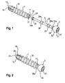
- shows a perspective exploded view of the bone anchor according to a first embodiment.
- Fig. 2:
- shows a perspective view of the bone anchor according to
Fig. 1 in an assembled state. - Fig. 3:
- shows a top view of the first end of the anchor member.
- Fig. 4:
- shows a side view of the anchor member.
- Fig. 5:
- shows a cross-sectional view of the anchor member according to line A-A in
Fig. 4 . - Fig. 6:
- shows a perspective view of the core member of the bone anchor according to the first embodiment.
- Fig. 7:
- shows a top view of the first end of the core member of the bone anchor according to the first embodiment.
- Fig. 8:
- shows a cross-sectional view of the core member of
Fig. 6 wherein the section has been taken in a plane containing the longitudinal axis. - Fig. 9:
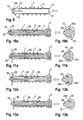
- shows a cross-sectional view of the anchor member of the bone anchor according to the first embodiment in a first step of anchoring the bone anchor in the bone.
- Fig. 10a:
- shows a cross-sectional view of mounting the core member to the anchor member inserted into the bone.
- Fig. 10b:
- shows an enlarged portion of
Fig. 10a . - Fig. 11a:
- shows a cross-sectional view of further inserting the core member to the anchor member while the anchor member is expanded.
- Fig. 11b:
- shows an enlarged portion of
Fig. 11a . - Fig. 12a:
- shows a still further step of inserting the core member while further expanding the anchor member.
- Fig. 12b:
- shows an enlarged portion of
Fig. 12a . - Fig. 13a:
- shows a cross-sectional view of the last step of connecting the core member to the anchor member wherein the core member is fully inserted into the anchor member.
- Fig. 13b:
- shows an enlarged portion of
Fig. 13a . - Figs. 14 to 16:
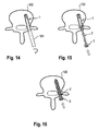
- show steps of anchoring the bone anchor according to the first embodiment in a pedicle of a vertebra.
- Fig. 17:
- shows a cross-section view of a polyaxial bone anchoring device with a bone anchor according to the first embodiment.
- Fig. 18:
- shows a cross-sectional view of a bone plate with the bone anchor according to the first embodiment.
- Fig. 19:
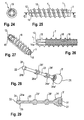
- shows a perspective exploded view of the bone anchor according to a second embodiment.
- Fig. 20:
- shows a perspective view of the bone anchor according to the second embodiment in an assembled state.
- Fig. 21:
- shows a side view of the bone anchor according to the second embodiment.
- Fig. 22:
- shows a cross-sectional view of the bone anchor according to the second embodiment along line B-B in
Fig. 21 . - Fig. 23:
- shows a bottom view of the second end of the bone anchor according to the second embodiment.
- Fig. 24:
- shows a top view of the first end of the anchor member of the bone anchor according to the second embodiment.
- Fig. 25:
- shows a side view of the anchor member according to the second embodiment.
- Fig. 26:
- shows a cross-sectional view of the anchor member according to the second embodiment along line C-C in
Fig. 25 . - Fig. 27:
- shows a perspective view from the first end of the anchor member according to the second embodiment.
- Fig. 28:
- shows a perspective view of the core member of the bone anchor according to the second embodiment.
- Fig. 29:
- shows a cross-section view of the core member according to the second embodiment, the section being taken in a plane containing the longitudinal axis.
- As shown in
Figs. 1 and 2 , the bone anchor according to a first embodiment comprises ananchor member 1, in the form of a screw member and acore member 2. Thecore member 2 can be inserted into theanchor member 1 and connected thereto to form the bone anchor. - As further shown in
Figs. 3 to 5 , theanchor member 1 has afirst end 11, an oppositesecond end 12 and a longitudinal axis L extending through thefirst end 11 and thesecond end 12. The anchor member is formed as a tubular member and has afirst section 13 with a first inner diameter, the first section extending from thefirst end 11 to a distance from thesecond end 12. In asecond section 14 adjacent thesecond end 12, the inner diameter is gradually reduced towards thesecond end 12. Thesecond section 14 comprises a taperedinner surface 14a tapering towards thesecond end 12. At thesecond end 12, at least two, preferably three or fourslits 15 are provided that are open to thesecond end 12 and extend into thefirst section 13. Theslits 15 are substantially parallel to the longitudinal axis L. By means of theslits 15, theanchor member 1 is rendered flexible in the region of itssecond end 12 as described below. - The front face of the
second end 12 defines an abutment for a portion of the core member when the core member is fully inserted as shown inFigs. 1 and13a, 13b. - At least a portion of the outer surface on the
anchor member 1 is provided with abone thread 16. Instead of thebone thread 16, another bone engagement structure may be provided, such as, for example, barbs or a textured surface. - At the
first end 11, a plurality ofrecesses 17 are extending from the front face of thefirst end 11 into the firsttubular section 13 and form engagement portions for a form-fit engagement with thehead 3. - The
anchor member 1 is made of a material that has a smaller modulus of elasticity compared to a modulus of elasticity of the material of thecore member 2. Preferably, theanchor member 1 is made of a polymer material, in particular a biocompatible polymer material. For example, the material may be selected from the group of polyaryletherketones PAEK including polyetheretherketone PEEK, polyetherketoneketone PEKK and polyetherketone PEK. However, other polymeric materials may also be used. The extent to which theanchor member 1 is expendable at its second end 1a can be adjusted during manufacturing by selecting an appropriate material, the wall thickness of theanchor member 1, the length and the width of theslits 15. - As further shown in
Figs. 6 to 8 , thecore member 2 comprises afirst end 21, an oppositesecond end 22 and a substantially rod-shapedcentral portion 23. Adjacent to thefirst end 21, ahead 3 of the anchor is provided. Thehead 3 has anengagement portion 31 at the free end that forms thefirst end 21 with a recess that can be engaged with a tool, such as a torx-shaped recess or a hexagon-shaped recess. Thehead 3 further comprises a spherically- shapedsurface portion 32. The diameter of the spherically-shapedsurface portion 32 decreases towards the rod-shapedcentral portion 23. Thehead 3 serves for connecting the bone anchor with other devices, such as stabilization or fixation devices, for example with a receiving part of a polyaxial bone anchor or with a plate member. Between the spherically-shapedouter surface portion 32 and the rod-shapedcentral portion 23, aneck portion 34 is provided that has a smaller diameter than the spherically-shaped outer surface portion and a larger diameter than the rod-shapedcentral portion 23. Theneck portion 34 has an outer diameter so that it fits into thetubular anchor member 1 at thefirst end 11.Projections 34a projecting in a radial direction and axial direction are present on positions corresponding to therecesses 17 at thefirst end 11 of theanchor member 1. Theprojections 34a are configured to engage therecesses 17 and achieve in a form-fit connection between thecore member 2 and theanchor member 1 at thefirst end 11 of theanchor member 1. By means of the engagement of theprojections 34a and therecesses 17, thecore member 2 can be fixed to theanchor member 1 so that thecore member 2 cannot rotate with respect to the anchor member. - At the
second end 22, thecore member 2 comprises atip 24. Thetip 24 tapers with a cone angle towards thesecond end 22 wherein the cone angle corresponds substantially to the cone angle of the taperedportion 14a of theanchor member 1. Between the rod-shapedcentral portion 23 and thetip 24, acylindrical portion 25 is present that has a smaller diameter than a base of thetip 24a such that, as can be seen inFig. 2 , thebase 24a of thetip 24 abuts against the front face of the second end of theanchor member 1. - One ore
more guide portions 26 may be provided on the rod-shapedcentral portion 23, wherein theguide portions 26 have a substantially cylindrical shape with aslanted surface 26a that tapers towards thesecond end 22. The outer diameter of theguide portions 26 is only slightly smaller than the inner diameter of thefirst section 13 of theanchor member 1. Therefore, theguide portions 26 provide guidance by sliding along the inner wall of theanchor member 1 when thecore member 2 is inserted into thetubular anchor member 1. The tapered surfaces 26a facilitate the insertion of thecore member 2 into theanchor member 1. Theguide portions 26 may be monolithically formed with thecore member 2 or may be separate parts that are fixed to thecore member 2. They may also be omitted. - The
core member 2 is made of a material that is preferably stiffer than the material of the anchor member, i.e. has a higher modulus of elasticity. For example, thecore member 2 is made of a metallic material such as titanium, stainless steel, a body compatible metal alloy, such as, for example, a Mi-Ti alloy, such as Nitinol. - A first embodiment of a method of using the anchor member will be explained with reference to
Figs. 9 to 13b . First, as shown inFig. 14 , the anchor member is inserted into a bone, a bone part or a vertebra (not shown). A core hole may be prepared in advance. A tool not shown may be used that engages the anchor member. Theengagement portion 17 that serves for a form-fit connection to theanchor member 1 may also be used as an engagement portion for a tool. Other engagement portions (not shown) may be provided. - In a second step, as shown in
Figs. 10a and 10b , thecore member 2 is inserted with thetip 24 facing theanchor member 1 into the anchor member until thetip 24 abuts against the taperedportion 14a on the inner wall of the anchor member at thesecond end 12. During insertion, thecore member 2 slides along the inner surface of theanchor member 1 while it is guided by the inner wall contacting theguide portions 26. - Next, as shown in
Figs. 11a and 11b , further advancement of thecore member 2 into theanchor member 1 results in an expansion of the anchor member at thesecond end 2 because the outer diameter of thebase 24a of thetip 24 is greater than the inner diameter of the tubular anchor member at the second end. - In a step, as shown in
Figs. 12a and 12b , the further advancement of the core member into theanchor member 2 allows thetip 24 to exit from theanchor member 2, thereby further expanding theanchor member 2 at thesecond end 12. - Finally, as shown in
Figs.13a and 13b , when thecore member 2 is still further advanced, the expanded portion of the anchor member snaps back so that the anchor member abuts with its front face at thesecond end 12 against thebase surface 24a of the tip with thecylindrical portion 25 extending through the second end and forming an abutment for the anchor member in radial direction. Thebase surface 24a of the tip forms an abutment in longitudinal direction for thesecond end 12 of the anchor member. The dimension of the rod-shapedcentral portion 23 is such that in the fully inserted configuration as shown inFig. 13a , theprojections 34a of thehead 3 fully engage therecesses 17 so that thecore 2 is rotationally fixed with respect to theanchor member 1. -
Figs. 14 to 16 show a method of use as described before with the application of the bone anchor to the pedicle of avertebra 100.Fig. 14 shows the anchor member being first inserted with atool 101 into a pedicle. Then, the tool is removed and the core member is inserted as shown inFig. 15. Fig. 16 shows the final configuration where thecore member 2 has been fully inserted into theanchor member 1. - In a second embodiment of a method of use the pre-assembled anchor member with the core member as depicted in
Fig. 13a are inserted as a whole assembly into the bone. - A first application of the bone anchor together with a stabilization device is shown in
Fig. 17 . The bone anchor according to the first embodiment is received in a receivingpart 4 of a polyaxial bone anchor. The receivingpart 4 is substantially cylindrical and comprises atop end 41, abottom end 42 and acoaxial bore 43 extending from the top end to a distance from the bottom end. Thebore 43 narrows towards thebottom end 42 and provides anopening 44. Near the bottom end, aseat 45 is provided for pivot ably receiving thehead 3. A U-shaped recess extends from the top end to a distance from the top end for receiving arod 5. By means of the U-shaped recess twofree legs internal thread 48 for cooperating with a lockingmember 6. Further, apressure member 7 is provided that exerts pressure onto thehead 3 such that thehead 3 can be locked in a certain angular position by tightening the locking member. The bone anchor may be used with other parts of receiving parts and designs for polyaxial bone screws. Also thehead 3 of thecore member 2 may be designed such that it comprises a section for receiving a rod and for receiving a locking member to fix the rod as known from monoaxial bone screws. - A second example of application is shown in
Fig. 18 wherein the bone anchors according to the first embodiment are used together with abone plate 9 that hasholes 10 andseat portions 11 for receiving thehead 3 of each bone anchor. Various configurations of such bone plates are conceivable. Also in this case, thehead 3 may be adapted in its shape to correspond to receiving portions provided in the bone plate. - Referring to
Figs. 19 to 21 , a second embodiment of the bone anchor is shown. The anchor member 1' and the core member 2' each comprise structures that cooperate which each other to enhance the fixation of the core member 2' to prevent a rotational and axial movement of the parts. - The anchor member 1' will be described more in detail with reference to
Figs. 24 to 27 . Parts and portions that are identical to the parts and portions of the previous embodiment are indicated with the same reference numerals and the description thereof will not be repeated. The anchor member 1' comprises an internal guiding structure provided by longitudinally extending rib-like projections 18. The rib-like projections 18 extend from thefirst end 11 to a distance from thesecond end 12. Preferably, the rib-like projections 18 extend only up to the end of theslits 15 so that the flexible portion of the anchor member does not have rib-like projections. - For example, four rib-
like projections 18 are arranged at substantially 90° with respect to each other so that they form a cross arrangement. In addition, at thesecond end 12, a plurality ofrecesses 19, for example four, are arranged in the end face of theend 12. Therecesses 19 serve for engagement with corresponding portions on the core member 2'. Thehead 3 has at its side facing the rod-shapedportion 23projections 34a' that are arranged and configured to engage thetubular section 13 that has the rib-like projections 18. - The core member 2' has on its rod-shaped
central portion 23 at least one, preferably a plurality of spaced apart guiding portions 26'. The maximum outer diameter of the guiding portion 26' is slightly smaller than the inner diameter of the anchor member 2' in the space between the rib-like projections 18. The guiding members 26' compriselongitudinal grooves 26a' that are arranged spaced apart form each other in a circumferential direction and at positions corresponding to the positions of theprojections 18. Hence, thegrooves 26a' are configured to be engaged with the rib-like projections 18. - At the base of the
tip 24 facing towards thefirst end 22, there areprojections 24b projecting outward and in the direction towards thefirst end 21 of the core member 2'. Theprojections 24b are configured to engage in therecesses 19 of the anchor member. - By means of the above described form-fit connection between the core member 2' and the anchor member 1' a structure is provided that prevents rotation of the core member 2' relative to the anchor member 1' and also prevents axial displacement of the members.
- Other designs of such engagement structures are possible. For example, more or less than four projections and grooves can be provided. The inner wall of the anchor member can have an elliptic or another contour that prevents rotation when engaging a corresponding contour of the core member 2'.
- Further modifications of the embodiments are possible. For example, the core member can be made of two or more parts. The head can be made as a separate part that can be connected to the core member. Also, the
head 3 may be a part of the anchor member. - The second end of the anchor member may be closed and a tip at the core member may be omitted. In this case, the structure is provided that fixes the core member to the anchor member.
- The head may have a different shape dependent of the intended use of the bone anchor. The materials and the combination of materials of the second embodiment may be the same as in the first embodiment.
Claims (16)
- Bone anchor comprising
an anchor member (1, 1') having an open first end (11) and a second end (12) and a tubular section (13) between the first end (11) and the second end (12), a longitudinal axis (L) extending from the first end to the second end, and a bone engagement structure (16) for engaging the bone in at least a portion of the tubular section (13);
wherein the anchor member (1) is made of a first material;
a core member (2, 2') having a first end (21) and a second end (22) and being insertable into the anchor member and connectable thereto ;
wherein the core member (2) is made of a second material that is different from the first material. - The bone anchor of claim 1, wherein the first material is a material that exhibits greater flexibility than the second material.
- The bone anchor of claim 1 or 2, wherein the first material is a polymeric material.
- The bone anchor of one of claims 1 to 3, wherein the second material is a metallic material.
- The bone anchor of one of claims 1 to 4, wherein the bone engagement structure (16) is a bone thread.
- The bone anchor of one of claims 1 to 5, wherein the first end (11) and the second end (12) of the bone anchor (1, 1') form the open ends of the tubular section (13) and wherein the anchor member (1, 1') is expandable at the second end (12).
- The bone anchor of one of claims 1 to 6, wherein the anchor member (1, 1') comprises at least two slits (15) extending substantially parallel to the longitudinal axis and being open to the second end (12).
- The bone anchor of one of claims 1 to 7, wherein the anchor member comprises a tapered section (14a) at the inner wall at or near the second end (12) that tapers towards the second end (12).
- The bone anchor of one of claims 1 to 8, wherein the anchor member (1, 1') comprises an engagement structure (17) at or near the first end (11) preferably in the form of at least one recess extending from a front face of the first end (11) into the tubular section (13).
- The bone anchor of one of claims 1 to 9, wherein the core member (2, 2') comprises a head (3, 3') at the first end, the head (3, 3') preferably having a spherically-shaped outer surface portion (32).
- The bone anchor of claim 10, wherein the head (3, 3') comprises an engagement portion (34) for engaging the anchor member (1, 1').
- The bone anchor of one of claims 1 to 11, wherein the core member (2, 2') comprises a tip (24) at the second end (12), the tip tapering towards the second end.
- The bone anchor of claim 12, wherein a maximum outer diameter of the tip (24) is greater than an inner diameter of a tubular section (14) at the second end (12).
- The bone anchor of one of claims 1 to 13, wherein the core member (2) comprises an abutment portion (24a) that cooperates with an abutment portion (12) of the anchor member (1) to prevent a movement of the core member (2) towards the first end (11).
- The bone anchor of one of claims 1 to 14, wherein an inner wall of the tubular section (13) of the anchor member (1') has a contour (18) that cooperates with a corresponding contour (26a) of the core member (2') in such a manner that a rotation of the core member (2') is prevented.
- The bone anchor of one of claims 1 to 15, wherein the inner wall of the tubular section comprises at least one longitudinally extending projection (18) and the core member comprises at least one corresponding longitudinal groove (26a').
Priority Applications (7)
| Application Number | Priority Date | Filing Date | Title |
|---|---|---|---|
| ES12172417.3T ES2563758T3 (en) | 2012-06-18 | 2012-06-18 | Bone anchor |
| EP12172417.3A EP2676622B1 (en) | 2012-06-18 | 2012-06-18 | Bone anchor |
| CN201310231498.8A CN103505277B (en) | 2012-06-18 | 2013-06-13 | Bone anchor assembly |
| TW102120828A TW201400082A (en) | 2012-06-18 | 2013-06-13 | Bone anchor |
| JP2013124503A JP6230283B2 (en) | 2012-06-18 | 2013-06-13 | Bone anchor |
| KR1020130067979A KR20130142075A (en) | 2012-06-18 | 2013-06-13 | Bone anchor |
| US13/919,966 US10010361B2 (en) | 2012-06-18 | 2013-06-17 | Bone anchor |
Applications Claiming Priority (1)
| Application Number | Priority Date | Filing Date | Title |
|---|---|---|---|
| EP12172417.3A EP2676622B1 (en) | 2012-06-18 | 2012-06-18 | Bone anchor |
Publications (2)
| Publication Number | Publication Date |
|---|---|
| EP2676622A1 true EP2676622A1 (en) | 2013-12-25 |
| EP2676622B1 EP2676622B1 (en) | 2015-12-30 |
Family
ID=46331044
Family Applications (1)
| Application Number | Title | Priority Date | Filing Date |
|---|---|---|---|
| EP12172417.3A Active EP2676622B1 (en) | 2012-06-18 | 2012-06-18 | Bone anchor |
Country Status (7)
| Country | Link |
|---|---|
| US (1) | US10010361B2 (en) |
| EP (1) | EP2676622B1 (en) |
| JP (1) | JP6230283B2 (en) |
| KR (1) | KR20130142075A (en) |
| CN (1) | CN103505277B (en) |
| ES (1) | ES2563758T3 (en) |
| TW (1) | TW201400082A (en) |
Cited By (2)
| Publication number | Priority date | Publication date | Assignee | Title |
|---|---|---|---|---|
| WO2018130877A1 (en) * | 2017-01-11 | 2018-07-19 | Apifix Ltd. | Spinal screw with movable tip |
| EP3781056A4 (en) * | 2018-06-26 | 2022-01-26 | Integrity Implants Inc. | Length adjustable modular screw system |
Families Citing this family (32)
| Publication number | Priority date | Publication date | Assignee | Title |
|---|---|---|---|---|
| US4770858A (en) * | 1987-04-17 | 1988-09-13 | Pillar Technologies, Inc. | Resilient dielectric electrode for corona discharge devices |
| KR101570213B1 (en) | 2007-12-17 | 2015-11-18 | 신세스 게엠바하 | Dynamic bone fixation element and method of using the same |
| US10363140B2 (en) | 2012-03-09 | 2019-07-30 | Si-Bone Inc. | Systems, device, and methods for joint fusion |
| EP3335655B1 (en) * | 2012-03-13 | 2019-07-24 | Synthes GmbH | Dynamic bone fixation element |
| US20140277530A1 (en) | 2013-03-15 | 2014-09-18 | Smed-Ta/Td, Llc | Fixation of bone implants |
| CA2904717C (en) * | 2013-03-15 | 2021-05-11 | Malcolm Heaven | System and method for securing tissue to bone |
| US11147688B2 (en) | 2013-10-15 | 2021-10-19 | Si-Bone Inc. | Implant placement |
| EP2932929B1 (en) * | 2014-04-15 | 2017-02-08 | Biedermann Technologies GmbH & Co. KG | A screw element for use in spinal, orthopedic or trauma surgery and a system of such a screw element and a screw driver adapted thereto |
| US10166033B2 (en) | 2014-09-18 | 2019-01-01 | Si-Bone Inc. | Implants for bone fixation or fusion |
| EP3193752B1 (en) | 2014-09-18 | 2020-07-22 | SI-Bone, Inc. | Matrix implant |
| CH710695B1 (en) * | 2015-02-03 | 2022-11-30 | Brianza Stefano | Device for variable fixation of bone fragments. |
| WO2016145437A1 (en) * | 2015-03-12 | 2016-09-15 | Spinal Balance, Inc. | Pedicle reconstruction device |
| EP3093030A1 (en) * | 2015-05-12 | 2016-11-16 | Biotronik AG | Bioabsorbable osteosynthesis implant |
| AU2016247221B2 (en) * | 2015-10-23 | 2021-03-11 | K2M, Inc. | Semi-constrained bone screw and insertion instrument |
| WO2017189716A1 (en) * | 2016-04-26 | 2017-11-02 | K2M, Inc. | Expandable surgical fixation assemblies and method of use |
| US10485596B2 (en) * | 2016-12-06 | 2019-11-26 | Medos International Sàrl | Longitudinally-adjustable bone anchors and related methods |
| CN106691559A (en) * | 2016-12-20 | 2017-05-24 | 刘彬 | Orthopedics department locking screw |
| US10172656B1 (en) * | 2017-09-15 | 2019-01-08 | Alphatec Spine, Inc. | Surgical screw |
| US20190298528A1 (en) | 2018-03-28 | 2019-10-03 | Derek P. LINDSEY | Threaded implants and methods of use across bone segments |
| US20220000529A1 (en) * | 2018-11-16 | 2022-01-06 | Indian Institute Of Technology Delhi | Orthopedic screw |
| EP4613244A3 (en) * | 2019-02-14 | 2025-11-12 | SI-Bone Inc. | Implants for spinal fixation and or fusion |
| US11020154B2 (en) * | 2019-04-26 | 2021-06-01 | Warsaw Orthopedic, Inc. | Surgical instrument and methods of use |
| AU2020386985A1 (en) | 2019-11-21 | 2022-06-02 | Si-Bone Inc. | Rod coupling assemblies for bone stabilization constructs |
| WO2021108590A1 (en) | 2019-11-27 | 2021-06-03 | Si-Bone, Inc. | Bone stabilizing implants and methods of placement across si joints |
| JP2023504571A (en) | 2019-12-09 | 2023-02-03 | エスアイ-ボーン・インコーポレイテッド | Sacroiliac joint stabilization implant and implantation method |
| AU2021201202B2 (en) * | 2020-03-23 | 2026-02-19 | Smith & Nephew Asia Pacific Pte. Limited | Anchor delivery systems |
| KR102492061B1 (en) * | 2020-06-15 | 2023-01-25 | 충남대학교산학협력단 | Cortical screw reinforcement structure for bone fixation, cortical screw module having the same, inserting method of cortical screw module |
| JP2023553120A (en) | 2020-12-09 | 2023-12-20 | エスアイ-ボーン・インコーポレイテッド | Sacroiliac joint stabilization implants and implant methods |
| WO2023102533A1 (en) | 2021-12-03 | 2023-06-08 | Si-Bone Inc. | Fusion cages and methods for sacro-iliac joint stabilization |
| AU2024325368A1 (en) | 2023-08-15 | 2026-03-12 | Si-Bone Inc. | Pelvic stabilization implants, methods of use and manufacture |
| US20250099148A1 (en) * | 2023-09-21 | 2025-03-27 | Howmedica Osteonics Corp. | Heat Resistant Bone Screw |
| US12661159B1 (en) | 2025-07-17 | 2026-06-23 | Genesys Orthopedic Systems, L.L.C. | Orthopedic anchor system |
Citations (8)
| Publication number | Priority date | Publication date | Assignee | Title |
|---|---|---|---|---|
| WO1995015726A1 (en) * | 1993-12-06 | 1995-06-15 | Innovasive Devices, Inc. | Bone fastener |
| US6168597B1 (en) | 1996-02-28 | 2001-01-02 | Lutz Biedermann | Bone screw |
| EP1743587A1 (en) * | 2005-07-08 | 2007-01-17 | BIEDERMANN MOTECH GmbH | Bone anchoring element |
| WO2008004057A2 (en) * | 2006-07-05 | 2008-01-10 | Implants International Limited | Bone screw |
| WO2008024373A2 (en) * | 2006-08-21 | 2008-02-28 | Abdou M Samy | Bone screw systems and methods of use |
| WO2009120969A2 (en) * | 2008-03-28 | 2009-10-01 | Osteotech, Inc. | Bone anchors for orthopedic applications |
| US20100082071A1 (en) | 2008-09-26 | 2010-04-01 | Missoum Moumene | Composite Screw Having A Metallic Pin and a Polymeric Thread |
| US20120078369A1 (en) * | 1996-11-21 | 2012-03-29 | Depuy Mitek, Inc. | Method of anchoring autologous or artificial tendon grafts in bone |
Family Cites Families (34)
| Publication number | Priority date | Publication date | Assignee | Title |
|---|---|---|---|---|
| DE3811345C1 (en) | 1988-04-02 | 1989-09-07 | Aesculap Ag, 7200 Tuttlingen, De | |
| US5061137A (en) | 1991-04-29 | 1991-10-29 | Ford Motor Company | Fastener with resilient linking means |
| US5380334A (en) | 1993-02-17 | 1995-01-10 | Smith & Nephew Dyonics, Inc. | Soft tissue anchors and systems for implantation |
| US5584695A (en) | 1994-03-07 | 1996-12-17 | Memory Medical Systems, Inc. | Bone anchoring apparatus and method |
| IL121316A (en) | 1997-07-15 | 2001-07-24 | Litana Ltd | Implantable medical device of shape memory alloy |
| CN2453859Y (en) | 2000-12-11 | 2001-10-17 | 兰州西脉记忆合金股份有限公司 | Internal fixation brne nail |
| US7235079B2 (en) | 2004-11-18 | 2007-06-26 | Acumed Llc | Composite bone fasteners |
| US7066937B2 (en) | 2002-02-13 | 2006-06-27 | Endius Incorporated | Apparatus for connecting a longitudinal member to a bone portion |
| US6610018B1 (en) | 2002-02-14 | 2003-08-26 | Mcintyre Kevin M. | Non-invasive determination of left-ventricular pressure |
| US8348982B2 (en) | 2003-04-21 | 2013-01-08 | Atlas Spine, Inc. | Bone fixation plate |
| US20060264954A1 (en) | 2005-04-07 | 2006-11-23 | Sweeney Thomas M Ii | Active compression screw system and method for using the same |
| KR101145415B1 (en) | 2005-07-08 | 2012-05-15 | 비이더만 모테크 게엠베하 & 코. 카게 | Bone Anchoring Element |
| EP1749490B1 (en) | 2005-08-05 | 2008-11-19 | BIEDERMANN MOTECH GmbH | Bone anchoring element |
| US7850717B2 (en) | 2006-03-01 | 2010-12-14 | Warsaw Orthopedic, Inc. | Bone anchors having two or more portions exhibiting different performance characteristics and method of forming the same |
| WO2007110863A2 (en) | 2006-03-24 | 2007-10-04 | Yosef Freedland | Curved wall fasteners |
| CN101484079A (en) | 2006-05-12 | 2009-07-15 | 科迪斯公司 | Bone anchor system and method of use |
| CA2660141A1 (en) | 2006-08-07 | 2008-02-14 | Francois Cardarelli | Composite metallic materials, uses thereof and process for making same |
| EP2129329A2 (en) | 2007-03-07 | 2009-12-09 | Spinealign Medical, Inc. | Systems, methods, and devices for soft tissue attachment to bone |
| EP2974672B1 (en) | 2007-11-02 | 2019-12-04 | Stout Medical Group, L.P. | Expandable attachment device |
| KR101570213B1 (en) | 2007-12-17 | 2015-11-18 | 신세스 게엠바하 | Dynamic bone fixation element and method of using the same |
| US20100076498A1 (en) | 2008-06-10 | 2010-03-25 | Jeff Tyber | Active compression orthopedic screw assembly and method of use |
| US20100228301A1 (en) | 2009-03-09 | 2010-09-09 | Greenhalgh E Skott | Attachment device and methods of use |
| CN102413777B (en) * | 2009-03-12 | 2014-07-16 | 扩张整形外科公司 | Bone implantation and stabilization assembly including deployment device |
| BRPI1014714B1 (en) * | 2009-07-06 | 2020-05-19 | Synthes Gmbh | expandable bone fixation set |
| US9050153B2 (en) | 2009-11-05 | 2015-06-09 | The Johns Hopkins University | Universally deployable and expandable bone screw anchor |
| DE112010005201B4 (en) | 2010-01-28 | 2025-10-16 | Tohoku University | Manufacturing processes for metallic parts and the metallic part |
| US20120010668A1 (en) * | 2010-07-08 | 2012-01-12 | Warsaw Orthopedic, Inc. | Expandable surgical implant |
| ES2564415T3 (en) | 2010-10-26 | 2016-03-22 | Christian Röbling | Device to stabilize a spine |
| WO2012097326A2 (en) | 2011-01-14 | 2012-07-19 | Alphatec Spine, Inc. | Expandable facet screw |
| WO2012129183A1 (en) | 2011-03-21 | 2012-09-27 | Ronald Childs | Sleeve for bone fixation device |
| EP3335655B1 (en) | 2012-03-13 | 2019-07-24 | Synthes GmbH | Dynamic bone fixation element |
| JP2014110486A (en) | 2012-11-30 | 2014-06-12 | Canon Marketing Japan Inc | Information processing unit, information processing method, program, and information processing system |
| EP2740427B1 (en) | 2012-12-05 | 2020-03-11 | Biedermann Technologies GmbH & Co. KG | Dynamic bone anchor and method of manufacturing the same |
| EP2740428B1 (en) | 2012-12-05 | 2019-05-08 | Biedermann Technologies GmbH & Co. KG | Dynamic bone anchor and method of manufacturing a dynamic bone anchor |
-
2012
- 2012-06-18 ES ES12172417.3T patent/ES2563758T3/en active Active
- 2012-06-18 EP EP12172417.3A patent/EP2676622B1/en active Active
-
2013
- 2013-06-13 JP JP2013124503A patent/JP6230283B2/en not_active Expired - Fee Related
- 2013-06-13 CN CN201310231498.8A patent/CN103505277B/en not_active Expired - Fee Related
- 2013-06-13 TW TW102120828A patent/TW201400082A/en unknown
- 2013-06-13 KR KR1020130067979A patent/KR20130142075A/en not_active Ceased
- 2013-06-17 US US13/919,966 patent/US10010361B2/en active Active
Patent Citations (8)
| Publication number | Priority date | Publication date | Assignee | Title |
|---|---|---|---|---|
| WO1995015726A1 (en) * | 1993-12-06 | 1995-06-15 | Innovasive Devices, Inc. | Bone fastener |
| US6168597B1 (en) | 1996-02-28 | 2001-01-02 | Lutz Biedermann | Bone screw |
| US20120078369A1 (en) * | 1996-11-21 | 2012-03-29 | Depuy Mitek, Inc. | Method of anchoring autologous or artificial tendon grafts in bone |
| EP1743587A1 (en) * | 2005-07-08 | 2007-01-17 | BIEDERMANN MOTECH GmbH | Bone anchoring element |
| WO2008004057A2 (en) * | 2006-07-05 | 2008-01-10 | Implants International Limited | Bone screw |
| WO2008024373A2 (en) * | 2006-08-21 | 2008-02-28 | Abdou M Samy | Bone screw systems and methods of use |
| WO2009120969A2 (en) * | 2008-03-28 | 2009-10-01 | Osteotech, Inc. | Bone anchors for orthopedic applications |
| US20100082071A1 (en) | 2008-09-26 | 2010-04-01 | Missoum Moumene | Composite Screw Having A Metallic Pin and a Polymeric Thread |
Cited By (5)
| Publication number | Priority date | Publication date | Assignee | Title |
|---|---|---|---|---|
| WO2018130877A1 (en) * | 2017-01-11 | 2018-07-19 | Apifix Ltd. | Spinal screw with movable tip |
| US11364060B2 (en) | 2017-01-11 | 2022-06-21 | Apifix Ltd | Spinal screw with movable tip |
| JP2023030181A (en) * | 2017-01-11 | 2023-03-07 | アピフィックス・リミテッド | Spinal screw with movable tip |
| EP4193942A1 (en) * | 2017-01-11 | 2023-06-14 | Apifix Ltd. | Spinal screw with movable tip |
| EP3781056A4 (en) * | 2018-06-26 | 2022-01-26 | Integrity Implants Inc. | Length adjustable modular screw system |
Also Published As
| Publication number | Publication date |
|---|---|
| JP6230283B2 (en) | 2017-11-15 |
| US10010361B2 (en) | 2018-07-03 |
| US20140005731A1 (en) | 2014-01-02 |
| CN103505277A (en) | 2014-01-15 |
| TW201400082A (en) | 2014-01-01 |
| KR20130142075A (en) | 2013-12-27 |
| JP2014000402A (en) | 2014-01-09 |
| CN103505277B (en) | 2017-08-25 |
| ES2563758T3 (en) | 2016-03-16 |
| EP2676622B1 (en) | 2015-12-30 |
Similar Documents
| Publication | Publication Date | Title |
|---|---|---|
| EP2676622B1 (en) | Bone anchor | |
| US12042195B2 (en) | Bone anchor | |
| EP2570090B1 (en) | Polyaxial bone anchoring device with enlarged pivot angle | |
| US10335215B2 (en) | Bone screw with self-constrained flexibility | |
| EP2586392B1 (en) | High angulation polyaxial bone anchoring device | |
| EP2749239B1 (en) | Dynamic bone anchor | |
| EP3269321A1 (en) | Instrument for holding and inserting a bone anchor | |
| EP2740428A1 (en) | Dynamic bone anchor and method of manufacturing a dynamic bone anchor | |
| EP2881053A1 (en) | Extension device for a bone anchor, in particular for minimally invasive surgery | |
| EP2772212B1 (en) | Instrument for inserting a bone anchoring element and system of such an instrument and a polyaxial bone anchoring element | |
| EP2772216A1 (en) | Locking device for locking a rod-shaped element in a receiving part of a bone anchor and bone anchor with such a locking device | |
| EP2740424A1 (en) | Anchoring member suitable for use in a polyaxial bone anchoring device and polyaxial bone anchoring device with an enlarged pivot angle to one side | |
| EP2586391A1 (en) | A locking assembly for a polyaxial bone anchoring device | |
| EP2674123A1 (en) | Polyaxial bone anchoring device | |
| CN106236230B (en) | Receiving part of a bone anchoring device and bone anchoring device with such a receiving part |
Legal Events
| Date | Code | Title | Description |
|---|---|---|---|
| PUAI | Public reference made under article 153(3) epc to a published international application that has entered the european phase |
Free format text: ORIGINAL CODE: 0009012 |
|
| AK | Designated contracting states |
Kind code of ref document: A1 Designated state(s): AL AT BE BG CH CY CZ DE DK EE ES FI FR GB GR HR HU IE IS IT LI LT LU LV MC MK MT NL NO PL PT RO RS SE SI SK SM TR |
|
| AX | Request for extension of the european patent |
Extension state: BA ME |
|
| 17P | Request for examination filed |
Effective date: 20140625 |
|
| RBV | Designated contracting states (corrected) |
Designated state(s): AL AT BE BG CH CY CZ DE DK EE ES FI FR GB GR HR HU IE IS IT LI LT LU LV MC MK MT NL NO PL PT RO RS SE SI SK SM TR |
|
| 17Q | First examination report despatched |
Effective date: 20141028 |
|
| GRAP | Despatch of communication of intention to grant a patent |
Free format text: ORIGINAL CODE: EPIDOSNIGR1 |
|
| INTG | Intention to grant announced |
Effective date: 20150803 |
|
| GRAS | Grant fee paid |
Free format text: ORIGINAL CODE: EPIDOSNIGR3 |
|
| GRAA | (expected) grant |
Free format text: ORIGINAL CODE: 0009210 |
|
| AK | Designated contracting states |
Kind code of ref document: B1 Designated state(s): AL AT BE BG CH CY CZ DE DK EE ES FI FR GB GR HR HU IE IS IT LI LT LU LV MC MK MT NL NO PL PT RO RS SE SI SK SM TR |
|
| REG | Reference to a national code |
Ref country code: GB Ref legal event code: FG4D |
|
| REG | Reference to a national code |
Ref country code: CH Ref legal event code: EP |
|
| REG | Reference to a national code |
Ref country code: AT Ref legal event code: REF Ref document number: 767099 Country of ref document: AT Kind code of ref document: T Effective date: 20160115 Ref country code: CH Ref legal event code: NV Representative=s name: NOVAGRAAF INTERNATIONAL SA, CH |
|
| REG | Reference to a national code |
Ref country code: IE Ref legal event code: FG4D |
|
| REG | Reference to a national code |
Ref country code: DE Ref legal event code: R096 Ref document number: 602012013307 Country of ref document: DE |
|
| REG | Reference to a national code |
Ref country code: ES Ref legal event code: FG2A Ref document number: 2563758 Country of ref document: ES Kind code of ref document: T3 Effective date: 20160316 |
|
| REG | Reference to a national code |
Ref country code: LT Ref legal event code: MG4D |
|
| PG25 | Lapsed in a contracting state [announced via postgrant information from national office to epo] |
Ref country code: HR Free format text: LAPSE BECAUSE OF FAILURE TO SUBMIT A TRANSLATION OF THE DESCRIPTION OR TO PAY THE FEE WITHIN THE PRESCRIBED TIME-LIMIT Effective date: 20151230 Ref country code: LT Free format text: LAPSE BECAUSE OF FAILURE TO SUBMIT A TRANSLATION OF THE DESCRIPTION OR TO PAY THE FEE WITHIN THE PRESCRIBED TIME-LIMIT Effective date: 20151230 Ref country code: NO Free format text: LAPSE BECAUSE OF FAILURE TO SUBMIT A TRANSLATION OF THE DESCRIPTION OR TO PAY THE FEE WITHIN THE PRESCRIBED TIME-LIMIT Effective date: 20160330 |
|
| REG | Reference to a national code |
Ref country code: NL Ref legal event code: MP Effective date: 20151230 |
|
| REG | Reference to a national code |
Ref country code: AT Ref legal event code: MK05 Ref document number: 767099 Country of ref document: AT Kind code of ref document: T Effective date: 20151230 |
|
| PG25 | Lapsed in a contracting state [announced via postgrant information from national office to epo] |
Ref country code: RS Free format text: LAPSE BECAUSE OF FAILURE TO SUBMIT A TRANSLATION OF THE DESCRIPTION OR TO PAY THE FEE WITHIN THE PRESCRIBED TIME-LIMIT Effective date: 20151230 Ref country code: GR Free format text: LAPSE BECAUSE OF FAILURE TO SUBMIT A TRANSLATION OF THE DESCRIPTION OR TO PAY THE FEE WITHIN THE PRESCRIBED TIME-LIMIT Effective date: 20160331 Ref country code: LV Free format text: LAPSE BECAUSE OF FAILURE TO SUBMIT A TRANSLATION OF THE DESCRIPTION OR TO PAY THE FEE WITHIN THE PRESCRIBED TIME-LIMIT Effective date: 20151230 Ref country code: SE Free format text: LAPSE BECAUSE OF FAILURE TO SUBMIT A TRANSLATION OF THE DESCRIPTION OR TO PAY THE FEE WITHIN THE PRESCRIBED TIME-LIMIT Effective date: 20151230 Ref country code: FI Free format text: LAPSE BECAUSE OF FAILURE TO SUBMIT A TRANSLATION OF THE DESCRIPTION OR TO PAY THE FEE WITHIN THE PRESCRIBED TIME-LIMIT Effective date: 20151230 |
|
| REG | Reference to a national code |
Ref country code: FR Ref legal event code: PLFP Year of fee payment: 5 |
|
| PG25 | Lapsed in a contracting state [announced via postgrant information from national office to epo] |
Ref country code: NL Free format text: LAPSE BECAUSE OF FAILURE TO SUBMIT A TRANSLATION OF THE DESCRIPTION OR TO PAY THE FEE WITHIN THE PRESCRIBED TIME-LIMIT Effective date: 20151230 |
|
| PG25 | Lapsed in a contracting state [announced via postgrant information from national office to epo] |
Ref country code: CZ Free format text: LAPSE BECAUSE OF FAILURE TO SUBMIT A TRANSLATION OF THE DESCRIPTION OR TO PAY THE FEE WITHIN THE PRESCRIBED TIME-LIMIT Effective date: 20151230 |
|
| PGFP | Annual fee paid to national office [announced via postgrant information from national office to epo] |
Ref country code: ES Payment date: 20160622 Year of fee payment: 5 |
|
| PG25 | Lapsed in a contracting state [announced via postgrant information from national office to epo] |
Ref country code: SM Free format text: LAPSE BECAUSE OF FAILURE TO SUBMIT A TRANSLATION OF THE DESCRIPTION OR TO PAY THE FEE WITHIN THE PRESCRIBED TIME-LIMIT Effective date: 20151230 Ref country code: PL Free format text: LAPSE BECAUSE OF FAILURE TO SUBMIT A TRANSLATION OF THE DESCRIPTION OR TO PAY THE FEE WITHIN THE PRESCRIBED TIME-LIMIT Effective date: 20151230 Ref country code: EE Free format text: LAPSE BECAUSE OF FAILURE TO SUBMIT A TRANSLATION OF THE DESCRIPTION OR TO PAY THE FEE WITHIN THE PRESCRIBED TIME-LIMIT Effective date: 20151230 Ref country code: AT Free format text: LAPSE BECAUSE OF FAILURE TO SUBMIT A TRANSLATION OF THE DESCRIPTION OR TO PAY THE FEE WITHIN THE PRESCRIBED TIME-LIMIT Effective date: 20151230 Ref country code: SK Free format text: LAPSE BECAUSE OF FAILURE TO SUBMIT A TRANSLATION OF THE DESCRIPTION OR TO PAY THE FEE WITHIN THE PRESCRIBED TIME-LIMIT Effective date: 20151230 Ref country code: PT Free format text: LAPSE BECAUSE OF FAILURE TO SUBMIT A TRANSLATION OF THE DESCRIPTION OR TO PAY THE FEE WITHIN THE PRESCRIBED TIME-LIMIT Effective date: 20160502 Ref country code: IS Free format text: LAPSE BECAUSE OF FAILURE TO SUBMIT A TRANSLATION OF THE DESCRIPTION OR TO PAY THE FEE WITHIN THE PRESCRIBED TIME-LIMIT Effective date: 20160430 Ref country code: RO Free format text: LAPSE BECAUSE OF FAILURE TO SUBMIT A TRANSLATION OF THE DESCRIPTION OR TO PAY THE FEE WITHIN THE PRESCRIBED TIME-LIMIT Effective date: 20151230 |
|
| PGFP | Annual fee paid to national office [announced via postgrant information from national office to epo] |
Ref country code: FR Payment date: 20160621 Year of fee payment: 5 |
|
| REG | Reference to a national code |
Ref country code: DE Ref legal event code: R097 Ref document number: 602012013307 Country of ref document: DE |
|
| PG25 | Lapsed in a contracting state [announced via postgrant information from national office to epo] |
Ref country code: DK Free format text: LAPSE BECAUSE OF FAILURE TO SUBMIT A TRANSLATION OF THE DESCRIPTION OR TO PAY THE FEE WITHIN THE PRESCRIBED TIME-LIMIT Effective date: 20151230 |
|
| PGFP | Annual fee paid to national office [announced via postgrant information from national office to epo] |
Ref country code: IT Payment date: 20160628 Year of fee payment: 5 |
|
| PLBE | No opposition filed within time limit |
Free format text: ORIGINAL CODE: 0009261 |
|
| STAA | Information on the status of an ep patent application or granted ep patent |
Free format text: STATUS: NO OPPOSITION FILED WITHIN TIME LIMIT |
|
| 26N | No opposition filed |
Effective date: 20161003 |
|
| PG25 | Lapsed in a contracting state [announced via postgrant information from national office to epo] |
Ref country code: BE Free format text: LAPSE BECAUSE OF FAILURE TO SUBMIT A TRANSLATION OF THE DESCRIPTION OR TO PAY THE FEE WITHIN THE PRESCRIBED TIME-LIMIT Effective date: 20151230 |
|
| PG25 | Lapsed in a contracting state [announced via postgrant information from national office to epo] |
Ref country code: MC Free format text: LAPSE BECAUSE OF FAILURE TO SUBMIT A TRANSLATION OF THE DESCRIPTION OR TO PAY THE FEE WITHIN THE PRESCRIBED TIME-LIMIT Effective date: 20151230 |
|
| PG25 | Lapsed in a contracting state [announced via postgrant information from national office to epo] |
Ref country code: SI Free format text: LAPSE BECAUSE OF FAILURE TO SUBMIT A TRANSLATION OF THE DESCRIPTION OR TO PAY THE FEE WITHIN THE PRESCRIBED TIME-LIMIT Effective date: 20151230 |
|
| REG | Reference to a national code |
Ref country code: IE Ref legal event code: MM4A |
|
| PG25 | Lapsed in a contracting state [announced via postgrant information from national office to epo] |
Ref country code: IE Free format text: LAPSE BECAUSE OF NON-PAYMENT OF DUE FEES Effective date: 20160618 |
|
| REG | Reference to a national code |
Ref country code: FR Ref legal event code: ST Effective date: 20180228 |
|
| PG25 | Lapsed in a contracting state [announced via postgrant information from national office to epo] |
Ref country code: CY Free format text: LAPSE BECAUSE OF FAILURE TO SUBMIT A TRANSLATION OF THE DESCRIPTION OR TO PAY THE FEE WITHIN THE PRESCRIBED TIME-LIMIT Effective date: 20151230 Ref country code: FR Free format text: LAPSE BECAUSE OF NON-PAYMENT OF DUE FEES Effective date: 20170630 Ref country code: IT Free format text: LAPSE BECAUSE OF NON-PAYMENT OF DUE FEES Effective date: 20170618 Ref country code: HU Free format text: LAPSE BECAUSE OF FAILURE TO SUBMIT A TRANSLATION OF THE DESCRIPTION OR TO PAY THE FEE WITHIN THE PRESCRIBED TIME-LIMIT; INVALID AB INITIO Effective date: 20120618 |
|
| PG25 | Lapsed in a contracting state [announced via postgrant information from national office to epo] |
Ref country code: TR Free format text: LAPSE BECAUSE OF FAILURE TO SUBMIT A TRANSLATION OF THE DESCRIPTION OR TO PAY THE FEE WITHIN THE PRESCRIBED TIME-LIMIT Effective date: 20151230 Ref country code: MT Free format text: LAPSE BECAUSE OF NON-PAYMENT OF DUE FEES Effective date: 20160630 Ref country code: MK Free format text: LAPSE BECAUSE OF FAILURE TO SUBMIT A TRANSLATION OF THE DESCRIPTION OR TO PAY THE FEE WITHIN THE PRESCRIBED TIME-LIMIT Effective date: 20151230 Ref country code: LU Free format text: LAPSE BECAUSE OF NON-PAYMENT OF DUE FEES Effective date: 20160618 |
|
| PG25 | Lapsed in a contracting state [announced via postgrant information from national office to epo] |
Ref country code: BG Free format text: LAPSE BECAUSE OF FAILURE TO SUBMIT A TRANSLATION OF THE DESCRIPTION OR TO PAY THE FEE WITHIN THE PRESCRIBED TIME-LIMIT Effective date: 20151230 |
|
| REG | Reference to a national code |
Ref country code: ES Ref legal event code: FD2A Effective date: 20181026 |
|
| PG25 | Lapsed in a contracting state [announced via postgrant information from national office to epo] |
Ref country code: AL Free format text: LAPSE BECAUSE OF FAILURE TO SUBMIT A TRANSLATION OF THE DESCRIPTION OR TO PAY THE FEE WITHIN THE PRESCRIBED TIME-LIMIT Effective date: 20151230 |
|
| PG25 | Lapsed in a contracting state [announced via postgrant information from national office to epo] |
Ref country code: ES Free format text: LAPSE BECAUSE OF NON-PAYMENT OF DUE FEES Effective date: 20170619 |
|
| P01 | Opt-out of the competence of the unified patent court (upc) registered |
Effective date: 20230525 |
|
| PGFP | Annual fee paid to national office [announced via postgrant information from national office to epo] |
Ref country code: CH Payment date: 20250701 Year of fee payment: 14 |
|
| REG | Reference to a national code |
Ref country code: CH Ref legal event code: U11 Free format text: ST27 STATUS EVENT CODE: U-0-0-U10-U11 (AS PROVIDED BY THE NATIONAL OFFICE) Effective date: 20260701 |
|
| PGFP | Annual fee paid to national office [announced via postgrant information from national office to epo] |
Ref country code: GB Payment date: 20260611 Year of fee payment: 15 |
|
| PGFP | Annual fee paid to national office [announced via postgrant information from national office to epo] |
Ref country code: DE Payment date: 20260629 Year of fee payment: 15 |