EP2676618A1 - Veress needle - Google Patents
Veress needle Download PDFInfo
- Publication number
- EP2676618A1 EP2676618A1 EP11858968.8A EP11858968A EP2676618A1 EP 2676618 A1 EP2676618 A1 EP 2676618A1 EP 11858968 A EP11858968 A EP 11858968A EP 2676618 A1 EP2676618 A1 EP 2676618A1
- Authority
- EP
- European Patent Office
- Prior art keywords
- end portion
- insertion member
- puncturing
- proximal end
- distal end
- Prior art date
- Legal status (The legal status is an assumption and is not a legal conclusion. Google has not performed a legal analysis and makes no representation as to the accuracy of the status listed.)
- Withdrawn
Links
Images








Classifications
-
- A—HUMAN NECESSITIES
- A61—MEDICAL OR VETERINARY SCIENCE; HYGIENE
- A61B—DIAGNOSIS; SURGERY; IDENTIFICATION
- A61B17/00—Surgical instruments, devices or methods
- A61B17/34—Trocars; Puncturing needles
- A61B17/3474—Insufflating needles, e.g. Veress needles
-
- A—HUMAN NECESSITIES
- A61—MEDICAL OR VETERINARY SCIENCE; HYGIENE
- A61B—DIAGNOSIS; SURGERY; IDENTIFICATION
- A61B17/00—Surgical instruments, devices or methods
- A61B17/34—Trocars; Puncturing needles
- A61B17/3494—Trocars; Puncturing needles with safety means for protection against accidental cutting or pricking, e.g. limiting insertion depth, pressure sensors
- A61B17/3496—Protecting sleeves or inner probes; Retractable tips
-
- A—HUMAN NECESSITIES
- A61—MEDICAL OR VETERINARY SCIENCE; HYGIENE
- A61B—DIAGNOSIS; SURGERY; IDENTIFICATION
- A61B17/00—Surgical instruments, devices or methods
- A61B2017/00831—Material properties
- A61B2017/00867—Material properties shape memory effect
-
- A—HUMAN NECESSITIES
- A61—MEDICAL OR VETERINARY SCIENCE; HYGIENE
- A61B—DIAGNOSIS; SURGERY; IDENTIFICATION
- A61B17/00—Surgical instruments, devices or methods
- A61B17/34—Trocars; Puncturing needles
- A61B2017/348—Means for supporting the trocar against the body or retaining the trocar inside the body
- A61B2017/3482—Means for supporting the trocar against the body or retaining the trocar inside the body inside
- A61B2017/3484—Anchoring means, e.g. spreading-out umbrella-like structure
Definitions
- the present invention relates to a Veress needle.
- a Veress needle with a guarded needle tip is applied to prevent damages on organs positioned on an inner side of a puncturing site (see, for example, Patent Reference 1 and Patent Reference 2).
- the present invention is made in order to solve the abovementioned problem associated with the related art, and to provide a Veress needle which can easily prevent a needle tip from being pulled out from a puncturing site.
- a Veress needle comprising a hollow puncturing needle which comprises a distal end portion with a needle tip and a lumen, an insertion member which is slidably inserted in the lumen, an urging device, and a pullout preventing device.
- the urging device is adapted to urge the insertion member such that, before puncturing is performed by means of the needle tip and after the puncturing is completed, a distal end portion of the insertion member protrudes from the needle tip and, the distal end portion of the insertion member is retreated to the lumen based on a load of the puncturing upon the puncturing by means of the needle tip.
- the pullout preventing device after the load of the puncturing disappears, prevents the needle tip from being pulled out from a puncturing site in conjunction with protruding movement of the distal end portion of the insertion member from the lumen.
- a pullout preventing device which prevents a needle tip (puncturing needle) from being pulled out from a puncturing site after the load of the puncturing disappears and puncturing is completed is provided, it is not necessary to prevent the needle tip from being pulled out by way of deep puncturing, for example. Further, the needle tip is prevented from being pulled out in conjunction with protruding movement of the distal end portion of the insertion member from the lumen of the puncturing needle, so that operability is good. Consequently, it is possible to provide a Veress needle which can easily prevent the needle tip from being pulled out from the puncturing site.
- the pullout preventing device can prevent the needle tip from being pulled out from the puncturing site based on the protruding movement of the distal end portion of the insertion member beyond the initial position due to the released urging force after the load of the puncturing disappears.
- a mechanism which interlocks the protruding movement of the distal end portion of the insertion member from the lumen of the puncturing needle and the prevention motion of the needle tip from being pulled out from the puncturing site can be accomplished by the locking device which adopts a simple structure.
- the locking device may also comprises a hook which locks the movement of the insertion member in the urging direction by means of engaging with the insertion member, and unlocks the lock by means of moving away from the insertion member based on retreating movement of the distal end portion of the insertion member to the lumen.
- a mechanism which can lock movement of the insertion member can be accomplished by a simple structure.
- the locking device can further comprise: a sliding portion which is disposed closer to the proximal end portion side than an extended portion which is disposed closer to a proximal end portion side than the hook in a proximal end portion of the insertion member and which protrudes in a direction which crosses an axial direction of the insertion member, and which is driven by abutting a proximal end portion side surface of the extended portion which moves based on the retreating movement of the distal end portion of the insertion member to the lumen, and moves along the proximal end portion of the insertion member; and an arm which is extended from an outer periphery of the operating unit at the proximal end portion, and which connects the sliding portion and the hook through an opening formed in the operating unit at the proximal end portion.
- the hook engages with the insertion member by means of abutting on a distal end portion side surface of the extended portion, and moves accompanying the movement of the sliding portion, and then is separated from the insertion member and disengages the engagement. Consequently, a mechanism which unlocks the lock based on the retreating movement of the distal end portion of the insertion member to the lumen can be accomplished by a simple structure.
- the pullout preventing device can adopt a simple structure.
- the distal end portion of the insertionmember comprises a lateral opening which communicates with the lumen, and a distal end portion of the second insertion member which is adapted to be in a bent shape, and be inserted in the lumen of the insertion member in an elastically deformed state, be extended from the lateral opening of the insertion member which protrudes from the lumen of the puncturing needle after the load of the puncturing disappears, then be restored to the bent shape before elastic deformation and be caught on the inner surface of the puncturing site forms the pullout preventing device, the pullout preventing device can also adopt a simple structure.
- the insertion member When the insertion member is detachably attached to the operating unit at the proximal end portion, it is possible to improve the degree of freedom upon use.
- the tubular sleeve in which the puncturing needle is slidably inserted is detachably attached to the operating unit at the proximal end portion, it is possible to indwell the tubular sleeve in the puncturing site by detaching the tubular sleeve from the operating unit at the proximal end portion (releasing the connection to the operating unit at the proximal end portion) after puncturing is completed.
- the tubular sleeve can form an outer needle of an indwelling needle and the puncturing needle can form an inner needle of the indwelling needle.
- the checking device may be formed by an end surface of the proximal end portion of the insertion member, the end surface adapted to protrude outward from a proximal end portion of the operating unit at the proximal end portion when being at the initial position, and be accommodated in the operating unit at the proximal end portion when the puncturing is completed.
- the checking device can adopt a simple structure.
- the insertion member may be formed by a guide wire which is adapted to be separably from the puncturing needle and the operating unit at the proximal end portion. In this case, it is possible to securely indwell the guide wire in the puncturing site.
- the extended portion at the proximal end portion of the insertionmember maybe formed by a detachable different member.
- interference of the extendedportion is prevented by detaching the extended portion from the proximal end portion of the insertion member, so that it is possible to easily separate the insertion member from the puncturing needle and the operating unit at the proximal end portion.
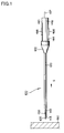
- Fig. 1 is a side view of assistance in explaining a Veress needle according to a first embodiment
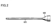
- Fig. 2 is a side view of assistance in explaining a tubular sleeve illustrated in Fig. 1
- Fig. 3 is a side view of assistance in explaining a puncturing needle illustrated in Fig. 1
- Figs. 4 and 5 are a plan view and a cross-sectional view of assistance in explaining a distal end portion illustrated in Fig. 1
- Figs. 6 and 7 are a plan view and a cross-sectional view of assistance in explaining an operating unit at a proximal end portion illustrated in Fig. 1
- Fig. 8 is a perspective view of assistance in explaining a locking device illustrated in Fig. 6 .
- a Veress needle 100 has a puncturing needle 110, a tubular sleeve 120, an insertion member 130, a pullout preventing device 105 and an operating unit 140 at the proximal end portion, and is used to puncture a wall portion 190 of a living body.
- the wall portion 190 is a vaginal wall when the Veress needle is applied to the transvaginal hydrolaparoscopy (THL).
- TTL transvaginal hydrolaparoscopy
- the wall portion 190 is not limited to the vaginal wall, and may also be an abdominal wall.
- the puncturing needle 110 is a hollow tube, and has a distal end portion 114 at which a sharp needle tip 112 is formed and a proximal end portion 116 to which a needle hub 170 is connected (see Fig. 3 ).
- the needle hub 170 has a hollow shape, and is used to connect the proximal end portion 116 of the puncturing needle 110 to the operating unit 140 at the proximal end portion.
- the tubular sleeve 120 (see Fig. 2 ) has a lumen 128 in which the puncturing needle 110 is inserted (see Figs. 5 and 7 ), and a proximal end portion at which a sleeve hub 122 for connecting the operating unit 140 at the proximal end portion is disposed.
- the outer hub 122 is positioned on an outer side of the needle hub 170, and is detachably attached (connected) to the operating unit 140 at the proximal end portion.
- the tubular sleeve 120 is detached from the operating unit 140 at the proximal end portion when puncturing is completed, and is indwelled in a puncturing site.
- the tubular sleeve 120 forms an outer needle of an indwelling needle and the puncturing needle 110 forms an inner needle of the indwelling needle.
- the insertion member 130 has a distal end portion 134 which is slidably (movably in an axial direction S) inserted in the lumen 118 of the puncturing needle 110 and which protrudes from the distal end portion 114 of the puncturing needle 110, and a proximal end portion 136 which extends inside the operating unit 140 at the proximal end portion.
- the distal end portion 134 is formed to guard the needle tip 112 to prevent a damage on an organ positioned on an inner side of a puncturing site of the wall portion 190 (see Figs. 4 and 5 ).
- the proximal end portion 136 has an extended portion 172 which protrudes in a direction which crosses the axial direction S of the insertion member 130, and the extended portion 172 is integrally formed by the proximal end portion 136 (see Fig. 7 ).
- the pullout preventing device 105 is used to prevent the needle tip 112 from being pulled out from the puncturing site in conjunction with protruding movement of the distal end portion 134 of the insertion member 130 from the lumen 118 of the puncturing needle 110 after a load of the puncturing disappears.
- the operating unit 140 at the proximal end portion has a distal end portion 144 which is positioned on a proximal end portion side of the puncturing needle 110 and which is integrally formed with the needle hub 170, a cap portion 146 which is positioned at the proximal end portion and an outer periphery portion at which an opening 149 is disposed, and includes an urging device 150 and a locking device 160 disposed therein (see Figs. 6 and 7 ).
- the proximal end portion 136 of the insertion member 130 penetrates the cap portion 146, and an end surface 137 of the proximal end portion 136 which protrudes outward is adapted to be accommodated inside the operating unit 140 at the proximal end portion when puncturing is completed, so that it is possible to check that puncturing is completed, based on a change in the position of the end surface 137.
- a length of the proximal end portion 136 of the insertion member 130 is set to enable completion of puncturing to be visually checked, and the end surface 137 which protrudes outward from the cap portion 146 forms a checking device for visually checking completion of the puncturing. Consequently, it is possible to improve operability, and make a structure of the checking device simple.
- the urging device 150 is formed by an elastic body (spring) which urges the extended portion 172 of the proximal endportion 136 of the insertion member 130 towards the distal end portion side, and is disposed between the extended portion 172 and the cap portion 146.
- the urging device 150 is adapted to urge the insertion member 130 such that, before puncturing is performed by means of the needle tip 112 (in a state in which the load of puncturing does not apply) and after the load of the puncturing disappears, the distal end portion 134 of the insertion member 130 protrudes from the needle tip 112, and the distal end portion 134 of the insertion member 130 is retreated to the lumen 118 of the puncturing needle 110 by the load of puncturing upon puncturing by means of the needle tip 112.
- the locking device 160 is adapted to lock movement of the insertion member 130 in the urging direction in the lumen 118 of the puncturing needle 110 to define an initial position of the distal end portion 134 of the insertion member 130 before puncturing is performed by means of the needle tip 112, and unlock the lock when the distal end portion 134 of the insertion member 130 is retreated to the lumen 118 of the puncturing needle 110.
- the urging direction matches with the axial direction S leading to the distal end portion.
- the distal end portion 134 of the insertion member 130 is set at an initial position to slightly protrude from the leading end of a bevel (blade surface) of the needle tip 112 of the puncturing needle 110, and guard the needle tip 112 (see Figs. 4 and 5 ).
- the locking device 160 has a sliding portion 162, hooks 164 and arms 166 as illustrated in Fig. 8 .
- the sliding portion 162 has a cylindrical shape, is disposed closer to the proximal end portion side than the extended portion 172 of the proximal end portion 136 of the insertion member 130, is driven by abutting a proximal end portion side surface of the extended portion 172 on the sliding portion 162 and moves along the proximal end portion 136 of the insertion member 130.
- the proximal end portion side surface of the extended portion 172 moves based on retreating movement of the distal end portion 134 of the insertion member 130 to the lumen 118 of the puncturing needle 110.
- the hooks 164 lock movement of the insertion member 130 in the urging direction S when engaging with the insertion member 130, and unlock the lock when separated from the insertion member 130 based on the retreating movement of the distal end portion 134 of the insertion member 130 to the lumen 118 of the puncturing needle 110.
- the hooks 164 have claw shapes, are disposed closer to the distal end portion side than the extended portion 172, abut on and engage with the distal end portion side surface of the extended portion 172 and lock movement of the insertion member 130 in the urging direction (in the axial direction S leading to the distal end portion).
- the arms 166 are extended from the outer periphery of the distal end (needle hub 170) of the operating unit 140 at the proximal end portion, and connects the sliding portion 162 and the hooks 164 through the opening 149 of the operating unit 140 at the proximal end portion.
- the hooks 164 are adapted to, by moving accompanying the movement of the sliding portion 162 upon movement of the sliding portion 162, be pulled out from the opening 149 (separated from the insertion member 130), disengage the engagement, be elastically deformed and abut (get on) the outer periphery of the operating unit 140 at the proximal end portion.
- protrusion of the insertion member 130 is arrested (stopped) by abutting the extended portion 172 on an inner surface of the distal end portion 144 of the operating unit 140 at the proximal end portion.
- the amount of protrusion of the insertion member 130 is defined by a distance between the distal end side surface of the extended portion 172 and the inner surface of the distal end portion 144 of the operating unit 140 at the proximal end portion at the initial position.
- the pullout preventing device 105 is formed by the distal end portion 134 of the insertion member 130, and the distal end portion 134 is adapted to be in a bent shape (J-shaped structure under natural circumstances), be inserted in the lumen 118 of the puncturing needle 110 in an elastically deformed state, protrudes from the lumen 118 of the puncturing needle 110 after the load of the puncturing disappears, then be restored to the bent shape before elastic deformation and is caught on an inner surface of the puncturing site.
- a bent shape J-shaped structure under natural circumstances
- the pullout preventing device 105 can be formed by a simple structure.
- the distal end portion 134 of the insertion member 130 is formed to bend toward a bevel leading end side 113 of the needle tip 112. This can be accomplished by making a setting to impart a directional character to a cross-sectional shape of the distal end portion 134 of the insertion member 130 and a cross-sectional shape of the lumen 118 of the distal end portion 114 of the puncturing needle 110 and prevent the distal end portion 134 of the insertion member 130 from moving from an orientation position at which bending toward the bevel leading end side 113 is made (the distal end portion 134 of the insertion member 130 from rotating).
- the directional character can be obtained by forming depressions and protrusions in an outer periphery of the insertion member 130 along an extension direction of the insertion member 130 and forming in an inner surface of the lumen 118 of the puncturing needle 110 depressions and protrusions which fit to the above depressions and the protrusions. Further, it is also possible to obtain the directional character by making the cross-sectional shapes in shapes having directional character (for example, rectangular shapes or triangular shapes).
- the Veress needle 100 has the pullout preventing device which prevents a needle tip (puncturing needle) from being pulled out from a puncturing site after the load of the puncturing disappears and puncturing is completed as described above, it is not necessary to prevent the needle tip from being pulled out by way of, for example, deep puncturing. Further, the needle tip is prevented from being pulled out in conjunction with protruding movement of the distal end portion of the insertion member from the lumen of the puncturing needle, so that operability is good.
- a mechanism which interlocks the protruding movement of the distal end portion of the insertion member from the lumen of the puncturing needle and the prevention motion of the needle tip from being pulled out from the puncturing site can be accomplished by a simple structure.
- a mechanism which can lock movement of the insertion member and a mechanism which unlocks the lock based on the retreating movement of the distal end portion of the insertion member to the lumen can be accomplished by simple structures.
- the metal includes stainless steel, Ni-Ti alloy, Cu-Zn alloy, cobalt alloy and tantalum
- the polymer materials include polyamide, polyimide, ultrahigh molecular weight polyethylene, polypropylene and fluorine resin.
- thermoplastic resins such as polycarbonate, polyamide, polysulfone, polyarylate, and methacrylate-butylene-styrene copolymer is cited.
- Figs. 9 and 10 are cross-sectional views of assistance in explaining the distal end portion and the operating unit at the proximal end portion upon start of puncturing
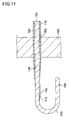
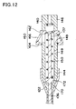
- Figs. 11 and 12 are cross-sectional views of assistance in explaining the distal end portion and the operating unit at the proximal end portion upon completion of puncturing
- Fig. 13 is a cross-sectional view of assistance in explaining how the tubular sleeve is indwelled.
- a distal end portion of the Veress needle 100 is inserted in the vagina.
- the distal end portion 134 of the insertion member 130 protrudes from the distal end portion 114 of the puncturing needle 110 based on an urging force of the urging device 150, and guards the needle tip 112 (see Fig. 5 ).
- the hook 164 of the locking device 160 disposed at the operating unit 140 at the proximal end portion abuts on the distal end portion side surface of the extended portion 172 of the proximal end portion 136 of the insertionmember 130 and, thus, locks movement of the insertion member 130 in the urging direction (in the axial direction S leading to the distal end portion) (see Fig. 7 ).
- the distal end portion 134 of the insertion member 130 is retained in an elastically deformed state (straight state) since being at the initial position although slightly protruding from the bevel leading end side 113 of the needle tip 112 of the puncturing needle 110.
- the distal end portion 134 of the insertion member 130 retreats to the lumen 118 of the puncturing needle 110 against the urging force of the urging device 150 based on a resistance resulting from the aforementioned abutting.
- the distal end portion 114 of the puncturing needle 110 is exposed and, as illustrated in Fig. 9 , the needle tip 112 punctures the wall portion 190 of the vaginal wall.
- the proximal end portion side surface of the extended portion 172 of the proximal end portion 136 of the insertion member 130 abuts on the sliding portion 162 of the locking device 160, and moves (drives) the sliding portion 162 along the proximal end portion 136 of the insertion member 130.
- the hooks 164 of the locking device 160 move accompanying the sliding portion 162, are pulled out from the opening 149 (separated from the insertion member 130), are elastically deformed, and abut on (get on) the outer periphery of the operating unit 140 at the proximal end portion.
- the lock of the extended portion 172 of the proximal end portion 136 of the insertion member 130 is unlocked as illustrated in Fig. 10 .
- the distal end portion 134 of the insertion member 130 protrudes beyond the initial position, and, as illustrated in Fig. 11 , is restored to the bent shape before elastic deformation and is caught on the inner surface of the puncturing site 192, so that the needle tip 112 is prevented from being pulled out from the puncturing site 192.
- the end surface 137 of the proximal end portion 136 of the insertion member 130 protrudes outward from the cap portion 146 of the operating unit 140 at the proximal end portion while puncturing is performed halfway (see Fig. 10 )
- the end surface 137 is accommodated inside the operating unit 140 at the proximal end portion when puncturing is completed (see Fig. 12 ). Consequently, it is possible to visually check that puncturing is completed based on a change in the position of the end surface 137.
- the sleeve hub 122 and the operating unit 140 at the proximal end portion are disconnected, and the operating unit 140 at the proximal end portion is retreated in a state in which the position of the tubular sleeve 120 is fixed.
- the distal end portion 134 of the insertion member 130 is elastically deformed by the resistance generated by abutting on the wall portion 190, becomes straight and passes through the puncturing site 192.
- the tubular sleeve 120 is indwelled in the puncturing site 192, and the tubular sleeve 120 forms the outer needle of the indwelling needle.
- the puncturing needle 110 forms the inner needle of the indwelling needle.
- the tubular sleeve 120 which is indwelled in the puncturing site 192 (functions as the indwelling needle) is used for injection of physiological salt solution, insertion of an endoscope and medical treatment, etc.
- the physiological salt solution is injected between the uterus and the rectum through a cannula inserted in the lumen 128 of the tubular sleeve 120 to float the uterine tube and the ovary.
- the endoscope is inserted to inspect (observe) a surface of the floated uterine tube and ovary after the injection of the physiological salt solution is completed and the cannula is taken out. Inspection items include tubal patency, adhesion around the uterine tube and whether or not an endometriosis develops.
- a medical treatment target is, for example, an endometriosis externa (heterotopic endometriosis), and a needle is inserted to puncture and suction a chocolate cyst.
- a treatment tool inserted in the lumen 128 of the tubular sleeve 120 is not limited to a cannula, an endoscope and a needle for puncturing and suctioning.
- Fig. 14 is a cross-sectional view of assistance in explaining Modified Example according to the first embodiment.
- proximal end portion 136 of the insertion member 130 it is also possible to extend the proximal end portion 136 of the insertion member 130 over the length from the extended portion 172 to the end surface 137, and keep the end surface 137 protruding from the cap portion 146 of the operating unit 140 at the proximal end portion even when puncturing is completed.
- the first embodiment includes the pullout preventing device which prevents the needle tip (puncturing needle) from being pulled out from the puncturing site after the load of the puncturing disappears and puncturing is completed.
- the needle tip is prevented from being pulled out in conjunction with protruding movement of the distal end portion of the insertionmember from the lumen of the puncturing needle, so that operability is good. Consequently, it is possible to provide a Veress needle which can easily prevent the needle tip from being pulled out from the puncturing site.
- Fig. 15 is a cross-sectional view of assistance in explaining a distal end portion of a Veress needle according to the second embodiment
- Fig. 16 is a cross-sectional view of assistance in explaining an operating unit at the proximal end portion of the Veress needle according to the second embodiment.
- the second embodiment relates to a configuration of the pullout preventing device, and roughly differs from the first embodiment in applying the extension of a wire.
- an insertion member 130A is in a hollow shape, and has a lumen 138 in which a wire (second insertion member) 180 is disposed.
- a distal end portion 134 of the insertion member 130A is closed, and a lateral opening 139 which communicates with the lumen 138 is formed.
- the wire 180 has a distal end portion 184 which is connected to a closed portion of the distal end portion 134, and a proximal end portion 186 which passes in the lumen 138 and extends to an outside of the operating unit 140 at the proximal end portion.
- the distal end portion 184 of the wire 180 is in a bent shape and is inserted in the lumen 138 of the insertion member 130A in an elastically deformed state and is adapted to be restored to the bent shape before elastic deformation and is caught on the inner surface of a puncturing site by expanding (protruding) from the lateral opening 139 of the insertion member 130A which protrudes from a lumen 118 of a puncturing needle 110 after a load of the puncturing disappears.
- the pullout preventing device is formed by the distal end portion of the wire, and the pullout preventing device can adopt a simple structure as with the first embodiment.
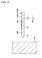
- Fig. 17 is a cross-sectional view of assistance in explaining a distal end portion of a Veress needle according to the third embodiment
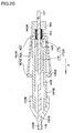
- Fig. 18 is a cross-sectional view of assistance in explaining an operating unit at the proximal end portion of the Veress needle according to the third embodiment.
- the third embodiment roughly differs from the first embodiment in that a tubular sleeve is not provided, an insertion member is formed by a guide wire and the guide wire can be securely indwelled at a puncturing site.
- the Veress needle according to the third embodiment has a puncturing needle 110B, an insertion member 130B, a pullout preventing device 105B and an operating unit 140 at the proximal end portion.
- the puncturing needle 110B has a proximal end portion 116 to which a needle hub 170B is connected.
- the needle hub 170B is separably attached to the operating unit 140B at the proximal end portion.
- the insertion member 130B has a proximal end portion 136B which is extended inside the operating unit 140 at the proximal end portion.
- a fixing connector 172B which forms an extended portion which protrudes in a direction which crosses an axial direction S of the insertion member 130B is detachably fixed.
- the fixing connector 172B is an extended portion of the proximal end portion of the insertion member which is formed by detachable separate member, and has a connector main body 174 and a connector cap 176.
- the connector main body 174 and the connector cap 176 are slidably disposed inside the operating unit 140 at the proximal endportion, and the proximal end portion 136B of the insertion member 130B is inserted (penetrated) thereinto.
- the connector main body 174 is adapted to be able to give a fastening force to the insertion member 130B when the connector main body 174 is slidably attached to the proximal end portion 136B and the connector cap 176 rotates and engages with to the connector main body 174, for example.
- the insertion member 130B it is, for example, possible to allow the insertion member 130B to slide by means of decreasing the fastening force (or by eliminating the fastening force) when the insertion member 130B is inserted in the fixing connector 172B or the insertion member 130B is detached from the fixing connector 172B, and to stop the insertion member 130B from sliding (to fix the fixing connector 172B to the insertion member 130B) by means of increasing the fastening force and increasing a resistance upon movement of the insertion member 130B upon use.
- the insertion member 130B which is formed by the guide wire adopts a multilayer structure, and has a single wire (base material) in a straight shape and a resin layer which covers a surface of the wire.
- the wire is made of nickel titanium, and the resin layer has a lower layer which is closely attached to the wire and a fluorine resin layer which forms an outer shell.
- the insertion member 130B is not limited to the above configuration in particular and can also be formed by a coil member made of nickel titanium or stainless steel, and a urethane resin layer is also applicable as the outer shell of the resin layer.
- the operating unit 144B at the proximal end portion has a distal end portion to which the needle hub 170B is detachable, and has an urging device 150B and a locking device 160B disposed therein.
- the urging device 150B is formed by an elastic member (spring) which urges the fixing connector 172B toward a distal end side, and is disposed between the connector cap 176 and the cap portion 146 of the operating unit 140B at the proximal end portion.
- the hook 164B of the locking device 160B is disposed closer to the distal end portion side than the connector main body 174, and abuts on a distal end portion side surface of the connector main body 174 and locks movement of the insertion member 130 to which the fixing connector 172B is fixed in an urging direction (in the axial direction S leading to the distal end portion) for use of defining an initial position.
- the fixing connector 172B is adapted to stop when the connector main body 174 abuts on an inner surface of the needle hub 170B.
- the amount of protrusion of the insertion member 130B is defined by a distance between the distal end side surface of the connector main body 174 and the inner surface of the needle hub 170B at the initial position.
- Figs. 19 and 20 are cross-sectional views of assistance in explaining the distal end portion and the operating unit at the proximal end portion upon start of puncturing
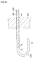
- Figs. 21 and 22 are cross-sectional views of assistance in explaining the distal end portion and the operating unit at the proximal end portion upon completion of puncturing
- Fig. 23 is a cross-sectional view of assistance in explaining separation of the operating unit at the proximal end portion
- Fig. 24 is a cross-sectional view of assistance in explaining separation of the fixing connector
- Fig. 25 is a cross-sectional view of assistance in explaining how the guide wire is indwelled.
- the distal end portion 134 of the insertion member 130B retreats to the lumen 118 of the puncturing needle 110B against an urging force of the urging device 150 based on a resistance resulting from the aforementioned abutting.
- the distal end portion 114 of the puncturing needle 110B is exposed and the wall portion 190 of the vaginal wall is punctured by a needle tip 112 of the distal end portion 114 as illustrated in Fig. 19 .
- the proximal end portion side surface of the connector cap 176 of the fixing connector 172B abuts on a sliding portion 162 of the locking device 160B, and moves (drives) the sliding portion 162 along the proximal end portion 136B of the insertion member 130B.
- hooks 164B of the locking device 160B move accompanying the sliding portion 162, are pulled out from an opening 149 (separated from the insertion member 130B), are elastically deformed, and abut on (get on) the outer periphery of the operating unit 140B at the proximal end portion.
- the lock of the fixing connector 172B (connector main body 174) is unlocked as illustrated in Fig. 20 .
- the needle tip 112 penetrates the wall portion 190 and the resistance resulting from the abutting on the wall portion 190 disappears.
- the distal end portion 134 of the insertion member 130B protrudes from the distal end portion 114 of the puncturing needle 110B based on the urging force of the urging device 150 and guards the needle tip 112. Consequently, it is possible to prevent a damage on an organ positioned on an inner side of a puncturing site 192 of the wall portion 190.
- the lock of the fixing connector 172B is unlocked (the hook 164B does not abut on the distal end portion side surface of the connector main body 174). Therefore, the force of the urging device 150 contracted on the proximal end side is released and the fixing connector 172B moves and abuts on the inner surface of the needle hub 170B as illustrate in Fig. 22 .
- the distal end portion 134 of the insertion member 130B protrudes beyond the initial position, and is restored to a bent shape before elastic deformation and is caught on the inner surface of the puncturing site 192, so that the needle tip 112 is prevented from being pulled out from the puncturing site 192 as illustrated in Fig. 21 .
- the needle hub 170B and the operating unit 140B at the proximal end portion are disconnected, and the operating unit 140B at the proximal end portion is retreated in a state in which the position of the needle hub 170B is fixed. Thereby, the operating unit 140B at the proximal endportion is separated as illustrated in Fig. 23 .
- the fastening force with respect to the insertionmember 130B is weakened (or eliminated) with respect to the insertion member 130B by rotating the connector cap 176, and the fixing connector 172B is slid (moved) along the proximal end portion 136B of the insertion member 130B and is detached from an end surface 137 of the proximal end portion 136B. Thereby, the fixing connector 172B is separated as illustrated in Fig. 24 .
- the needle hub 170B is retreated in a state in which the position of the insertion member 130B is fixed. Thereby, only the insertion member 130B is indwelled in the puncturing site 192 of the wall portion 190 as illustrated in Fig. 25 .
- the insertionmember 130B which is formed by the indwelled guide wire is used for, for example, injection of physiological salt solution, insertion of an endoscope and insertion of a catheter which has a lumen used for medical treatment, etc. After use, bleeding from the puncturing site 192 is stopped as after-treatment.
- the insertion member is formed by the guide wire, so that the guide wire can be securely indwelled in a puncturing site.
- the tubular sleeve according to the first embodiment and the second embodiment can be suitably incorporated in the third embodiment.
- the present invention is not limited to the above embodiments, and can be variously modified within the scope of the claims.
- the present invention is also applicable as a pneumoperitoneum needle for introducing carbon dioxide into an abdominal cavity.
- the pullout preventing device is not limited to the embodiment in which the pullout preventing device is formed by the distal end portion of the insertion member and the embodiment in which the pullout preventing device is disposed at the distal end portion.
- a checking device for visually checking completion of the puncturing as an opening which is disposed on the outer periphery of the operating unit at the proximal end portion, and visually check movement of an extended portion (connector) through the opening.
- a puncturing needle in a hollow shape to allow a catheter, an endoscope, and the like to be inserted therein.
Landscapes
- Health & Medical Sciences (AREA)
- Surgery (AREA)
- Life Sciences & Earth Sciences (AREA)
- Medical Informatics (AREA)
- Nuclear Medicine, Radiotherapy & Molecular Imaging (AREA)
- Engineering & Computer Science (AREA)
- Biomedical Technology (AREA)
- Heart & Thoracic Surgery (AREA)
- Pathology (AREA)
- Molecular Biology (AREA)
- Animal Behavior & Ethology (AREA)
- General Health & Medical Sciences (AREA)
- Public Health (AREA)
- Veterinary Medicine (AREA)
- Surgical Instruments (AREA)
- Infusion, Injection, And Reservoir Apparatuses (AREA)
Abstract
Description
- The present invention relates to a Veress needle.
- When, for example, it is necessary to puncture an abdominal wall or a vaginal wall, a Veress needle with a guarded needle tip is applied to prevent damages on organs positioned on an inner side of a puncturing site (see, for example,
Patent Reference 1 and Patent Reference 2). -
- [Patent reference 1]
JP 5-130999 A - [Patent reference 2]
JP 9-135841 A - However, there is aproblemthat it is difficult to prevent a needle tip from being pulled out from a puncturing site. When, for example, the needle tip is prevented from being pulled out by way of deep puncturing, there is a possibility that organs are damaged even if the needle tip is guarded, and an operator pays significant attention to puncturing to prevent such a situation and therefore operability is very poor.
- The present invention is made in order to solve the abovementioned problem associated with the related art, and to provide a Veress needle which can easily prevent a needle tip from being pulled out from a puncturing site.
- This invention for accomplishing the above-mentioned purpose is a Veress needle comprising a hollow puncturing needle which comprises a distal end portion with a needle tip and a lumen, an insertion member which is slidably inserted in the lumen, an urging device, and a pullout preventing device. The urging device is adapted to urge the insertion member such that, before puncturing is performed by means of the needle tip and after the puncturing is completed, a distal end portion of the insertion member protrudes from the needle tip and, the distal end portion of the insertion member is retreated to the lumen based on a load of the puncturing upon the puncturing by means of the needle tip. The pullout preventing device, after the load of the puncturing disappears, prevents the needle tip from being pulled out from a puncturing site in conjunction with protruding movement of the distal end portion of the insertion member from the lumen.
- Since a pullout preventing device which prevents a needle tip (puncturing needle) from being pulled out from a puncturing site after the load of the puncturing disappears and puncturing is completed is provided, it is not necessary to prevent the needle tip from being pulled out by way of deep puncturing, for example. Further, the needle tip is prevented from being pulled out in conjunction with protruding movement of the distal end portion of the insertion member from the lumen of the puncturing needle, so that operability is good. Consequently, it is possible to provide a Veress needle which can easily prevent the needle tip from being pulled out from the puncturing site.
- Further, when a locking device which is adapted to lock the movement of the insertion member in an urging direction to define an initial position of the distal end portion of the insertion member before the puncturing by means of the needle tip, and, when the distal end portion of the insertion member retreats to the lumen, unlocks the lock and releases an urging force of the urging device is provided in an operating unit which is positioned on a proximal end portion of the puncturing needle and at which the urging device is disposed, the pullout preventing device can prevent the needle tip from being pulled out from the puncturing site based on the protruding movement of the distal end portion of the insertion member beyond the initial position due to the released urging force after the load of the puncturing disappears. In other words, a mechanism which interlocks the protruding movement of the distal end portion of the insertion member from the lumen of the puncturing needle and the prevention motion of the needle tip from being pulled out from the puncturing site can be accomplished by the locking device which adopts a simple structure.
- The locking device may also comprises a hook which locks the movement of the insertion member in the urging direction by means of engaging with the insertion member, and unlocks the lock by means of moving away from the insertion member based on retreating movement of the distal end portion of the insertion member to the lumen. In this case, a mechanism which can lock movement of the insertion member can be accomplished by a simple structure.
- In addition to the hook, the locking device can further comprise: a sliding portion which is disposed closer to the proximal end portion side than an extended portion which is disposed closer to a proximal end portion side than the hook in a proximal end portion of the insertion member and which protrudes in a direction which crosses an axial direction of the insertion member, and which is driven by abutting a proximal end portion side surface of the extended portion which moves based on the retreating movement of the distal end portion of the insertion member to the lumen, and moves along the proximal end portion of the insertion member; and an arm which is extended from an outer periphery of the operating unit at the proximal end portion, and which connects the sliding portion and the hook through an opening formed in the operating unit at the proximal end portion. In this case, the hook engages with the insertion member by means of abutting on a distal end portion side surface of the extended portion, and moves accompanying the movement of the sliding portion, and then is separated from the insertion member and disengages the engagement. Consequently, a mechanism which unlocks the lock based on the retreating movement of the distal end portion of the insertion member to the lumen can be accomplished by a simple structure.
- When the distal end portion of the insertion member which is adapted to be in a bent shape, and be inserted in the lumen in an elastically deformed state, protrude from the lumen after the puncturing is completed, then be restored to the bent shape before elastic deformation and be caught on an inner surface of the puncturing site forms the pullout preventing device, the pullout preventing device can adopt a simple structure.
- When the insertion member is hollow and comprises a lumen in which a second insertion member is inserted, the distal end portion of the insertionmember comprises a lateral opening which communicates with the lumen, and a distal end portion of the second insertion member which is adapted to be in a bent shape, and be inserted in the lumen of the insertion member in an elastically deformed state, be extended from the lateral opening of the insertion member which protrudes from the lumen of the puncturing needle after the load of the puncturing disappears, then be restored to the bent shape before elastic deformation and be caught on the inner surface of the puncturing site forms the pullout preventing device, the pullout preventing device can also adopt a simple structure.
- When the insertion member is detachably attached to the operating unit at the proximal end portion, it is possible to improve the degree of freedom upon use.
- When a hollow tubular sleeve in which the puncturing needle is slidably inserted is detachably attached to the operating unit at the proximal end portion, it is possible to indwell the tubular sleeve in the puncturing site by detaching the tubular sleeve from the operating unit at the proximal end portion (releasing the connection to the operating unit at the proximal end portion) after puncturing is completed. In other words, the tubular sleeve can form an outer needle of an indwelling needle and the puncturing needle can form an inner needle of the indwelling needle.
- At the operating unit at the proximal end portion, it is also possible to dispose a checking device for checking completion of the puncturing visually. In this case, it is possible to improve operability.
- The checking device may be formed by an end surface of the proximal end portion of the insertion member, the end surface adapted to protrude outward from a proximal end portion of the operating unit at the proximal end portion when being at the initial position, and be accommodated in the operating unit at the proximal end portion when the puncturing is completed. In this case, the checking device can adopt a simple structure.
- The insertion member may be formed by a guide wire which is adapted to be separably from the puncturing needle and the operating unit at the proximal end portion. In this case, it is possible to securely indwell the guide wire in the puncturing site.
- The extended portion at the proximal end portion of the insertionmembermaybe formed by a detachable different member. In this case, interference of the extendedportion is prevented by detaching the extended portion from the proximal end portion of the insertion member, so that it is possible to easily separate the insertion member from the puncturing needle and the operating unit at the proximal end portion.
- The objects, features, and characteristics of this invention other than those set forth above will become apparent from the description given herein below with reference to preferred embodiments illustrated in the accompanying drawings.
-
-
Fig. 1 is a side view of assistance in explaining a Veress needle according to a first embodiment. -
Fig. 2 is a side view of assistance in explaining a tubular sleeve illustrated inFig. 1 . -
Fig. 3 is a side view of assistance in explaining a puncturing needle illustrated inFig. 1 . -
Fig. 4 is a plan view of assistance in explaining a distal end portion illustrated inFig. 1 . -
Fig. 5 is a cross-sectional view of assistance in explaining the distal end portion illustrated inFig. 1 . -
Fig. 6 is a plan view of assistance in explaining an operating unit at a proximal end portion illustrated inFig. 1 . -
Fig. 7 is a cross-sectional view of assistance in explaining the operating unit at the proximal end portion illustrated inFig. 1 . -
Fig. 8 is a perspective view of assistance in explaining a locking device illustrated inFig. 6 . -
Fig. 9 is a cross-sectional view of assistance in explaining a method of using the Veress needle according to the first embodiment, and illustrates the distal end portion upon start of puncturing. -
Fig. 10 is a cross-sectional view of assistance in explaining the operating unit at the proximal end portion upon start of puncturing. -
Fig. 11 is a cross-sectional view of assistance in explaining the distal end portion upon completion of puncturing. -
Fig. 12 is a cross-sectional view of assistance in explaining the operating unit at the proximal end portion upon completion of puncturing. -
Fig. 13 is a cross-sectional view of assistance in explaining how the tubular sleeve is indwelled. -
Fig. 14 is a cross-sectional view of assistance in explaining Modified Example according to the first embodiment. -
Fig. 15 is a cross-sectional view of assistance in explaining a distal end portion of a Veress needle according to a second embodiment. -
Fig. 16 is a cross-sectional view of assistance in explaining an operating unit at a proximal end portion of the Veress needle according to the second embodiment. -
Fig. 17 is a cross-sectional view of assistance in explaining a distal end portion of a Veress needle according to a third embodiment. -
Fig. 18 is a cross-sectional view of assistance in explaining an operating unit at a proximal end portion of the Veress needle according to the third embodiment. -
Fig. 19 is a cross-sectional view of assistance in explaining a method of using the Veress needle according to the third embodiment, and illustrates the distal end portion upon start of puncturing. -
Fig. 20 is a cross-sectional view of assistance in explaining the operating unit at the proximal end portion upon start of puncturing. -
Fig. 21 is a cross-sectional view of assistance in explaining the distal end portion upon completion of puncturing. -
Fig. 22 is a cross-sectional view of assistance in explaining the operating unit at the proximal end portion upon completion of puncturing. -
Fig. 23 is a cross-sectional view of assistance in explaining separation of the operating unit at the proximal end portion. -
Fig. 24 is a cross-sectional view of assistance in explaining separation of a fixing connector. -
Fig. 25 is a cross-sectional view of assistance in explaining how a guide wire is indwelled. - Hereinafter, embodiments of the present invention will be described referring to the drawings.
-
Fig. 1 is a side view of assistance in explaining a Veress needle according to a first embodiment,Fig. 2 is a side view of assistance in explaining a tubular sleeve illustrated inFig. 1 ,Fig. 3 is a side view of assistance in explaining a puncturing needle illustrated inFig. 1 ,Figs. 4 and 5 are a plan view and a cross-sectional view of assistance in explaining a distal end portion illustrated inFig. 1 ,Figs. 6 and7 are a plan view and a cross-sectional view of assistance in explaining an operating unit at a proximal end portion illustrated inFig. 1 andFig. 8 is a perspective view of assistance in explaining a locking device illustrated inFig. 6 . - As illustrated in
Fig. 1 , aVeress needle 100 according to the first embodiment has a puncturingneedle 110, atubular sleeve 120, aninsertion member 130, apullout preventing device 105 and anoperating unit 140 at the proximal end portion, and is used to puncture awall portion 190 of a living body. Thewall portion 190 is a vaginal wall when the Veress needle is applied to the transvaginal hydrolaparoscopy (THL). Thewall portion 190 is not limited to the vaginal wall, and may also be an abdominal wall. - The puncturing
needle 110 is a hollow tube, and has adistal end portion 114 at which asharp needle tip 112 is formed and aproximal end portion 116 to which aneedle hub 170 is connected (seeFig. 3 ). Theneedle hub 170 has a hollow shape, and is used to connect theproximal end portion 116 of the puncturingneedle 110 to theoperating unit 140 at the proximal end portion. - The tubular sleeve 120 (see
Fig. 2 ) has alumen 128 in which the puncturingneedle 110 is inserted (seeFigs. 5 and7 ), and a proximal end portion at which asleeve hub 122 for connecting theoperating unit 140 at the proximal end portion is disposed. Theouter hub 122 is positioned on an outer side of theneedle hub 170, and is detachably attached (connected) to theoperating unit 140 at the proximal end portion. Thetubular sleeve 120 is detached from theoperating unit 140 at the proximal end portion when puncturing is completed, and is indwelled in a puncturing site. In other words, thetubular sleeve 120 forms an outer needle of an indwelling needle and the puncturingneedle 110 forms an inner needle of the indwelling needle. - The
insertion member 130 has adistal end portion 134 which is slidably (movably in an axial direction S) inserted in thelumen 118 of the puncturingneedle 110 and which protrudes from thedistal end portion 114 of the puncturingneedle 110, and aproximal end portion 136 which extends inside theoperating unit 140 at the proximal end portion. Thedistal end portion 134 is formed to guard theneedle tip 112 to prevent a damage on an organ positioned on an inner side of a puncturing site of the wall portion 190 (seeFigs. 4 and 5 ). Theproximal end portion 136 has an extendedportion 172 which protrudes in a direction which crosses the axial direction S of theinsertion member 130, and theextended portion 172 is integrally formed by the proximal end portion 136 (seeFig. 7 ). - The
pullout preventing device 105 is used to prevent theneedle tip 112 from being pulled out from the puncturing site in conjunction with protruding movement of thedistal end portion 134 of theinsertion member 130 from thelumen 118 of the puncturingneedle 110 after a load of the puncturing disappears. - The
operating unit 140 at the proximal end portion has adistal end portion 144 which is positioned on a proximal end portion side of the puncturingneedle 110 and which is integrally formed with theneedle hub 170, acap portion 146 which is positioned at the proximal end portion and an outer periphery portion at which anopening 149 is disposed, and includes anurging device 150 and alocking device 160 disposed therein (seeFigs. 6 and7 ). - The
proximal end portion 136 of theinsertion member 130 penetrates thecap portion 146, and anend surface 137 of theproximal end portion 136 which protrudes outward is adapted to be accommodated inside theoperating unit 140 at the proximal end portion when puncturing is completed, so that it is possible to check that puncturing is completed, based on a change in the position of theend surface 137. In other words, a length of theproximal end portion 136 of theinsertion member 130 is set to enable completion of puncturing to be visually checked, and theend surface 137 which protrudes outward from thecap portion 146 forms a checking device for visually checking completion of the puncturing. Consequently, it is possible to improve operability, and make a structure of the checking device simple. - The urging
device 150 is formed by an elastic body (spring) which urges theextended portion 172 of theproximal endportion 136 of theinsertion member 130 towards the distal end portion side, and is disposed between theextended portion 172 and thecap portion 146. The urgingdevice 150 is adapted to urge theinsertion member 130 such that, before puncturing is performed by means of the needle tip 112 (in a state in which the load of puncturing does not apply) and after the load of the puncturing disappears, thedistal end portion 134 of theinsertion member 130 protrudes from theneedle tip 112, and thedistal end portion 134 of theinsertion member 130 is retreated to thelumen 118 of the puncturingneedle 110 by the load of puncturing upon puncturing by means of theneedle tip 112. - The
locking device 160 is adapted to lock movement of theinsertion member 130 in the urging direction in thelumen 118 of the puncturingneedle 110 to define an initial position of thedistal end portion 134 of theinsertion member 130 before puncturing is performed by means of theneedle tip 112, and unlock the lock when thedistal end portion 134 of theinsertion member 130 is retreated to thelumen 118 of the puncturingneedle 110. The urging direction matches with the axial direction S leading to the distal end portion. In addition, thedistal end portion 134 of theinsertion member 130 is set at an initial position to slightly protrude from the leading end of a bevel (blade surface) of theneedle tip 112 of the puncturingneedle 110, and guard the needle tip 112 (seeFigs. 4 and 5 ). - Specifically speaking, the
locking device 160 has a slidingportion 162, hooks 164 andarms 166 as illustrated inFig. 8 . - The sliding
portion 162 has a cylindrical shape, is disposed closer to the proximal end portion side than theextended portion 172 of theproximal end portion 136 of theinsertion member 130, is driven by abutting a proximal end portion side surface of theextended portion 172 on the slidingportion 162 and moves along theproximal end portion 136 of theinsertion member 130. The proximal end portion side surface of theextended portion 172 moves based on retreating movement of thedistal end portion 134 of theinsertion member 130 to thelumen 118 of the puncturingneedle 110. - The
hooks 164 lock movement of theinsertion member 130 in the urging direction S when engaging with theinsertion member 130, and unlock the lock when separated from theinsertion member 130 based on the retreating movement of thedistal end portion 134 of theinsertion member 130 to thelumen 118 of the puncturingneedle 110. In the present embodiment, thehooks 164 have claw shapes, are disposed closer to the distal end portion side than theextended portion 172, abut on and engage with the distal end portion side surface of theextended portion 172 and lock movement of theinsertion member 130 in the urging direction (in the axial direction S leading to the distal end portion). - The
arms 166 are extended from the outer periphery of the distal end (needle hub 170) of theoperating unit 140 at the proximal end portion, and connects the slidingportion 162 and thehooks 164 through theopening 149 of theoperating unit 140 at the proximal end portion. - The
hooks 164 are adapted to, by moving accompanying the movement of the slidingportion 162 upon movement of the slidingportion 162, be pulled out from the opening 149 (separated from the insertion member 130), disengage the engagement, be elastically deformed and abut (get on) the outer periphery of theoperating unit 140 at the proximal end portion. - Since the
hooks 164 do not abut on the distal end portion side surface of theextended portion 172 of theproximal end portion 136 of theinsertion member 130 when thedistal end portion 134 of theinsertion member 130 protrudes from thelumen 118 of the puncturingneedle 110 after the load of the puncturing disappears, a force of the urgingdevice 150 contracted on the proximal end side is released and thedistal end portion 134 of theinsertion member 130 protrudes beyond the initial position. - In addition, protrusion of the
insertion member 130 is arrested (stopped) by abutting theextended portion 172 on an inner surface of thedistal end portion 144 of theoperating unit 140 at the proximal end portion. Hence, the amount of protrusion of theinsertion member 130 is defined by a distance between the distal end side surface of theextended portion 172 and the inner surface of thedistal end portion 144 of theoperating unit 140 at the proximal end portion at the initial position. - The
pullout preventing device 105 according to the present embodiment is formed by thedistal end portion 134 of theinsertion member 130, and thedistal end portion 134 is adapted to be in a bent shape (J-shaped structure under natural circumstances), be inserted in thelumen 118 of the puncturingneedle 110 in an elastically deformed state, protrudes from thelumen 118 of the puncturingneedle 110 after the load of the puncturing disappears, then be restored to the bent shape before elastic deformation and is caught on an inner surface of the puncturing site. In other words, after the load of the puncturing disappears and puncturing is completed, theneedle tip 112 is prevented from being pulled out from the puncturing site based on protruding movement of the unlockeddistal end portion 134 of theinsertion member 130 beyond the initial position. Consequently, thepullout preventing device 105 can be formed by a simple structure. - In addition, in order to securely guard the
needle tip 112, it is preferable that thedistal end portion 134 of theinsertion member 130 is formed to bend toward a bevel leadingend side 113 of theneedle tip 112. This can be accomplished by making a setting to impart a directional character to a cross-sectional shape of thedistal end portion 134 of theinsertion member 130 and a cross-sectional shape of thelumen 118 of thedistal end portion 114 of the puncturingneedle 110 and prevent thedistal end portion 134 of theinsertion member 130 from moving from an orientation position at which bending toward the bevel leadingend side 113 is made (thedistal end portion 134 of theinsertion member 130 from rotating). For example, the directional character can be obtained by forming depressions and protrusions in an outer periphery of theinsertion member 130 along an extension direction of theinsertion member 130 and forming in an inner surface of thelumen 118 of the puncturingneedle 110 depressions and protrusions which fit to the above depressions and the protrusions. Further, it is also possible to obtain the directional character by making the cross-sectional shapes in shapes having directional character (for example, rectangular shapes or triangular shapes). - Since the
Veress needle 100 has the pullout preventing device which prevents a needle tip (puncturing needle) from being pulled out from a puncturing site after the load of the puncturing disappears and puncturing is completed as described above, it is not necessary to prevent the needle tip from being pulled out by way of, for example, deep puncturing. Further, the needle tip is prevented from being pulled out in conjunction with protruding movement of the distal end portion of the insertion member from the lumen of the puncturing needle, so that operability is good. - Furthermore, a mechanism which interlocks the protruding movement of the distal end portion of the insertion member from the lumen of the puncturing needle and the prevention motion of the needle tip from being pulled out from the puncturing site can be accomplished by a simple structure.
- Still further, a mechanism which can lock movement of the insertion member and a mechanism which unlocks the lock based on the retreating movement of the distal end portion of the insertion member to the lumen can be accomplished by simple structures.
- As materials for forming the puncturing
needle 110, thetubular sleeve 120 and theinsertion member 130, flexible metals, polymer materials with relatively high rigidity or suitable combinations of these are cited. For example, the metal includes stainless steel, Ni-Ti alloy, Cu-Zn alloy, cobalt alloy and tantalum, and the polymer materials include polyamide, polyimide, ultrahigh molecular weight polyethylene, polypropylene and fluorine resin. - As materials for forming the
sleeve hub 122 and theneedle hub 170, thermoplastic resins such as polycarbonate, polyamide, polysulfone, polyarylate, and methacrylate-butylene-styrene copolymer is cited. - Next, a method of using the Veress needle according to the first embodiment will be described.
-
Figs. 9 and10 are cross-sectional views of assistance in explaining the distal end portion and the operating unit at the proximal end portion upon start of puncturing,Figs. 11 and12 are cross-sectional views of assistance in explaining the distal end portion and the operating unit at the proximal end portion upon completion of puncturing, andFig. 13 is a cross-sectional view of assistance in explaining how the tubular sleeve is indwelled. - When the Veress needle is applied to the transvaginal hydrolaparoscopy, disinfection of an external genitalia and the inside of a vagina, insertion of an ultrasonic probe and expansion of a vaginal fornix by means of Cusco speculum, etc. are performed as preliminary arrangements.
- Then, a distal end portion of the
Veress needle 100 is inserted in the vagina. At this point, thedistal end portion 134 of theinsertion member 130 protrudes from thedistal end portion 114 of the puncturingneedle 110 based on an urging force of the urgingdevice 150, and guards the needle tip 112 (seeFig. 5 ). Meanwhile, thehook 164 of thelocking device 160 disposed at theoperating unit 140 at the proximal end portion abuts on the distal end portion side surface of theextended portion 172 of theproximal end portion 136 of theinsertionmember 130 and, thus, locks movement of theinsertion member 130 in the urging direction (in the axial direction S leading to the distal end portion) (seeFig. 7 ). In other words, thedistal end portion 134 of theinsertion member 130 is retained in an elastically deformed state (straight state) since being at the initial position although slightly protruding from the bevel leadingend side 113 of theneedle tip 112 of the puncturingneedle 110. - Further, when abutting on the
wall portion 190, thedistal end portion 134 of theinsertion member 130 retreats to thelumen 118 of the puncturingneedle 110 against the urging force of the urgingdevice 150 based on a resistance resulting from the aforementioned abutting. Thereby, thedistal end portion 114 of the puncturingneedle 110 is exposed and, as illustrated inFig. 9 , theneedle tip 112 punctures thewall portion 190 of the vaginal wall. - At this point, the proximal end portion side surface of the
extended portion 172 of theproximal end portion 136 of theinsertion member 130 abuts on the slidingportion 162 of thelocking device 160, and moves (drives) the slidingportion 162 along theproximal end portion 136 of theinsertion member 130. Thereby, thehooks 164 of thelocking device 160 move accompanying the slidingportion 162, are pulled out from the opening 149 (separated from the insertion member 130), are elastically deformed, and abut on (get on) the outer periphery of theoperating unit 140 at the proximal end portion. Thus, the lock of theextended portion 172 of theproximal end portion 136 of theinsertion member 130 is unlocked as illustrated inFig. 10 . - Then, when the
needle tip 112 penetrates thewall portion 190, the resistance resulting from the abutting on thewall portion 190 disappears, and thedistal end portion 134 of theinsertion member 130 protrudes from thedistal end portion 114 of the puncturingneedle 110 based on the urging force of the urgingdevice 150 and guards theneedle tip 112. Consequently, it is possible to prevent the damage on the organ positioned on the inner side of thepuncturing site 192 of thewall portion 190. - At this point, the lock of the
extended portion 172 of theproximal end portion 136 of theinsertion member 130 by means of thehook 164 of thelocking device 160 is unlocked (thehook 164 does not abut on the distal end portion side surface of the extended portion 172). Thus, the force of the urgingdevice 150 contracted on the proximal end side is released and theextended portion 172 moves to abut on the inner surface of thedistal end portion 144 of theoperating unit 140 at the proximal end portion as illustrated inFig. 12 . - Thereby, the
distal end portion 134 of theinsertion member 130 protrudes beyond the initial position, and, as illustrated inFig. 11 , is restored to the bent shape before elastic deformation and is caught on the inner surface of thepuncturing site 192, so that theneedle tip 112 is prevented from being pulled out from thepuncturing site 192. - Further, although the
end surface 137 of theproximal end portion 136 of theinsertion member 130 protrudes outward from thecap portion 146 of theoperating unit 140 at the proximal end portion while puncturing is performed halfway (seeFig. 10 ), theend surface 137 is accommodated inside theoperating unit 140 at the proximal end portion when puncturing is completed (seeFig. 12 ). Consequently, it is possible to visually check that puncturing is completed based on a change in the position of theend surface 137. - Next, the
sleeve hub 122 and theoperating unit 140 at the proximal end portion are disconnected, and theoperating unit 140 at the proximal end portion is retreated in a state in which the position of thetubular sleeve 120 is fixed. Thereby, thedistal end portion 134 of theinsertion member 130 is elastically deformed by the resistance generated by abutting on thewall portion 190, becomes straight and passes through thepuncturing site 192. Meanwhile, as illustrated inFig. 13 , thetubular sleeve 120 is indwelled in thepuncturing site 192, and thetubular sleeve 120 forms the outer needle of the indwelling needle. In addition, the puncturingneedle 110 forms the inner needle of the indwelling needle. - The
tubular sleeve 120 which is indwelled in the puncturing site 192 (functions as the indwelling needle) is used for injection of physiological salt solution, insertion of an endoscope and medical treatment, etc. - For example, the physiological salt solution is injected between the uterus and the rectum through a cannula inserted in the
lumen 128 of thetubular sleeve 120 to float the uterine tube and the ovary. For example, the endoscope is inserted to inspect (observe) a surface of the floated uterine tube and ovary after the injection of the physiological salt solution is completed and the cannula is taken out. Inspection items include tubal patency, adhesion around the uterine tube and whether or not an endometriosis develops. - A medical treatment target is, for example, an endometriosis externa (heterotopic endometriosis), and a needle is inserted to puncture and suction a chocolate cyst.
- Further, after use, bleeding from the
puncturing site 192 is stopped as after-treatment. In addition, a treatment tool inserted in thelumen 128 of thetubular sleeve 120 is not limited to a cannula, an endoscope and a needle for puncturing and suctioning. -
Fig. 14 is a cross-sectional view of assistance in explaining Modified Example according to the first embodiment. - It is also possible to extend the
proximal end portion 136 of theinsertion member 130 over the length from theextended portion 172 to theend surface 137, and keep theend surface 137 protruding from thecap portion 146 of theoperating unit 140 at the proximal end portion even when puncturing is completed. In this case, it is possible to retreat thedistal end portion 134 of theinsertion member 130 to thelumen 118 of the puncturingneedle 110 to make thehook 164 and the distal end portion side surface of theextendedportion 172 abut again and return to initial positions by gripping the vicinity of theend surface 137 and moving theinsertion member 130 against the urging force in a state in which the position of theoperating unit 140 at the proximal end portion is fixed, for example.
As described above, the first embodiment includes the pullout preventing device which prevents the needle tip (puncturing needle) from being pulled out from the puncturing site after the load of the puncturing disappears and puncturing is completed. Thus, it is not necessary to prevent the needle tip from being pulled out by way of deep puncturing, for example. Further, the needle tip is prevented from being pulled out in conjunction with protruding movement of the distal end portion of the insertionmember from the lumen of the puncturing needle, so that operability is good. Consequently, it is possible to provide a Veress needle which can easily prevent the needle tip from being pulled out from the puncturing site. - Next, the second embodiment will be described. In addition, members having the same functions as those in the first embodiment will be assigned similar reference numerals, and descriptions of the members will be suitably omitted to prevent duplication.
-
Fig. 15 is a cross-sectional view of assistance in explaining a distal end portion of a Veress needle according to the second embodiment, andFig. 16 is a cross-sectional view of assistance in explaining an operating unit at the proximal end portion of the Veress needle according to the second embodiment. - The second embodiment relates to a configuration of the pullout preventing device, and roughly differs from the first embodiment in applying the extension of a wire.
- Specifically, an
insertion member 130A is in a hollow shape, and has alumen 138 in which a wire (second insertion member) 180 is disposed. Adistal end portion 134 of theinsertion member 130A is closed, and alateral opening 139 which communicates with thelumen 138 is formed. Thewire 180 has adistal end portion 184 which is connected to a closed portion of thedistal end portion 134, and aproximal end portion 186 which passes in thelumen 138 and extends to an outside of theoperating unit 140 at the proximal end portion. - The
distal end portion 184 of thewire 180 is in a bent shape and is inserted in thelumen 138 of theinsertion member 130A in an elastically deformed state and is adapted to be restored to the bent shape before elastic deformation and is caught on the inner surface of a puncturing site by expanding (protruding) from thelateral opening 139 of theinsertion member 130A which protrudes from alumen 118 of a puncturingneedle 110 after a load of the puncturing disappears. - In the second embodiment as described above, in the second embodiment, the pullout preventing device is formed by the distal end portion of the wire, and the pullout preventing device can adopt a simple structure as with the first embodiment.
- Next, the third embodiment will be described.
-
Fig. 17 is a cross-sectional view of assistance in explaining a distal end portion of a Veress needle according to the third embodiment, andFig. 18 is a cross-sectional view of assistance in explaining an operating unit at the proximal end portion of the Veress needle according to the third embodiment. - The third embodiment roughly differs from the first embodiment in that a tubular sleeve is not provided, an insertion member is formed by a guide wire and the guide wire can be securely indwelled at a puncturing site.
- Specifically, the Veress needle according to the third embodiment has a puncturing
needle 110B, aninsertion member 130B, apullout preventing device 105B and anoperating unit 140 at the proximal end portion. - The puncturing
needle 110B has aproximal end portion 116 to which aneedle hub 170B is connected. Theneedle hub 170B is separably attached to theoperating unit 140B at the proximal end portion. - The
insertion member 130B has aproximal end portion 136B which is extended inside theoperating unit 140 at the proximal end portion. To theproximal end portion 136B, a fixingconnector 172B which forms an extended portion which protrudes in a direction which crosses an axial direction S of theinsertion member 130B is detachably fixed. - The fixing
connector 172B is an extended portion of the proximal end portion of the insertion member which is formed by detachable separate member, and has a connectormain body 174 and aconnector cap 176. The connectormain body 174 and theconnector cap 176 are slidably disposed inside theoperating unit 140 at the proximal endportion, and theproximal end portion 136B of theinsertion member 130B is inserted (penetrated) thereinto. Inaddition, the connectormain body 174 is adapted to be able to give a fastening force to theinsertion member 130B when the connectormain body 174 is slidably attached to theproximal end portion 136B and theconnector cap 176 rotates and engages with to the connectormain body 174, for example. - Thereby, it is, for example, possible to allow the
insertion member 130B to slide by means of decreasing the fastening force (or by eliminating the fastening force) when theinsertion member 130B is inserted in the fixingconnector 172B or theinsertion member 130B is detached from the fixingconnector 172B, and to stop theinsertion member 130B from sliding (to fix the fixingconnector 172B to theinsertion member 130B) by means of increasing the fastening force and increasing a resistance upon movement of theinsertion member 130B upon use. - In addition, the
insertion member 130B which is formed by the guide wire adopts a multilayer structure, and has a single wire (base material) in a straight shape and a resin layer which covers a surface of the wire. The wire is made of nickel titanium, and the resin layer has a lower layer which is closely attached to the wire and a fluorine resin layer which forms an outer shell. Theinsertion member 130B is not limited to the above configuration in particular and can also be formed by a coil member made of nickel titanium or stainless steel, and a urethane resin layer is also applicable as the outer shell of the resin layer. - The
operating unit 144B at the proximal end portion has a distal end portion to which theneedle hub 170B is detachable, and has an urging device 150B and alocking device 160B disposed therein. - The urging device 150B is formed by an elastic member (spring) which urges the fixing
connector 172B toward a distal end side, and is disposed between theconnector cap 176 and thecap portion 146 of theoperating unit 140B at the proximal end portion. Thehook 164B of thelocking device 160B is disposed closer to the distal end portion side than the connectormain body 174, and abuts on a distal end portion side surface of the connectormain body 174 and locks movement of theinsertion member 130 to which the fixingconnector 172B is fixed in an urging direction (in the axial direction S leading to the distal end portion) for use of defining an initial position. In addition, the fixingconnector 172B is adapted to stop when the connectormain body 174 abuts on an inner surface of theneedle hub 170B. Hence, the amount of protrusion of theinsertion member 130B is defined by a distance between the distal end side surface of the connectormain body 174 and the inner surface of theneedle hub 170B at the initial position. - Next, a method of using the Veress needle according to the third embodiment will be described.
-
Figs. 19 and20 are cross-sectional views of assistance in explaining the distal end portion and the operating unit at the proximal end portion upon start of puncturing,Figs. 21 and22 are cross-sectional views of assistance in explaining the distal end portion and the operating unit at the proximal end portion upon completion of puncturing,Fig. 23 is a cross-sectional view of assistance in explaining separation of the operating unit at the proximal end portion,Fig. 24 is a cross-sectional view of assistance in explaining separation of the fixing connector andFig. 25 is a cross-sectional view of assistance in explaining how the guide wire is indwelled. - When the Veress needle is applied to the transvaginal hydrolaparoscopy, preliminary arrangements and insertion of the distal end portion of the Veress needle into the vagina are conducted as with the first embodiment.
- Further, when abutting on a
wall portion 190, thedistal end portion 134 of theinsertion member 130B retreats to thelumen 118 of the puncturingneedle 110B against an urging force of the urgingdevice 150 based on a resistance resulting from the aforementioned abutting. Thereby, thedistal end portion 114 of the puncturingneedle 110B is exposed and thewall portion 190 of the vaginal wall is punctured by aneedle tip 112 of thedistal end portion 114 as illustrated inFig. 19 . - At this point, the proximal end portion side surface of the
connector cap 176 of the fixingconnector 172B abuts on a slidingportion 162 of thelocking device 160B, and moves (drives) the slidingportion 162 along theproximal end portion 136B of theinsertion member 130B. Thereby, hooks 164B of thelocking device 160B move accompanying the slidingportion 162, are pulled out from an opening 149 (separated from theinsertion member 130B), are elastically deformed, and abut on (get on) the outer periphery of theoperating unit 140B at the proximal end portion. Thus, the lock of the fixingconnector 172B (connector main body 174) is unlocked as illustrated inFig. 20 . - Then, the
needle tip 112 penetrates thewall portion 190 and the resistance resulting from the abutting on thewall portion 190 disappears. Thus, thedistal end portion 134 of theinsertion member 130B protrudes from thedistal end portion 114 of the puncturingneedle 110B based on the urging force of the urgingdevice 150 and guards theneedle tip 112. Consequently, it is possible to prevent a damage on an organ positioned on an inner side of apuncturing site 192 of thewall portion 190. - At this point, the lock of the fixing
connector 172B is unlocked (thehook 164B does not abut on the distal end portion side surface of the connector main body 174). Therefore, the force of the urgingdevice 150 contracted on the proximal end side is released and the fixingconnector 172B moves and abuts on the inner surface of theneedle hub 170B as illustrate inFig. 22 . - Thereby, the
distal end portion 134 of theinsertion member 130B protrudes beyond the initial position, and is restored to a bent shape before elastic deformation and is caught on the inner surface of thepuncturing site 192, so that theneedle tip 112 is prevented from being pulled out from thepuncturing site 192 as illustrated inFig. 21 . - Next, the
needle hub 170B and theoperating unit 140B at the proximal end portion are disconnected, and theoperating unit 140B at the proximal end portion is retreated in a state in which the position of theneedle hub 170B is fixed. Thereby, theoperating unit 140B at the proximal endportion is separated as illustrated inFig. 23 . - After that, the fastening force with respect to the
insertionmember 130B is weakened (or eliminated) with respect to theinsertion member 130B by rotating theconnector cap 176, and the fixingconnector 172B is slid (moved) along theproximal end portion 136B of theinsertion member 130B and is detached from anend surface 137 of theproximal end portion 136B. Thereby, the fixingconnector 172B is separated as illustrated inFig. 24 . - Then, the
needle hub 170B is retreated in a state in which the position of theinsertion member 130B is fixed. Thereby, only theinsertion member 130B is indwelled in thepuncturing site 192 of thewall portion 190 as illustrated inFig. 25 . - The
insertionmember 130B which is formed by the indwelled guide wire is used for, for example, injection of physiological salt solution, insertion of an endoscope and insertion of a catheter which has a lumen used for medical treatment, etc. After use, bleeding from thepuncturing site 192 is stopped as after-treatment. - In the third embodiment as described above, the insertion member is formed by the guide wire, so that the guide wire can be securely indwelled in a puncturing site. In addition, the tubular sleeve according to the first embodiment and the second embodiment can be suitably incorporated in the third embodiment.
- The present invention is not limited to the above embodiments, and can be variously modified within the scope of the claims. For example, the present invention is also applicable as a pneumoperitoneum needle for introducing carbon dioxide into an abdominal cavity. The pullout preventing device is not limited to the embodiment in which the pullout preventing device is formed by the distal end portion of the insertion member and the embodiment in which the pullout preventing device is disposed at the distal end portion. It is also possible to form a checking device for visually checking completion of the puncturing as an opening which is disposed on the outer periphery of the operating unit at the proximal end portion, and visually check movement of an extended portion (connector) through the opening. It is also possible to make a puncturing needle in a hollow shape to allow a catheter, an endoscope, and the like to be inserted therein.
- This application is based on Japanese Patent Application No.
2011-033414 filed on February 18, 2011 -
- 100
- VERESS NEEDLE,
- 105, 105AB, 105B
- PULLOUT PREVENTING DEVICE,
- 110, 110B
- PUNCTURING NEEDLE,
- 112
- NEEDLE TIP,
- 113
- BEVEL TIP SIDE,
- 114
- DISTAL END PORTION,
- 116
- PROXIMAL END PORTION,
- 118
- LUMEN,
- 120
- TUBULAR SLEEVE
- 122
- SLEEVE HUB,
- 128
- LUMEN,
- 130, 130A, 130B
- INSERTION MEMBER,
- 134
- DISTAL END PORTION,
- 136, 136B
- PROXIMAL END PORTION,
- 137
- END SURFACE,
- 138
- LUMEN,
- 139
- LATERAL OPENING,
- 140, 140B
- OPERATING UNIT AT PROXIMAL END PORTION,
- 144, 144B
- DISTAL END PORTION,
- 146
- CAP PORTION,
- 149
- OPENING,
- 150, 150B
- URGING DEVICE,
- 160, 160B
- LOCKING DEVICE,
- 162
- SLIDING PORTION,
- 164, 164B
- HOOK,
- 166
- ARM,
- 170, 170B
- NEEDLE HUB,
- 172
- EXTENDED PORTION,
- 172B
- FIXING CONNECTOR,
- 174
- CONNECTOR MAIN BODY,
- 176
- CONNECTOR CAP,
- 180
- WIRE,
- 184
- DISTAL END PORTION,
- 186
- PROXIMAL END PORTION,
- 190
- WALL PORTION,
- 192
- PUNCTURING SITE,
- S
- AXIAL DIRECTION.
Claims (12)
- A Veress needle comprising:a hollow puncturing needle which comprises a distal end portion with a needle tip and a lumen;an insertion member which is slidably inserted in said lumen;an urging device which urges said insertion member such that, before puncturing is performed by means of said needle tip and after the puncturing is completed, a distal end portion of said insertion member protrudes from said needle tip and, the distal end portion of said insertion member is retreated to said lumen based on a load of the puncturing upon the puncturing by means of said needle tip; anda pullout preventing device which, after the load of the puncturing disappears, prevents said needle tip frombeing pulled out from a puncturing site in conjunction with protruding movement of the distal end portion of said insertion member from said lumen.
- The Veress needle according to claim 1, further comprising an operating unit which is positioned on a proximal end portion of said puncturing needle and at which said urging device is disposed, said operating unit at the proximal end portion comprising a locking device which locks movement of said insertion member, wherein
said locking device is adapted to lock the movement of said insertion member in an urging direction to define an initial position of the distal end portion of said insertion member before the puncturing by means of said needle tip, and, when the distal end portion of said insertion member retreats to said lumen, unlocks the lock and releases an urging force of said urging device, and
said pullout preventing device prevents said needle tip from being pulled out from the puncturing site based on the protruding movement of the distal end portion of said insertion member beyond the initial position due to the released urging force after the load of the puncturing disappears. - The Veress needle according to claim 2, wherein said locking device comprises a hook which locks the movement of said insertion member in the urging direction by means of engaging with said insertion member, and unlocks the lock by means of moving away from said insertion member based on retreatingmovement of the distal end portion of said insertion member to said lumen.
- The Veress needle according to claim 3, wherein a proximal end portion of said insertion member comprises an extended portion which is disposed closer to a proximal end portion side than said hook and which protrudes in a direction which crosses an axial direction of said insertion member, wherein
said locking device further comprises:a sliding portion which is disposed closer to the proximal end portion side than said extended portion, and which is driven by abutting a proximal end portion side surface of said extended portion which moves based on the retreating movement of the distal end portion of said insertion member to said lumen, and moves along the proximal end portion of said insertion member; andan arm which is extended from an outer periphery of said operating unit at the proximal end portion, and which connects said sliding portion and said hook through an opening formed in said operating unit at the proximal end portion, whereinsaid hook engages with said insertion member by means of abutting on a distal end portion side surface of said extended portion, and moves accompanying the movement of said sliding portion, and then is separated from said insertion member and disengages the engagement. - The Veress needle according to claim 4, wherein said pullout preventing device is formed by the distal end portion of said insertion member, and
the distal end portion of said insertion member is in a bent shape, and is inserted in said lumen in an elastically deformed state, protrudes from said lumen after the puncturing is completed, then is restored to the bent shape before elastic deformation and is caught on an inner surface of the puncturing site. - The Veress needle according to claim 4, wherein said insertion member is hollow and comprises a lumen in which a second insertion member is inserted,
the distal end portion of said insertion member comprises a lateral opening which communicates with said lumen, and
said pullout preventing device is formed by a distal end portion of said second insertion member, wherein
the distal end portion of said second insertion member is in a bent shape, and is inserted in said lumen of said insertion member in an elastically deformed state, is extended from the lateral opening of said insertion member which protrudes from said lumen of said puncturing needle after the load of the puncturing disappears, then is restored to the bent shape before elastic deformation and is caught on the inner surface of the puncturing site. - The Veress needle according to claims 5 or 6, wherein said insertion member is detachably attached to said operating unit at the proximal end portion.
- The Veress needle according to one of claims 4-7, further comprising a hollow tubular sleeve in which said puncturing needle is slidably inserted, wherein said tubular sleeve is detachably attached to said operating unit at the proximal end portion.
- The Veress needle according to one of claims 4-8, wherein said operating unit at the proximal end portion comprises a checking device for checking completion of the puncturing visually.
- The Veress needle according to claim 9, wherein said checking device is formed by an end surface of the proximal end portion of said insertion member, said end surface adapted to protrude outward from a proximal end portion of said operating unit at the proximal end portion when being at the initial position, and be accommodated in said operating unit at the proximal end portion when the puncturing is completed.
- The Veress needle according to claim 4, wherein said insertion member is formed by a guide wire which is adapted to be separably from said puncturing needle and said operating unit at the proximal end portion.
- The Veress needle according to claim 10, wherein said extended portion at the proximal end portion of said insertion member is formed by a detachable different member.
Applications Claiming Priority (2)
| Application Number | Priority Date | Filing Date | Title |
|---|---|---|---|
| JP2011033414 | 2011-02-18 | ||
| PCT/JP2011/075934 WO2012111201A1 (en) | 2011-02-18 | 2011-11-10 | Veress needle |
Publications (2)
| Publication Number | Publication Date |
|---|---|
| EP2676618A1 true EP2676618A1 (en) | 2013-12-25 |
| EP2676618A4 EP2676618A4 (en) | 2014-07-23 |
Family
ID=46672151
Family Applications (1)
| Application Number | Title | Priority Date | Filing Date |
|---|---|---|---|
| EP11858968.8A Withdrawn EP2676618A4 (en) | 2011-02-18 | 2011-11-10 | Veress needle |
Country Status (5)
| Country | Link |
|---|---|
| US (1) | US20130310752A1 (en) |
| EP (1) | EP2676618A4 (en) |
| JP (1) | JP5871824B2 (en) |
| CN (1) | CN103327915B (en) |
| WO (1) | WO2012111201A1 (en) |
Families Citing this family (11)
| Publication number | Priority date | Publication date | Assignee | Title |
|---|---|---|---|---|
| WO2014134624A1 (en) | 2013-03-01 | 2014-09-04 | The Arizona Board Of Regents On Behalf Of The University Of Arizona | Modified veress needle for tension pneumothorax decompression |
| EP2997913A1 (en) * | 2014-09-18 | 2016-03-23 | AprioMed AB | Medical device |
| CN106691548A (en) * | 2015-07-20 | 2017-05-24 | 李成利 | Magnetic resonance compatibility puncture needle |
| US10463492B2 (en) | 2015-11-17 | 2019-11-05 | Edwards Lifesciences Corporation | Systems and devices for setting an anchor |
| WO2018085706A1 (en) * | 2016-11-04 | 2018-05-11 | The Arizona Board Of Regents On Behalf Of The University Of Arizona | Modified veress needle assembly for tension pneumothorax decompression |
| EP3544648A4 (en) * | 2016-11-22 | 2020-07-01 | Alfred Health | SURGICAL SYSTEM AND METHOD FOR USE |
| EP3661412A4 (en) * | 2017-08-04 | 2021-03-31 | Brigham and Women's Hospital, Inc. | VERES NEEDLES WITH ILLUMINATED GUIDANCE AND SAFETY FEATURES |
| US11135062B2 (en) | 2017-11-20 | 2021-10-05 | Valtech Cardio Ltd. | Cinching of dilated heart muscle |
| RU201910U1 (en) * | 2020-06-01 | 2021-01-21 | Магомед-Салах Алхазурович Газимиев | Device for percutaneous puncture and drainage of cavities |
| CN113893012B (en) * | 2021-10-12 | 2024-08-09 | 湖南省拓川医疗科技有限公司 | Puncture needle |
| CN116350323B (en) * | 2023-03-29 | 2026-03-03 | 上海瑛泰医疗器械股份有限公司 | Puncture needle |
Family Cites Families (25)
| Publication number | Priority date | Publication date | Assignee | Title |
|---|---|---|---|---|
| US4601710B1 (en) * | 1983-08-24 | 1998-05-05 | United States Surgical Corp | Trocar assembly |
| US5284474A (en) * | 1990-12-11 | 1994-02-08 | Adair Edwin Lloyd | Trochar system for laparoscopy |
| US5401247A (en) * | 1990-12-18 | 1995-03-28 | Yoon; Inbae | Safety penetrating instrument |
| US5431635A (en) * | 1990-12-18 | 1995-07-11 | Yoon; Inbae | Safety penetrating instrument having a triggered safety member for establishing an endoscopic portal in an anatomical cavity wall |
| US5137509A (en) * | 1991-04-17 | 1992-08-11 | Dexide, Inc. | Surgical insufflation instrument |
| US5098388A (en) * | 1991-05-02 | 1992-03-24 | Richard Kulkashi | Veress needle assembly |
| GB9113102D0 (en) * | 1991-06-18 | 1991-08-07 | Rocket Of London Ltd | A lock device |
| US5445617A (en) * | 1991-11-27 | 1995-08-29 | Yoon; Inbae | Automatic retractable safety penetrating instrument for portal sleeve introduction and method of use |
| US5713870A (en) * | 1991-11-27 | 1998-02-03 | Yoon; Inbae | Retractable safety penetrating instrument with laterally extendable spring strip |
| JP3126064B2 (en) * | 1992-04-14 | 2001-01-22 | オリンパス光学工業株式会社 | Trocar |
| US5336191A (en) * | 1992-08-13 | 1994-08-09 | Dlp, Incorporated | Surgical needle assembly |
| US5300045A (en) * | 1993-04-14 | 1994-04-05 | Plassche Jr Walter M | Interventional needle having an automatically capping stylet |
| JP3683954B2 (en) * | 1995-11-14 | 2005-08-17 | オリンパス株式会社 | Puffy needle |
| US6902546B2 (en) * | 2001-03-15 | 2005-06-07 | Specialized Health Products, Inc. | Safety shield for medical needles |
| US6796962B2 (en) * | 2001-03-15 | 2004-09-28 | Specialized Health Products, Inc. | Safety shield for medical needles |
| US7179244B2 (en) * | 2001-03-15 | 2007-02-20 | Specialized Health Products, Inc. | Resettable safety shield for medical needles |
| US7553296B2 (en) * | 2003-02-14 | 2009-06-30 | Tyco Healthcare Group Lp | Safety device with trigger mechanism |
| US20060276772A1 (en) * | 2005-06-06 | 2006-12-07 | Sherwood Services Ag | Bayonet release of safety shield for needle tip |
| US20060282043A1 (en) * | 2005-06-14 | 2006-12-14 | Pyles Stephen T | Intrathecal catheter having a stylet with a curved tip |
| TW200822941A (en) * | 2006-11-30 | 2008-06-01 | ming-zheng Xu | Medical instrument having withdrawing force |
| US8100859B2 (en) * | 2008-06-24 | 2012-01-24 | Cook Medical Technologies Llc | Bent obturator |
| US20100262079A1 (en) * | 2009-04-13 | 2010-10-14 | Tyco Healthcare Group Lp | Bendable veress needle assembly |
| US20100274081A1 (en) * | 2009-04-22 | 2010-10-28 | Tyco Healthcare Group Lp | Visual veress needle assembly |
| CN201469373U (en) * | 2009-07-27 | 2010-05-19 | 杭州康基医疗器械有限公司 | Pneumoperitoneum needle |
| JP5472975B2 (en) | 2009-07-30 | 2014-04-16 | マルトモ株式会社 | Discrimination between rough and dead bonito in bonito |
-
2011
- 2011-11-10 JP JP2012557783A patent/JP5871824B2/en active Active
- 2011-11-10 EP EP11858968.8A patent/EP2676618A4/en not_active Withdrawn
- 2011-11-10 WO PCT/JP2011/075934 patent/WO2012111201A1/en not_active Ceased
- 2011-11-10 CN CN201180065295.5A patent/CN103327915B/en active Active
- 2011-11-10 US US13/983,042 patent/US20130310752A1/en not_active Abandoned
Also Published As
| Publication number | Publication date |
|---|---|
| JPWO2012111201A1 (en) | 2014-07-03 |
| WO2012111201A1 (en) | 2012-08-23 |
| US20130310752A1 (en) | 2013-11-21 |
| JP5871824B2 (en) | 2016-03-01 |
| CN103327915B (en) | 2016-08-10 |
| EP2676618A4 (en) | 2014-07-23 |
| CN103327915A (en) | 2013-09-25 |
Similar Documents
| Publication | Publication Date | Title |
|---|---|---|
| US20130310752A1 (en) | Veress needle | |
| US8118826B2 (en) | Method of performing a suprapubic transurethral cystostomy and associated procedures and apparatus therefor | |
| EP2037985B1 (en) | Intravenous catheter insertion device and method of use | |
| US11241227B2 (en) | Lead puncture needle | |
| JP5085199B2 (en) | Stent delivery system | |
| JP4700384B2 (en) | Medical ligature suturing apparatus and medical ligature suturing system | |
| US5401247A (en) | Safety penetrating instrument | |
| US7556617B2 (en) | Catheter safety needle | |
| CN101204601A (en) | indwelling needle assembly | |
| JPH11504234A (en) | Shrinkable safety insert with laterally expandable spring strip | |
| US5827315A (en) | Safety penetrating instrument with penetrating member protected after penetration to predetermined depth | |
| JPS62133969A (en) | Disposable catheter introducing apparatus for staying in blood vessel | |
| US20100179588A1 (en) | Vascular puncture closure system with guide sheath stabilizer | |
| JPH08501470A (en) | Automatic retractable safety insertion tool | |
| JP2012179087A (en) | Puncture needle | |
| WO2013065292A1 (en) | Medical dilating instrument and medical dilating instrument set | |
| CN107898491A (en) | Safety-type puncture core | |
| US20150209078A1 (en) | Veress needle | |
| US9078991B2 (en) | Vascular dilator systems, kits, and methods | |
| JP2016168229A (en) | Endoscopic puncture device | |
| JPWO2003092782A1 (en) | Indwelling tube guide device | |
| CN219700774U (en) | Consumable box | |
| CN101175445A (en) | Structural arrangement in Artifon catheter applied to puncture above nipple in fistula-papillotomy | |
| JPH0611002Y2 (en) | Tube with medical puncture needle | |
| JP2010012052A (en) | Gastric fistula catheter and gastric fistula catheter kit |
Legal Events
| Date | Code | Title | Description |
|---|---|---|---|
| PUAI | Public reference made under article 153(3) epc to a published international application that has entered the european phase |
Free format text: ORIGINAL CODE: 0009012 |
|
| 17P | Request for examination filed |
Effective date: 20130731 |
|
| AK | Designated contracting states |
Kind code of ref document: A1 Designated state(s): AL AT BE BG CH CY CZ DE DK EE ES FI FR GB GR HR HU IE IS IT LI LT LU LV MC MK MT NL NO PL PT RO RS SE SI SK SM TR |
|
| DAX | Request for extension of the european patent (deleted) | ||
| A4 | Supplementary search report drawn up and despatched |
Effective date: 20140625 |
|
| RIC1 | Information provided on ipc code assigned before grant |
Ipc: A61B 17/34 20060101AFI20140619BHEP |
|
| 17Q | First examination report despatched |
Effective date: 20150526 |
|
| GRAP | Despatch of communication of intention to grant a patent |
Free format text: ORIGINAL CODE: EPIDOSNIGR1 |
|
| INTG | Intention to grant announced |
Effective date: 20160929 |
|
| STAA | Information on the status of an ep patent application or granted ep patent |
Free format text: STATUS: THE APPLICATION IS DEEMED TO BE WITHDRAWN |
|
| 18D | Application deemed to be withdrawn |
Effective date: 20170210 |