EP2676341B1 - Beam coupler alignment system and method - Google Patents
Beam coupler alignment system and method Download PDFInfo
- Publication number
- EP2676341B1 EP2676341B1 EP11858874.8A EP11858874A EP2676341B1 EP 2676341 B1 EP2676341 B1 EP 2676341B1 EP 11858874 A EP11858874 A EP 11858874A EP 2676341 B1 EP2676341 B1 EP 2676341B1
- Authority
- EP
- European Patent Office
- Prior art keywords
- housing
- lens
- axis
- coupler
- focus
- Prior art date
- Legal status (The legal status is an assumption and is not a legal conclusion. Google has not performed a legal analysis and makes no representation as to the accuracy of the status listed.)
- Active
Links
Images




Classifications
-
- G—PHYSICS
- G02—OPTICS
- G02B—OPTICAL ELEMENTS, SYSTEMS OR APPARATUS
- G02B6/00—Light guides; Structural details of arrangements comprising light guides and other optical elements, e.g. couplings
- G02B6/24—Coupling light guides
- G02B6/26—Optical coupling means
- G02B6/32—Optical coupling means having lens focusing means positioned between opposed fibre ends
-
- H—ELECTRICITY
- H01—ELECTRIC ELEMENTS
- H01S—DEVICES USING THE PROCESS OF LIGHT AMPLIFICATION BY STIMULATED EMISSION OF RADIATION [LASER] TO AMPLIFY OR GENERATE LIGHT; DEVICES USING STIMULATED EMISSION OF ELECTROMAGNETIC RADIATION IN WAVE RANGES OTHER THAN OPTICAL
- H01S3/00—Lasers, i.e. devices using stimulated emission of electromagnetic radiation in the infrared, visible or ultraviolet wave range
- H01S3/005—Optical devices external to the laser cavity, specially adapted for lasers, e.g. for homogenisation of the beam or for manipulating laser pulses, e.g. pulse shaping
- H01S3/0071—Beam steering, e.g. whereby a mirror outside the cavity is present to change the beam direction
-
- H—ELECTRICITY
- H01—ELECTRIC ELEMENTS
- H01S—DEVICES USING THE PROCESS OF LIGHT AMPLIFICATION BY STIMULATED EMISSION OF RADIATION [LASER] TO AMPLIFY OR GENERATE LIGHT; DEVICES USING STIMULATED EMISSION OF ELECTROMAGNETIC RADIATION IN WAVE RANGES OTHER THAN OPTICAL
- H01S3/00—Lasers, i.e. devices using stimulated emission of electromagnetic radiation in the infrared, visible or ultraviolet wave range
- H01S3/05—Construction or shape of optical resonators; Accommodation of active medium therein; Shape of active medium
- H01S3/06—Construction or shape of active medium
- H01S3/063—Waveguide lasers, i.e. whereby the dimensions of the waveguide are of the order of the light wavelength
- H01S3/067—Fibre lasers
- H01S3/06704—Housings; Packages
Definitions
- the present disclosure relates to the use of beam couplers in laser systems. More specifically, the present disclosure relates to a beam coupler configured with an easily adjustable focus.
- conventional adjustable output collimator 10 contains an inner collimator housing assembly 1 with a lens housing 7 in an outer collimator housing 3 having a cylindrical shape.
- Adjustable collimator unit 10 is housed in a conventional coupler housing (not shown) of a fiber laser system.
- Such coupler housings have side walls and are configured and arranged to receive conventional input and output collimator units 10 respectively (again not shown) for the purpose of alignment of respective fiber laser beams.
- Fig. 2 represents a sectional view along line 2-2 in Fig. 1 .
- fine pitch adjust screw 4, 5, and 6 allow respective X, Y, and Z axis adjustment of inner collimator housing 1 relative to outer collimator housing 3 in a difficult manner.
- X and Y direction involve the turning (clock wise or counter clock wise) of respective screws 4 and 5.
- the Z axis (focus adjust) the X, Y, and Z axis screws must be turned in equal amounts individually.
- the present patent document solves the problems of the prior art by providing a coupler assembly for a fiber laser according to claim 1 that includes a lens housing adjustment system to maintain an X and Y axis adjustment while allowing Z direction motion with little effort. This is accomplished by creating a bind condition.
- an off-center (asymmetric) load is applied to an inner lens housing to secure (bind) the lens housing in a coupler housing assembly in a predictable and repeatable and releasable manner eliminating X and Y axis movement while allowing continuous single screw Z axis adjustment.
- the system and method further allow adjustment of the asymmetric load by a mechanism configured and arranged to allow optical alignment of an input collimator unit and an output collimator unit about a common optical axis.
- a collimator unit for a fiber laser includes easily adjustable optical components.
- the focus adjust collimator includes an adjustable inner coupler housing assembly having a mount configured and arranged to secure an optical fiber.
- An inner housing within the outer housing secures a lens assembly optically alignable with the optical fiber secured in respective input and output collimator units (only one unit shown).
- the adjustment mechanism further comprises at least one adjustment screw and a focus lever having a pivot; the adjustment screw is threadably extendable and retractable relative to the lens assembly.
- a focus adjust collimator 20 having an outer collimator housing assembly 23 and an inner collimator housing assembly 24.
- Focus adjust collimator 20 adaptively receives a fiber laser (not shown along direction A ( Fig. 6 ) during a use requiring an alignment of the fiber laser with a second fiber laser (also not shown).
- Inner collimator housing assembly 24 includes a lens housing 29 and a coupler housing assembly 30 (see Fig. 5 ), and is provided with a focus adjust lever portion 22 of split-arm yoke 26 operable and adjustable relative to a pivot 25.
- Focus adjust lever 22 may be provided in any adaptive configuration but is shown here as part of split-arm yoke 26 configuration having at least one ball ended set screw 21 as an adjustable contact member at a distal end proximate lens housing 29. Focus adjust lever 22 may also be in a single-arm shape, a curved shape (not shown), or even a circular yoke shape (all not shown) sufficient to allow adjust lever 22 to operate relative to lens housing 29 to provide both an asymmetric binding force thereto during use thus preventing misalignment of X and Y adjustments, and while allowing sliding Z axis movement with little effort.
- Lens housing 29 is slidable within coupler housing assembly 30 relative to a beam direction A and has a very close tolerance therein.
- a plurality of compression springs 31 provide a uniform urging force between coupler housing assembly 30 and an inner surface of a protruding annular portion of lens housing 29, following assembly.
- a hardened ring member 27, as a force bearing member, is on an outer surface of the protruding annular portion in a force bearing contact with ends of one or more ball ended set screws 21 to receive a contact therefrom.
- Set screws 21 are threadably adjustable within apertures of yoke 26 on focus adjust lever 22 to provide an operative asymmetrical adjustment and contact relative to hardened ring 27.
- Either or both set screws 21 may be adaptively used to contact hardened ring 27 on lens housing 29 and exert force thereon. If the screw positions are off center ( Fig. 7 ) relative to a center line of lens housing 29, then either or both screws may be used to induce asymmetrical loading (a bind). Where the screw positions are aligned with a center line ( Fig. 6 ) then only one screw may be used to induce asymmetrical loading (force application). In either operation the mechanism is aided by the set of compression springs 31 to cause an urging pressure to operatively resist that exerted by focus adjust lever 22.
- Focus adjust lever 22 is pivotaby operative about a pivot 25 via a fine pitch adjustment screw and bushing assembly 28 in outer housing 23 accessible via a access opening 32 in outer collimator housing 23 ( Fig. 6 ).
- assembly 28 is adjusted lever 22 moves lens housing 29 linearly in the Z axis direction without change in the X and Y axis relative to fiber laser axis A.
- the asymmetrical loading mechanism provides a preloaded linear movement in a pressure force (PF) on lens housing 29 relative to a center line causing a very slight off-center misalignment force (B1) and a responsive binding force (B2) when lens housing 29 binds in coupler housing assembly 30 thereby preventing misalignment of an X axis and Y axis adjustment while allowing a linear Z axis movement relative to coupler housing assembly 30.
- the off-center force (B1) and responsive binding force (B2) are related to pressure force (PF) which, in turn, is the result of a screw force (SF) exerted along focus adjust lever portion 22 of yoke 26 according to the configuration and arrangement of the proposed disclosure.
- the resulting 'bind' condition is the result of contact between an outer surface of lens housing 39 and an inner surface of coupler housing assembly 30.
- This contact provides a friction resistance to change in X and Y axis direction while allowing a sliding Z axis adjustment. Therefore, during use the binding force is releasable and adjustable as needed by a user.
- the proposed beam coupler alignment system further supports a method for beam coupler alignment.
- a fiber laser (not shown) is inserted in a bayonet type mechanism along direction A ( Fig. 6 ) in a focus adjust collimator assembly 20.
- Inner collimator housing assembly 24 is configured with a coupler housing assembly 30 and a lens housing operably adjustable relative thereto with focus adjust lever 22, as discussed above.
- focus adjust lever 22 mechanism is used to apply an asymmetric force on lens housing creating a slight bind condition to eliminate further X and Y axis movement.
- focus adjust lever is operated to adjust Z axis focus.
- the proposed disclosure provides an asymmetric alignment mechanism or system configured and arranged to align a collimator unit of a fiber laser system about a desired central axis using an asymmetric practice.
- the proposed disclosure provides a system for aligning an input collimator assembly and an output collimator assembly about a common central axis in a fiber laser system in a time-efficient manner.
- the phrase asymmetric will be broadly understood to indicate application of a force off the center of the housing thus inducing asymmetrical loading.
Landscapes
- Physics & Mathematics (AREA)
- Electromagnetism (AREA)
- Engineering & Computer Science (AREA)
- Optics & Photonics (AREA)
- Plasma & Fusion (AREA)
- Microelectronics & Electronic Packaging (AREA)
- General Physics & Mathematics (AREA)
- Optical Couplings Of Light Guides (AREA)
Description
- The present disclosure relates to the use of beam couplers in laser systems. More specifically, the present disclosure relates to a beam coupler configured with an easily adjustable focus.
- Referring now to
Figs. 1 and 2 conventionaladjustable output collimator 10 contains an innercollimator housing assembly 1 with alens housing 7 in anouter collimator housing 3 having a cylindrical shape.Adjustable collimator unit 10 is housed in a conventional coupler housing (not shown) of a fiber laser system. Such coupler housings have side walls and are configured and arranged to receive conventional input andoutput collimator units 10 respectively (again not shown) for the purpose of alignment of respective fiber laser beams.Fig. 2 represents a sectional view along line 2-2 inFig. 1 . - In a conventional alignment process, fine pitch adjust
screw outer collimator housing 3 in a difficult manner. To adjust respective X, Y, and Z axis ofhousing 10, and align a beam along direction A (Fig. 2 ) all threescrews respective screws US20100166367 discloses a similar collimator unit for use with an optical fibre.US5613168 discloses a collimator housing coupling to an inner surface of an outer housing via a frictional bond. - The demands with regard to the ruggedness of laser beam couplers assembly necessitate a configuration that allows for aligning fiber components in a time-efficient manner. What is not appreciated by the prior art is the integration of assembly technique with the efficiency required to maintain economic advantage.
- Accordingly, there is a need for an improved beam coupler alignment system and method allowing a time-efficient aligning procedure.
- The present patent document solves the problems of the prior art by providing a coupler assembly for a fiber laser according to
claim 1 that includes a lens housing adjustment system to maintain an X and Y axis adjustment while allowing Z direction motion with little effort. This is accomplished by creating a bind condition. In one method according to claim 6 an off-center (asymmetric) load is applied to an inner lens housing to secure (bind) the lens housing in a coupler housing assembly in a predictable and repeatable and releasable manner eliminating X and Y axis movement while allowing continuous single screw Z axis adjustment. The system and method further allow adjustment of the asymmetric load by a mechanism configured and arranged to allow optical alignment of an input collimator unit and an output collimator unit about a common optical axis. - Furthermore, a collimator unit for a fiber laser is provided that includes easily adjustable optical components. Specifically, the focus adjust collimator includes an adjustable inner coupler housing assembly having a mount configured and arranged to secure an optical fiber. An inner housing within the outer housing secures a lens assembly optically alignable with the optical fiber secured in respective input and output collimator units (only one unit shown). The adjustment mechanism further comprises at least one adjustment screw and a focus lever having a pivot; the adjustment screw is threadably extendable and retractable relative to the lens assembly.
- The above, and other aspects, features and advantages of the present disclosure will become apparent from the following description read in conjunction with the accompanying drawings, in which like reference numerals designate the same elements.
-
-
Fig. 1 is a front view of a conventional adjustable output collimator. -
Fig. 2 is a cross sectional view along line 2-2 inFig. 1 of a conventional adjustable output collimator. -
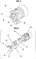
Fig. 3 is a perspective view of a focus adjust collimator unit. -
Fig. 4 is a perspective view of a combined lens housing and inner collimator housing assembly. -
Fig. 5 is an exploded perspective view ofFig. 4 . -
Fig. 6 is a cross sectional view along line 6-6 inFig. 3 . -
Fig. 7 is an illustrative diagram of the asymmetric force loading according to the present system and method. - Reference will now be made in detail to several embodiments of the disclosure that are illustrated in the accompanying drawings. The drawings are in simplified form and are not to precise scale. The words "connect," "couple," and similar terms with their inflectional morphemes do not necessarily denote direct and immediate connections, but also include connections through mediate elements or devices.
- Turning first to
Figs. 3 through 7 , there is shown a focus adjustcollimator 20 having an outercollimator housing assembly 23 and an innercollimator housing assembly 24. Focus adjustcollimator 20 adaptively receives a fiber laser (not shown along direction A (Fig. 6 ) during a use requiring an alignment of the fiber laser with a second fiber laser (also not shown). Innercollimator housing assembly 24 includes alens housing 29 and a coupler housing assembly 30 (seeFig. 5 ), and is provided with a focus adjustlever portion 22 of split-arm yoke 26 operable and adjustable relative to apivot 25. Focus adjustlever 22 may be provided in any adaptive configuration but is shown here as part of split-arm yoke 26 configuration having at least one ball ended setscrew 21 as an adjustable contact member at a distal endproximate lens housing 29. Focus adjustlever 22 may also be in a single-arm shape, a curved shape (not shown), or even a circular yoke shape (all not shown) sufficient to allow adjustlever 22 to operate relative tolens housing 29 to provide both an asymmetric binding force thereto during use thus preventing misalignment of X and Y adjustments, and while allowing sliding Z axis movement with little effort. -
Lens housing 29 is slidable withincoupler housing assembly 30 relative to a beam direction A and has a very close tolerance therein. A plurality ofcompression springs 31 provide a uniform urging force betweencoupler housing assembly 30 and an inner surface of a protruding annular portion oflens housing 29, following assembly. A hardenedring member 27, as a force bearing member, is on an outer surface of the protruding annular portion in a force bearing contact with ends of one or more ball ended setscrews 21 to receive a contact therefrom. Setscrews 21 are threadably adjustable within apertures ofyoke 26 on focus adjustlever 22 to provide an operative asymmetrical adjustment and contact relative to hardenedring 27. Either or both setscrews 21 may be adaptively used to contact hardenedring 27 onlens housing 29 and exert force thereon. If the screw positions are off center (Fig. 7 ) relative to a center line oflens housing 29, then either or both screws may be used to induce asymmetrical loading (a bind). Where the screw positions are aligned with a center line (Fig. 6 ) then only one screw may be used to induce asymmetrical loading (force application). In either operation the mechanism is aided by the set ofcompression springs 31 to cause an urging pressure to operatively resist that exerted by focus adjustlever 22. Focus adjustlever 22 is pivotaby operative about apivot 25 via a fine pitch adjustment screw andbushing assembly 28 inouter housing 23 accessible via a access opening 32 in outer collimator housing 23 (Fig. 6 ). During a use, asassembly 28 is adjustedlever 22moves lens housing 29 linearly in the Z axis direction without change in the X and Y axis relative to fiber laser axis A. - Referring to illustrative diagram
Fig. 7 , the asymmetrical loading mechanism provides a preloaded linear movement in a pressure force (PF) onlens housing 29 relative to a center line causing a very slight off-center misalignment force (B1) and a responsive binding force (B2) whenlens housing 29 binds incoupler housing assembly 30 thereby preventing misalignment of an X axis and Y axis adjustment while allowing a linear Z axis movement relative tocoupler housing assembly 30. The off-center force (B1) and responsive binding force (B2) are related to pressure force (PF) which, in turn, is the result of a screw force (SF) exerted along focus adjustlever portion 22 ofyoke 26 according to the configuration and arrangement of the proposed disclosure. The resulting 'bind' condition is the result of contact between an outer surface of lens housing 39 and an inner surface ofcoupler housing assembly 30. This contact provides a friction resistance to change in X and Y axis direction while allowing a sliding Z axis adjustment. Therefore, during use the binding force is releasable and adjustable as needed by a user. - Those of skill in the art will recognize that modifying the geometry and length of
lever portion 22,yoke 26, distance ofscrew 21 contact from the centerline, and other elements of the present disclosure allow relative adaption. - Those of skill in the art will further recognize that the proposed beam coupler alignment system further supports a method for beam coupler alignment. In use, a fiber laser (not shown) is inserted in a bayonet type mechanism along direction A (
Fig. 6 ) in a focus adjustcollimator assembly 20. Innercollimator housing assembly 24 is configured with acoupler housing assembly 30 and a lens housing operably adjustable relative thereto with focus adjustlever 22, as discussed above. Thus, in a first step following insertion of a fiber laser, an X and Y axis adjustment occurs. Third, the focus adjustlever 22 mechanism is used to apply an asymmetric force on lens housing creating a slight bind condition to eliminate further X and Y axis movement. Forth, focus adjust lever is operated to adjust Z axis focus. - Those of skill in the art will recognize that the proposed disclosure provides an asymmetric alignment mechanism or system configured and arranged to align a collimator unit of a fiber laser system about a desired central axis using an asymmetric practice. Those of skill in the art will also recognize that the proposed disclosure provides a system for aligning an input collimator assembly and an output collimator assembly about a common central axis in a fiber laser system in a time-efficient manner. Those of skill in the art will further recognize that the phrase asymmetric will be broadly understood to indicate application of a force off the center of the housing thus inducing asymmetrical loading.
Claims (10)
- A focus adjustable collimator unit for a fiber laser, comprising:an outer housing (23) configured to secure an optical fiber thereto;an inner housing (24) received within the outer housing (23);the inner housing (24) further comprising a concentric coupler housing assembly (30) having an inner surface and an adjustably retained lens housing (29) having an outer surface received therein; an asymmetric adjustment mechanism (21, 22, 25, 28) configured and arranged between the outer housing (23) and the lens housing (29) to releasably and adjustably bind the lens housing (29) relative to the inner surface of the coupler housing assembly (30) during a focus alignment of the system resulting of a contact between the outer surface of the lens housing (29) and the inner surface of the coupler housing assembly (30), whereby this contact provides a friction resistance to change in an X and Y axis direction while allowing a sliding Z axis focus adjustment; the focus adjustable collimator unit being characterised in that the asymmetric adjustment mechanism comprises a pivot mechanism in the asymmetric adjustment mechanism (21, 22, 25, 28); the pivot mechanism pivotably coupled to the coupler housing assembly (30) and arranged to adjustably urge the lens housing (29) in an asymmetric direction during the focus alignment.
- The focus adjustable collimator unit of claim 1 further comprising:
a spring assembly mechanism configured between the lens housing and the coupler housing assembly to provide a separation urging between the coupler housing assembly and the lens housing. - The focus adjustable collimator unit of claim 1 further comprising:
at least one yoke member extending from the pivot mechanism away from a pivot point proximate the coupler housing assembly toward an outer edge of the lens housing. - The focus adjustable collimator unit of claim 3 further comprising:
at least one contact member adjustably extending from the yoke member in a contact direction relative to the outer edge of the lens housing. - The focus adjustable collimator unit of claim 4 further comprising:
a threadable adjustment mechanism coupled to the pivot mechanism distant from the yoke member arranged to adjust the pivot mechanism relative to the outer housing during the focus alignment of the system. - A method for adjusting a collimator unit for a fiber laser, comprising the steps of:securing an optical fiber to an outer housing (23);the outer housing (23) further comprising an inner housing (24) received therein andthe inner housing (24) further comprising:a concentric coupler housing assembly (30) having an inner surface and an adjustably retained lens housing (29) having an outer surface received therein relative to a common central axis; andan asymmetric adjustment mechanism (21, 22, 25, 28) configured and arranged between the outer housing (23) and the lens housing (29) to adjustably bind the lens housing (29) relative to the coupler housing assembly (30) during an alignment of the system in an asymmetric manner whereby a contact between the outer surface of the lens housing (29) and the inner surface of the coupler housing assembly (30) provides a friction resistance to change in an X and Y axis direction while allowing a sliding Z axis focus adjustment;adjusting the X axis alignment;adjusting the Y axis alignment;operating the asymmetric adjustment mechanism (21, 22, 25, 28) to place the lens housing (29) in a releasable bind position on the inner surface of the coupler housing (30) so as to fix the X axis adjustment and the Y axis adjustment the method being characterised in that the steps of operating the asymmetric adjustment mechanism (21, 22, 25, 28) further comprise the step of adjusting at least one contact member (28) relative to a pivot arm member (22) pivotably coupled to the coupler housing assembly (30) and applying a force to a side portion of the lens housing (29) in an asymmetric manner relative to the central axis; and adjusting the Z axis alignment to achieve a focus of the fiber laser, whereby the method enables a concentric alignment of an output of the fiber laser with the lens housing (29) in a simple manner.
- The method for adjusting a collimator unit of claim 6, wherein:
the step of operating further comprises the step of:
threadably applying a pivot force applied to the pivot arm relative to the outer housing. - The method for adjusting a collimator unit of claim 6 further comprising the steps of:arranging a spring assembly between the lens housing about an inner lip thereof and an outer portion of the coupler housing assembly; andduring the step of adjusting the Z axis providing, with the spring assembly, an urging between the coupler housing assembly and the lens housing to resist the adjustment.
- The method for adjusting a collimator of claim 6, wherein:
the step of operating the adjustment mechanism to place the lens housing in a releasable bind position includes a step of moving the lens in an asymmetric manner. - The method for adjusting a collimator of claim 9, further comprising the steps of:releasing the bind position of the lens in the coupler housing;readjusting an X axis alignment;readjusting a Y axis alignment;reengaging the adjustment mechanism to place the lens housing in the releasable bind position; andreadjusting a Z axis alignment to achieve a focus.
Applications Claiming Priority (1)
| Application Number | Priority Date | Filing Date | Title |
|---|---|---|---|
| PCT/US2011/025012 WO2012112146A1 (en) | 2011-02-16 | 2011-02-16 | Beam coupler alignment system and method |
Publications (3)
| Publication Number | Publication Date |
|---|---|
| EP2676341A1 EP2676341A1 (en) | 2013-12-25 |
| EP2676341A4 EP2676341A4 (en) | 2014-09-03 |
| EP2676341B1 true EP2676341B1 (en) | 2020-06-03 |
Family
ID=46672857
Family Applications (1)
| Application Number | Title | Priority Date | Filing Date |
|---|---|---|---|
| EP11858874.8A Active EP2676341B1 (en) | 2011-02-16 | 2011-02-16 | Beam coupler alignment system and method |
Country Status (2)
| Country | Link |
|---|---|
| EP (1) | EP2676341B1 (en) |
| WO (1) | WO2012112146A1 (en) |
Families Citing this family (8)
| Publication number | Priority date | Publication date | Assignee | Title |
|---|---|---|---|---|
| WO2015106139A1 (en) * | 2014-01-10 | 2015-07-16 | Freedom Scientific, Inc. | Handheld magnifier camera with variable focus distance |
| EP3293554B1 (en) | 2016-09-13 | 2023-03-15 | Schott Ag | Device and method for aligning a light beam |
| DE102016117202B4 (en) | 2016-09-13 | 2021-04-01 | Schott Ag | Apparatus and method for aligning a light beam |
| DE102017205590B3 (en) * | 2017-04-03 | 2017-12-14 | Asphericon Gmbh | Adjustable fiber collimator and method for its assembly |
| CN111458802B (en) * | 2020-05-06 | 2024-02-13 | 武汉锐科光纤激光技术股份有限公司 | Light beam coupling device and coupling method thereof |
| CN112327502B (en) * | 2020-09-28 | 2022-07-19 | 南京核安核能科技有限公司 | Detector collimator with opening adjustment |
| CN216096959U (en) * | 2021-11-02 | 2022-03-22 | 东莞市昂图智能科技有限公司 | Foldable anti-loss fast-focusing laser device |
| CN113791472A (en) * | 2021-11-18 | 2021-12-14 | 之江实验室 | A fiber optic coupler that can be precisely adjusted in multiple dimensions |
Citations (1)
| Publication number | Priority date | Publication date | Assignee | Title |
|---|---|---|---|---|
| US5613168A (en) * | 1994-04-15 | 1997-03-18 | Asahi Kogaku Kogyo Kabushiki Kaisha | Apparatus for adjusting position of lens in camera |
Family Cites Families (4)
| Publication number | Priority date | Publication date | Assignee | Title |
|---|---|---|---|---|
| US6678447B1 (en) * | 2001-07-03 | 2004-01-13 | Valyn International | Adjustable multi-beam splitter and fiber coupler |
| KR20080065250A (en) * | 2007-01-08 | 2008-07-11 | 양동운 | Collimator for Free Space Optical Communication |
| US8014641B2 (en) * | 2008-12-31 | 2011-09-06 | Yuri Grapov | Beam coupler |
| US7794159B2 (en) * | 2008-12-31 | 2010-09-14 | Yuri Grapov | Sealed beam coupler for an isolated environment |
-
2011
- 2011-02-16 EP EP11858874.8A patent/EP2676341B1/en active Active
- 2011-02-16 WO PCT/US2011/025012 patent/WO2012112146A1/en not_active Ceased
Patent Citations (1)
| Publication number | Priority date | Publication date | Assignee | Title |
|---|---|---|---|---|
| US5613168A (en) * | 1994-04-15 | 1997-03-18 | Asahi Kogaku Kogyo Kabushiki Kaisha | Apparatus for adjusting position of lens in camera |
Also Published As
| Publication number | Publication date |
|---|---|
| EP2676341A4 (en) | 2014-09-03 |
| EP2676341A1 (en) | 2013-12-25 |
| WO2012112146A1 (en) | 2012-08-23 |
Similar Documents
| Publication | Publication Date | Title |
|---|---|---|
| WO2012112146A1 (en) | Beam coupler alignment system and method | |
| US7764856B2 (en) | Device for injecting light into an optical wave guide | |
| US9557489B2 (en) | Optoelectronic component | |
| EP3644102B1 (en) | Mirror, grating and lens system for coupling light | |
| JP2015530626A (en) | Optical connector | |
| JP2004501400A (en) | Optical signal transmission equipment | |
| US9782063B2 (en) | Optical coupling efficiency detection assembly and method of assembling the same | |
| CN101441311A (en) | Reflection mirror apparatus | |
| US6647173B2 (en) | Optical switch with a moveable optical component | |
| AU6239099A (en) | Fiber coupler variable optical attenuator | |
| CN111308677B (en) | A beam position adjustment device | |
| US10182275B1 (en) | Passive optical subassembly with a signal pitch router | |
| US8913861B2 (en) | Beam coupler alignment system and method | |
| WO2023138026A1 (en) | Tunable optical filter and light channel monitoring module | |
| CN105842791A (en) | Adjustable double-fiber collimator and application thereof | |
| EP3344959B1 (en) | Sub-micron alignment of a monitoring fiber for optical feedback in an ophthalmic endo-illumination system | |
| JP2017116729A (en) | Eccentricity adjustment structure and optical instrument | |
| US6665462B2 (en) | Optical switch | |
| US6321022B1 (en) | Thermally compensated variable optical attenuator with displacement mechanism | |
| JP5546410B2 (en) | Optical member, optical communication module using the same, and alignment method | |
| KR102831487B1 (en) | Beam expander and method for operating the beam expander | |
| WO2004015458A3 (en) | Optical switch assembly | |
| US7321706B2 (en) | Optical fiber coupler | |
| JP5066038B2 (en) | Optical path length adjustment device | |
| US20170139159A1 (en) | Optical module and method for manufacturing the optical module |
Legal Events
| Date | Code | Title | Description |
|---|---|---|---|
| PUAI | Public reference made under article 153(3) epc to a published international application that has entered the european phase |
Free format text: ORIGINAL CODE: 0009012 |
|
| 17P | Request for examination filed |
Effective date: 20130723 |
|
| AK | Designated contracting states |
Kind code of ref document: A1 Designated state(s): AL AT BE BG CH CY CZ DE DK EE ES FI FR GB GR HR HU IE IS IT LI LT LU LV MC MK MT NL NO PL PT RO RS SE SI SK SM TR |
|
| DAX | Request for extension of the european patent (deleted) | ||
| A4 | Supplementary search report drawn up and despatched |
Effective date: 20140805 |
|
| RIC1 | Information provided on ipc code assigned before grant |
Ipc: H01S 5/026 20060101ALI20140730BHEP Ipc: G02B 6/32 20060101ALN20140730BHEP Ipc: H01S 5/02 20060101ALI20140730BHEP Ipc: H01S 3/10 20060101AFI20140730BHEP Ipc: G02B 7/02 20060101ALN20140730BHEP |
|
| STAA | Information on the status of an ep patent application or granted ep patent |
Free format text: STATUS: EXAMINATION IS IN PROGRESS |
|
| 17Q | First examination report despatched |
Effective date: 20181108 |
|
| RIC1 | Information provided on ipc code assigned before grant |
Ipc: G02B 6/32 20060101ALN20191204BHEP Ipc: H01S 5/02 20060101ALI20191204BHEP Ipc: G02B 7/02 20060101ALN20191204BHEP Ipc: H01S 3/10 20060101AFI20191204BHEP Ipc: H01S 5/026 20060101ALI20191204BHEP |
|
| GRAP | Despatch of communication of intention to grant a patent |
Free format text: ORIGINAL CODE: EPIDOSNIGR1 |
|
| STAA | Information on the status of an ep patent application or granted ep patent |
Free format text: STATUS: GRANT OF PATENT IS INTENDED |
|
| INTG | Intention to grant announced |
Effective date: 20200110 |
|
| GRAS | Grant fee paid |
Free format text: ORIGINAL CODE: EPIDOSNIGR3 |
|
| GRAA | (expected) grant |
Free format text: ORIGINAL CODE: 0009210 |
|
| STAA | Information on the status of an ep patent application or granted ep patent |
Free format text: STATUS: THE PATENT HAS BEEN GRANTED |
|
| AK | Designated contracting states |
Kind code of ref document: B1 Designated state(s): AL AT BE BG CH CY CZ DE DK EE ES FI FR GB GR HR HU IE IS IT LI LT LU LV MC MK MT NL NO PL PT RO RS SE SI SK SM TR |
|
| REG | Reference to a national code |
Ref country code: GB Ref legal event code: FG4D |
|
| REG | Reference to a national code |
Ref country code: AT Ref legal event code: REF Ref document number: 1278012 Country of ref document: AT Kind code of ref document: T Effective date: 20200615 Ref country code: CH Ref legal event code: EP |
|
| REG | Reference to a national code |
Ref country code: DE Ref legal event code: R096 Ref document number: 602011067193 Country of ref document: DE |
|
| REG | Reference to a national code |
Ref country code: LT Ref legal event code: MG4D |
|
| PG25 | Lapsed in a contracting state [announced via postgrant information from national office to epo] |
Ref country code: FI Free format text: LAPSE BECAUSE OF FAILURE TO SUBMIT A TRANSLATION OF THE DESCRIPTION OR TO PAY THE FEE WITHIN THE PRESCRIBED TIME-LIMIT Effective date: 20200603 Ref country code: NO Free format text: LAPSE BECAUSE OF FAILURE TO SUBMIT A TRANSLATION OF THE DESCRIPTION OR TO PAY THE FEE WITHIN THE PRESCRIBED TIME-LIMIT Effective date: 20200903 Ref country code: GR Free format text: LAPSE BECAUSE OF FAILURE TO SUBMIT A TRANSLATION OF THE DESCRIPTION OR TO PAY THE FEE WITHIN THE PRESCRIBED TIME-LIMIT Effective date: 20200904 Ref country code: LT Free format text: LAPSE BECAUSE OF FAILURE TO SUBMIT A TRANSLATION OF THE DESCRIPTION OR TO PAY THE FEE WITHIN THE PRESCRIBED TIME-LIMIT Effective date: 20200603 Ref country code: SE Free format text: LAPSE BECAUSE OF FAILURE TO SUBMIT A TRANSLATION OF THE DESCRIPTION OR TO PAY THE FEE WITHIN THE PRESCRIBED TIME-LIMIT Effective date: 20200603 |
|
| REG | Reference to a national code |
Ref country code: NL Ref legal event code: MP Effective date: 20200603 |
|
| PG25 | Lapsed in a contracting state [announced via postgrant information from national office to epo] |
Ref country code: BG Free format text: LAPSE BECAUSE OF FAILURE TO SUBMIT A TRANSLATION OF THE DESCRIPTION OR TO PAY THE FEE WITHIN THE PRESCRIBED TIME-LIMIT Effective date: 20200903 Ref country code: HR Free format text: LAPSE BECAUSE OF FAILURE TO SUBMIT A TRANSLATION OF THE DESCRIPTION OR TO PAY THE FEE WITHIN THE PRESCRIBED TIME-LIMIT Effective date: 20200603 Ref country code: RS Free format text: LAPSE BECAUSE OF FAILURE TO SUBMIT A TRANSLATION OF THE DESCRIPTION OR TO PAY THE FEE WITHIN THE PRESCRIBED TIME-LIMIT Effective date: 20200603 Ref country code: LV Free format text: LAPSE BECAUSE OF FAILURE TO SUBMIT A TRANSLATION OF THE DESCRIPTION OR TO PAY THE FEE WITHIN THE PRESCRIBED TIME-LIMIT Effective date: 20200603 |
|
| REG | Reference to a national code |
Ref country code: AT Ref legal event code: MK05 Ref document number: 1278012 Country of ref document: AT Kind code of ref document: T Effective date: 20200603 |
|
| PG25 | Lapsed in a contracting state [announced via postgrant information from national office to epo] |
Ref country code: AL Free format text: LAPSE BECAUSE OF FAILURE TO SUBMIT A TRANSLATION OF THE DESCRIPTION OR TO PAY THE FEE WITHIN THE PRESCRIBED TIME-LIMIT Effective date: 20200603 Ref country code: NL Free format text: LAPSE BECAUSE OF FAILURE TO SUBMIT A TRANSLATION OF THE DESCRIPTION OR TO PAY THE FEE WITHIN THE PRESCRIBED TIME-LIMIT Effective date: 20200603 |
|
| PG25 | Lapsed in a contracting state [announced via postgrant information from national office to epo] |
Ref country code: SM Free format text: LAPSE BECAUSE OF FAILURE TO SUBMIT A TRANSLATION OF THE DESCRIPTION OR TO PAY THE FEE WITHIN THE PRESCRIBED TIME-LIMIT Effective date: 20200603 Ref country code: EE Free format text: LAPSE BECAUSE OF FAILURE TO SUBMIT A TRANSLATION OF THE DESCRIPTION OR TO PAY THE FEE WITHIN THE PRESCRIBED TIME-LIMIT Effective date: 20200603 Ref country code: ES Free format text: LAPSE BECAUSE OF FAILURE TO SUBMIT A TRANSLATION OF THE DESCRIPTION OR TO PAY THE FEE WITHIN THE PRESCRIBED TIME-LIMIT Effective date: 20200603 Ref country code: AT Free format text: LAPSE BECAUSE OF FAILURE TO SUBMIT A TRANSLATION OF THE DESCRIPTION OR TO PAY THE FEE WITHIN THE PRESCRIBED TIME-LIMIT Effective date: 20200603 Ref country code: PT Free format text: LAPSE BECAUSE OF FAILURE TO SUBMIT A TRANSLATION OF THE DESCRIPTION OR TO PAY THE FEE WITHIN THE PRESCRIBED TIME-LIMIT Effective date: 20201006 Ref country code: RO Free format text: LAPSE BECAUSE OF FAILURE TO SUBMIT A TRANSLATION OF THE DESCRIPTION OR TO PAY THE FEE WITHIN THE PRESCRIBED TIME-LIMIT Effective date: 20200603 Ref country code: IT Free format text: LAPSE BECAUSE OF FAILURE TO SUBMIT A TRANSLATION OF THE DESCRIPTION OR TO PAY THE FEE WITHIN THE PRESCRIBED TIME-LIMIT Effective date: 20200603 Ref country code: CZ Free format text: LAPSE BECAUSE OF FAILURE TO SUBMIT A TRANSLATION OF THE DESCRIPTION OR TO PAY THE FEE WITHIN THE PRESCRIBED TIME-LIMIT Effective date: 20200603 |
|
| PG25 | Lapsed in a contracting state [announced via postgrant information from national office to epo] |
Ref country code: IS Free format text: LAPSE BECAUSE OF FAILURE TO SUBMIT A TRANSLATION OF THE DESCRIPTION OR TO PAY THE FEE WITHIN THE PRESCRIBED TIME-LIMIT Effective date: 20201003 Ref country code: SK Free format text: LAPSE BECAUSE OF FAILURE TO SUBMIT A TRANSLATION OF THE DESCRIPTION OR TO PAY THE FEE WITHIN THE PRESCRIBED TIME-LIMIT Effective date: 20200603 Ref country code: PL Free format text: LAPSE BECAUSE OF FAILURE TO SUBMIT A TRANSLATION OF THE DESCRIPTION OR TO PAY THE FEE WITHIN THE PRESCRIBED TIME-LIMIT Effective date: 20200603 |
|
| REG | Reference to a national code |
Ref country code: DE Ref legal event code: R097 Ref document number: 602011067193 Country of ref document: DE |
|
| PLBE | No opposition filed within time limit |
Free format text: ORIGINAL CODE: 0009261 |
|
| STAA | Information on the status of an ep patent application or granted ep patent |
Free format text: STATUS: NO OPPOSITION FILED WITHIN TIME LIMIT |
|
| PG25 | Lapsed in a contracting state [announced via postgrant information from national office to epo] |
Ref country code: DK Free format text: LAPSE BECAUSE OF FAILURE TO SUBMIT A TRANSLATION OF THE DESCRIPTION OR TO PAY THE FEE WITHIN THE PRESCRIBED TIME-LIMIT Effective date: 20200603 |
|
| 26N | No opposition filed |
Effective date: 20210304 |
|
| PG25 | Lapsed in a contracting state [announced via postgrant information from national office to epo] |
Ref country code: SI Free format text: LAPSE BECAUSE OF FAILURE TO SUBMIT A TRANSLATION OF THE DESCRIPTION OR TO PAY THE FEE WITHIN THE PRESCRIBED TIME-LIMIT Effective date: 20200603 |
|
| PG25 | Lapsed in a contracting state [announced via postgrant information from national office to epo] |
Ref country code: MC Free format text: LAPSE BECAUSE OF FAILURE TO SUBMIT A TRANSLATION OF THE DESCRIPTION OR TO PAY THE FEE WITHIN THE PRESCRIBED TIME-LIMIT Effective date: 20200603 |
|
| GBPC | Gb: european patent ceased through non-payment of renewal fee |
Effective date: 20210216 |
|
| REG | Reference to a national code |
Ref country code: BE Ref legal event code: MM Effective date: 20210228 |
|
| PG25 | Lapsed in a contracting state [announced via postgrant information from national office to epo] |
Ref country code: LU Free format text: LAPSE BECAUSE OF NON-PAYMENT OF DUE FEES Effective date: 20210216 Ref country code: LI Free format text: LAPSE BECAUSE OF NON-PAYMENT OF DUE FEES Effective date: 20210228 Ref country code: CH Free format text: LAPSE BECAUSE OF NON-PAYMENT OF DUE FEES Effective date: 20210228 |
|
| PG25 | Lapsed in a contracting state [announced via postgrant information from national office to epo] |
Ref country code: GB Free format text: LAPSE BECAUSE OF NON-PAYMENT OF DUE FEES Effective date: 20210216 Ref country code: IE Free format text: LAPSE BECAUSE OF NON-PAYMENT OF DUE FEES Effective date: 20210216 Ref country code: FR Free format text: LAPSE BECAUSE OF NON-PAYMENT OF DUE FEES Effective date: 20210228 |
|
| PG25 | Lapsed in a contracting state [announced via postgrant information from national office to epo] |
Ref country code: BE Free format text: LAPSE BECAUSE OF NON-PAYMENT OF DUE FEES Effective date: 20210228 |
|
| PG25 | Lapsed in a contracting state [announced via postgrant information from national office to epo] |
Ref country code: HU Free format text: LAPSE BECAUSE OF FAILURE TO SUBMIT A TRANSLATION OF THE DESCRIPTION OR TO PAY THE FEE WITHIN THE PRESCRIBED TIME-LIMIT; INVALID AB INITIO Effective date: 20110216 Ref country code: CY Free format text: LAPSE BECAUSE OF FAILURE TO SUBMIT A TRANSLATION OF THE DESCRIPTION OR TO PAY THE FEE WITHIN THE PRESCRIBED TIME-LIMIT Effective date: 20200603 |
|
| P01 | Opt-out of the competence of the unified patent court (upc) registered |
Effective date: 20230516 |
|
| PG25 | Lapsed in a contracting state [announced via postgrant information from national office to epo] |
Ref country code: MK Free format text: LAPSE BECAUSE OF FAILURE TO SUBMIT A TRANSLATION OF THE DESCRIPTION OR TO PAY THE FEE WITHIN THE PRESCRIBED TIME-LIMIT Effective date: 20200603 |
|
| PG25 | Lapsed in a contracting state [announced via postgrant information from national office to epo] |
Ref country code: TR Free format text: LAPSE BECAUSE OF FAILURE TO SUBMIT A TRANSLATION OF THE DESCRIPTION OR TO PAY THE FEE WITHIN THE PRESCRIBED TIME-LIMIT Effective date: 20200603 |
|
| PG25 | Lapsed in a contracting state [announced via postgrant information from national office to epo] |
Ref country code: MT Free format text: LAPSE BECAUSE OF FAILURE TO SUBMIT A TRANSLATION OF THE DESCRIPTION OR TO PAY THE FEE WITHIN THE PRESCRIBED TIME-LIMIT Effective date: 20200603 |
|
| PGFP | Annual fee paid to national office [announced via postgrant information from national office to epo] |
Ref country code: DE Payment date: 20260121 Year of fee payment: 16 |