EP2676002B1 - Turbine tip clearance measurement - Google Patents
Turbine tip clearance measurement Download PDFInfo
- Publication number
- EP2676002B1 EP2676002B1 EP12706367.5A EP12706367A EP2676002B1 EP 2676002 B1 EP2676002 B1 EP 2676002B1 EP 12706367 A EP12706367 A EP 12706367A EP 2676002 B1 EP2676002 B1 EP 2676002B1
- Authority
- EP
- European Patent Office
- Prior art keywords
- body member
- facing side
- blades
- indicia
- seal
- Prior art date
- Legal status (The legal status is an assumption and is not a legal conclusion. Google has not performed a legal analysis and makes no representation as to the accuracy of the status listed.)
- Not-in-force
Links
- 238000005259 measurement Methods 0.000 title claims description 27
- 230000000007 visual effect Effects 0.000 claims description 7
- 238000000034 method Methods 0.000 claims description 4
- 238000009434 installation Methods 0.000 description 5
- 239000000463 material Substances 0.000 description 4
- 229920003223 poly(pyromellitimide-1,4-diphenyl ether) Polymers 0.000 description 4
- 229920001721 polyimide Polymers 0.000 description 4
- 239000000523 sample Substances 0.000 description 4
- 239000000853 adhesive Substances 0.000 description 3
- 230000001070 adhesive effect Effects 0.000 description 3
- 239000007789 gas Substances 0.000 description 3
- 239000009719 polyimide resin Substances 0.000 description 3
- 230000005484 gravity Effects 0.000 description 2
- 238000007689 inspection Methods 0.000 description 2
- 230000002093 peripheral effect Effects 0.000 description 2
- 239000004593 Epoxy Substances 0.000 description 1
- 239000004642 Polyimide Substances 0.000 description 1
- 238000005299 abrasion Methods 0.000 description 1
- 230000002411 adverse Effects 0.000 description 1
- 230000015572 biosynthetic process Effects 0.000 description 1
- 230000003247 decreasing effect Effects 0.000 description 1
- 239000012530 fluid Substances 0.000 description 1
- 230000007246 mechanism Effects 0.000 description 1
- 230000003287 optical effect Effects 0.000 description 1
- 238000011144 upstream manufacturing Methods 0.000 description 1
- 238000012795 verification Methods 0.000 description 1
Images

Classifications
-
- F—MECHANICAL ENGINEERING; LIGHTING; HEATING; WEAPONS; BLASTING
- F01—MACHINES OR ENGINES IN GENERAL; ENGINE PLANTS IN GENERAL; STEAM ENGINES
- F01D—NON-POSITIVE DISPLACEMENT MACHINES OR ENGINES, e.g. STEAM TURBINES
- F01D11/00—Preventing or minimising internal leakage of working-fluid, e.g. between stages
- F01D11/08—Preventing or minimising internal leakage of working-fluid, e.g. between stages for sealing space between rotor blade tips and stator
- F01D11/12—Preventing or minimising internal leakage of working-fluid, e.g. between stages for sealing space between rotor blade tips and stator using a rubstrip, e.g. erodible. deformable or resiliently-biased part
- F01D11/122—Preventing or minimising internal leakage of working-fluid, e.g. between stages for sealing space between rotor blade tips and stator using a rubstrip, e.g. erodible. deformable or resiliently-biased part with erodable or abradable material
-
- F—MECHANICAL ENGINEERING; LIGHTING; HEATING; WEAPONS; BLASTING
- F01—MACHINES OR ENGINES IN GENERAL; ENGINE PLANTS IN GENERAL; STEAM ENGINES
- F01D—NON-POSITIVE DISPLACEMENT MACHINES OR ENGINES, e.g. STEAM TURBINES
- F01D17/00—Regulating or controlling by varying flow
- F01D17/02—Arrangement of sensing elements
-
- G—PHYSICS
- G01—MEASURING; TESTING
- G01B—MEASURING LENGTH, THICKNESS OR SIMILAR LINEAR DIMENSIONS; MEASURING ANGLES; MEASURING AREAS; MEASURING IRREGULARITIES OF SURFACES OR CONTOURS
- G01B5/00—Measuring arrangements characterised by the use of mechanical techniques
- G01B5/14—Measuring arrangements characterised by the use of mechanical techniques for measuring distance or clearance between spaced objects or spaced apertures
-
- F—MECHANICAL ENGINEERING; LIGHTING; HEATING; WEAPONS; BLASTING
- F05—INDEXING SCHEMES RELATING TO ENGINES OR PUMPS IN VARIOUS SUBCLASSES OF CLASSES F01-F04
- F05D—INDEXING SCHEME FOR ASPECTS RELATING TO NON-POSITIVE-DISPLACEMENT MACHINES OR ENGINES, GAS-TURBINES OR JET-PROPULSION PLANTS
- F05D2240/00—Components
- F05D2240/10—Stators
- F05D2240/11—Shroud seal segments
Definitions
- the present invention relates generally to a measuring assembly for use in a turbine engine, and more particularly, to a measuring assembly for determining a clearance between an inner surface of a seal structure in a turbine engine and tips of blades mounted to a rotor in the engine.
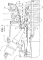
- a turbine engine 10 including a compressor section 12, a combustor section 14 and a turbine section 16.
- the turbine section 16 there are alternating rows of stationary airfoils 18 (commonly referred to as vanes) and rotating airfoils 20 (commonly referred to as blades).
- Each row of blades 20 is formed by a plurality of airfoils 20 attached to discs 22 forming a rotor 24.
- the blades 20 extend radially outward from the discs 22 and terminate in a region known as the blade tip 26.
- Each row of vanes 18 is formed by attaching a plurality of vanes 18 to a vane carrier 28.
- the vanes 18 extend radially inwardly from an inner peripheral surface 30 of the vane carrier 28.
- the vane carrier 28 is attached to an outer casing 32 to form an outer casing structure 34, which encloses the turbine section 16 of the engine 10.
- a ring seal assembly 36 can be attached to the inner peripheral surface 30 of the vane carrier 28.
- the seal assembly 36 is a stationary component that forms a portion of a hot gas path between the rows of vanes 18 at the locations of the rotating blades 20.
- the seal assembly 36 is commonly formed by a plurality of ring segments attached to the vane carrier 28.
- Each seal assembly 36 can substantially surround a row of blades 20 such that the tips 26 of the rotating blades 20 are in close proximity to the seal assembly 36.
- a clearance is usually defined between the tips 26 of the rotating blades 20 and an inner surface of the seal assembly 36.
- US 2003/0020496 A1 discloses measurement of the clearance between the tips of the blades of a ring of blades of a turbomachine and the interior wall of a casing of the turbomachine surrounding the ring of blades.
- a probe is mounted on the casing so as to extend radially.
- the radially inward end of the probe is made of a material that can be abraded by the tips of the blades as they rotate.
- a printed circuit is arranged on the probe and comprises a number of adjacent U-shaped electrical circuits. Bases of the adjacent U-shaped electrical circuits are arranged in the radially inward end of the probe and are abraded by the tips of the blades as they rotate.
- the bases lie at different depths from a reference level defining the interior wall of the casing. Means is provided for recognizing which U-shaped electrical circuits have been broken by abrasion and which remain intact.
- a first aspect of the present invention is specified in claim 1 of the following set of claims.
- a second aspect of the present invention is specified in claim 5 of the set of claims.
- a preferred feature of the second aspect of the present invention is specified in claim 6 of the set of claims.
- the outer casing structure 34 of the turbine section 16 may be formed as an upper casing structure half 38 and a lower casing structure half 40.
- Each of the casing structure halves 38, 40 may include respective halves of the outer casing 32, the vane carrier 28 and the seal assembly 36.
- the outer casing 32 may comprise upper and lower outer casing halves 32A, 32B supporting respective upper and lower halves 28A, 28B of the vane carrier 28.
- associated upper and lower halves 36A, 36B of the seal assembly 36 are formed by a plurality of seal segments 42 positioned in side-by-side relation around the inner surface 30 of the vane carrier 28.
- the upper and lower casing structure halves 38, 40 may include flanges 44 for connecting the casing structure halves 38, 40 together at horizontal joints 46 ( Fig. 3 ), such as by means of bolts 48 and/or other retaining mechanisms.
- flanges 44 for connecting the casing structure halves 38, 40 together at horizontal joints 46 ( Fig. 3 ), such as by means of bolts 48 and/or other retaining mechanisms.
- attachment of the casing structure halves 38, 40 together, such as by the bolts 48 may cause distortions to the outer casing 32 that may alter the clearance between the blade tips 26 and the inner surfaces 50 of the seal segments 42 (hereinafter referred to as tip-to-seal clearance).
- variations in the tip-to-seal clearance between a circumferential location at top-dead-center (TDC) and a circumferential location at bottom-dead-center (BDC) may occur as a result of rotor gravity deflection.
- rotor gravity deflection may cause a larger tip-to-seal clearance for the blades 20 at or near TDC than for the blades 20 at or near BDC.
- a measuring assembly 52 may be provided comprising, for example, one or more body members 54 that may be affixed to the inner surface 50 of one or more of the seal segments 42.
- the seal assembly 52 is configured to be cut or abraded by at least one of the blade tips 26 to provide an indication of the tip-to-seal clearance after the outer casing structure 34 has been assembled. It may be noted that, for the purposes of the present invention, the terms "cut” and 'abrade” or “abraded” are considered to refer to equivalent operations and may be used interchangeably.
- the body member 54 may comprise a wedge shaped member having a first end 56, a second end 58, an outwardly facing side 60 extending between the first and second ends 56, 58, an inwardly facing side 62 extending between the first and second ends 56, 58 and opposite from the outwardly facing side 60, and a pair of lateral sides 64, 66 extending between the first and second ends 56, 58.
- the outwardly facing side 60 extends widthwise between the lateral sides 64, 66 and is rigidly affixed to the inner surface 50 of a seal segment 42, such as by means of a strong adhesive, e.g., an epoxy.
- the inwardly facing side 62 extends widthwise between the lateral sides 64, 66, and comprises a surface that extends at an angle relative to the inner surface 50 of the seal segment 42.
- the inwardly facing side 62 extends progressively radially inwardly from the first end 56 toward the second end 58.
- the inwardly facing side 62 is shown as a continuous ramp surface extending from the first end 56 to the second end 58.
- the inwardly facing side 62 may comprise other configurations including, for example, a discontinuous ramp surface, such as a ramp surface that extends radially inwardly in a stepwise manner.
- the body member 54 defines an indicia portion 68 extending radially inwardly from the inner surface 50 of the seal segment 42 to a location that may be located radially inwardly from the blade tips 26, see Figs. 3 and 7 .
- the indicia portion 68 may include a portion or section 70 that may be abraded or otherwise removed by the blades 20 during a rotational movement of the rotor 24 and blades 20 to provide a visual indication of the tip-to-seal clearance.
- the body member 54 may function as a distance gage between the inner surface 50 of the seal segment 42 and the blade tips 26 to provide a visual indication of the tip-to-seal clearance, as indicated by a radial extension or distance from the outer surface 60 to a cut or abraded portion 72 comprising a surface formed on the body member 54 when a portion of the inner side 62 is cut or abraded away by the blades 20 during a rotation operation performed on the rotor 24 following assembly of the outer casing structure 34, as is described below.
- a distance indicated by the indicia portion 68 may comprise a visually observable portion of the body member 54, e.g., on a lateral side 64, 66 or on the inwardly facing side 62, to provide an observable indication of the distance from the inner surface 50 to the cut or abraded portion 72, which may correspond to the radial location of the blade tips 26.
- the body member 54 may be formed of a material that may be readily cut or abraded by relative movement of the blade tips 26 across the body member 54 without causing the body member 54 to crack or otherwise deteriorate beyond the location of the cut or abraded portion 72 directly contacted by the blade tips 26.
- the body member 54 may preferably be formed of a polyimide material sold under the trademark VESPEL®.
- VESPEL® is a registered trademark of the E. I. DuPont de Nemours Company, used to describe a polyimide resin available from the E. I. DuPont de Nemours Company.
- a body member 54 formed of VESPEL® polyimide resin may be easily machined to accurate dimensions, and provide a durable material that permits the cut or abraded portion 72 to be accurately formed at the location of the blade tips 26 while the remainder of the body portion 54 is substantially undeformed and otherwise unaffected, and further will burn off of the seal segment 42 upon exposure to the hot working gases passing through the turbine section 16, so as to not adversely affect operation of the engine 10.
- the indicia portion 68 may include a plurality of indicia 74, at least some of which extend radially inwardly of the tips 26 of the blades 20 to facilitate a determination of a radial distance of the cut or abraded portion 72 from the inner surface 50.
- the indicia 74 may comprise a plurality of generally parallel line marks or grooves that may provide a visual indication of locations spaced along the body member 54 in a direction from the first end 56 toward the second end 58.
- the indicia 74 may provide a graduated measurement scale, where the locations of the indicia 74 correspond to predetermined radial measurement locations, i.e., radial distances, from the outwardly facing side 60 to the inwardly facing side 62.
- the distance from the outwardly facing side 60 to the inwardly facing side 62 at the second end 58 may be about 4.0 mm, and the indicia 74 may be spaced at locations along one or both of the lateral sides 64, 66 corresponding to 0.5 mm increments of the radial measurement locations along the ramp surface defined by the inwardly facing side 62.
- indicia 74a may correspond to a radial measurement location of 3.5 mm
- indicia 74b may correspond to a radial measurement location of 3.0 mm
- indicia 74c may correspond to a radial measurement location of 2.5 mm.
- the radial distance between the inner surface 50 of the seal segment 42 and the blade tips 26 may be determined by identifying an intersection location 76 ( Fig. 6 ) where the ramp surface defined by the inwardly facing side 62 intersects the cut or abraded portion 72 with reference to the particular indicia 74 that is nearest to the intersection location 76.
- the distance from the outwardly facing side 60 to the inwardly facing side 62 at the second end 58 of the body member 54 is selected such that the inwardly facing side 62 extends to a radial location within the turbine section 16 that is radially inwardly from the tips 26 of the blades 20 when the rotor 24 is installed in the turbine section 16.
- the final installed height, i.e., the radial inward extension, of the body member 54 may include a thickness of an adhesive used to affix the body member to the seal segment 42, such that the radial inward extension may be a combined height of the adhesive thickness and the distance from the outwardly facing side 60 to the inwardly facing side 62.
- the grooves may be painted, or otherwise coated, with a contrasting color relative to the color of the lateral sides 64, 66.
- the lateral sides 64, 66 may be painted, or otherwise coated, with a contrasting color to the body member 54 prior to forming grooves defining the indicia 74, such that indicia appear with a different or contrasting color relative to the lateral sides 64, 66 upon formation of the grooves.
- the measuring assembly 52 may be installed as a plurality of the body members 54 attached to the annular ring seal assembly 36 at a plurality of predetermined circumferential locations.
- the body members 54 are preferably attached to the seal segments 42 of the ring seal assembly 36 such that the first end 56 of the body member 54 is located upstream from the second end 58 of the body member 54, with reference to the direction of rotation of the rotor 24, positioning the inwardly facing side 62 to be initially contacted by a rotating blade 20 as the blade 20 rotates toward the second end 58 of the body member 54.
- the preferred implementation of the measuring assembly 52 is described with reference to a plurality of the body members 54, a form of the present invention may be performed using a single one of the body members 54.
- the plurality of body members 54 provide measurements at locations where different tip-to-seal clearances may occur around the circumference of the ring seal assembly 36.
- pairs of the body members 54 may be provided at the same location, i.e. on the same seal segment 42 or on adjacent seal segments 42, to provide a redundant measurement structure in case one of the body members 54 is damaged during installation of the rotor 24 or assembly of the outer casing structure 34.
- the plurality of predetermined circumferential measurement locations may be at or near top-dead-center and bottom-dead-center, and at or near each of the locations of the horizontal joints 46.
- a pair of body members 54 may be affixed to the ring seal assembly 36 at each of the TDC and BDC locations, and body members 54 may be affixed to the seal segments 42 of the upper half 36A of the ring seal assembly 36 adjacent to the locations of the horizontal joints 46 prior to mounting of the rotor 24 and assembly of the upper half 36A to the lower half 36B of the ring seal assembly 36.
- body members 54 may be affixed to the seal segments 42 of the lower half 36B of the ring seal assembly 36 adjacent to the locations of the horizontal joints 46.
- the upper casing structure half 38 may then be positioned on the lower casing structure half 40, and the two casing structure halves 38, 40 may be attached together by the bolts 48.
- the rotor 24 may be driven in rotation, such as by a hydraulic motor, or other means, temporarily coupled to the rotor 24. Rotation of the rotor 24 causes the blades 20 to engage and remove, i.e., by cutting or abrading, the section 70 of the indicia portion 68 to define the surface of the cut or abraded portion 72 on the body member 54. It may be noted that the rotor 24 may be rotated at a slow rate of rotation, such as 1 rpm or less, in that the speed of rotation of the rotor 24 is not critical to the cutting or abrading operation resulting from movement of the blades 20 relative to the body members 54.
- a slow rate of rotation such as 1 rpm or less
- a flexible inspection instrument such as a borescope 78
- a borescope 78 may be inserted through the turbine section 16 to locate an end 80 of the borescope 78 at the location of the measuring assembly 52.
- the end 80 of the borescope 78 may be provided with a CCD camera 82 to view the body members 54 of the measuring assembly 52 remotely, i.e., at an end of the borescope 78 outside of the engine 10, to determine the location of the particular indicia 74 corresponding to or located near the intersection 76 of the ramped inwardly facing side 62 with the cut or abraded portion 72.
- other optical structures may be provided to the borescope 78 for viewing the measuring assembly.
- the borescope 78 may be inserted through the exhaust end of the turbine section 16, or the borescope 78 may be inserted through an inspection opening, such as is typically provided through turbine engine casings. Further, it should be understood that the measuring assembly 52 may be provided to any one of the stages of rotating blades 20 within the turbine section 16, or may be provided to a plurality of the stages of rotating blades 20 and may be inspected by causing the borescope 78 to be guided through the series of vanes 18 and blades 20 forming the stages of the turbine section 16 until the end 80 of the borescope 78 is located at the stage containing the measuring assembly 52.
- the tip-to-seal clearance may be determined at each of the predetermined circumferential measurement locations around the ring seal assembly 36. Further, a tip-to-seal clearance may also be determined by an alternative measurement system, such as by use of a feeler gage, at the location on the lower ring seal half 36B adjacent to the location of the horizontal joint 46, i.e., subsequent to placement of the rotor 24 within the turbine section 16, to provide a verification or comparison of the tip-to-seal clearance measurement before and after assembly of the outer casing assembly 34.
- pairs of the body members 54 may be provided at each of the circumferential measurement locations in case one of the body members 54 is damaged during installation of the rotor 24 or assembly of the outer casing assembly 34.
- installation of the rotor 24 into the lower casing structure half 40 may result in one blade tip 26 engaging and possibly damaging one of the body members 54, while an adjacent body member 54 may not be engaged with a blade tip 26.
- a further configuration for a body member of the measuring assembly 52 is illustrated by a body member 154, where the measuring assembly 52 may comprise one or more of the body members 154 affixed to the inner surface 50 of one or more of the seal segments 42.
- the body member 154 may be formed of a VESPEL® polyimide resin, and may comprise a generally conical shaped member, e.g., a cone of revolution, having a first end 156, defining a base of the cone, located at an outwardly facing side 160 for rigidly affixing to the inner surface 50 of the seal segment 42, and a second end 158 located at the vertex of the cone defined by the body member 154.
- the generally conical shape of the body member 154 may comprise a frustum of a cone, i.e., with a portion of the cone cut off at the apex, in which case the second end 158 would be located at the outer end of the frustum of the cone.
- the outer surface of the body member 154 extending from the first end 156 to the second end 158 comprises an inwardly facing side 162 of the body member 154.
- the inwardly facing side 162 defines a ramp surface extending at a predetermined angle from the first end 156 toward the second end 158 around the circumference of the body member 154.
- At least a portion of the body member 154 is located radially inwardly from the tips 26 of the blades 20 at the second end 158 of the body member 154.
- the body member 154 may provide a tip-to-seal clearance measurement in a manner substantially similar to that described above for the seal member 54.
- rotation of the rotor 24 and blades 20 may cause an indicia portion 168 comprising a portion or section 170 of the body member 154 to be cut or abraded, as is illustrated in Fig. 10 .
- a cut or abraded portion 172 comprising a surface formed on the body member 154 is defined when a portion of the inwardly facing side 162 is cut or abraded away by the blades 20 during a rotation operation performed on the rotor 24, as described above.
- the indicia portion 168 may further include a plurality of indicia 174 comprising a plurality of generally parallel line marks or grooves 174a-f formed on the inwardly facing surface 162 and encircling the body member 154 to define a graduated measurement scale.
- the indicia lines or grooves 174a-f are spaced at predetermined intervals in the direction from the first end 156 toward the second end 158, each indicia 174 corresponding to and providing an indication of a different radial distance radially inwardly from the first end 156.
- the indicia portion section 168 may be cut or abraded by passage of a blade 20, removing any indicia 174 that are located radially inwardly from the tip 26 of the blade 20. Hence, the remaining portion of the body member 154 may be visually observed to determine the remaining indicia 174, providing a visual indication for measurement of the tip-to-seal clearance, such as by use of a borescope 78 ( Fig. 7 ).
- the body member 154 provides a configuration wherein the indicia 174 encircling the body member 154 may be observed from any direction relative to the body member 154. Hence, the body member 154 may facilitate observation of the indicia 174 without necessitating locating of the borescope 78 to a particular angular position relative to the body member 154.
- the body member may be configured as a pyramid that may be positioned on the seal segment in a manner which permits a radially extending portion of the body member to extend radially inwardly from the tips 26 of the blades 20 before rotation of the blades 20 to cut or abrade the body member.
- indicia 74, 174 have been illustrated on the body members 54, 154, it should be understood that a greater number or fewer indicia may be provided to provide a desired incremental visual indication for determining the tip-to-seal clearance.
Landscapes
- Engineering & Computer Science (AREA)
- Mechanical Engineering (AREA)
- General Engineering & Computer Science (AREA)
- Physics & Mathematics (AREA)
- General Physics & Mathematics (AREA)
- Turbine Rotor Nozzle Sealing (AREA)
Description
- The present invention relates generally to a measuring assembly for use in a turbine engine, and more particularly, to a measuring assembly for determining a clearance between an inner surface of a seal structure in a turbine engine and tips of blades mounted to a rotor in the engine.
- Referring to
Fig. 1 , a turbine engine 10 is illustrated including acompressor section 12, acombustor section 14 and a turbine section 16. In the turbine section 16, there are alternating rows of stationary airfoils 18 (commonly referred to as vanes) and rotating airfoils 20 (commonly referred to as blades). Each row ofblades 20 is formed by a plurality ofairfoils 20 attached todiscs 22 forming arotor 24. Theblades 20 extend radially outward from thediscs 22 and terminate in a region known as theblade tip 26. Each row ofvanes 18 is formed by attaching a plurality ofvanes 18 to avane carrier 28. Thevanes 18 extend radially inwardly from an innerperipheral surface 30 of thevane carrier 28. Thevane carrier 28 is attached to anouter casing 32 to form anouter casing structure 34, which encloses the turbine section 16 of the engine 10. - Between the rows of
vanes 18, aring seal assembly 36 can be attached to the innerperipheral surface 30 of thevane carrier 28. Theseal assembly 36 is a stationary component that forms a portion of a hot gas path between the rows ofvanes 18 at the locations of therotating blades 20. Theseal assembly 36 is commonly formed by a plurality of ring segments attached to thevane carrier 28. Eachseal assembly 36 can substantially surround a row ofblades 20 such that thetips 26 of therotating blades 20 are in close proximity to theseal assembly 36. A clearance is usually defined between thetips 26 of therotating blades 20 and an inner surface of theseal assembly 36. During engine operation, high temperature, high velocity gases flow through the rows ofvanes 18 andblades 20 in the turbine section 16. It is desirable to keep the clearance as small as possible to increase engine performance because fluid leakage through the clearance contributes to system losses, decreasing the operational efficiency of the engine. However, it is necessary to maintain a clearance to prevent rubbing between the rotatingblades 20 andstationary seal assembly 36 during operation of the engine. -
US 2003/0020496 A1 discloses measurement of the clearance between the tips of the blades of a ring of blades of a turbomachine and the interior wall of a casing of the turbomachine surrounding the ring of blades. A probe is mounted on the casing so as to extend radially. The radially inward end of the probe is made of a material that can be abraded by the tips of the blades as they rotate. A printed circuit is arranged on the probe and comprises a number of adjacent U-shaped electrical circuits. Bases of the adjacent U-shaped electrical circuits are arranged in the radially inward end of the probe and are abraded by the tips of the blades as they rotate. The bases lie at different depths from a reference level defining the interior wall of the casing. Means is provided for recognizing which U-shaped electrical circuits have been broken by abrasion and which remain intact. - A first aspect of the present invention is specified in claim 1 of the following set of claims.
- Preferred features of the first aspect of the present invention are specified in claims 2 to 4 of the set of claims.
- A second aspect of the present invention is specified in claim 5 of the set of claims.
- A preferred feature of the second aspect of the present invention is specified in claim 6 of the set of claims.
- While the specification concludes with claims particularly pointing out and distinctly claiming the present invention, it is believed that the present invention will be better understood from the following description in conjunction with the accompanying Drawing Figures, in which like reference numerals identify like elements, and wherein:
-
Fig. 1 is a cross-sectional view of a turbine section of a known turbine engine; -
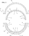
Fig. 2 is a partially exploded diagrammatic end view illustrating a measuring assembly in accordance with the present invention located in an outer casing assembly for the turbine section prior to installation of a rotor; -
Fig. 3 is a diagrammatic end view of the turbine section illustrating a measuring assembly in accordance with the present invention located in an assembled turbine section; -
Fig. 4 is a diagrammatic view illustrating a measuring assembly in accordance with the present invention on a seal segment; -
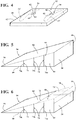
Figs. 5 and 6 are perspective views of a body member for the seal assembly illustrated inFig. 4 ; -
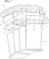
Fig. 7 is a perspective view interior view of a portion of a turbine section illustrating a measuring assembly in accordance with the present invention located to perform a tip-to-seal clearance measuring operation; -
Fig. 8 is a diagrammatic view illustrating a measuring assembly in accordance with the present invention on a seal segment and incorporating a further configuration for a seal member; and -
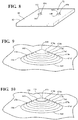
Figs. 9 and 10 are perspective views of a body member for the seal assembly illustrated inFig. 8 . - As described above with reference to the turbine engine 10 in
Fig. 1 , it is desirable to maintain a predetermined clearance betweenblade tips 26 and aninner surface 30 of an annularring seal assembly 36. Further, in accordance with aspects of the present invention, it is desirable to maintain a predetermined clearance between theblade tips 26 and theseal assembly 36 when the engine 10 is in an assembled condition. That is, it is desirable to ensure that a designed clearance between theblade tips 26 and theseal assembly 36 is maintained when the turbine section 16 of the engine 10 is in an assembled condition. - Referring to
Figs. 2 and3 , it may be seen that theouter casing structure 34 of the turbine section 16 may be formed as an uppercasing structure half 38 and a lowercasing structure half 40. Each of thecasing structure halves outer casing 32, thevane carrier 28 and theseal assembly 36. In particular, theouter casing 32 may comprise upper and lowerouter casing halves lower halves vane carrier 28. In addition, associated upper andlower halves seal assembly 36 are formed by a plurality ofseal segments 42 positioned in side-by-side relation around theinner surface 30 of thevane carrier 28. - The upper and lower
casing structure halves flanges 44 for connecting thecasing structure halves Fig. 3 ), such as by means ofbolts 48 and/or other retaining mechanisms. In accordance with an aspect of the present invention, it should be understood that although the assembledouter casing structure 34 is designed to provide a predetermined clearance between thetips 26 of theblades 20 andinner surfaces 50 of theseal segments 42 forming theseal assembly 36, attachment of thecasing structure halves bolts 48, may cause distortions to theouter casing 32 that may alter the clearance between theblade tips 26 and theinner surfaces 50 of the seal segments 42 (hereinafter referred to as tip-to-seal clearance). In addition, variations in the tip-to-seal clearance between a circumferential location at top-dead-center (TDC) and a circumferential location at bottom-dead-center (BDC) may occur as a result of rotor gravity deflection. For example, rotor gravity deflection may cause a larger tip-to-seal clearance for theblades 20 at or near TDC than for theblades 20 at or near BDC. - Referring to
Figs. 4 and 5 , in accordance with a further aspect of the invention, ameasuring assembly 52 may be provided comprising, for example, one ormore body members 54 that may be affixed to theinner surface 50 of one or more of theseal segments 42. As discussed in greater detail below, theseal assembly 52 is configured to be cut or abraded by at least one of theblade tips 26 to provide an indication of the tip-to-seal clearance after theouter casing structure 34 has been assembled. It may be noted that, for the purposes of the present invention, the terms "cut" and 'abrade" or "abraded" are considered to refer to equivalent operations and may be used interchangeably. - As seen in
Fig. 5 , thebody member 54 may comprise a wedge shaped member having afirst end 56, asecond end 58, an outwardly facingside 60 extending between the first andsecond ends side 62 extending between the first andsecond ends side 60, and a pair oflateral sides second ends side 60 extends widthwise between thelateral sides inner surface 50 of aseal segment 42, such as by means of a strong adhesive, e.g., an epoxy. It may be noted that the reference to "outwardly facing" and "inwardly facing" is relative to the orientation of thebody member 54 when it is supported on and extends radially inwardly from theseal segment 42 when mounted in the engine 10, as may be seen, for example, inFig. 3 . The inwardly facingside 62 extends widthwise between thelateral sides inner surface 50 of theseal segment 42. In particular, the inwardly facingside 62 extends progressively radially inwardly from thefirst end 56 toward thesecond end 58. In the illustrated embodiment, the inwardly facingside 62 is shown as a continuous ramp surface extending from thefirst end 56 to thesecond end 58. However, the inwardly facingside 62 may comprise other configurations including, for example, a discontinuous ramp surface, such as a ramp surface that extends radially inwardly in a stepwise manner. - The
body member 54 defines anindicia portion 68 extending radially inwardly from theinner surface 50 of theseal segment 42 to a location that may be located radially inwardly from theblade tips 26, seeFigs. 3 and7 . As seen inFig. 6 , theindicia portion 68 may include a portion orsection 70 that may be abraded or otherwise removed by theblades 20 during a rotational movement of therotor 24 andblades 20 to provide a visual indication of the tip-to-seal clearance. Thebody member 54 may function as a distance gage between theinner surface 50 of theseal segment 42 and theblade tips 26 to provide a visual indication of the tip-to-seal clearance, as indicated by a radial extension or distance from theouter surface 60 to a cut orabraded portion 72 comprising a surface formed on thebody member 54 when a portion of theinner side 62 is cut or abraded away by theblades 20 during a rotation operation performed on therotor 24 following assembly of theouter casing structure 34, as is described below. Hence, a distance indicated by theindicia portion 68 may comprise a visually observable portion of thebody member 54, e.g., on alateral side side 62, to provide an observable indication of the distance from theinner surface 50 to the cut or abradedportion 72, which may correspond to the radial location of theblade tips 26. - The
body member 54 may be formed of a material that may be readily cut or abraded by relative movement of theblade tips 26 across thebody member 54 without causing thebody member 54 to crack or otherwise deteriorate beyond the location of the cut or abradedportion 72 directly contacted by theblade tips 26. For example, thebody member 54 may preferably be formed of a polyimide material sold under the trademark VESPEL®. VESPEL® is a registered trademark of the E. I. DuPont de Nemours Company, used to describe a polyimide resin available from the E. I. DuPont de Nemours Company. In particular, abody member 54 formed of VESPEL® polyimide resin may be easily machined to accurate dimensions, and provide a durable material that permits the cut or abradedportion 72 to be accurately formed at the location of theblade tips 26 while the remainder of thebody portion 54 is substantially undeformed and otherwise unaffected, and further will burn off of theseal segment 42 upon exposure to the hot working gases passing through the turbine section 16, so as to not adversely affect operation of the engine 10. - Referring to
Figs. 5 and 6 , in accordance with a further aspect of the invention, theindicia portion 68 may include a plurality ofindicia 74, at least some of which extend radially inwardly of thetips 26 of theblades 20 to facilitate a determination of a radial distance of the cut or abradedportion 72 from theinner surface 50. In the illustrated embodiment, theindicia 74 may comprise a plurality of generally parallel line marks or grooves that may provide a visual indication of locations spaced along thebody member 54 in a direction from thefirst end 56 toward thesecond end 58. That is, theindicia 74 may provide a graduated measurement scale, where the locations of theindicia 74 correspond to predetermined radial measurement locations, i.e., radial distances, from the outwardly facingside 60 to the inwardly facingside 62. In a specific configuration of thebody member 54, the distance from the outwardly facingside 60 to the inwardly facingside 62 at thesecond end 58 may be about 4.0 mm, and theindicia 74 may be spaced at locations along one or both of the lateral sides 64, 66 corresponding to 0.5 mm increments of the radial measurement locations along the ramp surface defined by the inwardly facingside 62. For example,indicia 74a may correspond to a radial measurement location of 3.5 mm,indicia 74b may correspond to a radial measurement location of 3.0 mm, andindicia 74c may correspond to a radial measurement location of 2.5 mm. Hence, the radial distance between theinner surface 50 of theseal segment 42 and theblade tips 26 may be determined by identifying an intersection location 76 (Fig. 6 ) where the ramp surface defined by the inwardly facingside 62 intersects the cut or abradedportion 72 with reference to theparticular indicia 74 that is nearest to theintersection location 76. - The distance from the outwardly facing
side 60 to the inwardly facingside 62 at thesecond end 58 of thebody member 54 is selected such that the inwardly facingside 62 extends to a radial location within the turbine section 16 that is radially inwardly from thetips 26 of theblades 20 when therotor 24 is installed in the turbine section 16. It should be noted that the final installed height, i.e., the radial inward extension, of thebody member 54 may include a thickness of an adhesive used to affix the body member to theseal segment 42, such that the radial inward extension may be a combined height of the adhesive thickness and the distance from the outwardly facingside 60 to the inwardly facingside 62. - In order to facilitate observation of the
indicia 74 of the measuringassembly 52 located within the engine 10, where theindicia 74 are defined by grooves, the grooves may be painted, or otherwise coated, with a contrasting color relative to the color of the lateral sides 64, 66. Alternatively, the lateral sides 64, 66 may be painted, or otherwise coated, with a contrasting color to thebody member 54 prior to forming grooves defining theindicia 74, such that indicia appear with a different or contrasting color relative to the lateral sides 64, 66 upon formation of the grooves. - In a process for determining a tip-to-seal clearance measurement, as depicted in
Figs. 2 and3 , the measuringassembly 52 may be installed as a plurality of thebody members 54 attached to the annularring seal assembly 36 at a plurality of predetermined circumferential locations. Thebody members 54 are preferably attached to theseal segments 42 of thering seal assembly 36 such that thefirst end 56 of thebody member 54 is located upstream from thesecond end 58 of thebody member 54, with reference to the direction of rotation of therotor 24, positioning the inwardly facingside 62 to be initially contacted by arotating blade 20 as theblade 20 rotates toward thesecond end 58 of thebody member 54. - It should be noted that although the preferred implementation of the measuring
assembly 52 is described with reference to a plurality of thebody members 54, a form of the present invention may be performed using a single one of thebody members 54. The plurality ofbody members 54 provide measurements at locations where different tip-to-seal clearances may occur around the circumference of thering seal assembly 36. Further, pairs of thebody members 54 may be provided at the same location, i.e. on thesame seal segment 42 or onadjacent seal segments 42, to provide a redundant measurement structure in case one of thebody members 54 is damaged during installation of therotor 24 or assembly of theouter casing structure 34. - The plurality of predetermined circumferential measurement locations may be at or near top-dead-center and bottom-dead-center, and at or near each of the locations of the
horizontal joints 46. For example, a pair ofbody members 54 may be affixed to thering seal assembly 36 at each of the TDC and BDC locations, andbody members 54 may be affixed to theseal segments 42 of theupper half 36A of thering seal assembly 36 adjacent to the locations of thehorizontal joints 46 prior to mounting of therotor 24 and assembly of theupper half 36A to thelower half 36B of thering seal assembly 36. Subsequent to installation of therotor 24 and associatedblades 20 and prior to assembly of the uppercasing structure half 38 to the lowercasing structure half 40,body members 54 may be affixed to theseal segments 42 of thelower half 36B of thering seal assembly 36 adjacent to the locations of thehorizontal joints 46. The uppercasing structure half 38 may then be positioned on the lowercasing structure half 40, and the two casing structure halves 38, 40 may be attached together by thebolts 48. - To determine the tip-to-seal clearance, the
rotor 24 may be driven in rotation, such as by a hydraulic motor, or other means, temporarily coupled to therotor 24. Rotation of therotor 24 causes theblades 20 to engage and remove, i.e., by cutting or abrading, thesection 70 of theindicia portion 68 to define the surface of the cut or abradedportion 72 on thebody member 54. It may be noted that therotor 24 may be rotated at a slow rate of rotation, such as 1 rpm or less, in that the speed of rotation of therotor 24 is not critical to the cutting or abrading operation resulting from movement of theblades 20 relative to thebody members 54. - As illustrated in
Fig. 7 , a flexible inspection instrument, such as aborescope 78, may be inserted through the turbine section 16 to locate anend 80 of theborescope 78 at the location of the measuringassembly 52. Theend 80 of theborescope 78 may be provided with aCCD camera 82 to view thebody members 54 of the measuringassembly 52 remotely, i.e., at an end of theborescope 78 outside of the engine 10, to determine the location of theparticular indicia 74 corresponding to or located near theintersection 76 of the ramped inwardly facingside 62 with the cut or abradedportion 72. Alternatively, other optical structures may be provided to theborescope 78 for viewing the measuring assembly. Theborescope 78 may be inserted through the exhaust end of the turbine section 16, or theborescope 78 may be inserted through an inspection opening, such as is typically provided through turbine engine casings. Further, it should be understood that the measuringassembly 52 may be provided to any one of the stages ofrotating blades 20 within the turbine section 16, or may be provided to a plurality of the stages ofrotating blades 20 and may be inspected by causing theborescope 78 to be guided through the series ofvanes 18 andblades 20 forming the stages of the turbine section 16 until theend 80 of theborescope 78 is located at the stage containing the measuringassembly 52. - By viewing the indicia on either of the lateral sides 64, 66 of the
body members 54, i.e., as viewed by theborescope 78 in the generally axial direction, the tip-to-seal clearance may be determined at each of the predetermined circumferential measurement locations around thering seal assembly 36. Further, a tip-to-seal clearance may also be determined by an alternative measurement system, such as by use of a feeler gage, at the location on the lowerring seal half 36B adjacent to the location of the horizontal joint 46, i.e., subsequent to placement of therotor 24 within the turbine section 16, to provide a verification or comparison of the tip-to-seal clearance measurement before and after assembly of theouter casing assembly 34. - As noted above, pairs of the
body members 54 may be provided at each of the circumferential measurement locations in case one of thebody members 54 is damaged during installation of therotor 24 or assembly of theouter casing assembly 34. For example, as illustrated by phantom lines 26' illustrating the shadow ofblade tips 26 on theseal segment 42 inFig. 4 and corresponding, for example, to theseal segment 42 located at the BDC of thering seal assembly 36, installation of therotor 24 into the lowercasing structure half 40 may result in oneblade tip 26 engaging and possibly damaging one of thebody members 54, while anadjacent body member 54 may not be engaged with ablade tip 26. Hence, by appropriate circumferential spacing of thebody members 54 at each of the predetermined circumferential measurement locations, it may be possible to substantially ensure that at least one of the pairs ofbody members 54 is undamaged prior to rotation of therotor 24 during the measurement operation. - Referring to
Figs. 8 and 9 , a further configuration for a body member of the measuringassembly 52 is illustrated by abody member 154, where the measuringassembly 52 may comprise one or more of thebody members 154 affixed to theinner surface 50 of one or more of theseal segments 42. Thebody member 154 may be formed of a VESPEL® polyimide resin, and may comprise a generally conical shaped member, e.g., a cone of revolution, having afirst end 156, defining a base of the cone, located at an outwardly facingside 160 for rigidly affixing to theinner surface 50 of theseal segment 42, and asecond end 158 located at the vertex of the cone defined by thebody member 154. It should be understood the generally conical shape of thebody member 154 may comprise a frustum of a cone, i.e., with a portion of the cone cut off at the apex, in which case thesecond end 158 would be located at the outer end of the frustum of the cone. - The outer surface of the
body member 154 extending from thefirst end 156 to thesecond end 158 comprises an inwardly facingside 162 of thebody member 154. The inwardly facingside 162 defines a ramp surface extending at a predetermined angle from thefirst end 156 toward thesecond end 158 around the circumference of thebody member 154. At least a portion of thebody member 154 is located radially inwardly from thetips 26 of theblades 20 at thesecond end 158 of thebody member 154. - The
body member 154 may provide a tip-to-seal clearance measurement in a manner substantially similar to that described above for theseal member 54. In particular, rotation of therotor 24 andblades 20 may cause an indicia portion 168 comprising a portion orsection 170 of thebody member 154 to be cut or abraded, as is illustrated inFig. 10 . A cut or abradedportion 172 comprising a surface formed on thebody member 154 is defined when a portion of the inwardly facingside 162 is cut or abraded away by theblades 20 during a rotation operation performed on therotor 24, as described above. The indicia portion 168 may further include a plurality ofindicia 174 comprising a plurality of generally parallel line marks orgrooves 174a-f formed on the inwardly facingsurface 162 and encircling thebody member 154 to define a graduated measurement scale. The indicia lines orgrooves 174a-f are spaced at predetermined intervals in the direction from thefirst end 156 toward thesecond end 158, eachindicia 174 corresponding to and providing an indication of a different radial distance radially inwardly from thefirst end 156. During a tip-to-seal measurement operation, the indicia portion section 168 may be cut or abraded by passage of ablade 20, removing anyindicia 174 that are located radially inwardly from thetip 26 of theblade 20. Hence, the remaining portion of thebody member 154 may be visually observed to determine the remainingindicia 174, providing a visual indication for measurement of the tip-to-seal clearance, such as by use of a borescope 78 (Fig. 7 ). - It should be noted that the
body member 154 provides a configuration wherein theindicia 174 encircling thebody member 154 may be observed from any direction relative to thebody member 154. Hence, thebody member 154 may facilitate observation of theindicia 174 without necessitating locating of theborescope 78 to a particular angular position relative to thebody member 154. - Further, it should be understood that other configurations of the body members for the measuring
assembly 52 may be provided. For example, the body member may be configured as a pyramid that may be positioned on the seal segment in a manner which permits a radially extending portion of the body member to extend radially inwardly from thetips 26 of theblades 20 before rotation of theblades 20 to cut or abrade the body member. - Also, although a particular number of
indicia body members
Claims (6)
- A turbine engine comprising an outer casing (32) supporting an annular vane carrier (28), an annular stationary seal structure (36) supported on the vane carrier, and a rotor (24) rotatable about an axis and having a plurality of blades (20), each blade having a tip (26) proximate to an inner surface (50) of the seal structure, said turbine engine further comprising a measuring assembly (52) comprising:a body member (54, 154) having an outwardly facing side (60, 160) attached to said inner surface of said seal structure; andsaid body member having an inwardly facing side (62, 162), opposite said outwardly facing side, said body member extending radially inwardly from said inner surface of said seal structure to a location radially inwardly from said tips of said blades, characterised in that said body member includes a plurality of indicia (74, 174) for providing an incremental visual indication for determining the clearance between said tips of said blades and said inner surface of said seal structure, and in that said inwardly facing side (62, 162) extends at an angle relative to said inner surface (50), and in that said body member is abradable, the rotation of said rotor abrading a portion (70, 170) of the body member, the abraded portion being indicative of said clearance, the abraded portion having a measurement location relative to said indicia, said measurement location corresponding to a distance of said abraded portion from said inner surface of said seal structure.
- The turbine engine according to claim 1, wherein said body member (54, 154) includes a first end (56, 156) and a second end (58, 158), and said plurality of indicia (74, 174) are spaced along said body member from said first end to said second end and correspond to a plurality of measurement locations on said inwardly facing side (62, 162).
- The turbine engine according to claim 2, wherein said body member (54) comprises a wedge shape having a ramp surface defining said inwardly facing side (62) and including a lateral surface (64) extending radially between said ramp surface and said outwardly facing side (60), and said indicia (74) comprise generally parallel line marks located on said lateral surface.
- The turbine engine according to claim 2, wherein said body member (154) comprises a conical shape having a base defining said outwardly facing side (160), and said indicia (174) comprise generally parallel line marks defined on said inwardly facing side (162) extending around said body member.
- A method of determining a clearance between an inner surface (50) of an annular seal assembly (36) and tips (26) of blades (20) mounted to a rotor (24) in a gas turbine engine, said annular seal assembly supported within an outer casing structure (34) of the turbine engine and said outer casing structure comprising a lower casing structure half (40) and an upper casing structure half (38), the method comprising:providing a measuring assembly (52) on said inner surface of said seal assembly, said measuring assembly including a body member (54, 154) extending radially inwardly from said inner surface of said seal assembly to a location radially inwardly from said tips of said blades, wherein said body member has an outwardly facing side (60, 160) attached to said inner surface of said seal assembly, and an inwardly facing side (62, 162) opposite said outwardly facing side, said inwardly facing side (62, 162) extending at an angle relative to said inner surface (50);rotating said rotor at a rate to abrade a portion (70, 170) of said body member of said measuring assembly, said abraded portion being indicative of said clearance; andinspecting said abraded portion from a location exterior of said outer casing structure to obtain an indication of said clearance between said inner surface of said annular seal assembly and said tips of said blades,wherein said body member includes a plurality of indicia (74, 174) for providing an incremental visual indication for determining said clearance between said inner surface of said annular seal assembly and said tips of said blades,wherein said indicia define a graduated scale, and said inspecting said abraded portion comprises identifying a measurement location of said abraded portion relative to said graduated scale, said measurement location corresponding to a distance of said abraded portion from said inner surface of said seal assembly.
- The method according to claim 5, wherein said upper casing structure half (38) is engaged on said lower casing structure half (40) during said step of inspecting, and said step of inspecting comprises inserting a borescope (78) through said outer casing structure (34) to view said abraded portion (70, 170).
Applications Claiming Priority (2)
| Application Number | Priority Date | Filing Date | Title |
|---|---|---|---|
| US13/027,354 US8684669B2 (en) | 2011-02-15 | 2011-02-15 | Turbine tip clearance measurement |
| PCT/US2012/024397 WO2012112366A1 (en) | 2011-02-15 | 2012-02-09 | Turbine tip clearance measurement |
Publications (2)
| Publication Number | Publication Date |
|---|---|
| EP2676002A1 EP2676002A1 (en) | 2013-12-25 |
| EP2676002B1 true EP2676002B1 (en) | 2018-03-28 |
Family
ID=45771901
Family Applications (1)
| Application Number | Title | Priority Date | Filing Date |
|---|---|---|---|
| EP12706367.5A Not-in-force EP2676002B1 (en) | 2011-02-15 | 2012-02-09 | Turbine tip clearance measurement |
Country Status (3)
| Country | Link |
|---|---|
| US (1) | US8684669B2 (en) |
| EP (1) | EP2676002B1 (en) |
| WO (1) | WO2012112366A1 (en) |
Families Citing this family (28)
| Publication number | Priority date | Publication date | Assignee | Title |
|---|---|---|---|---|
| US9322280B2 (en) | 2011-08-12 | 2016-04-26 | United Technologies Corporation | Method of measuring turbine blade tip erosion |
| EP2730370B1 (en) * | 2012-11-13 | 2015-10-14 | Siemens Aktiengesellschaft | Method to adjust a predetermined radial tip clearance of a turbomachine blade |
| US9833869B2 (en) * | 2013-02-11 | 2017-12-05 | United Technologies Corporation | Blade outer air seal surface |
| US10612407B2 (en) | 2013-02-28 | 2020-04-07 | United Technologies Corporation | Contoured blade outer air seal for a gas turbine engine |
| FR3006013B1 (en) * | 2013-05-21 | 2017-10-13 | Turbomeca | TURBOMACHINE COMPRISING A WEAR OF THE CARTER |
| US9513117B2 (en) | 2013-10-02 | 2016-12-06 | Siemens Energy, Inc. | Situ blade mounted tip gap measurement for turbines |
| US9068906B2 (en) * | 2013-10-02 | 2015-06-30 | Siemens Energy, Inc. | Turbine blade-mounted sensor fixture for tip gap measurement |
| US9957834B2 (en) * | 2013-10-03 | 2018-05-01 | United Technologies Corporation | Rotor blade tip clearance |
| GB201415201D0 (en) * | 2014-08-28 | 2014-10-15 | Rolls Royce Plc | A wear monitor for a gas turbine engine fan |
| US10267173B2 (en) * | 2014-10-22 | 2019-04-23 | Rolls-Royce Corporation | Gas turbine engine with seal inspection features |
| CN107075965B (en) * | 2014-10-23 | 2020-04-14 | 西门子能源公司 | Gas Turbine Engine with Turbine Blade Tip Clearance Control System |
| DE102015224454A1 (en) * | 2015-12-07 | 2017-06-08 | Rolls-Royce Deutschland Ltd & Co Kg | Tarpaulin, process for producing a squat lining and aircraft engine with tarnish |
| EP3179055A1 (en) * | 2015-12-09 | 2017-06-14 | Ansaldo Energia IP UK Limited | A gas turbine part comprising a lifetime indicator |
| US10619998B2 (en) | 2016-05-26 | 2020-04-14 | Rolls-Royce Corporation | Method of measuring clearance between rotating and static components |
| US10428674B2 (en) | 2017-01-31 | 2019-10-01 | Rolls-Royce North American Technologies Inc. | Gas turbine engine features for tip clearance inspection |
| US10612413B2 (en) | 2017-03-06 | 2020-04-07 | United Technologies Corporation | Wear indicator for determining wear on a component of a gas turbine engine |
| US10222200B2 (en) | 2017-05-12 | 2019-03-05 | Siemens Energy, Inc. | Contactless, blade-tip clearance measurement for turbines |
| CN107121048B (en) * | 2017-05-23 | 2023-02-28 | 深圳怡化电脑股份有限公司 | Reversing blade positioning and checking jig |
| KR101914870B1 (en) * | 2017-06-28 | 2018-12-28 | 두산중공업 주식회사 | Method of disassembling and assembling a gas turbine and a gas turbine assembled thereby |
| KR101965493B1 (en) * | 2017-06-28 | 2019-04-03 | 두산중공업 주식회사 | Method of disassembling and assembling a gas turbine and a gas turbine assembled thereby |
| US10760445B2 (en) | 2017-08-03 | 2020-09-01 | Raytheon Technologies Corporation | Electrical resistance wear indicator |
| US10731506B2 (en) * | 2017-12-19 | 2020-08-04 | Raytheon Technologies Corporation | Capacitance based wear indicator |
| CN109406153B (en) * | 2018-12-14 | 2020-09-18 | 中国航发沈阳发动机研究所 | Aeroengine strutting arrangement, test device |
| FR3091548B1 (en) * | 2019-01-09 | 2022-12-09 | Safran Aircraft Engines | Abradable turbomachine element provided with visual wear indicators |
| CN110159580A (en) * | 2019-05-22 | 2019-08-23 | 沈阳透平机械股份有限公司 | The dynamic clearance detection device and detection method of centrifugal compressor stator elements and impeller |
| CN110440674B (en) * | 2019-08-29 | 2021-07-13 | 中国航发航空科技股份有限公司 | A detection device for the surface profile of the guide vane channel surface |
| EP4170132A1 (en) * | 2021-10-20 | 2023-04-26 | Siemens Energy Global GmbH & Co. KG | Blade for turbomachine and method for producing a blade, the blade comprising a tip with an abradable coating |
| CN114382557B (en) * | 2022-01-11 | 2022-10-28 | 西安交通大学 | Test structure for simulating turbine dynamic and static disc cavity leakage flow prerotation |
Citations (2)
| Publication number | Priority date | Publication date | Assignee | Title |
|---|---|---|---|---|
| GB2297162A (en) * | 1995-01-21 | 1996-07-24 | Abb Management Ag | Method and device for measuring the blade clearance of thermal turbomachines |
| EP1113146A2 (en) * | 1999-12-27 | 2001-07-04 | General Electric Company | Rotatory machine having a seal assembly |
Family Cites Families (24)
| Publication number | Priority date | Publication date | Assignee | Title |
|---|---|---|---|---|
| US3936217A (en) * | 1975-01-31 | 1976-02-03 | Westinghouse Electric Corporation | Inspection port for turbines |
| FR2339741A1 (en) | 1976-01-30 | 1977-08-26 | Snecma | ABRADABLE STATOR GASKET FOR AXIAL TURBOMACHINE AND ITS EXECUTION PROCESS |
| GB2090333B (en) | 1980-12-18 | 1984-04-26 | Rolls Royce | Gas turbine engine shroud/blade tip control |
| US4395827A (en) | 1981-12-21 | 1983-08-02 | General Electric Company | Clearance measuring method and apparatus |
| US4764089A (en) | 1986-08-07 | 1988-08-16 | Allied-Signal Inc. | Abradable strain-tolerant ceramic coated turbine shroud |
| US4876505A (en) | 1988-05-27 | 1989-10-24 | Westinghouse Electric Corp. | Apparatus and method for monitoring steam turbine shroud clearance |
| US6148518A (en) * | 1998-12-22 | 2000-11-21 | United Technologies Corporation | Method of assembling a rotary machine |
| US6224332B1 (en) | 1999-05-14 | 2001-05-01 | General Electric Co. | Apparatus and methods for installing, removing and adjusting an inner turbine shell section relative to an outer turbine shell section |
| DE19945581B4 (en) | 1999-09-23 | 2014-04-03 | Alstom Technology Ltd. | turbomachinery |
| FR2811422B1 (en) | 2000-07-06 | 2002-08-30 | Snecma Moteurs | MULTI-DEPTH ABRASION GAME MEASUREMENT SENSOR |
| US6325596B1 (en) | 2000-07-21 | 2001-12-04 | General Electric Company | Turbine diaphragm support system |
| US6935836B2 (en) | 2002-06-05 | 2005-08-30 | Allison Advanced Development Company | Compressor casing with passive tip clearance control and endwall ovalization control |
| US7572524B2 (en) | 2002-09-23 | 2009-08-11 | Siemens Energy, Inc. | Method of instrumenting a component |
| US6838157B2 (en) | 2002-09-23 | 2005-01-04 | Siemens Westinghouse Power Corporation | Method and apparatus for instrumenting a gas turbine component having a barrier coating |
| US7618712B2 (en) | 2002-09-23 | 2009-11-17 | Siemens Energy, Inc. | Apparatus and method of detecting wear in an abradable coating system |
| US7270890B2 (en) * | 2002-09-23 | 2007-09-18 | Siemens Power Generation, Inc. | Wear monitoring system with embedded conductors |
| US7582359B2 (en) | 2002-09-23 | 2009-09-01 | Siemens Energy, Inc. | Apparatus and method of monitoring operating parameters of a gas turbine |
| US6848193B1 (en) * | 2003-11-26 | 2005-02-01 | General Electric Company | Methods and systems for machine monitoring system calibration |
| US7708518B2 (en) | 2005-06-23 | 2010-05-04 | Siemens Energy, Inc. | Turbine blade tip clearance control |
| US7511516B2 (en) | 2006-06-13 | 2009-03-31 | General Electric Company | Methods and systems for monitoring the displacement of turbine blades |
| US7726936B2 (en) | 2006-07-25 | 2010-06-01 | Siemens Energy, Inc. | Turbine engine ring seal |
| US8046915B2 (en) | 2007-12-12 | 2011-11-01 | General Electric Company | Methods for making composite containment casings |
| GB2460248B (en) | 2008-05-21 | 2011-01-12 | Rolls Royce Plc | Clearance determination device |
| US8177494B2 (en) | 2009-03-15 | 2012-05-15 | United Technologies Corporation | Buried casing treatment strip for a gas turbine engine |
-
2011
- 2011-02-15 US US13/027,354 patent/US8684669B2/en not_active Expired - Fee Related
-
2012
- 2012-02-09 WO PCT/US2012/024397 patent/WO2012112366A1/en not_active Ceased
- 2012-02-09 EP EP12706367.5A patent/EP2676002B1/en not_active Not-in-force
Patent Citations (2)
| Publication number | Priority date | Publication date | Assignee | Title |
|---|---|---|---|---|
| GB2297162A (en) * | 1995-01-21 | 1996-07-24 | Abb Management Ag | Method and device for measuring the blade clearance of thermal turbomachines |
| EP1113146A2 (en) * | 1999-12-27 | 2001-07-04 | General Electric Company | Rotatory machine having a seal assembly |
Also Published As
| Publication number | Publication date |
|---|---|
| EP2676002A1 (en) | 2013-12-25 |
| US20120207586A1 (en) | 2012-08-16 |
| WO2012112366A1 (en) | 2012-08-23 |
| US8684669B2 (en) | 2014-04-01 |
Similar Documents
| Publication | Publication Date | Title |
|---|---|---|
| US8684669B2 (en) | Turbine tip clearance measurement | |
| EP3211366B1 (en) | Detectable datum markers for gas turbine engine components for measuring distortion | |
| EP2870346B1 (en) | Advanced tip-timing measurement blade mode identification | |
| US8695445B2 (en) | Wear-indicating system for use with turbine engines and methods of inspecting same | |
| US8102539B2 (en) | Method for measuring a gap between a multibladed rotatable member and a surrounding housing | |
| EP2990660B1 (en) | A wear monitor for a gas turbine engine | |
| EP2375004A2 (en) | Methods, systems and apparatus relating to tip clearance calculations in turbine engines | |
| US20090165540A1 (en) | Method for measuring blade tip clearance | |
| JP5638707B2 (en) | Method for determining the diameter of a rotor with rotor blades in a turbomachine | |
| US20100043576A1 (en) | Apparatus for Measuring Blade Tip Clearance | |
| EP3176377A1 (en) | Wear indication system and corresponding turbine engine component | |
| JP2017096272A (en) | System and method for monitoring components | |
| EP3647534A1 (en) | Turbine component performance inspection sleeve and method of inspecting engine component | |
| US10731506B2 (en) | Capacitance based wear indicator | |
| EP3012414B1 (en) | Gas turbine engine with seal inspection features | |
| US10428674B2 (en) | Gas turbine engine features for tip clearance inspection | |
| WO2012091821A1 (en) | Apparatus and method for measuring runout | |
| US8297136B2 (en) | Instrumentation arrangement | |
| US20250198735A1 (en) | Method for locating a mark on a turbomachine casing | |
| EP2574734B1 (en) | Systems and methods for mode shape identification | |
| EP4726175A1 (en) | Tool and method for determining impeller leading edge conformity |
Legal Events
| Date | Code | Title | Description |
|---|---|---|---|
| PUAI | Public reference made under article 153(3) epc to a published international application that has entered the european phase |
Free format text: ORIGINAL CODE: 0009012 |
|
| 17P | Request for examination filed |
Effective date: 20130812 |
|
| AK | Designated contracting states |
Kind code of ref document: A1 Designated state(s): AL AT BE BG CH CY CZ DE DK EE ES FI FR GB GR HR HU IE IS IT LI LT LU LV MC MK MT NL NO PL PT RO RS SE SI SK SM TR |
|
| DAX | Request for extension of the european patent (deleted) | ||
| STAA | Information on the status of an ep patent application or granted ep patent |
Free format text: STATUS: EXAMINATION IS IN PROGRESS |
|
| 17Q | First examination report despatched |
Effective date: 20170328 |
|
| REG | Reference to a national code |
Ref country code: DE Ref legal event code: R079 Ref document number: 602012044447 Country of ref document: DE Free format text: PREVIOUS MAIN CLASS: F01D0011120000 Ipc: G01B0005140000 |
|
| GRAP | Despatch of communication of intention to grant a patent |
Free format text: ORIGINAL CODE: EPIDOSNIGR1 |
|
| STAA | Information on the status of an ep patent application or granted ep patent |
Free format text: STATUS: GRANT OF PATENT IS INTENDED |
|
| RIC1 | Information provided on ipc code assigned before grant |
Ipc: F01D 11/12 20060101ALI20171010BHEP Ipc: G01B 5/14 20060101AFI20171010BHEP Ipc: F01D 17/02 20060101ALI20171010BHEP |
|
| INTG | Intention to grant announced |
Effective date: 20171030 |
|
| GRAS | Grant fee paid |
Free format text: ORIGINAL CODE: EPIDOSNIGR3 |
|
| GRAA | (expected) grant |
Free format text: ORIGINAL CODE: 0009210 |
|
| STAA | Information on the status of an ep patent application or granted ep patent |
Free format text: STATUS: THE PATENT HAS BEEN GRANTED |
|
| AK | Designated contracting states |
Kind code of ref document: B1 Designated state(s): AL AT BE BG CH CY CZ DE DK EE ES FI FR GB GR HR HU IE IS IT LI LT LU LV MC MK MT NL NO PL PT RO RS SE SI SK SM TR |
|
| REG | Reference to a national code |
Ref country code: GB Ref legal event code: FG4D |
|
| REG | Reference to a national code |
Ref country code: CH Ref legal event code: EP |
|
| REG | Reference to a national code |
Ref country code: AT Ref legal event code: REF Ref document number: 983836 Country of ref document: AT Kind code of ref document: T Effective date: 20180415 |
|
| REG | Reference to a national code |
Ref country code: IE Ref legal event code: FG4D |
|
| REG | Reference to a national code |
Ref country code: DE Ref legal event code: R096 Ref document number: 602012044447 Country of ref document: DE |
|
| PG25 | Lapsed in a contracting state [announced via postgrant information from national office to epo] |
Ref country code: NO Free format text: LAPSE BECAUSE OF FAILURE TO SUBMIT A TRANSLATION OF THE DESCRIPTION OR TO PAY THE FEE WITHIN THE PRESCRIBED TIME-LIMIT Effective date: 20180628 Ref country code: HR Free format text: LAPSE BECAUSE OF FAILURE TO SUBMIT A TRANSLATION OF THE DESCRIPTION OR TO PAY THE FEE WITHIN THE PRESCRIBED TIME-LIMIT Effective date: 20180328 Ref country code: LT Free format text: LAPSE BECAUSE OF FAILURE TO SUBMIT A TRANSLATION OF THE DESCRIPTION OR TO PAY THE FEE WITHIN THE PRESCRIBED TIME-LIMIT Effective date: 20180328 Ref country code: FI Free format text: LAPSE BECAUSE OF FAILURE TO SUBMIT A TRANSLATION OF THE DESCRIPTION OR TO PAY THE FEE WITHIN THE PRESCRIBED TIME-LIMIT Effective date: 20180328 |
|
| REG | Reference to a national code |
Ref country code: NL Ref legal event code: MP Effective date: 20180328 |
|
| REG | Reference to a national code |
Ref country code: LT Ref legal event code: MG4D |
|
| PG25 | Lapsed in a contracting state [announced via postgrant information from national office to epo] |
Ref country code: RS Free format text: LAPSE BECAUSE OF FAILURE TO SUBMIT A TRANSLATION OF THE DESCRIPTION OR TO PAY THE FEE WITHIN THE PRESCRIBED TIME-LIMIT Effective date: 20180328 Ref country code: LV Free format text: LAPSE BECAUSE OF FAILURE TO SUBMIT A TRANSLATION OF THE DESCRIPTION OR TO PAY THE FEE WITHIN THE PRESCRIBED TIME-LIMIT Effective date: 20180328 Ref country code: GR Free format text: LAPSE BECAUSE OF FAILURE TO SUBMIT A TRANSLATION OF THE DESCRIPTION OR TO PAY THE FEE WITHIN THE PRESCRIBED TIME-LIMIT Effective date: 20180629 Ref country code: BG Free format text: LAPSE BECAUSE OF FAILURE TO SUBMIT A TRANSLATION OF THE DESCRIPTION OR TO PAY THE FEE WITHIN THE PRESCRIBED TIME-LIMIT Effective date: 20180628 Ref country code: SE Free format text: LAPSE BECAUSE OF FAILURE TO SUBMIT A TRANSLATION OF THE DESCRIPTION OR TO PAY THE FEE WITHIN THE PRESCRIBED TIME-LIMIT Effective date: 20180328 |
|
| PG25 | Lapsed in a contracting state [announced via postgrant information from national office to epo] |
Ref country code: AL Free format text: LAPSE BECAUSE OF FAILURE TO SUBMIT A TRANSLATION OF THE DESCRIPTION OR TO PAY THE FEE WITHIN THE PRESCRIBED TIME-LIMIT Effective date: 20180328 Ref country code: NL Free format text: LAPSE BECAUSE OF FAILURE TO SUBMIT A TRANSLATION OF THE DESCRIPTION OR TO PAY THE FEE WITHIN THE PRESCRIBED TIME-LIMIT Effective date: 20180328 Ref country code: ES Free format text: LAPSE BECAUSE OF FAILURE TO SUBMIT A TRANSLATION OF THE DESCRIPTION OR TO PAY THE FEE WITHIN THE PRESCRIBED TIME-LIMIT Effective date: 20180328 Ref country code: PL Free format text: LAPSE BECAUSE OF FAILURE TO SUBMIT A TRANSLATION OF THE DESCRIPTION OR TO PAY THE FEE WITHIN THE PRESCRIBED TIME-LIMIT Effective date: 20180328 Ref country code: RO Free format text: LAPSE BECAUSE OF FAILURE TO SUBMIT A TRANSLATION OF THE DESCRIPTION OR TO PAY THE FEE WITHIN THE PRESCRIBED TIME-LIMIT Effective date: 20180328 Ref country code: EE Free format text: LAPSE BECAUSE OF FAILURE TO SUBMIT A TRANSLATION OF THE DESCRIPTION OR TO PAY THE FEE WITHIN THE PRESCRIBED TIME-LIMIT Effective date: 20180328 |
|
| PG25 | Lapsed in a contracting state [announced via postgrant information from national office to epo] |
Ref country code: SK Free format text: LAPSE BECAUSE OF FAILURE TO SUBMIT A TRANSLATION OF THE DESCRIPTION OR TO PAY THE FEE WITHIN THE PRESCRIBED TIME-LIMIT Effective date: 20180328 Ref country code: CZ Free format text: LAPSE BECAUSE OF FAILURE TO SUBMIT A TRANSLATION OF THE DESCRIPTION OR TO PAY THE FEE WITHIN THE PRESCRIBED TIME-LIMIT Effective date: 20180328 Ref country code: SM Free format text: LAPSE BECAUSE OF FAILURE TO SUBMIT A TRANSLATION OF THE DESCRIPTION OR TO PAY THE FEE WITHIN THE PRESCRIBED TIME-LIMIT Effective date: 20180328 |
|
| REG | Reference to a national code |
Ref country code: AT Ref legal event code: MK05 Ref document number: 983836 Country of ref document: AT Kind code of ref document: T Effective date: 20180328 |
|
| PG25 | Lapsed in a contracting state [announced via postgrant information from national office to epo] |
Ref country code: PT Free format text: LAPSE BECAUSE OF FAILURE TO SUBMIT A TRANSLATION OF THE DESCRIPTION OR TO PAY THE FEE WITHIN THE PRESCRIBED TIME-LIMIT Effective date: 20180730 |
|
| REG | Reference to a national code |
Ref country code: DE Ref legal event code: R097 Ref document number: 602012044447 Country of ref document: DE |
|
| PG25 | Lapsed in a contracting state [announced via postgrant information from national office to epo] |
Ref country code: DK Free format text: LAPSE BECAUSE OF FAILURE TO SUBMIT A TRANSLATION OF THE DESCRIPTION OR TO PAY THE FEE WITHIN THE PRESCRIBED TIME-LIMIT Effective date: 20180328 Ref country code: AT Free format text: LAPSE BECAUSE OF FAILURE TO SUBMIT A TRANSLATION OF THE DESCRIPTION OR TO PAY THE FEE WITHIN THE PRESCRIBED TIME-LIMIT Effective date: 20180328 |
|
| PLBE | No opposition filed within time limit |
Free format text: ORIGINAL CODE: 0009261 |
|
| STAA | Information on the status of an ep patent application or granted ep patent |
Free format text: STATUS: NO OPPOSITION FILED WITHIN TIME LIMIT |
|
| 26N | No opposition filed |
Effective date: 20190103 |
|
| PG25 | Lapsed in a contracting state [announced via postgrant information from national office to epo] |
Ref country code: SI Free format text: LAPSE BECAUSE OF FAILURE TO SUBMIT A TRANSLATION OF THE DESCRIPTION OR TO PAY THE FEE WITHIN THE PRESCRIBED TIME-LIMIT Effective date: 20180328 |
|
| REG | Reference to a national code |
Ref country code: CH Ref legal event code: PL |
|
| PG25 | Lapsed in a contracting state [announced via postgrant information from national office to epo] |
Ref country code: MC Free format text: LAPSE BECAUSE OF FAILURE TO SUBMIT A TRANSLATION OF THE DESCRIPTION OR TO PAY THE FEE WITHIN THE PRESCRIBED TIME-LIMIT Effective date: 20180328 Ref country code: LU Free format text: LAPSE BECAUSE OF NON-PAYMENT OF DUE FEES Effective date: 20190209 |
|
| REG | Reference to a national code |
Ref country code: BE Ref legal event code: MM Effective date: 20190228 |
|
| REG | Reference to a national code |
Ref country code: IE Ref legal event code: MM4A |
|
| PG25 | Lapsed in a contracting state [announced via postgrant information from national office to epo] |
Ref country code: CH Free format text: LAPSE BECAUSE OF NON-PAYMENT OF DUE FEES Effective date: 20190228 Ref country code: LI Free format text: LAPSE BECAUSE OF NON-PAYMENT OF DUE FEES Effective date: 20190228 |
|
| PG25 | Lapsed in a contracting state [announced via postgrant information from national office to epo] |
Ref country code: IE Free format text: LAPSE BECAUSE OF NON-PAYMENT OF DUE FEES Effective date: 20190209 |
|
| PG25 | Lapsed in a contracting state [announced via postgrant information from national office to epo] |
Ref country code: BE Free format text: LAPSE BECAUSE OF NON-PAYMENT OF DUE FEES Effective date: 20190228 |
|
| PG25 | Lapsed in a contracting state [announced via postgrant information from national office to epo] |
Ref country code: TR Free format text: LAPSE BECAUSE OF FAILURE TO SUBMIT A TRANSLATION OF THE DESCRIPTION OR TO PAY THE FEE WITHIN THE PRESCRIBED TIME-LIMIT Effective date: 20180328 |
|
| PG25 | Lapsed in a contracting state [announced via postgrant information from national office to epo] |
Ref country code: MT Free format text: LAPSE BECAUSE OF NON-PAYMENT OF DUE FEES Effective date: 20190209 |
|
| PG25 | Lapsed in a contracting state [announced via postgrant information from national office to epo] |
Ref country code: CY Free format text: LAPSE BECAUSE OF FAILURE TO SUBMIT A TRANSLATION OF THE DESCRIPTION OR TO PAY THE FEE WITHIN THE PRESCRIBED TIME-LIMIT Effective date: 20180328 |
|
| PG25 | Lapsed in a contracting state [announced via postgrant information from national office to epo] |
Ref country code: IS Free format text: LAPSE BECAUSE OF FAILURE TO SUBMIT A TRANSLATION OF THE DESCRIPTION OR TO PAY THE FEE WITHIN THE PRESCRIBED TIME-LIMIT Effective date: 20180728 |
|
| PG25 | Lapsed in a contracting state [announced via postgrant information from national office to epo] |
Ref country code: HU Free format text: LAPSE BECAUSE OF FAILURE TO SUBMIT A TRANSLATION OF THE DESCRIPTION OR TO PAY THE FEE WITHIN THE PRESCRIBED TIME-LIMIT; INVALID AB INITIO Effective date: 20120209 |
|
| PGFP | Annual fee paid to national office [announced via postgrant information from national office to epo] |
Ref country code: DE Payment date: 20210419 Year of fee payment: 10 |
|
| PGFP | Annual fee paid to national office [announced via postgrant information from national office to epo] |
Ref country code: GB Payment date: 20220321 Year of fee payment: 11 |
|
| PGFP | Annual fee paid to national office [announced via postgrant information from national office to epo] |
Ref country code: IT Payment date: 20220221 Year of fee payment: 11 Ref country code: FR Payment date: 20220223 Year of fee payment: 11 |
|
| PG25 | Lapsed in a contracting state [announced via postgrant information from national office to epo] |
Ref country code: MK Free format text: LAPSE BECAUSE OF FAILURE TO SUBMIT A TRANSLATION OF THE DESCRIPTION OR TO PAY THE FEE WITHIN THE PRESCRIBED TIME-LIMIT Effective date: 20180328 |
|
| REG | Reference to a national code |
Ref country code: DE Ref legal event code: R119 Ref document number: 602012044447 Country of ref document: DE |
|
| PG25 | Lapsed in a contracting state [announced via postgrant information from national office to epo] |
Ref country code: DE Free format text: LAPSE BECAUSE OF NON-PAYMENT OF DUE FEES Effective date: 20220901 |
|
| GBPC | Gb: european patent ceased through non-payment of renewal fee |
Effective date: 20230209 |
|
| PG25 | Lapsed in a contracting state [announced via postgrant information from national office to epo] |
Ref country code: GB Free format text: LAPSE BECAUSE OF NON-PAYMENT OF DUE FEES Effective date: 20230209 |
|
| PG25 | Lapsed in a contracting state [announced via postgrant information from national office to epo] |
Ref country code: IT Free format text: LAPSE BECAUSE OF NON-PAYMENT OF DUE FEES Effective date: 20230209 Ref country code: GB Free format text: LAPSE BECAUSE OF NON-PAYMENT OF DUE FEES Effective date: 20230209 Ref country code: FR Free format text: LAPSE BECAUSE OF NON-PAYMENT OF DUE FEES Effective date: 20230228 |