EP2675960B1 - Split gusset connection - Google Patents
Split gusset connection Download PDFInfo
- Publication number
- EP2675960B1 EP2675960B1 EP12746785.0A EP12746785A EP2675960B1 EP 2675960 B1 EP2675960 B1 EP 2675960B1 EP 12746785 A EP12746785 A EP 12746785A EP 2675960 B1 EP2675960 B1 EP 2675960B1
- Authority
- EP
- European Patent Office
- Prior art keywords
- gusset
- column
- brace
- plate
- joint
- Prior art date
- Legal status (The legal status is an assumption and is not a legal conclusion. Google has not performed a legal analysis and makes no representation as to the accuracy of the status listed.)
- Active
Links
Images


Classifications
-
- E—FIXED CONSTRUCTIONS
- E04—BUILDING
- E04B—GENERAL BUILDING CONSTRUCTIONS; WALLS, e.g. PARTITIONS; ROOFS; FLOORS; CEILINGS; INSULATION OR OTHER PROTECTION OF BUILDINGS
- E04B1/00—Constructions in general; Structures which are not restricted either to walls, e.g. partitions, or floors or ceilings or roofs
- E04B1/18—Structures comprising elongated load-supporting parts, e.g. columns, girders, skeletons
- E04B1/24—Structures comprising elongated load-supporting parts, e.g. columns, girders, skeletons the supporting parts consisting of metal
- E04B1/2403—Connection details of the elongated load-supporting parts
-
- E—FIXED CONSTRUCTIONS
- E04—BUILDING
- E04H—BUILDINGS OR LIKE STRUCTURES FOR PARTICULAR PURPOSES; SWIMMING OR SPLASH BATHS OR POOLS; MASTS; FENCING; TENTS OR CANOPIES, IN GENERAL
- E04H9/00—Buildings, groups of buildings or shelters adapted to withstand or provide protection against abnormal external influences, e.g. war-like action, earthquake or extreme climate
- E04H9/02—Buildings, groups of buildings or shelters adapted to withstand or provide protection against abnormal external influences, e.g. war-like action, earthquake or extreme climate withstanding earthquake or sinking of ground
- E04H9/021—Bearing, supporting or connecting constructions specially adapted for such buildings
- E04H9/0237—Structural braces with damping devices
-
- E—FIXED CONSTRUCTIONS
- E04—BUILDING
- E04B—GENERAL BUILDING CONSTRUCTIONS; WALLS, e.g. PARTITIONS; ROOFS; FLOORS; CEILINGS; INSULATION OR OTHER PROTECTION OF BUILDINGS
- E04B1/00—Constructions in general; Structures which are not restricted either to walls, e.g. partitions, or floors or ceilings or roofs
- E04B1/18—Structures comprising elongated load-supporting parts, e.g. columns, girders, skeletons
- E04B1/24—Structures comprising elongated load-supporting parts, e.g. columns, girders, skeletons the supporting parts consisting of metal
-
- E—FIXED CONSTRUCTIONS
- E04—BUILDING
- E04B—GENERAL BUILDING CONSTRUCTIONS; WALLS, e.g. PARTITIONS; ROOFS; FLOORS; CEILINGS; INSULATION OR OTHER PROTECTION OF BUILDINGS
- E04B1/00—Constructions in general; Structures which are not restricted either to walls, e.g. partitions, or floors or ceilings or roofs
- E04B1/38—Connections for building structures in general
- E04B1/58—Connections for building structures in general of bar-shaped building elements
-
- E—FIXED CONSTRUCTIONS
- E04—BUILDING
- E04B—GENERAL BUILDING CONSTRUCTIONS; WALLS, e.g. PARTITIONS; ROOFS; FLOORS; CEILINGS; INSULATION OR OTHER PROTECTION OF BUILDINGS
- E04B1/00—Constructions in general; Structures which are not restricted either to walls, e.g. partitions, or floors or ceilings or roofs
- E04B1/18—Structures comprising elongated load-supporting parts, e.g. columns, girders, skeletons
- E04B1/24—Structures comprising elongated load-supporting parts, e.g. columns, girders, skeletons the supporting parts consisting of metal
- E04B1/2403—Connection details of the elongated load-supporting parts
- E04B2001/2415—Brackets, gussets, joining plates
-
- E—FIXED CONSTRUCTIONS
- E04—BUILDING
- E04B—GENERAL BUILDING CONSTRUCTIONS; WALLS, e.g. PARTITIONS; ROOFS; FLOORS; CEILINGS; INSULATION OR OTHER PROTECTION OF BUILDINGS
- E04B1/00—Constructions in general; Structures which are not restricted either to walls, e.g. partitions, or floors or ceilings or roofs
- E04B1/18—Structures comprising elongated load-supporting parts, e.g. columns, girders, skeletons
- E04B1/24—Structures comprising elongated load-supporting parts, e.g. columns, girders, skeletons the supporting parts consisting of metal
- E04B1/2403—Connection details of the elongated load-supporting parts
- E04B2001/2439—Adjustable connections, e.g. using elongated slots or threaded adjustment elements
-
- E—FIXED CONSTRUCTIONS
- E04—BUILDING
- E04B—GENERAL BUILDING CONSTRUCTIONS; WALLS, e.g. PARTITIONS; ROOFS; FLOORS; CEILINGS; INSULATION OR OTHER PROTECTION OF BUILDINGS
- E04B1/00—Constructions in general; Structures which are not restricted either to walls, e.g. partitions, or floors or ceilings or roofs
- E04B1/18—Structures comprising elongated load-supporting parts, e.g. columns, girders, skeletons
- E04B1/24—Structures comprising elongated load-supporting parts, e.g. columns, girders, skeletons the supporting parts consisting of metal
- E04B1/2403—Connection details of the elongated load-supporting parts
- E04B2001/2448—Connections between open section profiles
-
- E—FIXED CONSTRUCTIONS
- E04—BUILDING
- E04B—GENERAL BUILDING CONSTRUCTIONS; WALLS, e.g. PARTITIONS; ROOFS; FLOORS; CEILINGS; INSULATION OR OTHER PROTECTION OF BUILDINGS
- E04B1/00—Constructions in general; Structures which are not restricted either to walls, e.g. partitions, or floors or ceilings or roofs
- E04B1/18—Structures comprising elongated load-supporting parts, e.g. columns, girders, skeletons
- E04B1/24—Structures comprising elongated load-supporting parts, e.g. columns, girders, skeletons the supporting parts consisting of metal
- E04B1/2403—Connection details of the elongated load-supporting parts
- E04B2001/2463—Connections to foundations
-
- E—FIXED CONSTRUCTIONS
- E04—BUILDING
- E04B—GENERAL BUILDING CONSTRUCTIONS; WALLS, e.g. PARTITIONS; ROOFS; FLOORS; CEILINGS; INSULATION OR OTHER PROTECTION OF BUILDINGS
- E04B1/00—Constructions in general; Structures which are not restricted either to walls, e.g. partitions, or floors or ceilings or roofs
- E04B1/18—Structures comprising elongated load-supporting parts, e.g. columns, girders, skeletons
- E04B1/24—Structures comprising elongated load-supporting parts, e.g. columns, girders, skeletons the supporting parts consisting of metal
- E04B2001/2496—Shear bracing therefor
-
- E—FIXED CONSTRUCTIONS
- E04—BUILDING
- E04C—STRUCTURAL ELEMENTS; BUILDING MATERIALS
- E04C3/00—Structural elongated elements designed for load-supporting
- E04C3/02—Joists; Girders, trusses, or trusslike structures, e.g. prefabricated; Lintels; Transoms; Braces
- E04C3/04—Joists; Girders, trusses, or trusslike structures, e.g. prefabricated; Lintels; Transoms; Braces of metal
- E04C2003/0486—Truss like structures composed of separate truss elements
- E04C2003/0491—Truss like structures composed of separate truss elements the truss elements being located in one single surface or in several parallel surfaces
-
- E—FIXED CONSTRUCTIONS
- E04—BUILDING
- E04H—BUILDINGS OR LIKE STRUCTURES FOR PARTICULAR PURPOSES; SWIMMING OR SPLASH BATHS OR POOLS; MASTS; FENCING; TENTS OR CANOPIES, IN GENERAL
- E04H9/00—Buildings, groups of buildings or shelters adapted to withstand or provide protection against abnormal external influences, e.g. war-like action, earthquake or extreme climate
- E04H9/02—Buildings, groups of buildings or shelters adapted to withstand or provide protection against abnormal external influences, e.g. war-like action, earthquake or extreme climate withstanding earthquake or sinking of ground
- E04H9/028—Earthquake withstanding shelters
Definitions
- This invention generally concerns a structural joint, and more specifically concerns a gusset connection that allows greater relative movement between connected structural members and simplifies erection in the field.
- Figure 1A shows a typical prior art gusset connection in a braced frame structure.
- a horizontal structural member Bm (beam) is connected to a vertical structural member C (column).
- a gusset plate G is used to connect the diagonal structural member Br (i.e., brace) to the beam-column assembly.
- the brace is connected (e.g., pinned, bolted) to the gusset and the gusset is connected to both the beam and the column, typically by welding.
- Length L cc is the clear length of the column C between ends of gusset plates G
- length L bc is the clear length of the beam Bm between ends of gusset plates G.
- Figure 1B shows respective bending moments M b /M c in the beam Bm and column C and respective shear forces V b /V c in the beam Bm and column C that are resultant in a structure from the use of a bolted/welded gusset plate G. Also shown are the bending moment M br and shear force V br for brace Br. While Figure 1B shows a bolted configuration between the beam Bm and column C, the same forces occur in welded joints (and welded and bolted) configurations as shown in Figure 1C .
- Shear force V b is proportional to bending moment M b and beam clear length L b , (i.e., V b ⁇ M b /L bc ).
- shear force V c is proportional to bending moment M c and column clear length L cc (i.e., V c ⁇ M c /L cc ).
- Increasing the width and height of the gusset plates to strengthen the joints directly reduces the beam clear length L bc and column clear length L cc , which in turn causes larger shear forces V b and V c to occur for otherwise the same bending moments M b and M c applied to the structure by external forces (e.g., winds, earthquakes, etc.).
- US2004/0107654 describes a non-rigid connection apparatus including a frame-side member securable to a steel structural frame, a brace-side member securable to a seismic brace and a coupling element that non-rigidly secures the frame-side and brace-side members to each other.
- the non-rigid connection element may provide a hinge type connection, a ball and socket type connection or a collar.
- JP 2000 186371 describes a structure for the connection of a column-beam with a brace in which the brace is connected with a connection section of the column and beam structure through gusset plates.
- US2009165419 shows in Figure 6 a beam, column, and gusset plate connection with double framing angles.
- the gusset plate is attached to the first beam flange via double framing angles.
- the double framing angles include long slotted holes.
- the gusset plate includes long slotted holes for attachment.
- the long slotted holes receive bolts which are tightened only snug tight so that when the structural frame may be subject to lateral loads, the bolts slip and reduce the moment and shear forces in the column and the beam.
- the beam is connected to the column 100 via a shear plate connection.
- the beam web is bolted to the shear plate and the shear plate welded to the first column flange.
- the shear plate has long slotted holes that are able to receive bolts.
- the bolts have a snug tight fit to allow for a semi-rigid connection.
- a vertical column has a first gusset portion.
- a horizontal beam is connected to the vertical column.
- the horizontal beam has a second gusset portion which is not directly connected to the first gusset portion.
- a diagonal brace is moveably connected to the first gusset portion and the second gusset portion.
- the first gusset portion is fixedly connected to the vertical column at a joint location.
- the horizontal beam is fixedly connected to the vertical column at the joint location.
- the horizontal beam has a second gusset portion fixedly connected to the horizontal beam.
- the second gusset portion is spaced apart from or contact the first gusset portion at the joint location.
- the diagonal brace is moveably connected to the first gusset portion and the second gusset portion at the joint location.
- the diagonal brace can be moveably connected to the first gusset portion via a first moveable connection.
- the diagonal brace can be moveably connected to the second gusset portion via a second moveable connection.
- the first and second moveable connections can be separate from each other.
- first gusset portion and second gusset portions may be first and second gusset plates, respectively, separated by a gap.
- the diagonal brace may be moveably connected to at least one of the gusset plates by a plurality of bolts.
- the plurality of bolts may pass through horizontally, vertically, or angularly oriented slots of the at least one gusset plate and brace.
- the diagonal brace may be also rotatably connected within the gap by a pin.
- first gusset portion and second gusset portion may be stubs.
- the stubs may be moveably connected to a gusset plate, which may be secured to the diagonal brace.
- the stubs may be moveably connected to the gusset plate by a plurality of bolts.
- the plurality of bolts may pass through horizontally oriented, vertically oriented, angularly oriented, or curved slots of the stubs and/or the gusset plate and/or the brace.
- a structural joint including a column.
- a beam is be fixedly connected to the column at a fixed connection.
- a brace is be moveably connected to beam and column via a gusset assembly.
- the beam is fixedly connected to a first portion of the gusset assembly and the column fixedly connected to a second portion of the gusset assembly.
- a means for moveably connecting the brace to the gusset assembly is provided such that potentially destructive forces applied to the beam are transferred to the column via the fixed connection and not by the first portion of the gusset assembly, and such that the potentially destructive forces applied to the column are transferred to the beam via the fixed connection and not by the second portion of the gusset assembly.
- a beam is fixedly connected to a column to create a joint.
- a gusset is assembled at the joint for attachment of a brace, or the beam and column can include pre-manufactured gusset portions where the joint is made.
- a brace is moveably connected to the gusset such that forces applied to the beam that move the beam do not move the column via transfer of force from the gusset, and such that forces applied to the column do not move the beam via transfer of force from the gusset.
- Embodiments of the invention include a gusset that adds minimal stress to all components it is connected to, such as a beam and column.
- a gusset that adds minimal stress to all components it is connected to, such as a beam and column.
- the beam, column, and brace see minimal increases in their stresses by adding our gusset.
- the advantage of the prior art gusset to enable brace beam coupling to a column and beam joint
- the unwanted force transfer attributes of the prior art gusset due to large earthquake-like forces
- the inventive gusset will not transfer movement of the beam to the column, movement of the column to the beam, and movement of the brace to the beam and/or column - as would a standard gusset connection.
- force transfer between the column, beam, and brace will occur as if the inventive gusset was not present, but instead will mimic true dynamic loads around an imaginary work point that connects all three members.
- the inventive gusset itself may also have lower stresses than the prior art gusset. All of this is achieved by allowing greater relative movement between connected members via the inventive gusset connection.
- Embodiments of the invention provide a gusset for joining a column, beam, and a diagonal support member for a steel-framed building.
- the gusset allows for the column and beam to hold and support the diagonal support for the triangulating loads, as is typically expected for a standard prior art gusset.
- the gusset also allows the column, beam, and diagonal support to independently move relative to each other in reaction to extreme dynamic loads, which may be the result of extreme winds or earthquakes, and which may also cause a prior-art joint to fail.
- the inventive gusset does not transfer (significant) movement of the beam to the column, and vice-versa, and thus the gusset does not amplify and/or transfer dynamic loads.
- a swaying moment enacted on a column will expectedly it to move, and to some degree a beam connected thereto, however the inventive gusset will not transfer the swaying moment onto the beam, and thus not amplify the effects of movement caused by a prior art gusset.
- Embodiments of the inventive gusset include a first gusset portion moveably or fixedly connected to a column and a second gusset portion moveably or fixedly connected to a beam. These gusset portions are not directly connected to each other, and are moveably, fixedly, and/or rotatably connected to a diagonal support.
- moveably connected or “moveable” or “moving connection” is understood to mean a connection between two or more structural members which allows for horizontal and or/ vertical relative movement between the members under extreme dynamic loading. Such a connection typically does not allow movement under static or typical dynamic loads (e.g., as applied from light/medium force winds). Relative to a prior art bolted gusset, “moveably connected” should be understood to allow movement well beyond drill hole tolerances.
- An example of a moveable connection is a secured bolt within a slot, which is secured to not move under static or typical dynamic loads, but can move within slots under extreme dynamic loads. Accordingly, slotted bolt connections as described herein should be understood to be moveable connections.
- fixedly connected or “fixed connection” or “non-moveably connected” is understood to mean a connection between two or more structural members which is not configured to provide relative movement (beyond what a prior art bolted gusset provides).
- An example of a fixed connection is a welded joint or a bolted connection, and in some cases a welded and bolted connection. To some degree, bolt hole tolerances can allow limited movement, however, this may or may not occur under high loads and will certainly be well limited, and thus ultimately mimic a welded connection. Accordingly, welded joints and bolted connections (in the absence of slots) as described herein should be assumed to be fixed connections.
- rotatably connected or “rotatable connection” or “rotating connection” is understood to mean a connection between two or more structural members which allows rotational relative movement between the members.
- An example of a rotatable connection is a pin joint. Accordingly, pin joints as described herein should be assumed to be rotational connections. However, gusset assemblies having pins situated within a gap will allow for rotational, horizontal and/or vertical relative movement.
- force or “earthquake-like force” or “potentially destructive force” is understood to be dynamic forces externally applied to a building structure that far exceed dynamic loads applied by normal winds and shifting internal building loads. Such forces can be applied from earthquakes, hurricanes, tsunamis, and the like.
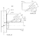
- FIG. 2A shows a beam-column-brace joined by a gusset assembly 200, according to one embodiment of the invention.
- the gusset assembly 200 includes two gusset plates 200a/200b separated by a gap.
- the gap should be wide enough to provide enough free movement without collision of the two gusset plates 200a/200b. In some embodiments, width of the gap ranges from 12 mm - 300 mm, or more commonly between 25 mm - 100 mm.
- Gusset plate 200b is fixedly connected to the beam Bm by, for example, welding thereto, and likewise, gusset plate 200a is welded the column C.
- the diagonal brace Br is bolted to both gusset plates using a plurality of bolts 202.
- the column C, beam Bm, and brace Br are prefabricated structural elements, such as I-beams or tubes. It should be understood that use of the term “bolt” is meant to include a variety of fasteners such as bolt/nut combinations, screws, rivets, etc.
- the gusset plates 200a/200b can be constructed from a high strength materials such as steel plate or composites. Thickness and other dimensions of the gusset plates 200a/200b can be derived from the requirements of the particular structure that is being constructed, in the same manner as a prior art gusset plate.
- the plurality of bolts 202 are moveably connected within slotted bolt holes 204 of the gusset plates 200a/200b and diagonal brace Br. As assembled, the slotted bolt holes 204 are perpendicular to the shown centerline of the gap G, and thus angularly oriented with regards to the structure as a whole. In some embodiments, curved slots may be used.
- the gap and slots 204 allow the gusset plates 200a/200b to move relative to each other. Accordingly, the beam Bm and column C can move relative to each other (since they are fixedly connected to the gusset plates 200a/200b) effectively as if the gusset was not present, and thus rotate around work point WP1, which is where centerlines of the beam Bm and column C intersect.
- An alternative work point WP2 is placed at where the centerline of the gap G physically intersects the beam Bm and column C joint. This arrangement prevents the transfer of respective dynamic loads applied to the column C and beam Bm to one another via the gusset plates 202a/202b.
- the bolts are secured to the faces of the gusset plates through an overly large hole instead of a slot using large washers.
- a polymer, rubber, or soft-metal O-ring may be situated within this overly large hole to help center the bolt and/or absorb shock, vibrations, and forces.
- the bolts within the slots 204 can be tightened to a degree that is performed with a prior art connection, and in some cases less so or more so. It is expected that earthquake-like forces will be so large to make bolt tightness a non-critical factor. When potentially destructive forces are applied to the gusset assembly 200, it does not behave in the manner depicted in Figure 1A , where bending moment induced shear forces are amplified by presence of the gusset.
- only the diagonal brace Br or the gusset plates 200a/200b include the slots, while the other includes tapped holes for the bolt to directly secure to.
- One advantage is the ability to weld the gusset plates 202a/202b to the beam Bm and column C in a shop (i.e., off the construction site) and simply assemble the components using the bolts 202 in the field (i.e., field bolting on the construction site).
- the prior art arrangement in Figure 1 requires welding on the construction site, which is less reliable and accurate, less controlled, more costly, and more time-consuming than shop welding.
- structural members are prefabricated as much as possible and little to no structural connecting via welding is required at the construction site. For these reasons and more, shop welding and field bolting are strongly preferred in the construction industry.
- Figure 2B shows the same arrangement as Figure 2A with one set of slotted bolt holes 204 in gusset plate 200b being perpendicular to the centerline of the beam Bm, and thus vertically oriented with regards to the structure as a whole.
- the other set of slotted holes 204 in gusset plate 200a are perpendicular to the centerline of the column C, and thus horizontally oriented with regards to the structure as a whole.
- the fixed connection (e.g., weld) at the beam Bm receives horizontal force only (parallel to the weld) and the fixed connection (e.g., weld) at the column C receives vertical force only (parallel to the fixed connection).
- FIGS 2C and 2D show end views of the gusset assembly 200.
- the brace Br can be moveably connected to only one side of the gussets 202a/202b, as depicted in Figure 2C .
- the brace Br can be moveably connected to both sides of the gussets 202a/202b as depicted in Figure 2D .
- Figure 2E shows an embodiment where only one gusset plate include slots 204, while the other gusset plate is fixedly connected (e.g., bolted and/or welded).
- FIGS 3A and 3B show alternative gusset assemblies 300 of the gusset assemblies 200 shown in Figures 2A and 2B , respectively.
- brace Br is configured at an acute angle, and thus the gusset plates 302a/302b are not symmetric about dividing centerline CL.
- the gusset plates 302a/302b are configured such that the dividing centerline CL intersects work point WP1. Accordingly, gusset plate 302a is larger than gusset plate 302b.
- the dividing centerline CL can be shifted in a parallel manner to intersect WP2, as shown in Figure 2A . This alternative embodiment would create a more central gap between the gusset plates 302a/302b than what is shown.
- the gusset assemblies 300 can be constructed as disclosed with regards to gusset plate assembly 200.
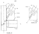
- FIGS 4A and 4B show alternative gusset assemblies 400 of the gusset assemblies 300 shown in Figures 3A and 3B , respectively.
- brace Br is configured at an obtuse angle.
- the gusset plates 302a/302b are configured such that the dividing centerline CL intersects work point WP1. Accordingly, gusset plate 402a is larger than gusset plate 402b.
- the dividing centerline CL can be shifted in a parallel manner to intersect WP2, as shown in Figure 2A . This alternative embodiment would create a more central gap between the gusset plates 402a/402b than what is shown.
- the gusset assemblies 400 can be constructed as disclosed with regards to gusset plate assembly 200.
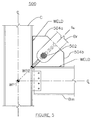
- Figure 5 shows a beam-column-brace joint connected by a gusset assembly 500, according to one embodiment of the invention.
- the diagonal brace Br is connected to the gusset assembly 500 using a single pin 502 instead of a plurality of bolts.
- a semi-circular cut is made in each of the gusset plates 504a/504b along the gap edges to cradle the pin. This connection allows for relative horizontal and vertical relative movement via presence of the gap, which is spaced both horizontally and vertically, as well as rotational relative movement via the pin 500.
- the gusset assembly 500 can be constructed as disclosed with regards to gusset plate assembly 200.
- Figure 6A shows a beam-column-brace assembly connected by a gusset assembly 600, according to one embodiment of the invention.
- the gusset assembly 600 includes a first stub 602 which is fixedly connected to the beam Bm by a fixed connection (e.g., bolting and/or welding).
- a second stub 604 fixedly connected to the column C in a similar fashion.
- a gusset plate 606 is fixedly connected to the brace Br.
- the first stub 602 and the second stub 604 can be constructed from a extruded material, such as steel "angle iron".
- the gusset plate 606 is moveably connected to the first stub 602 using slotted bolt holes 608 that are oriented diagonally (perpendicular to centerline CL). Horizontal and vertical gaps are respectively present between the edges of the gusset plate 606 and the beam Bm and column C. This arrangement allows relative movement of beam Bm and column C, as described herein, and also provides the added advantage of isolating the forces transferred from the brace Br to the beam Bm and column C.
- Figure 6B shows an alternative arrangement of the first stub 602 and the second stub 604 for gusset assembly 600.
- the gusset plate 606 is moveably connected to the first stub 602 using slotted bolt holes 608 that are vertically oriented.
- the gusset plate 606 is moveably connected to the second stub 604 using slotted bolt holes 608 that are horizontally oriented.
- Figures 6C and 6D show alternative arrangements of the attachments of the brace Br to the gusset plate 606.
- Figure 6C shows the brace Br in a bolted configuration.
- Figure 6D shows brace Br pinned to the gusset plate via a large pin, which may be rotatable.
- Figures 6E, 6F, 6G, and 6H various configuration for attachment of the first stub 602 and second stub 604 to the beam Bm and column C, respectively.
- Figures 6E and 6F shows single sided and double sided stub attachment configurations, respectively, that are welded to the beam Br or column C.
- Figures 6G and 6H show single-sided and double-sided stub attachment configurations, respectively, that are bolted to the beam Br or column C.
- FIG. 7A shows a beam-column-brace assembly connected by a gusset assembly 700, according to one embodiment of the invention.
- the gusset assembly 700 is similar to what is disclosed in Figure 2A .
- the gusset assembly 700 includes a first gusset plate 702 fixedly attached to the column C and a second gusset plate 704 fixedly attached to the beam Bm.
- the first gusset plate 702 and the second gusset plate 704 are offset from the centerlines of the beam and the column that bisect their webs, such that the first gusset plate 702 and the second gusset plate 704 slide past each other in different planes.
- the brace Br is bolted to both gusset plates via slotted holes 706 arranged at an angle (perpendicular to the centerline of the centerline CL) are used.
- Figures 7B, 7C, and 7D show different arrangements of the gusset assembly 700.
- the first gusset plate 702 and second gusset plate 704 are arranged as shown in Figure 7A , such that brace Br is located therebetween.
- the first gusset plate 702 and second gusset plate 704 can be arranged such that one side of the brace Br is exposed.
- both the first gusset plate 702 and second gusset plate 704 are arranged on the same side of webs of the column C and beam Bm.
- the first gusset plate 702 and second gusset plate 704 can be arranged to contact one another at inner sides, with the brace Br being doubly placed at outer sides.
- FIG 8A shows a beam-column-brace assembly connected by a gusset assembly 800, according to one embodiment of the invention.
- Gusset assembly 800 is similar to gusset assembly 700, but here gusset plates 802 and 804 are interconnected to brace Br by a physical pin. An oversized hole is made in gusset plates 802 and 804 that allows them to move perpendicular the centerline CL of the brace Br.
- Figures 8B-8D respectively show that the brace Br can be sandwiched between the two gusset plates 802 and 804, or be on one side of the gusset plates 802 and 804, or the brace Br having a forked end can sandwich both gusset plates 802 and 804.
- Figure 9A shows a beam-column-brace assembly connected by a gusset assembly 900, according to one embodiment of the invention.
- Figure 9A shows a new configuration of the invention (similar to the one depicted in Figure 6 ) with the gusset assembly 900 having three plates.
- the first plate 902 is fixedly connected to the beam Bm and a second plate 904 is fixedly connected to the column C.
- a third (or main) plate 906 is fixedly connected to the brace Br (in this case welded).
- the third plate 906 is moveably connected to the first plate 904 via slotted bolt holes arranged perpendicular to the centerline of the brace Br.
- the third plate 906 is also moveably connected to the second plate 904 via slotted bolt holes arranged perpendicular to the centerline of the brace Br. Gaps exist between the edge of the third plate 906 and both the beam Bm and column C.
- the third plate 906 can be furnished as a single plate portion bolted to one side of the first and second plates 902/904, such that it only contacts one of the first and second plates, or the third plate can be arranged as two plate portions sandwiching the first and second plates 902/904 welded to the beam Bm and column C.
- Figure 9B and Figure 9C show alternative arrangements for connecting the brace Br to the third plate 906, by a physical pin and bolting, respectively.
- Figure 9D shows the same beam-column-brace assembly of Figure 9A with the slotted bolt holes in second plate 904 being parallel to the beam Bm and the slotted holes in the first plate being parallel to the column C.
- This arrangement may provide the added advantage of isolating the forces transferred from the brace to the beam and column as outlined in Figure 2B .
- Embodiments of the invention are not limited to beam Bm and column C joints.
- Figure 10 shows two different configurations of gusset assemblies for attaching a brace Br to a mid-portion of a beam Bm (where two braces Br meet at a beam Bm). Two different gusset assemblies are shown for the sake of brevity, in some embodiments this may be the case, and in other embodiments the configurations can be identical.
- the left hand side shows a gusset assembly 1000, which is similar to the one depicted in Figure 2A .
- the right hand side shows a gusset assembly 1010, which has a configuration similar to the one depicted in Figure 6A .
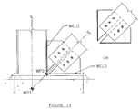
- Figure 11 is another example of an application of the invention to a different portion of a building structure.
- the gusset assembly disclosed in Figure 2A is applied to a column-brace-base plate location. It should be understood, that all the gusset assemblies disclosed herein can be applied at the column-brace-base plate location by replacing a beam with a base plate in the disclosed figures.
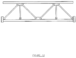
- Embodiments of the invention are not limited to building structures, but can be applied to many load bearing structures that typically use beam and column construction.
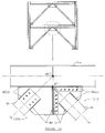
- Figure 12 shows a typical truss. Any of the joints shown can be constructed according to the embodiments disclosed herein.
- embodiments of the invention are constructed according to known techniques for structural building construction.
Applications Claiming Priority (2)
| Application Number | Priority Date | Filing Date | Title |
|---|---|---|---|
| US201161442738P | 2011-02-14 | 2011-02-14 | |
| PCT/US2012/025122 WO2012112608A2 (en) | 2011-02-14 | 2012-02-14 | Split gusset connection |
Publications (3)
| Publication Number | Publication Date |
|---|---|
| EP2675960A2 EP2675960A2 (en) | 2013-12-25 |
| EP2675960A4 EP2675960A4 (en) | 2014-07-16 |
| EP2675960B1 true EP2675960B1 (en) | 2016-06-29 |
Family
ID=46673134
Family Applications (1)
| Application Number | Title | Priority Date | Filing Date |
|---|---|---|---|
| EP12746785.0A Active EP2675960B1 (en) | 2011-02-14 | 2012-02-14 | Split gusset connection |
Country Status (7)
| Country | Link |
|---|---|
| US (3) | US9856640B2 (ja) |
| EP (1) | EP2675960B1 (ja) |
| JP (1) | JP6030581B2 (ja) |
| KR (1) | KR101940298B1 (ja) |
| CN (1) | CN103620128B (ja) |
| CA (1) | CA2826767C (ja) |
| WO (1) | WO2012112608A2 (ja) |
Families Citing this family (33)
| Publication number | Priority date | Publication date | Assignee | Title |
|---|---|---|---|---|
| DE102012106772A1 (de) * | 2012-07-25 | 2014-01-30 | Thyssenkrupp Steel Europe Ag | Modularer Turm einer Windkraftanlage |
| CA2898340C (en) | 2012-11-30 | 2018-02-13 | Mitek Holdings, Inc. | Gusset plate connection of beam to column |
| US9506239B2 (en) | 2012-11-30 | 2016-11-29 | Mitek Holdings, Inc. | Gusset plate connection in bearing of beam to column |
| DE102014107323A1 (de) * | 2014-05-23 | 2015-11-26 | Terex Mhps Gmbh | Kranträger für einen Kran, insbesondere für einen Brücken- oder Portalkran, und einen Kran hiermit |
| US9631357B2 (en) * | 2015-02-26 | 2017-04-25 | Allen Brb, Llc | Systems and methods for fabrication and use of brace designs for braced frames |
| CN104912222B (zh) * | 2015-05-13 | 2017-11-24 | 华南理工大学 | 一种双节点板夹持式防屈曲支撑栓焊混合连接节点 |
| US20160356033A1 (en) | 2015-06-03 | 2016-12-08 | Mitek Holdings, Inc | Gusset plate connection of braced beam to column |
| CN204876096U (zh) * | 2015-08-13 | 2015-12-16 | 广东菲思科金属科技有限公司 | 铝合金房屋的立柱与横梁螺栓连接结构 |
| US10190271B2 (en) * | 2015-10-13 | 2019-01-29 | University Of Notre Dame Du Lac | Adjustable modules for variable depth structures |
| CN105386521B (zh) * | 2015-11-26 | 2017-09-22 | 孙本新 | 可组装为楼房框架的梁与柱模块 |
| US20170314254A1 (en) | 2016-05-02 | 2017-11-02 | Mitek Holdings, Inc. | Moment resisting bi-axial beam-to-column joint connection |
| CN105822019A (zh) * | 2016-05-20 | 2016-08-03 | 西安建筑科技大学 | 一种带外伸盖板梁支撑双侧板节点 |
| US11236502B2 (en) | 2016-10-03 | 2022-02-01 | Mitek Holdings, Inc. | Gusset plate and column assembly for moment resisting bi-axial beam-to-column joint connections |
| US10179991B2 (en) | 2016-10-03 | 2019-01-15 | Mitek Holdings, Inc. | Forming column assemblies for moment resisting bi-axial beam-to-column joint connections |
| US20180238041A1 (en) | 2017-02-21 | 2018-08-23 | Styrc Jacek | Modular furniture system |
| JP6944348B2 (ja) * | 2017-11-08 | 2021-10-06 | 日本軽金属株式会社 | 制震装置の取付構造 |
| USD887025S1 (en) | 2017-11-17 | 2020-06-09 | 2724889 Ontario Inc. | Connector for a modular structure |
| US11396746B2 (en) | 2019-06-14 | 2022-07-26 | Quaketek Inc. | Beam coupler operating as a seismic brake, seismic energy dissipation device and seismic damage control device |
| KR102096744B1 (ko) * | 2019-07-03 | 2020-04-03 | (주)아이오컨스텍 | 수평, 수직 및 회전오차 수용이 가능한 강가로보 |
| USD936859S1 (en) | 2020-02-04 | 2021-11-23 | 2724889 Ontario Inc. | Connector |
| USD952384S1 (en) | 2020-02-04 | 2022-05-24 | 2724889 Ontario Inc. | Leg |
| USD952382S1 (en) | 2020-02-04 | 2022-05-24 | 2724889 Ontario Inc. | Table |
| USD938770S1 (en) | 2020-02-04 | 2021-12-21 | 2724889 Ontario Inc. | Connector |
| USD938771S1 (en) | 2020-02-04 | 2021-12-21 | 2724889 Ontario Inc. | Connector |
| USD938772S1 (en) | 2020-02-04 | 2021-12-21 | 2724889 Ontario Inc. | Connector |
| CN111749368A (zh) * | 2020-06-30 | 2020-10-09 | 中冶(上海)钢结构科技有限公司 | 一种装配式级联支撑抗侧体系及其作业方法 |
| USD936861S1 (en) | 2020-08-12 | 2021-11-23 | 2724889 Ontario Inc. | Connector for a modular structure |
| USD939731S1 (en) | 2020-08-12 | 2021-12-28 | 2724889 Ontario Inc. | Connector for a modular structure |
| USD938068S1 (en) | 2020-08-12 | 2021-12-07 | 2724889 Ontario Inc. | Connector for a modular structure |
| USD936247S1 (en) | 2020-08-12 | 2021-11-16 | 2724889 Ontario Inc. | Connector for a modular structure |
| USD939106S1 (en) * | 2020-08-12 | 2021-12-21 | 2724889 Ontario Inc. | Connector for a modular structure |
| USD936246S1 (en) | 2020-08-12 | 2021-11-16 | 2724889 Ontario Inc. | Connector for a modular structure |
| USD938619S1 (en) | 2020-08-12 | 2021-12-14 | 2724889 Ontario Inc. | Connector for a modular structure |
Family Cites Families (26)
| Publication number | Priority date | Publication date | Assignee | Title |
|---|---|---|---|---|
| US4014089A (en) * | 1975-02-21 | 1977-03-29 | Kajima Corporation | Method of connecting beams and columns of steel frame construction |
| US4409765A (en) * | 1980-06-24 | 1983-10-18 | Pall Avtar S | Earth-quake proof building construction |
| US5660017A (en) * | 1994-12-13 | 1997-08-26 | Houghton; David L. | Steel moment resisting frame beam-to-column connections |
| JPH09125517A (ja) * | 1995-10-30 | 1997-05-13 | Daiki:Kk | 柱枠組の補強装置 |
| JPH09209477A (ja) * | 1996-02-07 | 1997-08-12 | Taisei Corp | 建物のフレームとブレースとの共振防止接合構造 |
| JP2987331B2 (ja) | 1996-07-22 | 1999-12-06 | 株式会社鴻池組 | 粘弾性ダンパーを用いたブレース構造 |
| US6474902B1 (en) * | 1997-01-22 | 2002-11-05 | Icf Kaiser Engineers, Inc. | Connector for connecting beams to columns |
| JP2000186371A (ja) | 1998-12-22 | 2000-07-04 | Kajima Corp | 柱・梁とブレース材との接合構造 |
| US6516583B1 (en) * | 1999-03-26 | 2003-02-11 | David L. Houghton | Gusset plate connections for structural braced systems |
| JP2001107458A (ja) | 1999-10-08 | 2001-04-17 | Daiya Reform Kk | 木造建築物の耐震補強金具 |
| JP2003049558A (ja) * | 2001-08-07 | 2003-02-21 | Kazuhiko Kasai | 制振間柱 |
| US20050055969A1 (en) * | 2002-03-18 | 2005-03-17 | Simmons Robert J. | Building frame structure |
| US6837010B2 (en) | 2002-12-05 | 2005-01-04 | Star Seismic, Llc | Pin and collar connection apparatus for use with seismic braces, seismic braces including the pin and collar connection, and methods |
| JP4376088B2 (ja) * | 2003-02-28 | 2009-12-02 | 新日本製鐵株式会社 | 梁継手構造 |
| JP4044483B2 (ja) * | 2003-04-25 | 2008-02-06 | 新日本製鐵株式会社 | ガセットプレートを用いた構造物の接合構造および建築物 |
| US20050005561A1 (en) * | 2003-07-11 | 2005-01-13 | Nucon Steel Corporation | Lateral and uplift resistance apparatus and methods for use in structural framing |
| JP4649250B2 (ja) * | 2004-11-26 | 2011-03-09 | 新日鉄エンジニアリング株式会社 | 耐震補強用接合構造 |
| US8468775B2 (en) * | 2006-03-10 | 2013-06-25 | Willaim B. Vaughn | Moment resistant building column insert system and method |
| JP4649360B2 (ja) | 2006-04-07 | 2011-03-09 | 新日本製鐵株式会社 | 耐震用接合構造及びその構築方法 |
| US7712266B2 (en) * | 2007-05-22 | 2010-05-11 | Skidmore Owings & Merrill Llp | Seismic structural device |
| US8365476B2 (en) * | 2007-12-28 | 2013-02-05 | Seismic Structural Design Associates, Inc. | Braced frame force distribution connection |
| JP2009209477A (ja) | 2008-03-04 | 2009-09-17 | Kao Corp | 繊維処理剤組成物 |
| JP4203533B1 (ja) * | 2008-03-05 | 2009-01-07 | 株式会社アイ.テック | 鉄骨柱及び鉄骨梁の接合構造 |
| US20100005749A1 (en) * | 2008-07-09 | 2010-01-14 | King Solomon Creative Enterprises Corp. | Steel building frame system |
| US8800239B2 (en) * | 2010-04-19 | 2014-08-12 | Weihong Yang | Bolted steel connections with 3-D jacket plates and tension rods |
| JP5822262B2 (ja) * | 2011-06-30 | 2015-11-24 | 住友林業株式会社 | 梁勝ち接合部における柱梁接合構造 |
-
2012
- 2012-02-14 CN CN201280008650.XA patent/CN103620128B/zh active Active
- 2012-02-14 US US14/006,963 patent/US9856640B2/en active Active
- 2012-02-14 WO PCT/US2012/025122 patent/WO2012112608A2/en active Application Filing
- 2012-02-14 CA CA2826767A patent/CA2826767C/en active Active
- 2012-02-14 KR KR1020137024224A patent/KR101940298B1/ko active IP Right Grant
- 2012-02-14 EP EP12746785.0A patent/EP2675960B1/en active Active
- 2012-02-14 JP JP2013553663A patent/JP6030581B2/ja active Active
-
2017
- 2017-10-03 US US15/724,072 patent/US10294657B2/en active Active
-
2019
- 2019-05-20 US US16/417,365 patent/US11060274B2/en active Active
Also Published As
| Publication number | Publication date |
|---|---|
| CA2826767C (en) | 2019-07-23 |
| CN103620128B (zh) | 2017-06-30 |
| EP2675960A4 (en) | 2014-07-16 |
| JP2014505190A (ja) | 2014-02-27 |
| US10294657B2 (en) | 2019-05-21 |
| US11060274B2 (en) | 2021-07-13 |
| JP6030581B2 (ja) | 2016-11-24 |
| KR101940298B1 (ko) | 2019-01-18 |
| KR20140034762A (ko) | 2014-03-20 |
| US20180087264A1 (en) | 2018-03-29 |
| EP2675960A2 (en) | 2013-12-25 |
| CN103620128A (zh) | 2014-03-05 |
| US9856640B2 (en) | 2018-01-02 |
| US20140318075A1 (en) | 2014-10-30 |
| US20190271145A1 (en) | 2019-09-05 |
| CA2826767A1 (en) | 2012-08-23 |
| WO2012112608A3 (en) | 2012-10-18 |
| WO2012112608A2 (en) | 2012-08-23 |
Similar Documents
| Publication | Publication Date | Title |
|---|---|---|
| US11060274B2 (en) | Split gusset connection | |
| US11332920B2 (en) | Moment resisting bi-axial beam-to-column joint connection | |
| US9353525B1 (en) | Semi-rigid connections for braced frames | |
| US9631357B2 (en) | Systems and methods for fabrication and use of brace designs for braced frames | |
| CA3063748C (en) | Rolling block restraint connector | |
| US20130001383A1 (en) | Spaced t primary member-to-primary member connection | |
| KR200186312Y1 (ko) | 트러스 구조체 | |
| JP2013245442A (ja) | 外殻構造 | |
| JP6645328B2 (ja) | H形鋼の接合構造及びそれに用いられるh形鋼 | |
| JP2018104884A (ja) | 建物の補強構造及び補強方法 | |
| JP5667775B2 (ja) | 建物 | |
| JP2007309020A (ja) | 鉄骨片持ち梁と鉄骨小梁の接合構造 | |
| JP7211915B2 (ja) | 耐震補強構造 | |
| JP7162457B2 (ja) | あと付けブレースの接合構造 | |
| JP2019039201A (ja) | あと付けブレースの接合構造 | |
| JP2014114549A (ja) | 落橋防止装置 | |
| JP2023094933A (ja) | 柱梁接合構造および柱梁接合構造の製造方法 | |
| JP2022156475A (ja) | 鋼製耐震壁及びこれを備えた建物、並びに鋼製耐震壁の取付方法 | |
| JP2023167918A (ja) | 柱構造 | |
| JP2002348957A (ja) | 鉄骨骨組構造 | |
| DoWsWell et al. | Horizontal Bracing | |
| JP2017203307A (ja) | ブレース接合構造 | |
| JPH1061016A (ja) | ユニット住宅 |
Legal Events
| Date | Code | Title | Description |
|---|---|---|---|
| PUAI | Public reference made under article 153(3) epc to a published international application that has entered the european phase |
Free format text: ORIGINAL CODE: 0009012 |
|
| 17P | Request for examination filed |
Effective date: 20130903 |
|
| AK | Designated contracting states |
Kind code of ref document: A2 Designated state(s): AL AT BE BG CH CY CZ DE DK EE ES FI FR GB GR HR HU IE IS IT LI LT LU LV MC MK MT NL NO PL PT RO RS SE SI SK SM TR |
|
| DAX | Request for extension of the european patent (deleted) | ||
| A4 | Supplementary search report drawn up and despatched |
Effective date: 20140618 |
|
| RIC1 | Information provided on ipc code assigned before grant |
Ipc: E04C 3/04 20060101ALN20140612BHEP Ipc: E04B 1/38 20060101ALI20140612BHEP Ipc: E04B 1/24 20060101AFI20140612BHEP Ipc: E04H 9/02 20060101ALI20140612BHEP Ipc: E04B 1/58 20060101ALI20140612BHEP |
|
| REG | Reference to a national code |
Ref country code: HK Ref legal event code: DE Ref document number: 1192909 Country of ref document: HK |
|
| 17Q | First examination report despatched |
Effective date: 20150610 |
|
| GRAP | Despatch of communication of intention to grant a patent |
Free format text: ORIGINAL CODE: EPIDOSNIGR1 |
|
| RIC1 | Information provided on ipc code assigned before grant |
Ipc: E04B 1/38 20060101ALI20151029BHEP Ipc: E04C 3/04 20060101ALN20151029BHEP Ipc: E04H 9/02 20060101ALI20151029BHEP Ipc: E04B 1/58 20060101ALI20151029BHEP Ipc: E04B 1/24 20060101AFI20151029BHEP |
|
| RIC1 | Information provided on ipc code assigned before grant |
Ipc: E04B 1/38 20060101ALI20151030BHEP Ipc: E04B 1/24 20060101AFI20151030BHEP Ipc: E04C 3/04 20060101ALN20151030BHEP Ipc: E04H 9/02 20060101ALI20151030BHEP Ipc: E04B 1/58 20060101ALI20151030BHEP |
|
| INTG | Intention to grant announced |
Effective date: 20151118 |
|
| RIC1 | Information provided on ipc code assigned before grant |
Ipc: E04B 1/58 20060101ALI20151110BHEP Ipc: E04H 9/02 20060101ALI20151110BHEP Ipc: E04C 3/04 20060101ALN20151110BHEP Ipc: E04B 1/24 20060101AFI20151110BHEP Ipc: E04B 1/38 20060101ALI20151110BHEP |
|
| GRAS | Grant fee paid |
Free format text: ORIGINAL CODE: EPIDOSNIGR3 |
|
| GRAP | Despatch of communication of intention to grant a patent |
Free format text: ORIGINAL CODE: EPIDOSNIGR1 |
|
| RIC1 | Information provided on ipc code assigned before grant |
Ipc: E04B 1/58 20060101ALI20160408BHEP Ipc: E04C 3/04 20060101ALN20160408BHEP Ipc: E04B 1/38 20060101ALI20160408BHEP Ipc: E04B 1/24 20060101AFI20160408BHEP Ipc: E04H 9/02 20060101ALI20160408BHEP |
|
| GRAS | Grant fee paid |
Free format text: ORIGINAL CODE: EPIDOSNIGR3 |
|
| GRAA | (expected) grant |
Free format text: ORIGINAL CODE: 0009210 |
|
| INTG | Intention to grant announced |
Effective date: 20160503 |
|
| AK | Designated contracting states |
Kind code of ref document: B1 Designated state(s): AL AT BE BG CH CY CZ DE DK EE ES FI FR GB GR HR HU IE IS IT LI LT LU LV MC MK MT NL NO PL PT RO RS SE SI SK SM TR |
|
| REG | Reference to a national code |
Ref country code: GB Ref legal event code: FG4D |
|
| REG | Reference to a national code |
Ref country code: CH Ref legal event code: EP |
|
| REG | Reference to a national code |
Ref country code: AT Ref legal event code: REF Ref document number: 809229 Country of ref document: AT Kind code of ref document: T Effective date: 20160715 |
|
| REG | Reference to a national code |
Ref country code: IE Ref legal event code: FG4D |
|
| REG | Reference to a national code |
Ref country code: DE Ref legal event code: R096 Ref document number: 602012019990 Country of ref document: DE |
|
| REG | Reference to a national code |
Ref country code: LT Ref legal event code: MG4D |
|
| PG25 | Lapsed in a contracting state [announced via postgrant information from national office to epo] |
Ref country code: NO Free format text: LAPSE BECAUSE OF FAILURE TO SUBMIT A TRANSLATION OF THE DESCRIPTION OR TO PAY THE FEE WITHIN THE PRESCRIBED TIME-LIMIT Effective date: 20160929 Ref country code: FI Free format text: LAPSE BECAUSE OF FAILURE TO SUBMIT A TRANSLATION OF THE DESCRIPTION OR TO PAY THE FEE WITHIN THE PRESCRIBED TIME-LIMIT Effective date: 20160629 Ref country code: LT Free format text: LAPSE BECAUSE OF FAILURE TO SUBMIT A TRANSLATION OF THE DESCRIPTION OR TO PAY THE FEE WITHIN THE PRESCRIBED TIME-LIMIT Effective date: 20160629 |
|
| REG | Reference to a national code |
Ref country code: NL Ref legal event code: MP Effective date: 20160629 |
|
| PG25 | Lapsed in a contracting state [announced via postgrant information from national office to epo] |
Ref country code: SE Free format text: LAPSE BECAUSE OF FAILURE TO SUBMIT A TRANSLATION OF THE DESCRIPTION OR TO PAY THE FEE WITHIN THE PRESCRIBED TIME-LIMIT Effective date: 20160629 Ref country code: NL Free format text: LAPSE BECAUSE OF FAILURE TO SUBMIT A TRANSLATION OF THE DESCRIPTION OR TO PAY THE FEE WITHIN THE PRESCRIBED TIME-LIMIT Effective date: 20160629 Ref country code: LV Free format text: LAPSE BECAUSE OF FAILURE TO SUBMIT A TRANSLATION OF THE DESCRIPTION OR TO PAY THE FEE WITHIN THE PRESCRIBED TIME-LIMIT Effective date: 20160629 Ref country code: GR Free format text: LAPSE BECAUSE OF FAILURE TO SUBMIT A TRANSLATION OF THE DESCRIPTION OR TO PAY THE FEE WITHIN THE PRESCRIBED TIME-LIMIT Effective date: 20160930 Ref country code: HR Free format text: LAPSE BECAUSE OF FAILURE TO SUBMIT A TRANSLATION OF THE DESCRIPTION OR TO PAY THE FEE WITHIN THE PRESCRIBED TIME-LIMIT Effective date: 20160629 Ref country code: RS Free format text: LAPSE BECAUSE OF FAILURE TO SUBMIT A TRANSLATION OF THE DESCRIPTION OR TO PAY THE FEE WITHIN THE PRESCRIBED TIME-LIMIT Effective date: 20160629 |
|
| REG | Reference to a national code |
Ref country code: AT Ref legal event code: MK05 Ref document number: 809229 Country of ref document: AT Kind code of ref document: T Effective date: 20160629 |
|
| REG | Reference to a national code |
Ref country code: FR Ref legal event code: PLFP Year of fee payment: 6 |
|
| PG25 | Lapsed in a contracting state [announced via postgrant information from national office to epo] |
Ref country code: SK Free format text: LAPSE BECAUSE OF FAILURE TO SUBMIT A TRANSLATION OF THE DESCRIPTION OR TO PAY THE FEE WITHIN THE PRESCRIBED TIME-LIMIT Effective date: 20160629 Ref country code: IS Free format text: LAPSE BECAUSE OF FAILURE TO SUBMIT A TRANSLATION OF THE DESCRIPTION OR TO PAY THE FEE WITHIN THE PRESCRIBED TIME-LIMIT Effective date: 20161029 Ref country code: RO Free format text: LAPSE BECAUSE OF FAILURE TO SUBMIT A TRANSLATION OF THE DESCRIPTION OR TO PAY THE FEE WITHIN THE PRESCRIBED TIME-LIMIT Effective date: 20160629 Ref country code: EE Free format text: LAPSE BECAUSE OF FAILURE TO SUBMIT A TRANSLATION OF THE DESCRIPTION OR TO PAY THE FEE WITHIN THE PRESCRIBED TIME-LIMIT Effective date: 20160629 Ref country code: CZ Free format text: LAPSE BECAUSE OF FAILURE TO SUBMIT A TRANSLATION OF THE DESCRIPTION OR TO PAY THE FEE WITHIN THE PRESCRIBED TIME-LIMIT Effective date: 20160629 Ref country code: IT Free format text: LAPSE BECAUSE OF FAILURE TO SUBMIT A TRANSLATION OF THE DESCRIPTION OR TO PAY THE FEE WITHIN THE PRESCRIBED TIME-LIMIT Effective date: 20160629 |
|
| PG25 | Lapsed in a contracting state [announced via postgrant information from national office to epo] |
Ref country code: ES Free format text: LAPSE BECAUSE OF FAILURE TO SUBMIT A TRANSLATION OF THE DESCRIPTION OR TO PAY THE FEE WITHIN THE PRESCRIBED TIME-LIMIT Effective date: 20160629 Ref country code: AT Free format text: LAPSE BECAUSE OF FAILURE TO SUBMIT A TRANSLATION OF THE DESCRIPTION OR TO PAY THE FEE WITHIN THE PRESCRIBED TIME-LIMIT Effective date: 20160629 Ref country code: BE Free format text: LAPSE BECAUSE OF FAILURE TO SUBMIT A TRANSLATION OF THE DESCRIPTION OR TO PAY THE FEE WITHIN THE PRESCRIBED TIME-LIMIT Effective date: 20160629 Ref country code: PT Free format text: LAPSE BECAUSE OF FAILURE TO SUBMIT A TRANSLATION OF THE DESCRIPTION OR TO PAY THE FEE WITHIN THE PRESCRIBED TIME-LIMIT Effective date: 20161031 Ref country code: SM Free format text: LAPSE BECAUSE OF FAILURE TO SUBMIT A TRANSLATION OF THE DESCRIPTION OR TO PAY THE FEE WITHIN THE PRESCRIBED TIME-LIMIT Effective date: 20160629 Ref country code: PL Free format text: LAPSE BECAUSE OF FAILURE TO SUBMIT A TRANSLATION OF THE DESCRIPTION OR TO PAY THE FEE WITHIN THE PRESCRIBED TIME-LIMIT Effective date: 20160629 |
|
| REG | Reference to a national code |
Ref country code: DE Ref legal event code: R097 Ref document number: 602012019990 Country of ref document: DE |
|
| PLBE | No opposition filed within time limit |
Free format text: ORIGINAL CODE: 0009261 |
|
| STAA | Information on the status of an ep patent application or granted ep patent |
Free format text: STATUS: NO OPPOSITION FILED WITHIN TIME LIMIT |
|
| PG25 | Lapsed in a contracting state [announced via postgrant information from national office to epo] |
Ref country code: DK Free format text: LAPSE BECAUSE OF FAILURE TO SUBMIT A TRANSLATION OF THE DESCRIPTION OR TO PAY THE FEE WITHIN THE PRESCRIBED TIME-LIMIT Effective date: 20160629 |
|
| 26N | No opposition filed |
Effective date: 20170330 |
|
| STAA | Information on the status of an ep patent application or granted ep patent |
Free format text: STATUS: NO OPPOSITION FILED WITHIN TIME LIMIT |
|
| PG25 | Lapsed in a contracting state [announced via postgrant information from national office to epo] |
Ref country code: BG Free format text: LAPSE BECAUSE OF FAILURE TO SUBMIT A TRANSLATION OF THE DESCRIPTION OR TO PAY THE FEE WITHIN THE PRESCRIBED TIME-LIMIT Effective date: 20160929 Ref country code: SI Free format text: LAPSE BECAUSE OF FAILURE TO SUBMIT A TRANSLATION OF THE DESCRIPTION OR TO PAY THE FEE WITHIN THE PRESCRIBED TIME-LIMIT Effective date: 20160629 |
|
| PG25 | Lapsed in a contracting state [announced via postgrant information from national office to epo] |
Ref country code: MC Free format text: LAPSE BECAUSE OF FAILURE TO SUBMIT A TRANSLATION OF THE DESCRIPTION OR TO PAY THE FEE WITHIN THE PRESCRIBED TIME-LIMIT Effective date: 20160629 |
|
| REG | Reference to a national code |
Ref country code: CH Ref legal event code: PL |
|
| PG25 | Lapsed in a contracting state [announced via postgrant information from national office to epo] |
Ref country code: CH Free format text: LAPSE BECAUSE OF NON-PAYMENT OF DUE FEES Effective date: 20170228 Ref country code: LI Free format text: LAPSE BECAUSE OF NON-PAYMENT OF DUE FEES Effective date: 20170228 |
|
| REG | Reference to a national code |
Ref country code: IE Ref legal event code: MM4A |
|
| PG25 | Lapsed in a contracting state [announced via postgrant information from national office to epo] |
Ref country code: LU Free format text: LAPSE BECAUSE OF NON-PAYMENT OF DUE FEES Effective date: 20170214 |
|
| PG25 | Lapsed in a contracting state [announced via postgrant information from national office to epo] |
Ref country code: IE Free format text: LAPSE BECAUSE OF NON-PAYMENT OF DUE FEES Effective date: 20170214 |
|
| REG | Reference to a national code |
Ref country code: HK Ref legal event code: GR Ref document number: 1192909 Country of ref document: HK |
|
| REG | Reference to a national code |
Ref country code: FR Ref legal event code: PLFP Year of fee payment: 7 |
|
| PG25 | Lapsed in a contracting state [announced via postgrant information from national office to epo] |
Ref country code: MT Free format text: LAPSE BECAUSE OF NON-PAYMENT OF DUE FEES Effective date: 20170214 |
|
| PG25 | Lapsed in a contracting state [announced via postgrant information from national office to epo] |
Ref country code: AL Free format text: LAPSE BECAUSE OF FAILURE TO SUBMIT A TRANSLATION OF THE DESCRIPTION OR TO PAY THE FEE WITHIN THE PRESCRIBED TIME-LIMIT Effective date: 20160629 |
|
| PG25 | Lapsed in a contracting state [announced via postgrant information from national office to epo] |
Ref country code: HU Free format text: LAPSE BECAUSE OF FAILURE TO SUBMIT A TRANSLATION OF THE DESCRIPTION OR TO PAY THE FEE WITHIN THE PRESCRIBED TIME-LIMIT; INVALID AB INITIO Effective date: 20120214 |
|
| PG25 | Lapsed in a contracting state [announced via postgrant information from national office to epo] |
Ref country code: CY Free format text: LAPSE BECAUSE OF NON-PAYMENT OF DUE FEES Effective date: 20160629 |
|
| PG25 | Lapsed in a contracting state [announced via postgrant information from national office to epo] |
Ref country code: MK Free format text: LAPSE BECAUSE OF FAILURE TO SUBMIT A TRANSLATION OF THE DESCRIPTION OR TO PAY THE FEE WITHIN THE PRESCRIBED TIME-LIMIT Effective date: 20160629 |
|
| PG25 | Lapsed in a contracting state [announced via postgrant information from national office to epo] |
Ref country code: TR Free format text: LAPSE BECAUSE OF FAILURE TO SUBMIT A TRANSLATION OF THE DESCRIPTION OR TO PAY THE FEE WITHIN THE PRESCRIBED TIME-LIMIT Effective date: 20160629 |
|
| PGFP | Annual fee paid to national office [announced via postgrant information from national office to epo] |
Ref country code: FR Payment date: 20230228 Year of fee payment: 12 |
|
| PGFP | Annual fee paid to national office [announced via postgrant information from national office to epo] |
Ref country code: GB Payment date: 20230216 Year of fee payment: 12 Ref country code: DE Payment date: 20230222 Year of fee payment: 12 |