EP2675020A1 - Connector and mounting method therefor - Google Patents
Connector and mounting method therefor Download PDFInfo
- Publication number
- EP2675020A1 EP2675020A1 EP13002330.2A EP13002330A EP2675020A1 EP 2675020 A1 EP2675020 A1 EP 2675020A1 EP 13002330 A EP13002330 A EP 13002330A EP 2675020 A1 EP2675020 A1 EP 2675020A1
- Authority
- EP
- European Patent Office
- Prior art keywords
- wire
- wires
- bracket
- housing
- cover
- Prior art date
- Legal status (The legal status is an assumption and is not a legal conclusion. Google has not performed a legal analysis and makes no representation as to the accuracy of the status listed.)
- Granted
Links
- 238000000034 method Methods 0.000 title claims description 12
- 238000003780 insertion Methods 0.000 claims description 24
- 230000037431 insertion Effects 0.000 claims description 24
- 230000013011 mating Effects 0.000 description 10
- 230000005540 biological transmission Effects 0.000 description 7
- 238000004519 manufacturing process Methods 0.000 description 6
- 230000006866 deterioration Effects 0.000 description 4
- 230000002093 peripheral effect Effects 0.000 description 4
- 230000000717 retained effect Effects 0.000 description 4
- 229920003002 synthetic resin Polymers 0.000 description 3
- 239000000057 synthetic resin Substances 0.000 description 3
- 230000000694 effects Effects 0.000 description 2
- 239000000463 material Substances 0.000 description 2
- 239000002184 metal Substances 0.000 description 2
- 238000003825 pressing Methods 0.000 description 2
- 238000007789 sealing Methods 0.000 description 2
- 238000005299 abrasion Methods 0.000 description 1
- 238000005452 bending Methods 0.000 description 1
- 238000000576 coating method Methods 0.000 description 1
- 239000004020 conductor Substances 0.000 description 1
- 230000001419 dependent effect Effects 0.000 description 1
- 230000000149 penetrating effect Effects 0.000 description 1
- 229920005989 resin Polymers 0.000 description 1
- 239000011347 resin Substances 0.000 description 1
Images





Classifications
-
- H—ELECTRICITY
- H01—ELECTRIC ELEMENTS
- H01R—ELECTRICALLY-CONDUCTIVE CONNECTIONS; STRUCTURAL ASSOCIATIONS OF A PLURALITY OF MUTUALLY-INSULATED ELECTRICAL CONNECTING ELEMENTS; COUPLING DEVICES; CURRENT COLLECTORS
- H01R13/00—Details of coupling devices of the kinds covered by groups H01R12/70 or H01R24/00 - H01R33/00
- H01R13/58—Means for relieving strain on wire connection, e.g. cord grip, for avoiding loosening of connections between wires and terminals within a coupling device terminating a cable
- H01R13/5804—Means for relieving strain on wire connection, e.g. cord grip, for avoiding loosening of connections between wires and terminals within a coupling device terminating a cable comprising a separate cable clamping part
-
- H—ELECTRICITY
- H01—ELECTRIC ELEMENTS
- H01R—ELECTRICALLY-CONDUCTIVE CONNECTIONS; STRUCTURAL ASSOCIATIONS OF A PLURALITY OF MUTUALLY-INSULATED ELECTRICAL CONNECTING ELEMENTS; COUPLING DEVICES; CURRENT COLLECTORS
- H01R13/00—Details of coupling devices of the kinds covered by groups H01R12/70 or H01R24/00 - H01R33/00
- H01R13/58—Means for relieving strain on wire connection, e.g. cord grip, for avoiding loosening of connections between wires and terminals within a coupling device terminating a cable
- H01R13/5837—Means for relieving strain on wire connection, e.g. cord grip, for avoiding loosening of connections between wires and terminals within a coupling device terminating a cable specially adapted for accommodating various sized cables
-
- H—ELECTRICITY
- H01—ELECTRIC ELEMENTS
- H01R—ELECTRICALLY-CONDUCTIVE CONNECTIONS; STRUCTURAL ASSOCIATIONS OF A PLURALITY OF MUTUALLY-INSULATED ELECTRICAL CONNECTING ELEMENTS; COUPLING DEVICES; CURRENT COLLECTORS
- H01R13/00—Details of coupling devices of the kinds covered by groups H01R12/70 or H01R24/00 - H01R33/00
- H01R13/73—Means for mounting coupling parts to apparatus or structures, e.g. to a wall
- H01R13/74—Means for mounting coupling parts in openings of a panel
- H01R13/748—Means for mounting coupling parts in openings of a panel using one or more screws
-
- H—ELECTRICITY
- H01—ELECTRIC ELEMENTS
- H01R—ELECTRICALLY-CONDUCTIVE CONNECTIONS; STRUCTURAL ASSOCIATIONS OF A PLURALITY OF MUTUALLY-INSULATED ELECTRICAL CONNECTING ELEMENTS; COUPLING DEVICES; CURRENT COLLECTORS
- H01R2201/00—Connectors or connections adapted for particular applications
- H01R2201/26—Connectors or connections adapted for particular applications for vehicles
Definitions
- the present invention relates to a connector and mounting method therefor.
- a connector disclosed in Japanese Unexamined Patent Publication No. H11-219758 is known as a connector to be mounted on an end of a wire.
- This connector includes a terminal fitting connected to the end of the wire and a housing formed with a cavity into which this terminal fitting is to be accommodated from behind.
- the terminal fitting is stopped so as not to move any further forward by a front stop portion provided in the cavity and locked by a resin locking lance provided in the cavity from behind, thereby being retained in the housing.
- the terminal fitting Since the terminal fitting is mounted as a separate component into the housing, a clearance is present between the terminal fitting and the inner wall of the cavity and it is unavoidable that the terminal fitting slightly shakes in the cavity.
- the wire and a connector housing vibrate as the vehicle runs.
- terminal fittings shake in forward and backward directions in the cavity, with the result that sliding abrasion occurs in connecting parts between the terminal fittings and connection reliability between the terminal fittings is reduced.
- the present invention was completed in view of the above situation and an object thereof is to suppress sliding movements between terminal fittings and improve connection reliability between the terminal fittings by preventing the shaking of wires.
- a connector to be mounted on an end of a wire to be installed in a vehicle comprising at least one terminal fitting which is to be connected to the end of the wire; a housing in which the terminal fitting is at least partly accommodated and from which the wire is drawn out; and a bracket which fixes (is suitable to fix) the housing to a case of a device installed in the vehicle; wherein the bracket includes a wire fixing portion for fixing the wire extending in a direction intersecting with an extending direction of the wire in a vibrating part where the wire vibrates as the vehicle vibrates between a wire draw-out part where the wire is drawn out from the housing and the vibrating part.
- the wire fixing portion fixes the wire extending in a direction to be able to cancel vibration in the extending of the wire transmitted from the vibrating part between the wire draw-out part and the vibrating part.
- the transmission of the vibration from the vibrating part to the wire draw-out part can be suppressed. This can suppress the shaking of the terminal fitting in the housing and sliding movements between terminal fittings. Consequently, connection reliability between the terminal fittings can be improved.
- the present invention is preferably embodied as follows.
- the wire fixing portion may fix the wire by tightening the wire.
- the wire can be reliably fixed to the wire fixing portion without being affected by the thickness and the like of the wire and the transmission of vibration from the vibrating part to the wire draw-out part can be reliably suppressed. Further, it is not necessary to change the shape of the wire fixing portion according to the thickness and the like of the wire and it is possible to reduce a burden in parts management and manufacturing cost.
- the wire fixing portion may fix the wire extending in a direction intersecting with an insertion direction in which the terminal fitting is inserted into the housing. According to such a configuration, even if vibration from the vibrating part is transmitted beyond the wire fixing portion, the transmission of the vibration to the terminal fitting is further suppressed and the shaking of the terminal fitting in the insertion direction of the terminal fitting in the housing can be further suppressed since the terminal fitting is inserted in the direction intersecting with the vibration in the extending direction of the wire in the wire fixing portion. This can further suppress sliding movements between the terminal fittings due to the shaking of the terminal fitting in the insertion direction of the terminal fitting.
- a cover for covering and protecting the wire draw-out part of the housing may be attached to the bracket, and/or the wire fixing portion may be provided integrally to the cover.
- the transmission of vibration from the vibrating part to the wire draw-out part can be suppressed by providing the cover for protecting the wire with the wire fixing portion.
- the cover for protecting the wire can double as the wire fixing portion for fixing the wire by providing the wire fixing portion integrally or unitarily to the cover. This can reduce manufacturing cost more than in the case where the wire fixing portion for fixing the wire is separately provided.
- the cover may cover a part of the housing from the wire draw-out part to the wire fixing portion.
- the deterioration of the wire fixing portion and the wire due to exposure to the elements can be prevented since not only a part where the wire is drawn out, but also a part where the wire is fixed can be covered. This can suppress the transmission of vibration from the vibrating part to the terminal fitting due to a reduction in a fixing force for the wire resulting from the deterioration of the wire fixing portion and the wire.
- the bracket may be fixed to the case by tightening at least one tightening member into the case, and the cover may be fixed to the case by being tightened together with the bracket by the tightening member.
- the cover and the bracket can be assembled with the case by one tightening operation. This can reduce the manufacturing cost and the number of operation steps of the connector.
- the bracket may include a mounting seat for attaching the cover to the bracket in advance before the bracket is attached to the case.
- the connector can be transported with the cover including the wire fixing portion attached to the bracket. This can prevent parts management such as individual transportation of the housing assembled with the bracket and the cover from becoming cumbersome and the connector from being damaged due to the wire drawn out from the housing being caught by another member or the like.
- the bracket may be a shield bracket.
- a method of mounting a connector in particular according to the above aspect of the invention or a particular embodiment thereof, to an end of a wire to be installed in a vehicle, comprising the following steps: connecting at least one terminal fitting to the end of the wire; at least partly accommodating the terminal fitting into a housing such that the wire is drawn out of the housing; providing a bracket which is suitable to fix the housing to a case of a device installed in the vehicle; and fixing by means of a wire fixing portion of the bracket the wire extending in a direction intersecting with an extending direction of the wire in a vibrating part where the wire vibrates as the vehicle vibrates between a wire draw-out part where the wire is drawn out from the housing and the vibrating part.
- the wire is fixed by tightening the wire.
- the wire is fixed extending in a direction intersecting with an insertion direction in which the terminal fitting is inserted into the housing.
- the method further comprises covering and protecting the wire draw-out part of the housing by means of a cover which is attached to the bracket; and/or wherein the wire fixing portion is provided integrally to the cover.
- a part of the housing from the wire draw-out part to the wire fixing portion is covered by means of the cover.
- bracket is fixed to the case by tightening at least one tightening member into the case; and the cover is fixed to the case by being tightened together with the bracket by the tightening member.
- the method further comprises attaching the cover to the bracket by means of a mounting seat of the bracket in advance before the bracket is attached to the case.
- FIGS. 1 to 10 A first particular embodiment of the present invention is described with reference to FIGS. 1 to 10 .
- a connector 10 which is connected to one or more ends of one or more respective wires W1 to be arranged in a vehicle and to be mounted on a case (not shown) of a device to be installed in the vehicle.
- the connector 10 includes one or more female terminals (an example of a "terminal fitting") 20 to be connected to the ends of the wires W1, a housing 30 made e.g. of synthetic resin and configured to at least partly accommodate one or more, particularly a plurality of female terminals 20, a shield bracket 40 (as an example of a "bracket") particularly made of conductive material such as metal and configured to at least partly cover the housing 30 and/or a cover 50 made e.g. of synthetic resin and to be attached to the shield bracket 40.
- vertical direction is based on FIGS. 2 , 4 and 10
- forward and backward directions are based on FIG. 10
- a side to be mounted on the case of the device shown right side in FIG. 10
- a front side a side to be mounted on the case of the device
- the wires W1 are at least partly covered by a covering member W2 as shown in FIGS. 7 and 10 , and a plurality of (three in this embodiment) wires W are arranged in the vehicle while being at least partly covered together by the covering member W2.
- the plurality of wires W1 are exposed at an end of the covering member W2 and the respective female terminals 20 are connected (particularly crimped and connected) to cores exposed by stripping coatings of the respective wires W1, whereby the female terminals 20 are electrically connected to the respective wires W1.
- the housing 30 includes a housing main body 31 (particularly substantially having an elliptical shape long in a lateral direction) and one or more (e.g. three) fitting portions 32 integrally or unitarily formed to or on the housing main body 31.
- the particularly plural (e.g. three) fitting portions 32 substantially are arranged side by side in the lateral direction LD and each of them extends forward from the front surface of the housing main body 31.
- a (particularly substantially cylindrical) seal 33 for sealing between a mating connector and the fitting portion 32 when the connector 10 is connected to the mating connector particularly is mounted on the outer periphery of each fitting portion 32.
- a cavity 34 penetrating through the fitting portion 32 in forward and backward directions is provided in the fitting portion 32.
- the female terminal 20 connected to the wire W1 at least partly is inserted into the cavity 34 from behind and the wire W1 is drawn out backward from a rear end part of the housing main body 31. That is, a draw-out direction DOD of the wire W1 and an insertion direction ID of the female terminal 20 into the cavity 34 particularly substantially are the same or parallel to each other.
- the female terminal 20 is to be electrically connected to a mating terminal (not shown) provided in the mating connector when the fitting portion 32 and the mating connector are connected. Further, a locking lance (not shown) formed in the cavity 34 at least partly is fitted into a locking hole (not shown) provided in the female terminal 20, whereby the female terminal 20 is retained so as not to come off backward. Note that a small clearance is secured between the locking lance and the locking hole to enable the locking lance to be smoothly fitted into the locking hole.
- a rubber ring 35 (as a particular resilient ring) retained so as not to come off backward by a seal ring 36 particularly is mounted in a rear end part of the cavity 34. This rubber ring 35 is to be held in close contact with the inner peripheral surface of the cavity 34 and the outer peripheral surface of the wire W1, thereby sealing between the inner peripheral wall of the cavity 34 and the wire W1.
- the shield bracket 40 particularly is formed by press-working or stamping a plate material, such as a conductive (particularly metal) plate material, and/or includes a tubular portion 41 to be externally fitted on the housing main body 31 to at least partly cover the housing main body 31 (particularly over the substantially entire circumference) and a flange portion (an example of a "mounting portion") 42 projecting outward from a front end part of the tubular portion 41.
- a plate material such as a conductive (particularly metal) plate material
- the tubular portion 41 is mounted onto the housing main body 31 from behind and a rear end part of the tubular portion 41 is locked by one or more, particularly a plurality of locking portions 31A provided on (particularly the rear end part of) the housing main body 31, whereby the shield bracket 40 is or can be fixed so as not to come off from the housing main body 31.
- a shield layer such as braided wire (not shown) can be connected (particularly crimped and connected) to the outer periphery of the tubular portion 41.
- the shield layer (particularly the braided wire) collectively covering the wires W drawn out from the housing main body 31 is connected (particularly crimped and connected) to the tubular portion 41, whereby the plurality of wires W1 are shielded together.
- the flange portion 42 is formed with one or more, particularly a plurality of (two in this embodiment) bolt insertion holes 43.
- the shield bracket 40 is fixed to the case e.g. by inserting one or more bolts (an example of a "tightening member” or “fixing member”) B through the bolt insertion holes 43 and tightening them into the case as shown in FIG. 8 .
- the cover 50 includes a covering portion 51 for at least partly covering a wire draw-out part P1 where the one or more, particularly plurality of wires W1 are drawn out from the housing main body 1 from behind at the back side of the housing main body 31, and one or more, particularly a pair of upper and lower bulging portions 52 bulging outward from (particularly the upper and/or lower edges of) the covering portion 51.
- the (particularly each) bulging portion 52 is provided with a screw insertion hole 53 into which a screw S is insertable.
- the flange portion 42 of the shield bracket 40 includes one or more mounting seats 44 at respective positions corresponding to the screw insertion hole(s) 53 respectively provided in the (particularly pair of) bulging portion(s) 52, and a screw hole 44A to be threadably engaged with the screw S is formed to penetrate through the (particularly each) mounting seat 44 in forward and backward directions.
- the shield bracket 40 is so assembled with the cover 40 that the bulging portion(s) 52 correspond(s) to the mounting seat(s) 44, and the screw(s) S is/are inserted through the screw insertion hole(s) 53 and screwed into the screw hole(s) 44A of the mounting seat(s) 44, whereby the cover 50 is fixed to the shield bracket 40. That is, before the shield bracket 40 is fixed to the case of the device, the cover 50 can be fixed to the shield bracket 40 in advance. This can prevent parts management such as individual transportation of the housing 30 assembled with the shield bracket 40 and the cover 50 from becoming cumbersome and the connector 10 from being damaged due to the contact of other members with the wires W1 drawn out from the housing main body 31 during the transportation of the connector 10.
- the covering portion 51 is in the form of a receptacle which is open forward, and formed to particularly protect the substantially entire wire draw-out part P1 of the housing main body 31 particularly by at least partly accommodating the tubular portion 41 of the shield bracket 40 together with the housing main body 31 of the housing 30 particularly substantially from behind.
- the covering portion 51 includes a lower opening 51A through which the wires W1 are drawn out while being bent in an extending direction ED (e.g. downward) to be at an angle different from 0° or 180°, preferably substantially perpendicular to the draw-out direction DOD of the plurality of wires W1 (wire draw-out part P1) drawn out (e.g. backward) from the housing main body 31.
- the plurality of wires W1 drawn out downward from this lower opening 51A are bent at an angle different from 0° or 180°, preferably substantially normal or to the right and arranged to extend in the lateral direction LD in the vehicle.
- the cover 50 includes a wire fixing portion 54 for collectively bundling and fixing at least part of the plurality of wires W1 drawn out downward from the lower opening 51A of the covering portion 51 and extending in the extending direction ED (e.g. the vertical direction).
- the wire fixing portion 54 is provided on or near (particularly a lower end part of) the covering portion 51 and includes a support recess 55 extending outward or downward from (particularly the lower end part of) the covering portion 51 and a tightening band 56 (as a particular tightening member) made e.g. of synthetic resin and/or configured to tighten the plurality of wires W1 together.
- the wire fixing portion 54 is arranged below parts R1 (as particular first parts) of the plurality of wires W1 drawn out in the draw-out direction DOD (e.g. substantially backward) from the housing main body 31, which are bent downward to be at an angle different from 0° or 180°, preferably substantially perpendicular to the draw-out direction DOD of the wires W1, and above parts R2 (as particular second parts) of the wires W1 bent (e.g. upward) to be at an angle different from 0° or 180°, preferably substantially perpendicular to the extending direction ED of the wires W1 arranged to extend in the lateral direction LD in the vehicle.
- the support recess 55 is formed by halving a (particularly substantially cylindrical) body and formed integrally or unitary to (particularly the lower end part of) the covering portion 51 while being open laterally or forward.
- the plurality of wires W1 drawn out downward from the covering portion 51 and extending in the extending direction ED can be arranged on the inner side (front side) of the support recess 55 and, as shown in FIG. 8 , one or more, particularly a pair of (left and/or right) band insertion holes 57 are provided in the rear wall of the support recess 55.
- a tightening band 56 through the (particularly pair of left and/or right) band insertion hole(s) 57 of the support recess 55 (e.g.
- the plurality of wires W1 are or can be firmly fixed to the support recess 55.
- the wires W1 drawn out in the extending direction ED or substantially downward from the covering portion 51 are firmly fixed by the wire fixing portion 54 while extending in the extending direction ED at an angle different from 0° or 180°, preferably substantially perpendicular to the draw-out direction DOD of the plurality of wires W1 drawn out (e.g.
- a wire holding portion 58 for holding the covering member W2 at least partly covering the wires W1 together is provided on a lower end part of the wire fixing portion 54.
- the wire holding portion 58 includes a groove portion 59 formed to be continuous with the support recess 55 and a retaining portion 60 for at least partly closing a front side of the groove portion 59.
- the groove portion 59 is open (e.g. substantially forward) like the support recess 55.
- One or more, particularly a pair of left and right holding projections 61 substantially in conformity with the shape of the covering member W2 are provided on the front end opening edge of the groove portion 59, and the covering member W2 is held by the wire holding portion 58 by this/these holding projection(s) 61, particularly this pair of holding projections 61, supporting the covering member W2 arranged in the groove portion 59 from front.
- the retaining portion 60 is provided on (particularly the front opening edge of) the groove portion 59 via at least one hinge. By bending the hinge(s) and closing and locking the front opening edge of the groove portion 59 after the covering member W2 is press-fitted and held into the groove portion 59, the covering member W2 particularly is retained so as not to come off forward. That is, the wire holding portion 58 fixes the covering member W2 covering the plurality of wires W1 together in addition to the wire fixing portion 54 for fixing the wires W1.
- the connector 10 of this embodiment is configured as described above. Next, functions and effects of the connector 10 are described.
- the connector 10 is fixed to the case of the device installed in the vehicle and the plurality of wires W1 drawn out in the extending direction ED (e.g. substantially downward) from the connector 10 are bent to at an angle different from 0° or 180°, preferably substantially normal or laterally or the left and arranged to the extend in the wire vehicle extension direction WVED (e.g. substantially in the lateral direction LD) in the vehicle while being at least partly covered by the covering member W2 as shown in FIG. 8 .
- the wires W1 arranged to extend in the wire vehicle extension direction WVED (particularly substantially the lateral direction LD) in the vehicle largely vibrates in the wire vehicle extension direction WVED (particularly substantially in the lateral direction LD) together with the covering member W2 as the vehicle runs. Vibration (particularly lateral vibration) from a vibrating part P2 where the wires W1 vibrate in the wire vehicle extension direction WVED (particularly substantially in the lateral direction LD) affects also the connector 10 connected to the ends of the wires W1.
- the wire fixing portion 54 provided between the wire draw-out part P1 of the housing main body 31 where the wires W1 are drawn out and the vibrating part (wires W1 arranged to extend in the wire vehicle extension direction WVED (particularly substantially in the lateral direction LD) in the vehicle) P2 firmly fixes the wires W1 extending in the wire vehicle extension direction WVED, particularly substantially in the vertical direction. That is, since the wires W1 are fixed while extending in the extending direction ED particularly substantially in the vertical direction, which is an inclined, particularly a substantially perpendicular direction capable of canceling lateral vibration in this embodiment, the transmission of the (particularly substantially lateral) vibration from the vibrating part P2 to the wire draw-out part P1 can be suppressed.
- the extending wires W1 arranged in the extending direction ED are fixed by being tightened in a radial direction of the wires W1 by the tightening band 56 in the wire fixing portion 54, the wires W1 are not shifted in the same direction as the vibrating direction (the wire vehicle extension direction WVED) unlike the case where wires are fixed while extending in the same direction as the vibrating direction, wherefore the (lateral) vibration from the vibrating part P2 can be reliably suppressed. In this way, it is possible to suppress sliding movements between the female terminals 20 and the mating terminals and improve connection reliability between the terminals.
- the wires W1 particularly are fixed by the tightening band 56 (as a particular tightening member) according to this embodiment it is not necessary to change the shape of the wire fixing portion 54 according to the thickness and number of the wires W1 and it is possible to reduce a burden in parts management and manufacturing cost.
- the wires W1 are so fixed that the extending direction ED of the wires W1 in the wire fixing portion 54 (vertical direction) and the draw-out direction DOD of the wires W1 drawn out from the housing main body 31 (forward and backward directions) are at an angle different from 0° or 180°, preferably substantially perpendicular.
- the lateral vibration transmitted from the wire fixing portion 54 is canceled or strongly reduced and the transmission thereof to the wires W1 drawn out from the housing main body 31 in forward and backward directions can be further suppressed.
- the female terminals 20 shake in forward and backward directions, which is the insertion direction ID of the female terminals 20, in the housing 30.
- This can further suppress sliding movements occurring between the female terminals 20 and the mating terminals and further improve connection reliability between the terminals.
- the cover 50 has both a protection function of protecting the wire draw-out part P1 and a wire fixing function of fixing the wires W1 by providing the cover 50 for protecting the wire draw-out part P1 with the wire fixing portion 54.
- manufacturing cost can be reduced as compared with the case where a cover for protecting the wire draw-out part P1 and a wire fixing portion for fixing the wires W1 are separately provided.
- a connector 10 to be mounted on one or more ends of wires W1 to be installed in a vehicle includes one or more female terminals 20 which are to be connected to the ends of the wires, a housing 30 in which the one or more female terminals 20 are to be at least partly accommodated and from which the one or more wires W1 are drawn out, and a bracket (particularly a shield bracket) 40 which fixes the housing 30 to a case of a device installed in the vehicle.
- the shield bracket 40 includes a wire fixing portion 54 for fixing the wire(s) W1 extending in an extending direction ED (particularly substantially a vertical direction) at an angle different from 0° or 180°, preferably substantially perpendicular to a wire vehicle extension direction WVED or an extending direction of the wires W1 in a vibrating part P2 where the wire(s) W1 vibrate(s) as the vehicle vibrate(s) between a wire draw-out part P1 where the wire(s) W1 are drawn out from the housing 30 and the vibrating part P2.
- a wire fixing portion 54 for fixing the wire(s) W1 extending in an extending direction ED (particularly substantially a vertical direction) at an angle different from 0° or 180°, preferably substantially perpendicular to a wire vehicle extension direction WVED or an extending direction of the wires W1 in a vibrating part P2 where the wire(s) W1 vibrate(s) as the vehicle vibrate(s) between a wire draw-out part P1 where the wire
- FIGS. 11 to 18 Next, a second particular embodiment of the present invention is described with reference to FIGS. 11 to 18 .
- the shape of the flange portion 42 of the shield bracket 40, the shape(s) of the wire fixing portion 54 and/or the wire holding portion 58 of the cover 50 and/or the shape(s) of the bulging portion(s) 52 of the cover 50 in the first embodiment is/are changed as shown in FIGS. 14 to 18 .
- the components, functions and effects common or similar to the first embodiment are not repeatedly described. Further, the similar or substantially same components as in the first embodiment are denoted by the same reference signs.
- a flange portion 142 of a shield bracket 140 of the second embodiment particularly is made smaller in size than the flange portion 42 of the first embodiment by being formed with less bolt insertion hole(s) 143 (e.g. only with two bolt insertion holes 143) particularly while omitting the mounting seat(s) 44 unlike in the first embodiment.
- one or more bulging portions 152 of a cover 150 of the second embodiment are shaped to (particularly substantially completely) cover the flange portion 142 of the shield bracket 140 as shown in FIGS. 14 to 18 .
- the bulging portion(s) 152 is/are (particularly each) formed with a cover-side bolt insertion hole 163 having substantially the same diameter as bolt insertion hole(s) 143 provided in the flange portion 142 of the shield bracket 140 particularly unlike the screw insertion hole(s) 53 of the first embodiment.
- FIG. 13 the bulging portion(s) 152 is/are (particularly each) formed with a cover-side bolt insertion hole 163 having substantially the same diameter as bolt insertion hole(s) 143 provided in the flange portion 142 of the shield bracket 140 particularly unlike the screw insertion hole(s) 53 of the first embodiment.
- the cover-side bolt insertion hole(s) 163 particularly is/are formed at position(s) corresponding to the bolt insertion hole(s) 143 of the flange portion 142 when the cover 150 is assembled with the shield bracket 140, and the cover 150 is fixed to both the shield bracket 140 and a case of a device by one or more inserting bolts (an example of a "tightening member” or “fixing member”) successively through the cover-side bolt insertion hole(s) 163 and the bolt insertion hole(s) 143 and fixing (particularly tightening) it/them into the case.
- inserting bolts an example of a "tightening member” or “fixing member
- both the cover 150 and the shield bracket 140 can be fixed to the case by one bolt tightening operation. In this way, the manufacturing cost and the number of operation steps of the connector 110 can be reduced.
- a wire fixing portion 154 and a wire holding portion 158 of the cover 150 of the second embodiment include a lid portion 162 for closing a front opening of a support recess 155 and a front opening of a groove portion 159 together as shown in FIG. 14 .
- the lid portion 162 particularly is formed to completely close from a lower opening 51 A of a covering portion 51 to a lower end part of the wire holding portion 158 and mounted on the support recess 156 and/or the groove portion 159 from front by respectively engaging one or more, particularly a plurality of locking projections 164 formed on (particularly a peripheral edge part of) the lid portion 162 with one or more, particularly a plurality of respective engaging portions 165 formed on (particularly the front opening edge of) the support recess 155 and/or (particularly the front end opening of) the groove portion 159 as shown in FIGS. 15 to 17 .
- wires W1 from the lower opening 51A of the covering portion 51 to the lower end part of the wire holding portion 158 and an end of a covering member W2 particularly are substantially completely covered over the entire circumference by the support recess 155, the groove portion 159 and the lid portion 162 as shown in FIGS. 14 , 17 and 18 .
- the connector 110 is exposed to the elements, it is possible to reliably suppress the adhesion of rain and mud to the wires W1 and the end of the covering member W2. This can suppress a reduction in a fixing force for the wires W1 in the wire fixing portion 154 due to the deterioration of a housing 30 and the wires W1 resulting from the exposure of the connector 110 to the elements.
Landscapes
- Details Of Connecting Devices For Male And Female Coupling (AREA)
- Connector Housings Or Holding Contact Members (AREA)
Abstract
Description
- The present invention relates to a connector and mounting method therefor.
- Conventionally, a connector disclosed in Japanese Unexamined Patent Publication No.
H11-219758 - Since the terminal fitting is mounted as a separate component into the housing, a clearance is present between the terminal fitting and the inner wall of the cavity and it is unavoidable that the terminal fitting slightly shakes in the cavity. In addition, in the case of mounting a connector to a wiring harness to be installed, for example, in a vehicle, the wire and a connector housing vibrate as the vehicle runs. Thus, even after the connector is connected to a mating connector, terminal fittings shake in forward and backward directions in the cavity, with the result that sliding abrasion occurs in connecting parts between the terminal fittings and connection reliability between the terminal fittings is reduced.
- The present invention was completed in view of the above situation and an object thereof is to suppress sliding movements between terminal fittings and improve connection reliability between the terminal fittings by preventing the shaking of wires.
- This object is solved according to the invention by the features of the independent claims. Particular embodiments of the invention are subject of the dependent claims.
- According to one aspect of the invention, there is provided a connector to be mounted on an end of a wire to be installed in a vehicle, comprising at least one terminal fitting which is to be connected to the end of the wire; a housing in which the terminal fitting is at least partly accommodated and from which the wire is drawn out; and a bracket which fixes (is suitable to fix) the housing to a case of a device installed in the vehicle; wherein the bracket includes a wire fixing portion for fixing the wire extending in a direction intersecting with an extending direction of the wire in a vibrating part where the wire vibrates as the vehicle vibrates between a wire draw-out part where the wire is drawn out from the housing and the vibrating part.
- According to the connector thus configured, the wire fixing portion fixes the wire extending in a direction to be able to cancel vibration in the extending of the wire transmitted from the vibrating part between the wire draw-out part and the vibrating part. Thus, the transmission of the vibration from the vibrating part to the wire draw-out part can be suppressed. This can suppress the shaking of the terminal fitting in the housing and sliding movements between terminal fittings. Consequently, connection reliability between the terminal fittings can be improved.
- The present invention is preferably embodied as follows.
- The wire fixing portion may fix the wire by tightening the wire.
- According to such a configuration, the wire can be reliably fixed to the wire fixing portion without being affected by the thickness and the like of the wire and the transmission of vibration from the vibrating part to the wire draw-out part can be reliably suppressed. Further, it is not necessary to change the shape of the wire fixing portion according to the thickness and the like of the wire and it is possible to reduce a burden in parts management and manufacturing cost.
- The wire fixing portion may fix the wire extending in a direction intersecting with an insertion direction in which the terminal fitting is inserted into the housing. According to such a configuration, even if vibration from the vibrating part is transmitted beyond the wire fixing portion, the transmission of the vibration to the terminal fitting is further suppressed and the shaking of the terminal fitting in the insertion direction of the terminal fitting in the housing can be further suppressed since the terminal fitting is inserted in the direction intersecting with the vibration in the extending direction of the wire in the wire fixing portion. This can further suppress sliding movements between the terminal fittings due to the shaking of the terminal fitting in the insertion direction of the terminal fitting.
- A cover for covering and protecting the wire draw-out part of the housing may be attached to the bracket, and/or the wire fixing portion may be provided integrally to the cover.
- According to such a configuration, the transmission of vibration from the vibrating part to the wire draw-out part can be suppressed by providing the cover for protecting the wire with the wire fixing portion.
- Further, the cover for protecting the wire can double as the wire fixing portion for fixing the wire by providing the wire fixing portion integrally or unitarily to the cover. This can reduce manufacturing cost more than in the case where the wire fixing portion for fixing the wire is separately provided.
- The cover may cover a part of the housing from the wire draw-out part to the wire fixing portion.
- According to such a configuration, the deterioration of the wire fixing portion and the wire due to exposure to the elements can be prevented since not only a part where the wire is drawn out, but also a part where the wire is fixed can be covered. This can suppress the transmission of vibration from the vibrating part to the terminal fitting due to a reduction in a fixing force for the wire resulting from the deterioration of the wire fixing portion and the wire.
- The bracket may be fixed to the case by tightening at least one tightening member into the case, and the cover may be fixed to the case by being tightened together with the bracket by the tightening member.
- According to such a configuration, it is not necessary to separately provide a part for attaching the cover to the bracket. Further, the cover and the bracket can be assembled with the case by one tightening operation. This can reduce the manufacturing cost and the number of operation steps of the connector.
- The bracket may include a mounting seat for attaching the cover to the bracket in advance before the bracket is attached to the case.
- According to such a configuration, the connector can be transported with the cover including the wire fixing portion attached to the bracket. This can prevent parts management such as individual transportation of the housing assembled with the bracket and the cover from becoming cumbersome and the connector from being damaged due to the wire drawn out from the housing being caught by another member or the like.
- The bracket may be a shield bracket.
- According to another aspect of the invention, there is provided a method of mounting a connector, in particular according to the above aspect of the invention or a particular embodiment thereof, to an end of a wire to be installed in a vehicle, comprising the following steps: connecting at least one terminal fitting to the end of the wire; at least partly accommodating the terminal fitting into a housing such that the wire is drawn out of the housing; providing a bracket which is suitable to fix the housing to a case of a device installed in the vehicle; and fixing by means of a wire fixing portion of the bracket the wire extending in a direction intersecting with an extending direction of the wire in a vibrating part where the wire vibrates as the vehicle vibrates between a wire draw-out part where the wire is drawn out from the housing and the vibrating part.
- According to a particular embodiment, the wire is fixed by tightening the wire.
- Particularly, the wire is fixed extending in a direction intersecting with an insertion direction in which the terminal fitting is inserted into the housing.
- Further particularly, the method further comprises covering and protecting the wire draw-out part of the housing by means of a cover which is attached to the bracket; and/or wherein the wire fixing portion is provided integrally to the cover.
- Further particularly, a part of the housing from the wire draw-out part to the wire fixing portion is covered by means of the cover.
- Further particularly, the bracket is fixed to the case by tightening at least one tightening member into the case; and the cover is fixed to the case by being tightened together with the bracket by the tightening member.
- Further particularly, the method further comprises attaching the cover to the bracket by means of a mounting seat of the bracket in advance before the bracket is attached to the case.
- According to the above, it is possible to suppress sliding movements between terminal fittings and improve connection reliability between the terminal fittings by preventing the shaking of wires.
- These and other objects, features and advantages of the present invention will become more apparent upon reading of the following detailed description of preferred embodiments and accompanying drawings. It should be understood that even though embodiments are separately described, single features thereof may be combined to additional embodiments.
-
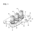
FIG. 1 is a perspective view showing a state where a shield bracket is mounted on a housing according to a first embodiment, -
FIG. 2 is a side view showing the state ofFIG. 1 , -
FIG. 3 is a rear view showing the state ofFIG. 1 , -
FIG. 4 is a front view of a cover according to the first embodiment, -
FIG. 5 is a side view of the cover, -
FIG. 6 is a rear view of the cover, -
FIG. 7 is a front view showing a state where a covering member covering wires is pulled out from a connector according to the first embodiment, -
FIG. 8 is a rear view showing the state ofFIG. 7 , -
FIG. 9 is a bottom view showing the state ofFIG. 7 , -
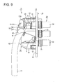
FIG. 10 is a section along A-A ofFIG. 8 , -
FIG. 11 is a perspective view showing a state where a shield bracket is mounted on a housing according to a second embodiment, -
FIG. 12 is a rear view showing the state ofFIG. 11 , -
FIG. 13 is a rear view of a cover according to the second embodiment, -
FIG. 14 is a front view showing a state where a covering member covering wires is pulled out from a connector according to the second embodiment, -
FIG. 15 is a side view showing the state ofFIG. 14 , -
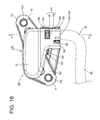
FIG. 16 is a rear view showing the state ofFIG. 14 , -
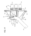
FIG. 17 is a bottom view showing the state ofFIG. 14 , and -
FIG. 18 is a section along B-B ofFIG. 16 . - A first particular embodiment of the present invention is described with reference to
FIGS. 1 to 10 . - In this embodiment is illustrated a
connector 10 which is connected to one or more ends of one or more respective wires W1 to be arranged in a vehicle and to be mounted on a case (not shown) of a device to be installed in the vehicle. - As shown in
FIG. 10 , theconnector 10 includes one or more female terminals (an example of a "terminal fitting") 20 to be connected to the ends of the wires W1, ahousing 30 made e.g. of synthetic resin and configured to at least partly accommodate one or more, particularly a plurality offemale terminals 20, a shield bracket 40 (as an example of a "bracket") particularly made of conductive material such as metal and configured to at least partly cover thehousing 30 and/or acover 50 made e.g. of synthetic resin and to be attached to theshield bracket 40. Note that, in the following description, vertical direction is based onFIGS. 2 ,4 and10 , forward and backward directions are based onFIG. 10 , and a side to be mounted on the case of the device (shown right side inFIG. 10 ) is referred to as a front side. - Specifically, the wires W1 are at least partly covered by a covering member W2 as shown in
FIGS. 7 and10 , and a plurality of (three in this embodiment) wires W are arranged in the vehicle while being at least partly covered together by the covering member W2. - The plurality of wires W1 are exposed at an end of the covering member W2 and the respective
female terminals 20 are connected (particularly crimped and connected) to cores exposed by stripping coatings of the respective wires W1, whereby thefemale terminals 20 are electrically connected to the respective wires W1. - As shown in
FIGS. 1 to 3 , thehousing 30 includes a housing main body 31 (particularly substantially having an elliptical shape long in a lateral direction) and one or more (e.g. three) fittingportions 32 integrally or unitarily formed to or on the housingmain body 31. - The particularly plural (e.g. three) fitting
portions 32 substantially are arranged side by side in the lateral direction LD and each of them extends forward from the front surface of the housingmain body 31. A (particularly substantially cylindrical)seal 33 for sealing between a mating connector and thefitting portion 32 when theconnector 10 is connected to the mating connector particularly is mounted on the outer periphery of eachfitting portion 32. - As shown in
FIG. 10 , acavity 34 penetrating through thefitting portion 32 in forward and backward directions is provided in thefitting portion 32. Thefemale terminal 20 connected to the wire W1 at least partly is inserted into thecavity 34 from behind and the wire W1 is drawn out backward from a rear end part of the housingmain body 31. That is, a draw-out direction DOD of the wire W1 and an insertion direction ID of thefemale terminal 20 into thecavity 34 particularly substantially are the same or parallel to each other. - The
female terminal 20 is to be electrically connected to a mating terminal (not shown) provided in the mating connector when thefitting portion 32 and the mating connector are connected. Further, a locking lance (not shown) formed in thecavity 34 at least partly is fitted into a locking hole (not shown) provided in thefemale terminal 20, whereby thefemale terminal 20 is retained so as not to come off backward. Note that a small clearance is secured between the locking lance and the locking hole to enable the locking lance to be smoothly fitted into the locking hole. - A rubber ring 35 (as a particular resilient ring) retained so as not to come off backward by a
seal ring 36 particularly is mounted in a rear end part of thecavity 34. Thisrubber ring 35 is to be held in close contact with the inner peripheral surface of thecavity 34 and the outer peripheral surface of the wire W1, thereby sealing between the inner peripheral wall of thecavity 34 and the wire W1. - As shown in
FIGS. 2 and10 , theshield bracket 40 particularly is formed by press-working or stamping a plate material, such as a conductive (particularly metal) plate material, and/or includes atubular portion 41 to be externally fitted on the housingmain body 31 to at least partly cover the housing main body 31 (particularly over the substantially entire circumference) and a flange portion (an example of a "mounting portion") 42 projecting outward from a front end part of thetubular portion 41. - The
tubular portion 41 is mounted onto the housingmain body 31 from behind and a rear end part of thetubular portion 41 is locked by one or more, particularly a plurality of lockingportions 31A provided on (particularly the rear end part of) the housingmain body 31, whereby theshield bracket 40 is or can be fixed so as not to come off from the housingmain body 31. Further, a shield layer such as braided wire (not shown) can be connected (particularly crimped and connected) to the outer periphery of thetubular portion 41. The shield layer (particularly the braided wire) collectively covering the wires W drawn out from the housingmain body 31 is connected (particularly crimped and connected) to thetubular portion 41, whereby the plurality of wires W1 are shielded together. - The
flange portion 42 is formed with one or more, particularly a plurality of (two in this embodiment) bolt insertion holes 43. Theshield bracket 40 is fixed to the case e.g. by inserting one or more bolts (an example of a "tightening member" or "fixing member") B through the bolt insertion holes 43 and tightening them into the case as shown inFIG. 8 . - As shown in
FIGS. 9 and10 , thecover 50 includes a coveringportion 51 for at least partly covering a wire draw-out part P1 where the one or more, particularly plurality of wires W1 are drawn out from the housingmain body 1 from behind at the back side of the housingmain body 31, and one or more, particularly a pair of upper and lower bulgingportions 52 bulging outward from (particularly the upper and/or lower edges of) the coveringportion 51. - The (particularly each) bulging
portion 52 is provided with ascrew insertion hole 53 into which a screw S is insertable. On the other hand, theflange portion 42 of theshield bracket 40 includes one or more mountingseats 44 at respective positions corresponding to the screw insertion hole(s) 53 respectively provided in the (particularly pair of) bulging portion(s) 52, and ascrew hole 44A to be threadably engaged with the screw S is formed to penetrate through the (particularly each) mountingseat 44 in forward and backward directions. Theshield bracket 40 is so assembled with thecover 40 that the bulging portion(s) 52 correspond(s) to the mounting seat(s) 44, and the screw(s) S is/are inserted through the screw insertion hole(s) 53 and screwed into the screw hole(s) 44A of the mounting seat(s) 44, whereby thecover 50 is fixed to theshield bracket 40. That is, before theshield bracket 40 is fixed to the case of the device, thecover 50 can be fixed to theshield bracket 40 in advance. This can prevent parts management such as individual transportation of thehousing 30 assembled with theshield bracket 40 and thecover 50 from becoming cumbersome and theconnector 10 from being damaged due to the contact of other members with the wires W1 drawn out from the housingmain body 31 during the transportation of theconnector 10. - The covering
portion 51 is in the form of a receptacle which is open forward, and formed to particularly protect the substantially entire wire draw-out part P1 of the housingmain body 31 particularly by at least partly accommodating thetubular portion 41 of theshield bracket 40 together with the housingmain body 31 of thehousing 30 particularly substantially from behind. Thus, even if theconnector 10 is exposed to the elements, it is possible to suppress the adhesion of rain and mud to the wires W1 and thehousing 30 and the deterioration of the wires W1 and thehousing 30. - Further, as shown in
FIGS. 4 ,7 and9 , the coveringportion 51 includes alower opening 51A through which the wires W1 are drawn out while being bent in an extending direction ED (e.g. downward) to be at an angle different from 0° or 180°, preferably substantially perpendicular to the draw-out direction DOD of the plurality of wires W1 (wire draw-out part P1) drawn out (e.g. backward) from the housingmain body 31. After being covered together by the covering member W2 after extending in the extending direction ED (e.g. downward) a certain short distance, the plurality of wires W1 drawn out downward from thislower opening 51A are bent at an angle different from 0° or 180°, preferably substantially normal or to the right and arranged to extend in the lateral direction LD in the vehicle. - As shown in
FIG. 7 , thecover 50 includes awire fixing portion 54 for collectively bundling and fixing at least part of the plurality of wires W1 drawn out downward from thelower opening 51A of the coveringportion 51 and extending in the extending direction ED (e.g. the vertical direction). Thewire fixing portion 54 is provided on or near (particularly a lower end part of) the coveringportion 51 and includes asupport recess 55 extending outward or downward from (particularly the lower end part of) the coveringportion 51 and a tightening band 56 (as a particular tightening member) made e.g. of synthetic resin and/or configured to tighten the plurality of wires W1 together. That is, thewire fixing portion 54 is arranged below parts R1 (as particular first parts) of the plurality of wires W1 drawn out in the draw-out direction DOD (e.g. substantially backward) from the housingmain body 31, which are bent downward to be at an angle different from 0° or 180°, preferably substantially perpendicular to the draw-out direction DOD of the wires W1, and above parts R2 (as particular second parts) of the wires W1 bent (e.g. upward) to be at an angle different from 0° or 180°, preferably substantially perpendicular to the extending direction ED of the wires W1 arranged to extend in the lateral direction LD in the vehicle. - The
support recess 55 is formed by halving a (particularly substantially cylindrical) body and formed integrally or unitary to (particularly the lower end part of) the coveringportion 51 while being open laterally or forward. - The plurality of wires W1 drawn out downward from the covering
portion 51 and extending in the extending direction ED (e.g. substantially in the vertical direction) can be arranged on the inner side (front side) of thesupport recess 55 and, as shown inFIG. 8 , one or more, particularly a pair of (left and/or right) band insertion holes 57 are provided in the rear wall of thesupport recess 55. By inserting a tighteningband 56 through the (particularly pair of left and/or right) band insertion hole(s) 57 of the support recess 55 (e.g. from behind) and collectively tightening the plurality of wires W1 together with the rear wall of thesupport recess 55 by the tighteningband 56 after the plurality of wires W1 are arranged in or at thesupport recess 55, the plurality of wires W1 are or can be firmly fixed to thesupport recess 55. Specifically, the wires W1 drawn out in the extending direction ED or substantially downward from the coveringportion 51 are firmly fixed by thewire fixing portion 54 while extending in the extending direction ED at an angle different from 0° or 180°, preferably substantially perpendicular to the draw-out direction DOD of the plurality of wires W1 drawn out (e.g. substantially backward) from the housingmain body 31 and in the direction at an angle different from 0° or 180°, preferably substantially perpendicular to a wire vehicle extension direction WVED (particularly substantially the lateral direction LD) in which the wires W1 arranged in the vehicle extend. - Further, a
wire holding portion 58 for holding the covering member W2 at least partly covering the wires W1 together is provided on a lower end part of thewire fixing portion 54. Thewire holding portion 58 includes agroove portion 59 formed to be continuous with thesupport recess 55 and a retainingportion 60 for at least partly closing a front side of thegroove portion 59. Thegroove portion 59 is open (e.g. substantially forward) like thesupport recess 55. One or more, particularly a pair of left and right holdingprojections 61 substantially in conformity with the shape of the covering member W2 are provided on the front end opening edge of thegroove portion 59, and the covering member W2 is held by thewire holding portion 58 by this/these holding projection(s) 61, particularly this pair of holdingprojections 61, supporting the covering member W2 arranged in thegroove portion 59 from front. - The retaining
portion 60 is provided on (particularly the front opening edge of) thegroove portion 59 via at least one hinge. By bending the hinge(s) and closing and locking the front opening edge of thegroove portion 59 after the covering member W2 is press-fitted and held into thegroove portion 59, the covering member W2 particularly is retained so as not to come off forward. That is, thewire holding portion 58 fixes the covering member W2 covering the plurality of wires W1 together in addition to thewire fixing portion 54 for fixing the wires W1. - The
connector 10 of this embodiment is configured as described above. Next, functions and effects of theconnector 10 are described. - The
connector 10 is fixed to the case of the device installed in the vehicle and the plurality of wires W1 drawn out in the extending direction ED (e.g. substantially downward) from theconnector 10 are bent to at an angle different from 0° or 180°, preferably substantially normal or laterally or the left and arranged to the extend in the wire vehicle extension direction WVED (e.g. substantially in the lateral direction LD) in the vehicle while being at least partly covered by the covering member W2 as shown inFIG. 8 . - The wires W1 arranged to extend in the wire vehicle extension direction WVED (particularly substantially the lateral direction LD) in the vehicle largely vibrates in the wire vehicle extension direction WVED (particularly substantially in the lateral direction LD) together with the covering member W2 as the vehicle runs. Vibration (particularly lateral vibration) from a vibrating part P2 where the wires W1 vibrate in the wire vehicle extension direction WVED (particularly substantially in the lateral direction LD) affects also the
connector 10 connected to the ends of the wires W1. Thus, if wires drawn out from a housing are arranged in a vehicle without being fixed to a cover or the like, vibration from a vibrating part is directly transmitted to female terminals of a connector and the female terminals shake in forward and backward directions in cavities, thereby causing sliding movements between the female terminals and mating terminals. Further, even if the wires are fixed to a cover such as by a tightening band, the wires are shifted in the lateral direction in the tightening band and vibration from the vibrating part is transmitted to the female terminals if the vibration from the vibrating part increases when the wires are fixed while extending in the same lateral direction as the direction of the vibration transmitted from the vibrating part. This results in sliding movements between the female terminals and the mating terminals. - However, according to this embodiment, the
wire fixing portion 54 provided between the wire draw-out part P1 of the housingmain body 31 where the wires W1 are drawn out and the vibrating part (wires W1 arranged to extend in the wire vehicle extension direction WVED (particularly substantially in the lateral direction LD) in the vehicle) P2 firmly fixes the wires W1 extending in the wire vehicle extension direction WVED, particularly substantially in the vertical direction. That is, since the wires W1 are fixed while extending in the extending direction ED particularly substantially in the vertical direction, which is an inclined, particularly a substantially perpendicular direction capable of canceling lateral vibration in this embodiment, the transmission of the (particularly substantially lateral) vibration from the vibrating part P2 to the wire draw-out part P1 can be suppressed. Further, since the extending wires W1 arranged in the extending direction ED (particularly substantially vertically) are fixed by being tightened in a radial direction of the wires W1 by the tighteningband 56 in thewire fixing portion 54, the wires W1 are not shifted in the same direction as the vibrating direction (the wire vehicle extension direction WVED) unlike the case where wires are fixed while extending in the same direction as the vibrating direction, wherefore the (lateral) vibration from the vibrating part P2 can be reliably suppressed. In this way, it is possible to suppress sliding movements between thefemale terminals 20 and the mating terminals and improve connection reliability between the terminals. Further, since the wires W1 particularly are fixed by the tightening band 56 (as a particular tightening member) according to this embodiment, it is not necessary to change the shape of thewire fixing portion 54 according to the thickness and number of the wires W1 and it is possible to reduce a burden in parts management and manufacturing cost. - According to this embodiment, in the
wire fixing portion 54, the wires W1 are so fixed that the extending direction ED of the wires W1 in the wire fixing portion 54 (vertical direction) and the draw-out direction DOD of the wires W1 drawn out from the housing main body 31 (forward and backward directions) are at an angle different from 0° or 180°, preferably substantially perpendicular. Thus, even if lateral vibration from the vibrating part P2 is transmitted beyond thewire fixing portion 54, the lateral vibration transmitted from thewire fixing portion 54 is canceled or strongly reduced and the transmission thereof to the wires W1 drawn out from the housingmain body 31 in forward and backward directions can be further suppressed. Specifically, it can be reliably suppressed that thefemale terminals 20 shake in forward and backward directions, which is the insertion direction ID of thefemale terminals 20, in thehousing 30. This can further suppress sliding movements occurring between thefemale terminals 20 and the mating terminals and further improve connection reliability between the terminals. - Further, in this embodiment, the
cover 50 has both a protection function of protecting the wire draw-out part P1 and a wire fixing function of fixing the wires W1 by providing thecover 50 for protecting the wire draw-out part P1 with thewire fixing portion 54. Thus, manufacturing cost can be reduced as compared with the case where a cover for protecting the wire draw-out part P1 and a wire fixing portion for fixing the wires W1 are separately provided. - Accordingly, to prevent sliding movements between terminal fittings and improve connection reliability between the terminal fittings by preventing the shaking of wires, a
connector 10 to be mounted on one or more ends of wires W1 to be installed in a vehicle includes one or morefemale terminals 20 which are to be connected to the ends of the wires, ahousing 30 in which the one or morefemale terminals 20 are to be at least partly accommodated and from which the one or more wires W1 are drawn out, and a bracket (particularly a shield bracket) 40 which fixes thehousing 30 to a case of a device installed in the vehicle. Theshield bracket 40 includes awire fixing portion 54 for fixing the wire(s) W1 extending in an extending direction ED (particularly substantially a vertical direction) at an angle different from 0° or 180°, preferably substantially perpendicular to a wire vehicle extension direction WVED or an extending direction of the wires W1 in a vibrating part P2 where the wire(s) W1 vibrate(s) as the vehicle vibrate(s) between a wire draw-out part P1 where the wire(s) W1 are drawn out from thehousing 30 and the vibrating part P2. - Next, a second particular embodiment of the present invention is described with reference to
FIGS. 11 to 18 . - In a
connector 110 of the second embodiment, the shape of theflange portion 42 of theshield bracket 40, the shape(s) of thewire fixing portion 54 and/or thewire holding portion 58 of thecover 50 and/or the shape(s) of the bulging portion(s) 52 of thecover 50 in the first embodiment is/are changed as shown inFIGS. 14 to 18 . The components, functions and effects common or similar to the first embodiment are not repeatedly described. Further, the similar or substantially same components as in the first embodiment are denoted by the same reference signs. - As shown in
FIGS. 11 and12 , aflange portion 142 of ashield bracket 140 of the second embodiment particularly is made smaller in size than theflange portion 42 of the first embodiment by being formed with less bolt insertion hole(s) 143 (e.g. only with two bolt insertion holes 143) particularly while omitting the mounting seat(s) 44 unlike in the first embodiment. - On the other hand, one or more bulging
portions 152 of acover 150 of the second embodiment are shaped to (particularly substantially completely) cover theflange portion 142 of theshield bracket 140 as shown inFIGS. 14 to 18 . Further, as shown inFIG. 13 ; the bulging portion(s) 152 is/are (particularly each) formed with a cover-sidebolt insertion hole 163 having substantially the same diameter as bolt insertion hole(s) 143 provided in theflange portion 142 of theshield bracket 140 particularly unlike the screw insertion hole(s) 53 of the first embodiment. As shown inFIG. 16 , the cover-side bolt insertion hole(s) 163 particularly is/are formed at position(s) corresponding to the bolt insertion hole(s) 143 of theflange portion 142 when thecover 150 is assembled with theshield bracket 140, and thecover 150 is fixed to both theshield bracket 140 and a case of a device by one or more inserting bolts (an example of a "tightening member" or "fixing member") successively through the cover-side bolt insertion hole(s) 163 and the bolt insertion hole(s) 143 and fixing (particularly tightening) it/them into the case. Specifically, according to this embodiment, it is not necessary to separately provide a part for attaching thecover 150 to theshield bracket 140 and both thecover 150 and theshield bracket 140 can be fixed to the case by one bolt tightening operation. In this way, the manufacturing cost and the number of operation steps of theconnector 110 can be reduced. - Unlike the
wire fixing portion 54 and thewire holding portion 58 of the first embodiment, awire fixing portion 154 and awire holding portion 158 of thecover 150 of the second embodiment include alid portion 162 for closing a front opening of asupport recess 155 and a front opening of agroove portion 159 together as shown inFIG. 14 . - The
lid portion 162 particularly is formed to completely close from alower opening 51 A of a coveringportion 51 to a lower end part of thewire holding portion 158 and mounted on thesupport recess 156 and/or thegroove portion 159 from front by respectively engaging one or more, particularly a plurality of lockingprojections 164 formed on (particularly a peripheral edge part of) thelid portion 162 with one or more, particularly a plurality of respective engagingportions 165 formed on (particularly the front opening edge of) thesupport recess 155 and/or (particularly the front end opening of) thegroove portion 159 as shown inFIGS. 15 to 17 . - Specifically, when the
lid portion 162 is assembled with thesupport recess 155 and thegroove portion 159, wires W1 from thelower opening 51A of the coveringportion 51 to the lower end part of thewire holding portion 158 and an end of a covering member W2 particularly are substantially completely covered over the entire circumference by thesupport recess 155, thegroove portion 159 and thelid portion 162 as shown inFIGS. 14 ,17 and18 . Even if theconnector 110 is exposed to the elements, it is possible to reliably suppress the adhesion of rain and mud to the wires W1 and the end of the covering member W2. This can suppress a reduction in a fixing force for the wires W1 in thewire fixing portion 154 due to the deterioration of ahousing 30 and the wires W1 resulting from the exposure of theconnector 110 to the elements. - The present invention is not limited to the above described and illustrated embodiments. For example, the following embodiments are also included in the technical scope of the present invention.
- (1) Although the wires W1 are fixed by tightening the
support recess band 56 in the above embodiments, the present invention is not limited to such a mode. For example, the wires W1 may be fixed by being sandwiched by the support recess and a wire pressing portion for pressing the wires from the front opening of the support recess. - (2) Although three wires W1 are fixed by the tightening
band 56 in the above embodiments, the present invention is not limited to such a mode. For example, two or less or four or more wires W1 may be fixed by the tighteningband 56. - (3) Although the
cover wire fixing portion shield bracket - (4) Although the extending direction of the wires W1 in the vibrating part P2 and that of the wires W1 in the
wire fixing portion - (5) Although the extending direction of the wires W1 in the wire draw-out part P1 and that of the wires W1 in the
wire fixing portion wire fixing portion 54 may be the same.
| 10, 110: | connector |
| 20: | female terminal (terminal fitting) |
| 30: | |
| 40, 140: | shield bracket (bracket) |
| 44: | mounting |
| 50, 150: | |
| 54, 154: | wire fixing portion |
| B: | bolt (tightening member) |
| P1: | wire draw-out part |
| P2: | vibrating part |
| W1: | wire |
Claims (15)
- A connector (10; 110) to be mounted on an end of a wire (W1) to be installed in a vehicle, comprising:at least one terminal fitting (20) which is to be connected to the end of the wire (W1);a housing (30) in which the terminal fitting (20) is at least partly accommodated and from which the wire (W1) is drawn out; anda bracket (40; 140) which is suitable to fix the housing (30) to a case of a device installed in the vehicle;wherein the bracket (40; 140) includes a wire fixing portion (54; 154) for fixing the wire extending in a direction (ED) intersecting with an extending direction (WVED) of the wire (W1) in a vibrating part (P2) where the wire (W1) vibrates as the vehicle vibrates between a wire draw-out part (P1) where the wire (W1) is drawn out from the housing (30) and the vibrating part (P2).
- A connector according to claim 1, wherein the wire fixing portion (54; 154) fixes the wire (W1) by tightening the wire (W1).
- A connector according to any one of the preceding claims, wherein the wire fixing portion (54; 154) fixes the wire (W1) extending in a direction (ED) intersecting with an insertion direction (ID) in which the terminal fitting (20) is inserted into the housing (30).
- A connector according to any one of the preceding claims, wherein:a cover (50; 150) for covering and protecting the wire draw-out part (P1) of the housing (30) is attached to the bracket (54; 154); and/orthe wire fixing portion (54; 154) is provided integrally to the cover (50; 150).
- A connector according to claim 4, wherein the cover (50; 150) covers a part of the housing (30) from the wire draw-out part (P1) to the wire fixing portion (54; 154).
- A connector according to claim 4 or 5, wherein:the bracket (40; 140) is fixed to the case by tightening at least one tightening member (B) into the case; andthe cover (50; 150) is fixed to the case by being tightened together with the bracket (40; 140) by the tightening member (B).
- A connector according to claim 4 or 5, wherein the bracket (40; 140) includes a mounting seat (44) for attaching the cover (50; 150) to the bracket (40; 140) in advance before the bracket (40; 140) is attached to the case.
- A connector according to any one of the preceding claims, wherein the bracket (40; 140) is a shield bracket.
- A method of mounting a connector (10; 110) to an end of a wire (W1) to be installed in a vehicle, comprising the following steps:connecting at least one terminal fitting (20) to the end of the wire (W1);at least partly accommodating the terminal fitting (20) into a housing (30) such that the wire (W1) is drawn out of the housing (30);providing a bracket (40; 140) which is suitable to fix the housing (30) to a case of a device installed in the vehicle; andfixing by means of a wire fixing portion (54; 154) of the bracket (40; 140) the wire extending in a direction (ED) intersecting with an extending direction (WVED) of the wire (W1) in a vibrating part (P2) where the wire (W1) vibrates as the vehicle vibrates between a wire draw-out part (P1) where the wire (W1) is drawn out from the housing (30) and the vibrating part (P2).
- A method according to claim 8, wherein the wire (W1) is fixed by tightening the wire (W1).
- A method according to claim 9 or 10, wherein the wire (W1) is fixed extending in a direction (ED) intersecting with an insertion direction (ID) in which the terminal fitting (20) is inserted into the housing (30).
- A method according to any one of the preceding claims 9 to 11, further comprising covering and protecting the wire draw-out part (P1) of the housing (30) by means of a cover (50; 150) which is attached to the bracket (54; 154); and/or wherein the wire fixing portion (54; 154) is provided integrally to the cover (50; 150).
- A method according to claim 12, wherein a part of the housing (30) from the wire draw-out part (P1) to the wire fixing portion (54; 154) is covered by means of the cover (50; 150).
- A method according to claim 12 or 13, wherein:the bracket (40; 140) is fixed to the case by tightening at least one tightening member (B) into the case; andthe cover (50; 150) is fixed to the case by being tightened together with the bracket (40; 140) by the tightening member (B).
- A method according to claim 12 or 13, further comprising attaching the cover (50; 150) to the bracket (40; 140) by means of a mounting seat (44) of the bracket (40; 140) in advance before the bracket (40; 140) is attached to the case.
Applications Claiming Priority (1)
| Application Number | Priority Date | Filing Date | Title |
|---|---|---|---|
| JP2012134886A JP5765297B2 (en) | 2012-06-14 | 2012-06-14 | connector |
Publications (2)
| Publication Number | Publication Date |
|---|---|
| EP2675020A1 true EP2675020A1 (en) | 2013-12-18 |
| EP2675020B1 EP2675020B1 (en) | 2018-12-19 |
Family
ID=48193083
Family Applications (1)
| Application Number | Title | Priority Date | Filing Date |
|---|---|---|---|
| EP13002330.2A Not-in-force EP2675020B1 (en) | 2012-06-14 | 2013-04-30 | Connector and mounting method therefor |
Country Status (4)
| Country | Link |
|---|---|
| US (1) | US9231337B2 (en) |
| EP (1) | EP2675020B1 (en) |
| JP (1) | JP5765297B2 (en) |
| CN (1) | CN103515775B (en) |
Cited By (1)
| Publication number | Priority date | Publication date | Assignee | Title |
|---|---|---|---|---|
| CN108988006A (en) * | 2017-06-02 | 2018-12-11 | 矢崎总业株式会社 | Connector installation structure and terminal board |
Families Citing this family (13)
| Publication number | Priority date | Publication date | Assignee | Title |
|---|---|---|---|---|
| JP6065228B2 (en) * | 2013-11-27 | 2017-01-25 | 住友電装株式会社 | connector |
| JP2015153604A (en) * | 2014-02-14 | 2015-08-24 | 住友電装株式会社 | Terminal and electrical connection structure for the same |
| US9705290B2 (en) * | 2015-01-16 | 2017-07-11 | Walbro Llc | Spark plug boot cover assembly |
| JP6502757B2 (en) * | 2015-06-15 | 2019-04-17 | タイコエレクトロニクスジャパン合同会社 | Electrical connector |
| JP6597375B2 (en) * | 2016-02-19 | 2019-10-30 | 株式会社オートネットワーク技術研究所 | Wiring structure |
| DE102016108621B4 (en) * | 2016-05-10 | 2018-01-25 | Lisa Dräxlmaier GmbH | Connector housing and connectors |
| US11569605B2 (en) | 2016-12-20 | 2023-01-31 | Te Connectivity Germany Gmbh | Contact device and contact system |
| DE102016125029B4 (en) * | 2016-12-20 | 2019-03-14 | Te Connectivity Germany Gmbh | Contact device and contact system |
| JP7159798B2 (en) * | 2018-11-09 | 2022-10-25 | 株式会社デンソー | Protective covers and on-board equipment |
| JP7042421B2 (en) * | 2018-11-19 | 2022-03-28 | 株式会社オートネットワーク技術研究所 | Connector and wire harness with connector |
| JP7116894B2 (en) * | 2019-03-05 | 2022-08-12 | 住友電装株式会社 | connector with cover |
| JP7473881B2 (en) * | 2020-09-11 | 2024-04-24 | 株式会社オートネットワーク技術研究所 | connector |
| US12224518B2 (en) * | 2021-07-06 | 2025-02-11 | Bizlink Electronic (Xiamen) Co., Ltd | Male connector and female connector |
Citations (8)
| Publication number | Priority date | Publication date | Assignee | Title |
|---|---|---|---|---|
| US3794960A (en) * | 1972-11-30 | 1974-02-26 | Itt | Junction shell |
| US4160572A (en) * | 1977-12-16 | 1979-07-10 | Ncr Corporation | Connector housing |
| US5700156A (en) * | 1996-07-31 | 1997-12-23 | The Whitaker Corporation | Electrical connector with wire restraint |
| JPH11219758A (en) | 1998-01-30 | 1999-08-10 | Yazaki Corp | Multi-pole shield connector and mating shield connector |
| US20020155751A1 (en) * | 2001-04-24 | 2002-10-24 | Yazaki Corporation | Connector |
| JP2007227256A (en) * | 2006-02-24 | 2007-09-06 | Auto Network Gijutsu Kenkyusho:Kk | connector |
| GB2461372A (en) * | 2008-06-30 | 2010-01-06 | Yazaki Corp | Cover-equipped connector with angled fastening band to secure wire |
| US20110195596A1 (en) * | 2010-02-08 | 2011-08-11 | Sumitomo Wiring Systems, Ltd. | Connector |
Family Cites Families (10)
| Publication number | Priority date | Publication date | Assignee | Title |
|---|---|---|---|---|
| US4842549A (en) * | 1987-04-16 | 1989-06-27 | Amp Incorporated | Dual diameter cable strain relief |
| US5897392A (en) * | 1997-03-26 | 1999-04-27 | Yazaki Corporation | Wire retaining clip |
| US6422885B2 (en) * | 1998-07-20 | 2002-07-23 | The Whitaker Corporation | Connector assembly adapted for axial realignment |
| DE20013282U1 (en) * | 2000-08-02 | 2001-12-13 | Robert Bosch Gmbh, 70469 Stuttgart | Wiring harness connector with a fixing device for the wiring harness |
| JP4830770B2 (en) * | 2006-10-06 | 2011-12-07 | 住友電装株式会社 | Wire holder |
| JP4898855B2 (en) * | 2009-02-04 | 2012-03-21 | 矢崎総業株式会社 | connector |
| JP5760882B2 (en) * | 2011-01-13 | 2015-08-12 | 日立金属株式会社 | connector |
| JP5673457B2 (en) * | 2011-01-19 | 2015-02-18 | 日立金属株式会社 | connector |
| JP5609725B2 (en) * | 2011-03-17 | 2014-10-22 | 住友電装株式会社 | Wire holding member |
| JP2014007133A (en) * | 2012-05-28 | 2014-01-16 | Auto Network Gijutsu Kenkyusho:Kk | Connector |
-
2012
- 2012-06-14 JP JP2012134886A patent/JP5765297B2/en not_active Expired - Fee Related
-
2013
- 2013-04-30 EP EP13002330.2A patent/EP2675020B1/en not_active Not-in-force
- 2013-05-20 CN CN201310186284.3A patent/CN103515775B/en not_active Expired - Fee Related
- 2013-06-04 US US13/909,761 patent/US9231337B2/en active Active
Patent Citations (8)
| Publication number | Priority date | Publication date | Assignee | Title |
|---|---|---|---|---|
| US3794960A (en) * | 1972-11-30 | 1974-02-26 | Itt | Junction shell |
| US4160572A (en) * | 1977-12-16 | 1979-07-10 | Ncr Corporation | Connector housing |
| US5700156A (en) * | 1996-07-31 | 1997-12-23 | The Whitaker Corporation | Electrical connector with wire restraint |
| JPH11219758A (en) | 1998-01-30 | 1999-08-10 | Yazaki Corp | Multi-pole shield connector and mating shield connector |
| US20020155751A1 (en) * | 2001-04-24 | 2002-10-24 | Yazaki Corporation | Connector |
| JP2007227256A (en) * | 2006-02-24 | 2007-09-06 | Auto Network Gijutsu Kenkyusho:Kk | connector |
| GB2461372A (en) * | 2008-06-30 | 2010-01-06 | Yazaki Corp | Cover-equipped connector with angled fastening band to secure wire |
| US20110195596A1 (en) * | 2010-02-08 | 2011-08-11 | Sumitomo Wiring Systems, Ltd. | Connector |
Cited By (1)
| Publication number | Priority date | Publication date | Assignee | Title |
|---|---|---|---|---|
| CN108988006A (en) * | 2017-06-02 | 2018-12-11 | 矢崎总业株式会社 | Connector installation structure and terminal board |
Also Published As
| Publication number | Publication date |
|---|---|
| JP2013258109A (en) | 2013-12-26 |
| CN103515775A (en) | 2014-01-15 |
| JP5765297B2 (en) | 2015-08-19 |
| EP2675020B1 (en) | 2018-12-19 |
| US9231337B2 (en) | 2016-01-05 |
| CN103515775B (en) | 2016-08-10 |
| US20130333944A1 (en) | 2013-12-19 |
Similar Documents
| Publication | Publication Date | Title |
|---|---|---|
| EP2675020A1 (en) | Connector and mounting method therefor | |
| US6837728B2 (en) | Equipment-mounting wire harness | |
| US9385516B2 (en) | Connector | |
| US20140120767A1 (en) | Shield connector | |
| JP3947122B2 (en) | Wire connection structure to equipment shield case | |
| US9455525B2 (en) | Connector with flexible conductive member to isolate terminal from vibrations in a wire | |
| US9407049B2 (en) | Device connector | |
| EP3382820B1 (en) | Seal member and electrical connector | |
| US7530848B2 (en) | Shielded connector | |
| EP2768088B1 (en) | Shield connector | |
| JP6634420B2 (en) | Shield connector for device direct mounting | |
| US9694763B2 (en) | Wire harness protector having grounding function | |
| US10594087B2 (en) | Shield connector and shielded cable with connector | |
| CN105633718A (en) | Module connector | |
| US8408934B2 (en) | Connector | |
| JP5170013B2 (en) | Shield connector | |
| EP2602889B1 (en) | Wire fixing member and wire fixing method | |
| US10199779B2 (en) | Shield connector | |
| CN104577518B (en) | Shielding structure | |
| JP2020170633A (en) | Connector housing and electric wire with connector housing | |
| JP7072406B2 (en) | Sealing members and electrical connectors | |
| KR101692815B1 (en) | Connector Of Rear Cover | |
| JP6807025B2 (en) | connector |
Legal Events
| Date | Code | Title | Description |
|---|---|---|---|
| PUAI | Public reference made under article 153(3) epc to a published international application that has entered the european phase |
Free format text: ORIGINAL CODE: 0009012 |
|
| AK | Designated contracting states |
Kind code of ref document: A1 Designated state(s): AL AT BE BG CH CY CZ DE DK EE ES FI FR GB GR HR HU IE IS IT LI LT LU LV MC MK MT NL NO PL PT RO RS SE SI SK SM TR |
|
| AX | Request for extension of the european patent |
Extension state: BA ME |
|
| 17P | Request for examination filed |
Effective date: 20140328 |
|
| RBV | Designated contracting states (corrected) |
Designated state(s): AL AT BE BG CH CY CZ DE DK EE ES FI FR GB GR HR HU IE IS IT LI LT LU LV MC MK MT NL NO PL PT RO RS SE SI SK SM TR |
|
| 17Q | First examination report despatched |
Effective date: 20150818 |
|
| STAA | Information on the status of an ep patent application or granted ep patent |
Free format text: STATUS: EXAMINATION IS IN PROGRESS |
|
| GRAP | Despatch of communication of intention to grant a patent |
Free format text: ORIGINAL CODE: EPIDOSNIGR1 |
|
| STAA | Information on the status of an ep patent application or granted ep patent |
Free format text: STATUS: GRANT OF PATENT IS INTENDED |
|
| RIC1 | Information provided on ipc code assigned before grant |
Ipc: H01R 13/58 20060101AFI20180611BHEP Ipc: H01R 13/74 20060101ALN20180611BHEP |
|
| INTG | Intention to grant announced |
Effective date: 20180627 |
|
| GRAJ | Information related to disapproval of communication of intention to grant by the applicant or resumption of examination proceedings by the epo deleted |
Free format text: ORIGINAL CODE: EPIDOSDIGR1 |
|
| STAA | Information on the status of an ep patent application or granted ep patent |
Free format text: STATUS: EXAMINATION IS IN PROGRESS |
|
| GRAR | Information related to intention to grant a patent recorded |
Free format text: ORIGINAL CODE: EPIDOSNIGR71 |
|
| GRAS | Grant fee paid |
Free format text: ORIGINAL CODE: EPIDOSNIGR3 |
|
| STAA | Information on the status of an ep patent application or granted ep patent |
Free format text: STATUS: GRANT OF PATENT IS INTENDED |
|
| GRAA | (expected) grant |
Free format text: ORIGINAL CODE: 0009210 |
|
| STAA | Information on the status of an ep patent application or granted ep patent |
Free format text: STATUS: THE PATENT HAS BEEN GRANTED |
|
| INTC | Intention to grant announced (deleted) | ||
| RIC1 | Information provided on ipc code assigned before grant |
Ipc: H01R 13/58 20060101AFI20181029BHEP Ipc: H01R 13/74 20060101ALN20181029BHEP |
|
| INTG | Intention to grant announced |
Effective date: 20181107 |
|
| AK | Designated contracting states |
Kind code of ref document: B1 Designated state(s): AL AT BE BG CH CY CZ DE DK EE ES FI FR GB GR HR HU IE IS IT LI LT LU LV MC MK MT NL NO PL PT RO RS SE SI SK SM TR |
|
| REG | Reference to a national code |
Ref country code: GB Ref legal event code: FG4D |
|
| REG | Reference to a national code |
Ref country code: CH Ref legal event code: EP |
|
| REG | Reference to a national code |
Ref country code: IE Ref legal event code: FG4D |
|
| REG | Reference to a national code |
Ref country code: DE Ref legal event code: R096 Ref document number: 602013048313 Country of ref document: DE |
|
| REG | Reference to a national code |
Ref country code: AT Ref legal event code: REF Ref document number: 1079696 Country of ref document: AT Kind code of ref document: T Effective date: 20190115 |
|
| REG | Reference to a national code |
Ref country code: NL Ref legal event code: MP Effective date: 20181219 |
|
| PG25 | Lapsed in a contracting state [announced via postgrant information from national office to epo] |
Ref country code: LT Free format text: LAPSE BECAUSE OF FAILURE TO SUBMIT A TRANSLATION OF THE DESCRIPTION OR TO PAY THE FEE WITHIN THE PRESCRIBED TIME-LIMIT Effective date: 20181219 Ref country code: NO Free format text: LAPSE BECAUSE OF FAILURE TO SUBMIT A TRANSLATION OF THE DESCRIPTION OR TO PAY THE FEE WITHIN THE PRESCRIBED TIME-LIMIT Effective date: 20190319 Ref country code: BG Free format text: LAPSE BECAUSE OF FAILURE TO SUBMIT A TRANSLATION OF THE DESCRIPTION OR TO PAY THE FEE WITHIN THE PRESCRIBED TIME-LIMIT Effective date: 20190319 Ref country code: HR Free format text: LAPSE BECAUSE OF FAILURE TO SUBMIT A TRANSLATION OF THE DESCRIPTION OR TO PAY THE FEE WITHIN THE PRESCRIBED TIME-LIMIT Effective date: 20181219 Ref country code: LV Free format text: LAPSE BECAUSE OF FAILURE TO SUBMIT A TRANSLATION OF THE DESCRIPTION OR TO PAY THE FEE WITHIN THE PRESCRIBED TIME-LIMIT Effective date: 20181219 Ref country code: FI Free format text: LAPSE BECAUSE OF FAILURE TO SUBMIT A TRANSLATION OF THE DESCRIPTION OR TO PAY THE FEE WITHIN THE PRESCRIBED TIME-LIMIT Effective date: 20181219 |
|
| REG | Reference to a national code |
Ref country code: LT Ref legal event code: MG4D |
|
| REG | Reference to a national code |
Ref country code: AT Ref legal event code: MK05 Ref document number: 1079696 Country of ref document: AT Kind code of ref document: T Effective date: 20181219 |
|
| PG25 | Lapsed in a contracting state [announced via postgrant information from national office to epo] |
Ref country code: GR Free format text: LAPSE BECAUSE OF FAILURE TO SUBMIT A TRANSLATION OF THE DESCRIPTION OR TO PAY THE FEE WITHIN THE PRESCRIBED TIME-LIMIT Effective date: 20190320 Ref country code: RS Free format text: LAPSE BECAUSE OF FAILURE TO SUBMIT A TRANSLATION OF THE DESCRIPTION OR TO PAY THE FEE WITHIN THE PRESCRIBED TIME-LIMIT Effective date: 20181219 Ref country code: SE Free format text: LAPSE BECAUSE OF FAILURE TO SUBMIT A TRANSLATION OF THE DESCRIPTION OR TO PAY THE FEE WITHIN THE PRESCRIBED TIME-LIMIT Effective date: 20181219 Ref country code: AL Free format text: LAPSE BECAUSE OF FAILURE TO SUBMIT A TRANSLATION OF THE DESCRIPTION OR TO PAY THE FEE WITHIN THE PRESCRIBED TIME-LIMIT Effective date: 20181219 |
|
| PG25 | Lapsed in a contracting state [announced via postgrant information from national office to epo] |
Ref country code: NL Free format text: LAPSE BECAUSE OF FAILURE TO SUBMIT A TRANSLATION OF THE DESCRIPTION OR TO PAY THE FEE WITHIN THE PRESCRIBED TIME-LIMIT Effective date: 20181219 |
|
| PG25 | Lapsed in a contracting state [announced via postgrant information from national office to epo] |
Ref country code: PT Free format text: LAPSE BECAUSE OF FAILURE TO SUBMIT A TRANSLATION OF THE DESCRIPTION OR TO PAY THE FEE WITHIN THE PRESCRIBED TIME-LIMIT Effective date: 20190419 Ref country code: IT Free format text: LAPSE BECAUSE OF FAILURE TO SUBMIT A TRANSLATION OF THE DESCRIPTION OR TO PAY THE FEE WITHIN THE PRESCRIBED TIME-LIMIT Effective date: 20181219 Ref country code: PL Free format text: LAPSE BECAUSE OF FAILURE TO SUBMIT A TRANSLATION OF THE DESCRIPTION OR TO PAY THE FEE WITHIN THE PRESCRIBED TIME-LIMIT Effective date: 20181219 Ref country code: ES Free format text: LAPSE BECAUSE OF FAILURE TO SUBMIT A TRANSLATION OF THE DESCRIPTION OR TO PAY THE FEE WITHIN THE PRESCRIBED TIME-LIMIT Effective date: 20181219 Ref country code: CZ Free format text: LAPSE BECAUSE OF FAILURE TO SUBMIT A TRANSLATION OF THE DESCRIPTION OR TO PAY THE FEE WITHIN THE PRESCRIBED TIME-LIMIT Effective date: 20181219 |
|
| PG25 | Lapsed in a contracting state [announced via postgrant information from national office to epo] |
Ref country code: SM Free format text: LAPSE BECAUSE OF FAILURE TO SUBMIT A TRANSLATION OF THE DESCRIPTION OR TO PAY THE FEE WITHIN THE PRESCRIBED TIME-LIMIT Effective date: 20181219 Ref country code: EE Free format text: LAPSE BECAUSE OF FAILURE TO SUBMIT A TRANSLATION OF THE DESCRIPTION OR TO PAY THE FEE WITHIN THE PRESCRIBED TIME-LIMIT Effective date: 20181219 Ref country code: RO Free format text: LAPSE BECAUSE OF FAILURE TO SUBMIT A TRANSLATION OF THE DESCRIPTION OR TO PAY THE FEE WITHIN THE PRESCRIBED TIME-LIMIT Effective date: 20181219 Ref country code: IS Free format text: LAPSE BECAUSE OF FAILURE TO SUBMIT A TRANSLATION OF THE DESCRIPTION OR TO PAY THE FEE WITHIN THE PRESCRIBED TIME-LIMIT Effective date: 20190419 Ref country code: SK Free format text: LAPSE BECAUSE OF FAILURE TO SUBMIT A TRANSLATION OF THE DESCRIPTION OR TO PAY THE FEE WITHIN THE PRESCRIBED TIME-LIMIT Effective date: 20181219 |
|
| REG | Reference to a national code |
Ref country code: DE Ref legal event code: R097 Ref document number: 602013048313 Country of ref document: DE |
|
| PLBE | No opposition filed within time limit |
Free format text: ORIGINAL CODE: 0009261 |
|
| STAA | Information on the status of an ep patent application or granted ep patent |
Free format text: STATUS: NO OPPOSITION FILED WITHIN TIME LIMIT |
|
| PG25 | Lapsed in a contracting state [announced via postgrant information from national office to epo] |
Ref country code: DK Free format text: LAPSE BECAUSE OF FAILURE TO SUBMIT A TRANSLATION OF THE DESCRIPTION OR TO PAY THE FEE WITHIN THE PRESCRIBED TIME-LIMIT Effective date: 20181219 Ref country code: AT Free format text: LAPSE BECAUSE OF FAILURE TO SUBMIT A TRANSLATION OF THE DESCRIPTION OR TO PAY THE FEE WITHIN THE PRESCRIBED TIME-LIMIT Effective date: 20181219 |
|
| 26N | No opposition filed |
Effective date: 20190920 |
|
| REG | Reference to a national code |
Ref country code: CH Ref legal event code: PL |
|
| REG | Reference to a national code |
Ref country code: BE Ref legal event code: MM Effective date: 20190430 |
|
| GBPC | Gb: european patent ceased through non-payment of renewal fee |
Effective date: 20190430 |
|
| PG25 | Lapsed in a contracting state [announced via postgrant information from national office to epo] |
Ref country code: LU Free format text: LAPSE BECAUSE OF NON-PAYMENT OF DUE FEES Effective date: 20190430 Ref country code: MC Free format text: LAPSE BECAUSE OF FAILURE TO SUBMIT A TRANSLATION OF THE DESCRIPTION OR TO PAY THE FEE WITHIN THE PRESCRIBED TIME-LIMIT Effective date: 20181219 |
|
| PG25 | Lapsed in a contracting state [announced via postgrant information from national office to epo] |
Ref country code: GB Free format text: LAPSE BECAUSE OF NON-PAYMENT OF DUE FEES Effective date: 20190430 Ref country code: CH Free format text: LAPSE BECAUSE OF NON-PAYMENT OF DUE FEES Effective date: 20190430 Ref country code: LI Free format text: LAPSE BECAUSE OF NON-PAYMENT OF DUE FEES Effective date: 20190430 |
|
| PG25 | Lapsed in a contracting state [announced via postgrant information from national office to epo] |
Ref country code: SI Free format text: LAPSE BECAUSE OF FAILURE TO SUBMIT A TRANSLATION OF THE DESCRIPTION OR TO PAY THE FEE WITHIN THE PRESCRIBED TIME-LIMIT Effective date: 20181219 Ref country code: FR Free format text: LAPSE BECAUSE OF NON-PAYMENT OF DUE FEES Effective date: 20190430 Ref country code: BE Free format text: LAPSE BECAUSE OF NON-PAYMENT OF DUE FEES Effective date: 20190430 |
|
| PG25 | Lapsed in a contracting state [announced via postgrant information from national office to epo] |
Ref country code: TR Free format text: LAPSE BECAUSE OF FAILURE TO SUBMIT A TRANSLATION OF THE DESCRIPTION OR TO PAY THE FEE WITHIN THE PRESCRIBED TIME-LIMIT Effective date: 20181219 |
|
| PG25 | Lapsed in a contracting state [announced via postgrant information from national office to epo] |
Ref country code: IE Free format text: LAPSE BECAUSE OF NON-PAYMENT OF DUE FEES Effective date: 20190430 |
|
| PG25 | Lapsed in a contracting state [announced via postgrant information from national office to epo] |
Ref country code: CY Free format text: LAPSE BECAUSE OF FAILURE TO SUBMIT A TRANSLATION OF THE DESCRIPTION OR TO PAY THE FEE WITHIN THE PRESCRIBED TIME-LIMIT Effective date: 20181219 |
|
| PG25 | Lapsed in a contracting state [announced via postgrant information from national office to epo] |
Ref country code: MT Free format text: LAPSE BECAUSE OF FAILURE TO SUBMIT A TRANSLATION OF THE DESCRIPTION OR TO PAY THE FEE WITHIN THE PRESCRIBED TIME-LIMIT Effective date: 20181219 Ref country code: HU Free format text: LAPSE BECAUSE OF FAILURE TO SUBMIT A TRANSLATION OF THE DESCRIPTION OR TO PAY THE FEE WITHIN THE PRESCRIBED TIME-LIMIT; INVALID AB INITIO Effective date: 20130430 |
|
| REG | Reference to a national code |
Ref country code: DE Ref legal event code: R084 Ref document number: 602013048313 Country of ref document: DE |
|
| PG25 | Lapsed in a contracting state [announced via postgrant information from national office to epo] |
Ref country code: MK Free format text: LAPSE BECAUSE OF FAILURE TO SUBMIT A TRANSLATION OF THE DESCRIPTION OR TO PAY THE FEE WITHIN THE PRESCRIBED TIME-LIMIT Effective date: 20181219 |
|
| P01 | Opt-out of the competence of the unified patent court (upc) registered |
Effective date: 20230517 |
|
| PGFP | Annual fee paid to national office [announced via postgrant information from national office to epo] |
Ref country code: DE Payment date: 20230307 Year of fee payment: 11 |
|
| REG | Reference to a national code |
Ref country code: DE Ref legal event code: R119 Ref document number: 602013048313 Country of ref document: DE |
|
| PG25 | Lapsed in a contracting state [announced via postgrant information from national office to epo] |
Ref country code: DE Free format text: LAPSE BECAUSE OF NON-PAYMENT OF DUE FEES Effective date: 20241105 |
|
| PG25 | Lapsed in a contracting state [announced via postgrant information from national office to epo] |
Ref country code: DE Free format text: LAPSE BECAUSE OF NON-PAYMENT OF DUE FEES Effective date: 20241105 |