EP2674647B1 - Sealing mechanism of a rotation processing apparatus - Google Patents
Sealing mechanism of a rotation processing apparatus Download PDFInfo
- Publication number
- EP2674647B1 EP2674647B1 EP20120199634 EP12199634A EP2674647B1 EP 2674647 B1 EP2674647 B1 EP 2674647B1 EP 20120199634 EP20120199634 EP 20120199634 EP 12199634 A EP12199634 A EP 12199634A EP 2674647 B1 EP2674647 B1 EP 2674647B1
- Authority
- EP
- European Patent Office
- Prior art keywords
- casing
- sealing member
- rotation processing
- processing apparatus
- connection portion
- Prior art date
- Legal status (The legal status is an assumption and is not a legal conclusion. Google has not performed a legal analysis and makes no representation as to the accuracy of the status listed.)
- Not-in-force
Links
Images



Classifications
-
- B—PERFORMING OPERATIONS; TRANSPORTING
- B04—CENTRIFUGAL APPARATUS OR MACHINES FOR CARRYING-OUT PHYSICAL OR CHEMICAL PROCESSES
- B04B—CENTRIFUGES
- B04B1/00—Centrifuges with rotary bowls provided with solid jackets for separating predominantly liquid mixtures with or without solid particles
- B04B1/20—Centrifuges with rotary bowls provided with solid jackets for separating predominantly liquid mixtures with or without solid particles discharging solid particles from the bowl by a conveying screw coaxial with the bowl axis and rotating relatively to the bowl
-
- B—PERFORMING OPERATIONS; TRANSPORTING
- B04—CENTRIFUGAL APPARATUS OR MACHINES FOR CARRYING-OUT PHYSICAL OR CHEMICAL PROCESSES
- B04B—CENTRIFUGES
- B04B7/00—Elements of centrifuges
Definitions
- the present invention relates to a rotation processing apparatus such as a centrifugal separator etc.
- a decanter type centrifugal separator for example disclosed in Patent Literature 1 listed below is a rotation processing apparatus which performs a separation operation by applying a centrifuge force to a solution to be processed.
- the centrifuge separator has a bowl serving as a rotatable body and a screw conveyer, which are disposed in a casing, and a drive mechanism (e.g., a drive motor) for rotating the bowl which is disposed outside of the casing.
- a power from the drive motor is transmitted to the screw conveyer via a gear box serving as a differential rate generator, and the screw conveyer rotates with a differential rate relative to the rotation rate of the bowl.
- a shaft serving as a rotary shaft for the bowl is rotatably supported to a connection portion extending through an opening of the casing.
- the connection portion includes a bearing mechanism such as a bearing and a sealing mechanism such as a gland packing.
- the casing has a hermetic sealing structure so that any impurities are not added.
- the hermetic in the casing as possible must be maintained in order to prevent the addition of the impurities into the casing and/or the leakage of the chemicals etc. from the casing.
- the mechanical seal reported in Patent Literature 1 may be applied to a gear box.
- a planer ring-shaped sealing member made of any resin material is generally used as a sealing mechanism which seals a gap between the opening of the casing and the connection portion.
- An inner circumferential region (clamped portion) of the sealing member is clamped by the clamping means (compression means) of the connection portion, while an outer circumferential region (clamped portion) is clamped by the clamping means (compression means) of the casing.
- the clamping means is required to clamp the sealing member at the required pressure depending on an internal pressure of the casing.
- the clamping means has a structure to fasten for example by a bolt or screw mechanism and a bolt or the like is fastened at the required torque.
- the sealing member which seals the gap between the opening of the casing and the connection portion does not always have a sufficient sealing property.
- the leakage due to withstand pressure failure may occur in operational condition under which the pressure is set to be high (for example, equal to or greater than 0.6 MPa).
- the clamping means for compressing the clamped portion of the sealing member may be loosened, resulting in the degradation of the sealing property.
- the vertical decanter such as disclosed in the Patent Literature 1, since the bowl serving as the rotatable body is suspendedly supported, any shakes (vibrations) which occurs during its rotational movement is likely to cause the degradation of the sealing property.
- the conventional sealing member has problems that the higher surface pressure on the surface to be clamped is required, thus a higher clamping torque is required to clamp the bolt or the like.
- the surface pressure on the surface to be clamped is higher, the mounting failure of the sealing means and loosening the bolt etc. are likely to occur, and mounting the sealing member on the apparatus is not easy.
- the present invention is made to solve the problems described simply as examples, the object of the invention is to provide a technique which can improve the sealing property of a ring-shaped sealing member when a gap between an opening of a casing serving as a pressure vessel and a connection portion of a rotation processing mechanism which extends through the opening is sealed by means of the sealing member.
- Another object of the present invention is to provide a technique which can suppress the degradation of the sealing property of the sealing member due to the rotational movement of the rotatable body.
- the still another object of the present invention is to provide a technique which facilitates to mount the sealing member on the apparatus.
- the rotation processing apparatus of the present invention employs the sealing member which has a three-layer structure in which a layer of a fluorine-base resin material, a layer of a rubber-base resin material and a base fabric of a nylon-base material are deposited in that order from a side that is in contact with an internal atmosphere within the casing and the cross sectional shape of the sealing member is designed to have a convexly curved center portion and the opposing portions on both side of the central portion.
- Each of opposing portions has at least two ridges to be clamped by clamping means of both of the casing and the connection portion.
- the rotation processing apparatus can be applied to a chemical-, food-, or biological-related technical field in which it is desired to avoid the addition of impurities.
- the rotation processing apparatus also can be adapted to the operational condition under which the pressure within the casing is set to be high, and allows to realize the safe operation in which the leakage of the contents is suppressed.
- the rotation processing apparatus can be reduced the surface pressure at the clamped portions compressed by the clamping means because the sealing member with the previously described configuration is employed. This reduces the occurrence of the mounting failure of the sealing member and looseness of the bolt etc. of the clamping means, and facilitates to mount the sealing member on the apparatus. Moreover, the diameter of the sealing member can be lessened, resulting to facilitate to mounting the sealing member on the apparatus.
- Fig. 1 shows the whole structure of a centrifuge separator according to the present embodiment.
- a vertical decanter 1 is illustrated as an example of the centrifuge separator.
- the decanter 1 comprises a bowl 2 serving as a rotatable body.
- the bowl 2 is a generally cylindrical rotatable body into which a solution to be processed is supplied, and the centrifuge force to separate a solid from the liquid is applied to the solution to be processed.
- the bowl 2 is disposed within a casing 3 serving as an exterior casing and configured to be rotatable about a vertical axis by means of a drive motor 31 as a drive unit which is disposed outside of the casing 3.
- a disk member 21 referred to as a front hub is disposed on an upper portion of the bowl 2 and an outlet (separated liquids outlet) 21a through which separated liquids are discharged is formed on the disk member 21.
- an outlet (solids outlet) 22 is formed through which the separated solids are discharged.
- a shaft 21b serving as a rotary shaft for the bowl 2 is rotatably supported to a connection portion 21 c extending through the opening at the upper portion of the casing 3. In this configuration, a power from drive motor 31 is transmitted to an end of the shaft 21b extending to out of the casing 3.
- a bearing mechanism 21d such as a bearing and a rotary shaft sealing mechanism 21e such as a gland packing are disposed within the connection portion 21c.
- the driving force from the drive motor 31 is transmitted, for example via an endless rotary belt 33 crosslinked to a pulley 32, to a pulley 34 on the side of the bowl 2.
- the driving force transmission scheme is not limited to this configuration.
- a rotation processing mechanism is comprised of the bowl 2, the connection portion 21c and the drive motor 31, however, the mechanism is not limited to these structures.
- a screw conveyer 4 for conveying the solids to the solids outlet 22 is disposed within the bowl 2.
- the screw conveyer 4 rotates with a differential rate relative to the rotation rate of the bowl 2 and conveys the solids to the solids outlet 22 by a spirally formed screw vane 41.
- the bowl 2 and the screw conveyer 4 are connected to a gear box 5 serving as a differential rate generator, and once the bowl 2 is rotated by means of the drive motor 31, its rotation rate is changed through the gear box 5, thereby the screw conveyer 4 rotates with the differential rate relative to the rotation rate of the bowl 2.
- the solution to be processed is continuously supplied into the bowl 2 through the supply nozzle 23, thereby the separated liquids after the solids have been separated are discharged (so called, overflowed) out of the outlet 21a.
- the separated liquids discharged out of the bowl 2 are supplied to a gutter-like liquid receiving portion 35 disposed on the inner circumferential surface of the casing 3, and subsequently discharged, through the discharge nozzle 36 in communication with the liquid receiving portion 35, to outside of the apparatus.
- the lower side of the bowl 2 and the screw conveyer 4 is open and a tip 23a of the supply nozzle 23 is inserted through the opening with the supply nozzle 23 being not contact with the rotating bowl 2 and screw conveyer 4.
- a tip 23a of the supply nozzle 23 is inserted through the opening with the supply nozzle 23 being not contact with the rotating bowl 2 and screw conveyer 4.
- the screw conveyer 4 rotates with the differential rate relative to the rotation rate of the bowl 2.
- the phrase "rotating with the differential rate relative to the rotation rate of the bowl 2" involves not only rotating slower than the rotation rate of the bowl 2, but also rotating higher than that of the bowl 2.
- the method for generating such differential rate includes designing a gear ratio of the gear box 5 to generate the desired differential rate, disposing a back drive motor to apply a braking torque to the screw conveyer 4, for example.
- the decanter 1 illustrated in Fig. 1 generates the differential rate only by the gear ratio of the gear box 5 without using the back drive motor.
- the gear box 5 is known for example as disclosed the Patent Literature 1 etc., and accordingly will not be described herein in detail.
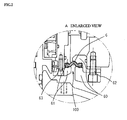
- Fig. 2 is an enlarged view of a position where the sealing member is disposed ("A" in Fig. 1 ).
- Fig. 3 is a perspective view of the sealing member and
- Fig. 4 is a cross sectional view of the sealing member.
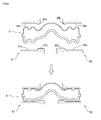
- Fig. 5 schematically illustrates the sealing member, which is clamped.
- a sealing member 6 is disposed so as to seal a gap 100 between the casing 3 and the connection portion 21c.
- the gap 100 is for example around about 100 mm. More particularly, the sealing member 6 is disposed so as to fill the gap 100 between the casing 3 and the connection portion 21c.
- An inner circumferential region (clamped portion) of the sealing member 6 is entirely fixed by the clamping means of the connection portion 21 c, while an outer circumferential region (clamped portion) is entirely fixed by the clamping means of the casing 3.
- Fig. 2 shows an exemplary configuration of the clamping means in which the sealing member 6 is sandwiched by rigid members (e.g.
- each of 6 bolts exerts the tightening torque of 8.6 Nm as the tightening pressure, but the tightening pressure may be varied depending on materials of the sealing member 6 and the operational condition of the apparatus.
- the sealing member 6 has a circular ring shape.
- the sealing member 6 may be properly dimensioned depending on the size of the apparatus on which the member 6 is mounted.
- the sealing member 6 may have an inner diameter of about 290 mm, an outer diameter of about 350 mm and a thickness of about 6 mm.
- the shape is not limited to the circle and the various shapes such as a rectangle and an elliptic may be employed. That is, depending on the shape of the opening of the casing 3 and/or the connection portion 21c, the shape of the sealing member 6 may properly defined.
- an upwardly curved convex portion 64 is formed in the center of the sealing member 6.
- Regions (clamped portion) 65 and 66 which are clamped respectively by the clamping means of the casing 3 and the clamping means of the connection portion 21, are respectively formed on both sides of the central convex portion (i.e., both the inner and outer circumferential sides).
- the central convex portion 64 of the sealing member 6 is disposed in a gap between the casing 3 and the connection portion 21c.
- a radius (R) of the convex portion may be set to be 6 mm on the outer circumferential side and 2 mm on the inner circumferential side.
- the regions 65 and 66 (clamped portions) on opposing ends of the sealing member 6 have two ridges 65a, 65b and two ridges 66a, 66b, respectively.
- the ridges 65a and 65b are separated from each other in a radial direction and likewise the ridges 66a and 66b are separated.
- Each of the ridges 65a, 65b, 66a and 66b are preferably formed in a ring shape around the entire sealing member 6 (see Fig. 3 ).
- the sealing member 6 comprising an incompressible elastic material generates the repulsive force against the compression force and the repulsive force is proportional to the contact area.
- the clamped portions 65 and 66 are planer or substantially planer, since the compression force due to tightening the fixing means is dispersed, the higher tightening torque may be required in order to obtain the required surface pressure.
- the clamped portion has a single ridge, the contact area with the clamping means is smaller than the planer clamped portion and the greater repulsive force is generated from the lower compression force. Therefore, the greater sealing property is obtained.
- the spaces between the ridges act as an intermediate volume and therefore the sealed state can be maintained even when the displacement of the mounting position occurs.
- the two-ridge configuration allows the sealed state to be maintained in a stable manner.
- the sealing member 6 can provide the greater sealing property at the lower compression force, the tightening torque can be set to be lower.
- it becomes possible to downsize of the sealing member 6 i.e., to set the width of the clamped portions 65 and 66 to be reduced). It is preferable to form two-ridge configuration of 65a, 65b and 66a, 66b in view of, for example the manufacturing cost of the sealing member 6.
- more than two ridges may be employed.
- the ridges 65a, 65b and 66a, 66b are preferably formed on both upperside and underside surfaces of the clamped portions 65 and 66, respectively.
- the height and width of the ridges 65a, 65b and 66a, 66b are not particularly limited, but the height is preferably set to correspond to the squeezing margins when being clamped.
- the height of the ridges 65a, 65b and 66a, 66b i.e., the squeezing margin L1 may be set to 2 mm.
- the sealing member 6 has a three-layer structure including a lower layer 67 made of a fluorine-base resin, an intermediate layer 68 made of a rubber-base resin, and a base fabric (i.e., upper layer) 69 made of a nylon-base material. These members 67, 68 and 69 of the three-layer structure are not preferably deposited simply as three separated members. In a manufacturing process of the sealing member 6, the members 67, 68 and 69 are preferably integrated such as by an adhesive or welding. However, the adhering means is not limited thereto.
- a polytetrafluoroethylene (PTFE) etc. may be used for the fluorine-base resin.
- the material of the lower layer 67 is preferably selected from materials which have the corrosion resistance to the internal atmosphere within the casing 3 (i.e., to objects to be processed by the apparatus).
- a fluororubber preferably FKM such as VITON®
- a nitrile butadiene rubber (NBR) etc. may be used.
- the nylon-base material constituting the base fabric (cloth-like member) 69 for example a nylon 6, a polypropylene etc. may be used.
- each thickness of the layers 67, 68 and 69 may be set adequately.
- the lower layer 67 made of the fluorine-base resin may be 0.8 mm thick
- the intermediate layer 68 made of the rubber-base resin may be 3 mm thick
- the base fabric (i.e., the upper layer) made of the nylon-base material may be 0.3 mm thick.
- each of clamping means have planer opposing surfaces 60a and 61a which sandwich the clamped portions 65 and 66 respectively.
- the surfaces 60a and 61b have preferably ridges 60b and 61b respectively, which engage the respective skirt portions of the ridges 65b and 66b inner side of the sealing member 6.
- the ridges 65b and 66b of the sealing member 6 are also preferably formed entirely around both of the inner circumference of the casing 3 and the outer circumference of the connection portion.
- the metal members 60 and 61 as clamping means sandwich the opposing clamped portion 65 and 66 respectively and further compress them at the predetermined tightening torque by means of the fastening means (reference numerals 62 and 63 in Fig. 2 ) such as the bolt etc. to deform (squeeze) the respective two ridges 65a, 65b and 66a, 66b of the clamped portions 65 and 66.
- the fastening means reference numerals 62 and 63 in Fig. 2
- the bolt etc. such as the bolt etc.
- the sealing member 6 since the respective two ridges 65a, 65b and 66a, 66b with the heights corresponding to the squeezing margins are contact with the respective planer surfaces 60a and 61a of the clamping means and deformed relative to the surfaces, the surface pressure may be reduced accordingly.
- Fig. 5 schematically illustrates such deformation and the deformation is not necessarily limited to the deformation as illustrated. However, once the ridges and valleys are completely collapsed, the space acting as the intermediate volume is eliminated and it becomes impossible to deal with any displacement of the mounting position.
- the clamping means have the respective ridges 60b and 61b which protrude to engage the respective skirt portions of the ridges 65b and 66b inner side of the sealing member 6 so as to conform the sealing member 6, it is ensured that the downsized sealing member 6 whose width becomes smaller is certainly clamped, thereby ensuring the sealing property.
- the novel sealing member 6 is employed which has the three-layer structure in which the lower layer 67 made of the fluorine-base resin, the intermediate layer 68 made of the rubber-base resin, and the base fabric (i.e., upper layer) 69 made of the nylon-base material, and the cross sectional shape of which has a convexly curved central portion 64 and the opposing clamped portions 65 and 66 on both sides of the central portion, each of the clamped portions having the respective two ridges 65a, 65b and 66a, 66b. Therefore, the whole contact area with the clamped means is reduced and the required surface pressure is ensured through less tightening pressures. Therefore, the tight clamping can be realized.
- the spaces between the ridges act as the intermediate volume, thereby allowing to deal with any displacement of the mounting position.
- the sealing member 6 consistent with this embodiment, it becomes possible to ensure and maintain the sealed state between the connection portion 21c and the casing 3.
- the inventors have confirmed that the long term operation (over a year) may be achieved under the high-pressure operation condition (the operation pressure of 0.6 MPa).
- the central convex portions particularly can absorb such eccentric movement and the clamped portions are tightly clamped, thereby the degradation of the sealing property can be suppressed.
- the eccentric movement is likely to occur in case that the bowl 2 is suspendedly supported as the vertical decanter 1. Therefore, this embodiment is particularly effective in the above configuration.
- the employment of the sealing member 6 in which the three layers, i.e. the lower layer 67 made of the fluorine-base resin, the intermediate layer 68 made of the rubber-base resin, and the base fabric (i.e., upper layer) 69 made of nylon-base material, are integrated can enhance the sealing property and facilitates to mount the sealing member on the apparatus.
- the sealing member 6 in the described configuration has an advantage that the strength of the sealing member 6 can be adjusted itself by selecting the material of the base fabric 69.
- the sealing property can be ensured even if the tightening torque is set to be lowered, the mounting failure, looseness of the bolt etc. are not likely to occur, and the mounting work on the apparatus becomes easier.
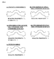
- the inventors confirmed the sealing properties not only for a sealing member (a) as described above the sealing member 6, and also for a sealing member (b) with two ridges on only the upperside surface, a sealing member (c) with two ridges, one on the upperside surface and another on the underside surface, and a sealing member (d) with two ridges on only the underside surface, and the sealing member (e) with no ridge.
- Fig. 6 shows the all results for the sealing member (a) to (e).
- the sealing member (a) had the good sealing property based on the contact area (the sealing property: o), and the leakage due to any displacement of the mounting position by the vibrations etc. did not occur (the stability: o).
- the sealing property was good (o), while the leakage due to the displacement of the mounting position was recognized (the stability: ⁇ ).
- the rubber since the rubber is also viscoelastic, it deforms plastically due to the stress-relaxation under pressure, and deforms plastically due to the creep under deformation. Since the plastic deformation causes the surface pressure to seal the contacting portion to reduce, the plastic deformation is desirably suppressed. For this end, any material and shape that keep the initial surface pressure over long time period are desirable.
- the described sealing member (a) has the respective two ridges and the surface pressure for the sealing applies on part of the clamped portion by compressing the top portion of the ridges. Therefore, while maintaining the sealed surface pressure, the whole tightening pressure is set to be reduced. In addition, since the distortion due to the deformation is transferred to the valley-like portion of the ridges, the plastic deformation which may cause disadvantages against the long term durability can be reduced. On the other hand, in case that the single ridge, since there is not the valley-like portion, the tightening pressure increases and the plastic deformation becomes larger, thus it is not desirable in the durability. Therefore, although the sealing members (b)-(d) with ridges have each advantage, it is not superior to that of the sealing member (a).
Landscapes
- Centrifugal Separators (AREA)
- Gasket Seals (AREA)
- Sealing Devices (AREA)
Description
- The present invention relates to a rotation processing apparatus such as a centrifugal separator etc.
- A decanter type centrifugal separator, for example disclosed in
Patent Literature 1 listed below is a rotation processing apparatus which performs a separation operation by applying a centrifuge force to a solution to be processed. The centrifuge separator has a bowl serving as a rotatable body and a screw conveyer, which are disposed in a casing, and a drive mechanism (e.g., a drive motor) for rotating the bowl which is disposed outside of the casing. A power from the drive motor is transmitted to the screw conveyer via a gear box serving as a differential rate generator, and the screw conveyer rotates with a differential rate relative to the rotation rate of the bowl. A shaft serving as a rotary shaft for the bowl is rotatably supported to a connection portion extending through an opening of the casing. In this configuration, the power from the drive motor is transmitted to an end of the shaft extending to out of the casing. The connection portion includes a bearing mechanism such as a bearing and a sealing mechanism such as a gland packing. - The casing has a hermetic sealing structure so that any impurities are not added. In particular, in case that an object to be processed involves chemicals, foods, or the like, the hermetic in the casing as possible must be maintained in order to prevent the addition of the impurities into the casing and/or the leakage of the chemicals etc. from the casing. For this purpose, a mechanical seal with the improved sealing property is reported also in Japanese Patent Laid-Open No.
2012-7634 JP2012007634 A Patent Literature 1 may be applied to a gear box. On the other hand, as a sealing mechanism which seals a gap between the opening of the casing and the connection portion, a planer ring-shaped sealing member made of any resin material is generally used. An inner circumferential region (clamped portion) of the sealing member is clamped by the clamping means (compression means) of the connection portion, while an outer circumferential region (clamped portion) is clamped by the clamping means (compression means) of the casing. The clamping means is required to clamp the sealing member at the required pressure depending on an internal pressure of the casing. In general, the clamping means has a structure to fasten for example by a bolt or screw mechanism and a bolt or the like is fastened at the required torque. - However, there is a problem that the sealing member which seals the gap between the opening of the casing and the connection portion does not always have a sufficient sealing property. In particular, the leakage due to withstand pressure failure may occur in operational condition under which the pressure is set to be high (for example, equal to or greater than 0.6 MPa). Furthermore, in an apparatus with a rotatable body, since the rotatable body moves eccentrically relative to a casing during rotating, the clamping means for compressing the clamped portion of the sealing member may be loosened, resulting in the degradation of the sealing property. For the vertical decanter such as disclosed in the
Patent Literature 1, since the bowl serving as the rotatable body is suspendedly supported, any shakes (vibrations) which occurs during its rotational movement is likely to cause the degradation of the sealing property. - Moreover, the conventional sealing member has problems that the higher surface pressure on the surface to be clamped is required, thus a higher clamping torque is required to clamp the bolt or the like. In the case of the surface pressure on the surface to be clamped is higher, the mounting failure of the sealing means and loosening the bolt etc. are likely to occur, and mounting the sealing member on the apparatus is not easy.
- The present invention is made to solve the problems described simply as examples, the object of the invention is to provide a technique which can improve the sealing property of a ring-shaped sealing member when a gap between an opening of a casing serving as a pressure vessel and a connection portion of a rotation processing mechanism which extends through the opening is sealed by means of the sealing member.
- Another object of the present invention is to provide a technique which can suppress the degradation of the sealing property of the sealing member due to the rotational movement of the rotatable body.
- The still another object of the present invention is to provide a technique which facilitates to mount the sealing member on the apparatus.
-
- (1) A rotation processing apparatus according to the present invention comprises: a casing serving as a pressure vessel; a rotation processing mechanism including a rotatable body rotating in the casing, a drive unit which is disposed outside of the casing and rotates the rotatable body, and a connection portion which extends through an opening of the casing and connects the rotatable body and the drive unit; and a ring-shaped sealing member for sealing a gap between the opening of the casing and the connection portion disposed in the opening. The rotation processing apparatus is characterized in that the sealing member has a three-layer structure in which a layer of a fluorine-base resin material, a layer of a rubber-base resin material and a base fabric of a nylon-base material are deposited in that order from a side that is in contact with an internal atmosphere within the casing, and a cross sectional shape of the sealing member has a convexly curved center portion disposed in the gap between the casing and the connection portion and clamped portions on both sides of the central portion, each of the clamped portions has at least two ridges to be clamped by clamping means of the casing and clamping means of the connection portion.
- (2) The at least two ridges are formed on both upperside and underside surfaces of the sealing member.
- (3) The opening is formed on an upper portion of the casing, the rotatable body is suspendedly supported by the connection portion.
- (4) The rotatable body includes a rotation bowl for separating a solid and a liquid by the action of centrifugal force and a screw conveyer, and the rotation processing apparatus is a decanter type centrifugal separator.
- The rotation processing apparatus of the present invention employs the sealing member which has a three-layer structure in which a layer of a fluorine-base resin material, a layer of a rubber-base resin material and a base fabric of a nylon-base material are deposited in that order from a side that is in contact with an internal atmosphere within the casing and the cross sectional shape of the sealing member is designed to have a convexly curved center portion and the opposing portions on both side of the central portion. Each of opposing portions has at least two ridges to be clamped by clamping means of both of the casing and the connection portion. This allows the sealing property if the opening of the casing in which the connection portion of the rotation processing mechanism is disposed to be improved, as well as allows to suppress the degradation of the sealing property due to any shakes (vibrations) which may occur during the rotational movement of the rotatable body.
- Therefore, the rotation processing apparatus according to the present invention can be applied to a chemical-, food-, or biological-related technical field in which it is desired to avoid the addition of impurities. The rotation processing apparatus also can be adapted to the operational condition under which the pressure within the casing is set to be high, and allows to realize the safe operation in which the leakage of the contents is suppressed.
- Furthermore, the rotation processing apparatus according to the present invention can be reduced the surface pressure at the clamped portions compressed by the clamping means because the sealing member with the previously described configuration is employed. This reduces the occurrence of the mounting failure of the sealing member and looseness of the bolt etc. of the clamping means, and facilitates to mount the sealing member on the apparatus. Moreover, the diameter of the sealing member can be lessened, resulting to facilitate to mounting the sealing member on the apparatus.
-
-
Fig. 1 shows the configuration of a decanter according to a preferred embodiment of the present invention, -
Fig. 2 shows a mounting position for a sealing member employed in the decanter inFig. 1 , -
Fig. 3 is a perspective view of the sealing member -
Fig. 4 is a cross sectional view of the sealing member, -
Fig. 5 schematically illustrates the sealing member, which is clamped, and -
Fig. 6 shows results of examples to confirm the effect of the present invention. - As a rotation processing apparatus according to the preferred embodiment of the present invention, an exemplary decanter type centrifuge separator will be described. It should be noted, however, that the technical scope of this invention should not be interpreted without any limitation through the embodiment described below.
-
Fig. 1 shows the whole structure of a centrifuge separator according to the present embodiment. Avertical decanter 1 is illustrated as an example of the centrifuge separator. Thedecanter 1 comprises abowl 2 serving as a rotatable body. Thebowl 2 is a generally cylindrical rotatable body into which a solution to be processed is supplied, and the centrifuge force to separate a solid from the liquid is applied to the solution to be processed. Thebowl 2 is disposed within acasing 3 serving as an exterior casing and configured to be rotatable about a vertical axis by means of adrive motor 31 as a drive unit which is disposed outside of thecasing 3. - A
disk member 21 referred to as a front hub is disposed on an upper portion of thebowl 2 and an outlet (separated liquids outlet) 21a through which separated liquids are discharged is formed on thedisk member 21. On the other hand, on a lower portion of thebowl 2, an outlet (solids outlet) 22 is formed through which the separated solids are discharged. Also, ashaft 21b serving as a rotary shaft for thebowl 2 is rotatably supported to aconnection portion 21 c extending through the opening at the upper portion of thecasing 3. In this configuration, a power fromdrive motor 31 is transmitted to an end of theshaft 21b extending to out of thecasing 3. Abearing mechanism 21d such as a bearing and a rotaryshaft sealing mechanism 21e such as a gland packing are disposed within theconnection portion 21c. The driving force from thedrive motor 31 is transmitted, for example via an endlessrotary belt 33 crosslinked to apulley 32, to apulley 34 on the side of thebowl 2. However, the driving force transmission scheme is not limited to this configuration. In this embodiment, a rotation processing mechanism is comprised of thebowl 2, theconnection portion 21c and thedrive motor 31, however, the mechanism is not limited to these structures. - A
screw conveyer 4 for conveying the solids to thesolids outlet 22 is disposed within thebowl 2. Thescrew conveyer 4 rotates with a differential rate relative to the rotation rate of thebowl 2 and conveys the solids to thesolids outlet 22 by a spirally formedscrew vane 41. Thus, thebowl 2 and thescrew conveyer 4 are connected to agear box 5 serving as a differential rate generator, and once thebowl 2 is rotated by means of thedrive motor 31, its rotation rate is changed through thegear box 5, thereby thescrew conveyer 4 rotates with the differential rate relative to the rotation rate of thebowl 2. On the other hand, the solution to be processed is continuously supplied into thebowl 2 through thesupply nozzle 23, thereby the separated liquids after the solids have been separated are discharged (so called, overflowed) out of theoutlet 21a. The separated liquids discharged out of thebowl 2 are supplied to a gutter-likeliquid receiving portion 35 disposed on the inner circumferential surface of thecasing 3, and subsequently discharged, through thedischarge nozzle 36 in communication with theliquid receiving portion 35, to outside of the apparatus. - The lower side of the
bowl 2 and thescrew conveyer 4 is open and atip 23a of thesupply nozzle 23 is inserted through the opening with thesupply nozzle 23 being not contact with therotating bowl 2 and screwconveyer 4. Once the solution to be processed is supplied to a cavity (buffer) formed within thescrew conveyer 4, the solution to be processed is fed within thebowl 2 through theliquid discharging port 42 formed on a trunk of thescrew conveyer 4 by the action of the centrifuge force. In addition, thetip 23a of thesupply nozzle 23 is formed in a double-tube configuration and the outer tube is communication with a rinseliquid supply nozzle 24. The rinse liquids can be supplied into thebowl 2 in order to wash away the separated solids, for example. However, the rinse liquids may not be necessarily required. - As previously described, the
screw conveyer 4 rotates with the differential rate relative to the rotation rate of thebowl 2. The phrase "rotating with the differential rate relative to the rotation rate of thebowl 2" involves not only rotating slower than the rotation rate of thebowl 2, but also rotating higher than that of thebowl 2. The method for generating such differential rate includes designing a gear ratio of thegear box 5 to generate the desired differential rate, disposing a back drive motor to apply a braking torque to thescrew conveyer 4, for example. Thedecanter 1 illustrated inFig. 1 generates the differential rate only by the gear ratio of thegear box 5 without using the back drive motor. Thegear box 5 is known for example as disclosed thePatent Literature 1 etc., and accordingly will not be described herein in detail. - Now, a sealing member according to the present embodiment will be described with reference to
Figs. 2 to 5 .Fig. 2 is an enlarged view of a position where the sealing member is disposed ("A" inFig. 1 ).Fig. 3 is a perspective view of the sealing member andFig. 4 is a cross sectional view of the sealing member.Fig. 5 schematically illustrates the sealing member, which is clamped. - As shown in
Fig. 2 , a sealingmember 6 is disposed so as to seal agap 100 between thecasing 3 and theconnection portion 21c. Thegap 100 is for example around about 100 mm. More particularly, the sealingmember 6 is disposed so as to fill thegap 100 between thecasing 3 and theconnection portion 21c. An inner circumferential region (clamped portion) of the sealingmember 6 is entirely fixed by the clamping means of theconnection portion 21 c, while an outer circumferential region (clamped portion) is entirely fixed by the clamping means of thecasing 3.Fig. 2 shows an exemplary configuration of the clamping means in which the sealingmember 6 is sandwiched by rigid members (e.g. metal ring members) 60 and 61, and the tightening pressure is applied by tighteningmembers member 6. As an example, each of 6 bolts exerts the tightening torque of 8.6 Nm as the tightening pressure, but the tightening pressure may be varied depending on materials of the sealingmember 6 and the operational condition of the apparatus. - With regard to its shape etc. of the sealing
member 6 will be described in more detail. As shown inFig. 3 , the sealingmember 6 has a circular ring shape. The sealingmember 6 may be properly dimensioned depending on the size of the apparatus on which themember 6 is mounted. As an example, the sealingmember 6 may have an inner diameter of about 290 mm, an outer diameter of about 350 mm and a thickness of about 6 mm. Furthermore, the shape is not limited to the circle and the various shapes such as a rectangle and an elliptic may be employed. That is, depending on the shape of the opening of thecasing 3 and/or theconnection portion 21c, the shape of the sealingmember 6 may properly defined. - With regard to a cross sectional shape of the sealing member 6 (taken along line B-B of
Fig. 3 ), as shown inFig. 4 , an upwardly curvedconvex portion 64 is formed in the center of the sealingmember 6. Regions (clamped portion) 65 and 66, which are clamped respectively by the clamping means of thecasing 3 and the clamping means of theconnection portion 21, are respectively formed on both sides of the central convex portion (i.e., both the inner and outer circumferential sides). The centralconvex portion 64 of the sealingmember 6 is disposed in a gap between thecasing 3 and theconnection portion 21c. Thus, as rotating thebowl 2, even if theconnection portion 21c moves eccentrically due to any shakes for example, the deformation of theconvex portion 64 can absorb the eccentric movement. As an example, a radius (R) of the convex portion may be set to be 6 mm on the outer circumferential side and 2 mm on the inner circumferential side. - The
regions 65 and 66 (clamped portions) on opposing ends of the sealingmember 6 have tworidges ridges ridges ridges ridges Fig. 3 ). Herein, the sealingmember 6 comprising an incompressible elastic material generates the repulsive force against the compression force and the repulsive force is proportional to the contact area. Therefore, in case that the clampedportions casing 3 are partitioned only by a line contact of the single ridge, it is difficult to keep up with the displacement of the mounting position which may be caused by any vibration transmission and the rapid reduce the pressure of the casing, and therefore the stable sealing property cannot be obtained. In contrast, in the case that the respective clamped portions has tworidges member 6 can provide the greater sealing property at the lower compression force, the tightening torque can be set to be lower. Moreover, it becomes possible to downsize of the sealing member 6 (i.e., to set the width of the clampedportions member 6. However, more than two ridges may be employed. - The
ridges portions ridges ridges - The sealing
member 6 has a three-layer structure including alower layer 67 made of a fluorine-base resin, anintermediate layer 68 made of a rubber-base resin, and a base fabric (i.e., upper layer) 69 made of a nylon-base material. Thesemembers member 6, themembers - In this embodiment, for example a polytetrafluoroethylene (PTFE) etc. may be used for the fluorine-base resin. Since the
lower layer 67 is also contact with an internal atmosphere within thecasing 3, the material of thelower layer 67 is preferably selected from materials which have the corrosion resistance to the internal atmosphere within the casing 3 (i.e., to objects to be processed by the apparatus). For the rubber-base resin of theintermediate layer 68, for example a fluororubber (preferably FKM such as VITON®), a nitrile butadiene rubber (NBR) etc. may be used. For the nylon-base material constituting the base fabric (cloth-like member) 69, for example anylon 6, a polypropylene etc. may be used. - The each thickness of the
layers lower layer 67 made of the fluorine-base resin may be 0.8 mm thick, theintermediate layer 68 made of the rubber-base resin may be 3 mm thick, and the base fabric (i.e., the upper layer) made of the nylon-base material may be 0.3 mm thick. - On the other hand, each of clamping means have
planer opposing surfaces portions surfaces ridges ridges member 6. Likewise theridges member 6, theridges casing 3 and the outer circumference of the connection portion. - As schematically illustrated in
Fig. 5 , in the sealingmember 6 configured as described above, themetal members portion reference numerals Fig. 2 ) such as the bolt etc. to deform (squeeze) the respective tworidges portions member 6 according to this embodiment, since the respective tworidges respective planer surfaces Fig. 5 schematically illustrates such deformation and the deformation is not necessarily limited to the deformation as illustrated. However, once the ridges and valleys are completely collapsed, the space acting as the intermediate volume is eliminated and it becomes impossible to deal with any displacement of the mounting position. Moreover, since the clamping means have therespective ridges ridges member 6 so as to conform the sealingmember 6, it is ensured that the downsized sealingmember 6 whose width becomes smaller is certainly clamped, thereby ensuring the sealing property. - As previously described, according to the
decanter 1 consistent with the described embodiment, thenovel sealing member 6 is employed which has the three-layer structure in which thelower layer 67 made of the fluorine-base resin, theintermediate layer 68 made of the rubber-base resin, and the base fabric (i.e., upper layer) 69 made of the nylon-base material, and the cross sectional shape of which has a convexly curvedcentral portion 64 and the opposing clampedportions ridges member 6 consistent with this embodiment, it becomes possible to ensure and maintain the sealed state between theconnection portion 21c and thecasing 3. The inventors have confirmed that the long term operation (over a year) may be achieved under the high-pressure operation condition (the operation pressure of 0.6 MPa). - Further, according to the described embodiment, even if the
bowl 2 moves eccentrically due to any shakes (vibrations) which occur during the rotational movement of thebowl 2, the central convex portions particularly can absorb such eccentric movement and the clamped portions are tightly clamped, thereby the degradation of the sealing property can be suppressed. The eccentric movement is likely to occur in case that thebowl 2 is suspendedly supported as thevertical decanter 1. Therefore, this embodiment is particularly effective in the above configuration. - Still further, according to the described embodiment, the employment of the sealing
member 6 in which the three layers, i.e. thelower layer 67 made of the fluorine-base resin, theintermediate layer 68 made of the rubber-base resin, and the base fabric (i.e., upper layer) 69 made of nylon-base material, are integrated can enhance the sealing property and facilitates to mount the sealing member on the apparatus. In addition, the sealingmember 6 in the described configuration has an advantage that the strength of the sealingmember 6 can be adjusted itself by selecting the material of thebase fabric 69. - Still further, according to the described embodiment, since the sealing property can be ensured even if the tightening torque is set to be lowered, the mounting failure, looseness of the bolt etc. are not likely to occur, and the mounting work on the apparatus becomes easier.
- Now, the results of the test which was performed to confirm the effect of this invention are described below.
- The inventors confirmed the sealing properties not only for a sealing member (a) as described above the sealing
member 6, and also for a sealing member (b) with two ridges on only the upperside surface, a sealing member (c) with two ridges, one on the upperside surface and another on the underside surface, and a sealing member (d) with two ridges on only the underside surface, and the sealing member (e) with no ridge.Fig. 6 shows the all results for the sealing member (a) to (e). - Because of the reasons described previously, the sealing member (a) had the good sealing property based on the contact area (the sealing property: o), and the leakage due to any displacement of the mounting position by the vibrations etc. did not occur (the stability: o). On the other hand, in the sealing member (c) with one ridge for each of the upperside and underside surfaces, the sealing property was good (o), while the leakage due to the displacement of the mounting position was recognized (the stability: ×). In the planer sealing member (e) with no ridge and the sealing members (b) and (d) whose either upperside or underside surface was planer, the compression force was dispersed, since the contact area was large, so that the required surface pressure was not able to ensure at the same tightening torque as that of the sealing member (a) (the sealing property: ×).
- With consideration to the results, assume that since the rubber is also viscoelastic, it deforms plastically due to the stress-relaxation under pressure, and deforms plastically due to the creep under deformation. Since the plastic deformation causes the surface pressure to seal the contacting portion to reduce, the plastic deformation is desirably suppressed. For this end, any material and shape that keep the initial surface pressure over long time period are desirable.
- The described sealing member (a) has the respective two ridges and the surface pressure for the sealing applies on part of the clamped portion by compressing the top portion of the ridges. Therefore, while maintaining the sealed surface pressure, the whole tightening pressure is set to be reduced. In addition, since the distortion due to the deformation is transferred to the valley-like portion of the ridges, the plastic deformation which may cause disadvantages against the long term durability can be reduced. On the other hand, in case that the single ridge, since there is not the valley-like portion, the tightening pressure increases and the plastic deformation becomes larger, thus it is not desirable in the durability. Therefore, although the sealing members (b)-(d) with ridges have each advantage, it is not superior to that of the sealing member (a).
- While the present invention has been described in detail in conjunction with specific embodiments, it is apparent to persons of ordinary knowledge in this technological field that various substitutions, modifications, changes, and the like to the forms and details can be made without departing from the spirit and scope of the invention that are defined in the description of claims. Therefore, the scope of the invention is not limited to the above-described embodiments and the accompanying drawings but defined by the claims.
- 1
decanter 2bowl 21b shaftc c connection portion 3casing 31drive motor 4screw conveyer 5gear box 6 sealingmember 64 centralconvex portion 65 clampedportion 66 clampedportion 67 lower layer made of a fluorine-base resin 68 intermediate layer made of a rubber-base resin 69 base fabric (i.e., upper layer) 69 made of a nylon-base material
Claims (4)
- A rotation processing apparatus, comprising:a casing (3) serving as a pressure vessel;a rotation processing mechanism including a rotatable body (4) rotating in the casing, a drive unit which is disposed outside of the casing and rotates the rotatable body, and a connection portion which extends through an opening of the casing and connects the rotatable body and the drive unit; anda ring-shaped sealing member (6) for sealing a gap between the opening of the casing and the connection portion disposed in the opening, the rotation processing apparatus characterized in that the sealing member has a three-layer structure in which a layer (67) of a fluorine-base resin material, a layer of a rubber-base resin material and a base fabric (69) of a nylon-base material are deposited in that order from a side that is in contact with an internal atmosphere within the casing, anda cross sectional shape of the sealing member has a convexly curved center portion (64) disposed in the gap between the casing and the connection portion and clamped portions on both sides of the central portion, each of the clamped portions having at least two ridges (65, 65b; 66a, 66b) to be clamped by clamping means of the casing and clamping means of the connection portion.
- The rotation processing apparatus according to claim 1, characterized in that the at least two ridges are formed on both upperside and underside surfaces of the sealing member.
- The rotation processing apparatus according to claim 1 or 2, characterized in that the opening is formed on an upper portion of the casing, the rotatable body is suspendedly supported by the connection portion.
- The rotation processing apparatus according to any of claims 1 to 3, characterized in that the rotatable body includes a rotation bowl for separating a solid and a liquid by the action of centrifugal force and a screw conveyer, and the rotation processing apparatus is a decanter type centrifugal separator.
Applications Claiming Priority (1)
| Application Number | Priority Date | Filing Date | Title |
|---|---|---|---|
| JP2012131796A JP5048165B1 (en) | 2012-06-11 | 2012-06-11 | Rotation processing device seal mechanism |
Publications (2)
| Publication Number | Publication Date |
|---|---|
| EP2674647A1 EP2674647A1 (en) | 2013-12-18 |
| EP2674647B1 true EP2674647B1 (en) | 2014-07-23 |
Family
ID=47189439
Family Applications (1)
| Application Number | Title | Priority Date | Filing Date |
|---|---|---|---|
| EP20120199634 Not-in-force EP2674647B1 (en) | 2012-06-11 | 2012-12-28 | Sealing mechanism of a rotation processing apparatus |
Country Status (3)
| Country | Link |
|---|---|
| EP (1) | EP2674647B1 (en) |
| JP (1) | JP5048165B1 (en) |
| CN (1) | CN103486271B (en) |
Families Citing this family (5)
| Publication number | Priority date | Publication date | Assignee | Title |
|---|---|---|---|---|
| JP5547331B1 (en) | 2013-11-04 | 2014-07-09 | 巴工業株式会社 | Centrifuge |
| CN109046797A (en) * | 2018-10-18 | 2018-12-21 | 张家港市蓝鸟机械有限公司 | A kind of small-sized decanter centrifuge of vertical and high-speed |
| CN111609079B (en) * | 2020-05-28 | 2022-07-12 | 中国电子工程设计院有限公司 | Vibration isolation sealing system |
| CN111609138A (en) * | 2020-05-28 | 2020-09-01 | 中国电子工程设计院有限公司 | Sealed Vibration Isolation Device and Sealed Vibration Isolation Connection Equipment |
| CN111609137B (en) * | 2020-05-28 | 2022-07-12 | 中国电子工程设计院有限公司 | Flexible sealing device |
Family Cites Families (15)
| Publication number | Priority date | Publication date | Assignee | Title |
|---|---|---|---|---|
| GB986217A (en) * | 1963-02-06 | 1965-03-17 | Crane Packing Ltd | Bellows |
| US3565330A (en) * | 1968-07-11 | 1971-02-23 | Cryogenic Technology Inc | Rotary seal and centrifuge incorporating same |
| JPS4719976Y1 (en) * | 1970-11-20 | 1972-07-06 | ||
| JPS5031669Y2 (en) * | 1971-02-05 | 1975-09-16 | ||
| JPS5139879U (en) * | 1974-09-20 | 1976-03-25 | ||
| JPS55163054U (en) * | 1979-05-14 | 1980-11-22 | ||
| US5145191A (en) * | 1991-04-10 | 1992-09-08 | International Sales & Engineering, Inc. | Heat-resistant protective cover for a drive axle joint seal |
| US5340121A (en) * | 1992-10-15 | 1994-08-23 | Furon Company | Face seal with integral fluorocarbon polymer bellows |
| FR2706216B1 (en) * | 1993-06-07 | 1995-07-21 | Robatel Slpi | Continuous decanter for processing nuclear products. |
| JP3006027U (en) * | 1994-06-30 | 1995-01-17 | 三菱化工機株式会社 | Centrifuge seal packing |
| JP3336291B2 (en) * | 1999-05-21 | 2002-10-21 | 巴工業株式会社 | Decanter centrifuge |
| US7270787B2 (en) * | 2003-07-31 | 2007-09-18 | Thermo Fisher Scientific (Asheville) Llc | Centrifuge sample jar and closure |
| US7670276B2 (en) * | 2005-08-26 | 2010-03-02 | Tomoe Engineering Co., Ltd. | Decanter type centrifugal separator with torque transmission mechanism |
| US7708285B2 (en) * | 2005-10-21 | 2010-05-04 | A.W. Chesterton Company | Elastomer spring mechanical seal |
| JP2012007634A (en) | 2010-06-22 | 2012-01-12 | Tomoe Engineering Co Ltd | Mechanical seal, finishing method of mechanical seal and gear box for centrifugal separator |
-
2012
- 2012-06-11 JP JP2012131796A patent/JP5048165B1/en active Active
- 2012-12-28 EP EP20120199634 patent/EP2674647B1/en not_active Not-in-force
-
2013
- 2013-02-06 CN CN201310047274.1A patent/CN103486271B/en active Active
Also Published As
| Publication number | Publication date |
|---|---|
| CN103486271B (en) | 2016-03-09 |
| CN103486271A (en) | 2014-01-01 |
| EP2674647A1 (en) | 2013-12-18 |
| JP2013255870A (en) | 2013-12-26 |
| JP5048165B1 (en) | 2012-10-17 |
Similar Documents
| Publication | Publication Date | Title |
|---|---|---|
| EP2674647A1 (en) | Sealing mechanism of a rotation processing apparatus | |
| AU2005233534B2 (en) | Magnetically driven gear pump | |
| JP4564583B2 (en) | Horizontal centrifuge | |
| KR101803843B1 (en) | Water ring vacuum pump for component change type | |
| CN110817165B (en) | A polyurethane resin safety transport tank | |
| US8182252B2 (en) | Progressing cavity pump with split stator | |
| WO2015098467A1 (en) | Scroll fluid machine | |
| CA3070046A1 (en) | A rotary diaphragm positive displacement pump | |
| CA2473001A1 (en) | Stator for an eccentric screw pump or an eccentric worm motor operating on the moineau principle | |
| JP6150015B2 (en) | Sealing device | |
| CA2609025A1 (en) | Sanitary pump assembly | |
| MXPA05001683A (en) | A seal for sealing between components of a rotary machine. | |
| JP2012007634A (en) | Mechanical seal, finishing method of mechanical seal and gear box for centrifugal separator | |
| KR101827501B1 (en) | High vacuum and wear resistant double-cut rotary pump | |
| EP3655655B1 (en) | A rotary diaphragm positive displacement pump | |
| JP2012017761A (en) | Mechanical seal used for uniaxial eccentric screw pump and uniaxial eccentric screw pump | |
| CN117181458B (en) | Bag turning and discharging centrifugal machine | |
| US11255439B2 (en) | Axial shaft seal ring and seal arrangement | |
| EP3655657A1 (en) | A rotary diaphragm positive displacement pump | |
| JPS58180789A (en) | Pumping tube fixing device for squeeze system pump | |
| JP2544303Y2 (en) | Single shaft eccentric screw pump | |
| JP2011033081A (en) | Lip seal device and fluid machine using the same | |
| EP3655224A1 (en) | A rotary diaphragm positive displacement pump | |
| EP3655653B1 (en) | A rotary diaphragm positive displacement pump | |
| CN108857471A (en) | Five shaft platform of oil pressure cantilever and its design method |
Legal Events
| Date | Code | Title | Description |
|---|---|---|---|
| PUAI | Public reference made under article 153(3) epc to a published international application that has entered the european phase |
Free format text: ORIGINAL CODE: 0009012 |
|
| 17P | Request for examination filed |
Effective date: 20121228 |
|
| AK | Designated contracting states |
Kind code of ref document: A1 Designated state(s): AL AT BE BG CH CY CZ DE DK EE ES FI FR GB GR HR HU IE IS IT LI LT LU LV MC MK MT NL NO PL PT RO RS SE SI SK SM TR |
|
| AX | Request for extension of the european patent |
Extension state: BA ME |
|
| REG | Reference to a national code |
Ref country code: DE Ref legal event code: R079 Ref document number: 602012002521 Country of ref document: DE Free format text: PREVIOUS MAIN CLASS: F16J0015520000 Ipc: B04B0001200000 |
|
| GRAP | Despatch of communication of intention to grant a patent |
Free format text: ORIGINAL CODE: EPIDOSNIGR1 |
|
| RIC1 | Information provided on ipc code assigned before grant |
Ipc: F16J 15/52 20060101ALI20140218BHEP Ipc: B04B 1/20 20060101AFI20140218BHEP |
|
| INTG | Intention to grant announced |
Effective date: 20140313 |
|
| GRAS | Grant fee paid |
Free format text: ORIGINAL CODE: EPIDOSNIGR3 |
|
| GRAA | (expected) grant |
Free format text: ORIGINAL CODE: 0009210 |
|
| AK | Designated contracting states |
Kind code of ref document: B1 Designated state(s): AL AT BE BG CH CY CZ DE DK EE ES FI FR GB GR HR HU IE IS IT LI LT LU LV MC MK MT NL NO PL PT RO RS SE SI SK SM TR |
|
| REG | Reference to a national code |
Ref country code: GB Ref legal event code: FG4D |
|
| REG | Reference to a national code |
Ref country code: CH Ref legal event code: EP |
|
| REG | Reference to a national code |
Ref country code: IE Ref legal event code: FG4D |
|
| REG | Reference to a national code |
Ref country code: AT Ref legal event code: REF Ref document number: 678555 Country of ref document: AT Kind code of ref document: T Effective date: 20140815 |
|
| REG | Reference to a national code |
Ref country code: DE Ref legal event code: R096 Ref document number: 602012002521 Country of ref document: DE Effective date: 20140911 |
|
| REG | Reference to a national code |
Ref country code: AT Ref legal event code: MK05 Ref document number: 678555 Country of ref document: AT Kind code of ref document: T Effective date: 20140723 |
|
| REG | Reference to a national code |
Ref country code: NL Ref legal event code: VDEP Effective date: 20140723 |
|
| REG | Reference to a national code |
Ref country code: LT Ref legal event code: MG4D |
|
| PG25 | Lapsed in a contracting state [announced via postgrant information from national office to epo] |
Ref country code: FI Free format text: LAPSE BECAUSE OF FAILURE TO SUBMIT A TRANSLATION OF THE DESCRIPTION OR TO PAY THE FEE WITHIN THE PRESCRIBED TIME-LIMIT Effective date: 20140723 Ref country code: NO Free format text: LAPSE BECAUSE OF FAILURE TO SUBMIT A TRANSLATION OF THE DESCRIPTION OR TO PAY THE FEE WITHIN THE PRESCRIBED TIME-LIMIT Effective date: 20141023 Ref country code: GR Free format text: LAPSE BECAUSE OF FAILURE TO SUBMIT A TRANSLATION OF THE DESCRIPTION OR TO PAY THE FEE WITHIN THE PRESCRIBED TIME-LIMIT Effective date: 20141024 Ref country code: PT Free format text: LAPSE BECAUSE OF FAILURE TO SUBMIT A TRANSLATION OF THE DESCRIPTION OR TO PAY THE FEE WITHIN THE PRESCRIBED TIME-LIMIT Effective date: 20141124 Ref country code: LT Free format text: LAPSE BECAUSE OF FAILURE TO SUBMIT A TRANSLATION OF THE DESCRIPTION OR TO PAY THE FEE WITHIN THE PRESCRIBED TIME-LIMIT Effective date: 20140723 Ref country code: ES Free format text: LAPSE BECAUSE OF FAILURE TO SUBMIT A TRANSLATION OF THE DESCRIPTION OR TO PAY THE FEE WITHIN THE PRESCRIBED TIME-LIMIT Effective date: 20140723 Ref country code: SE Free format text: LAPSE BECAUSE OF FAILURE TO SUBMIT A TRANSLATION OF THE DESCRIPTION OR TO PAY THE FEE WITHIN THE PRESCRIBED TIME-LIMIT Effective date: 20140723 Ref country code: BG Free format text: LAPSE BECAUSE OF FAILURE TO SUBMIT A TRANSLATION OF THE DESCRIPTION OR TO PAY THE FEE WITHIN THE PRESCRIBED TIME-LIMIT Effective date: 20141023 |
|
| PG25 | Lapsed in a contracting state [announced via postgrant information from national office to epo] |
Ref country code: AT Free format text: LAPSE BECAUSE OF FAILURE TO SUBMIT A TRANSLATION OF THE DESCRIPTION OR TO PAY THE FEE WITHIN THE PRESCRIBED TIME-LIMIT Effective date: 20140723 Ref country code: HR Free format text: LAPSE BECAUSE OF FAILURE TO SUBMIT A TRANSLATION OF THE DESCRIPTION OR TO PAY THE FEE WITHIN THE PRESCRIBED TIME-LIMIT Effective date: 20140723 Ref country code: PL Free format text: LAPSE BECAUSE OF FAILURE TO SUBMIT A TRANSLATION OF THE DESCRIPTION OR TO PAY THE FEE WITHIN THE PRESCRIBED TIME-LIMIT Effective date: 20140723 Ref country code: LV Free format text: LAPSE BECAUSE OF FAILURE TO SUBMIT A TRANSLATION OF THE DESCRIPTION OR TO PAY THE FEE WITHIN THE PRESCRIBED TIME-LIMIT Effective date: 20140723 Ref country code: RS Free format text: LAPSE BECAUSE OF FAILURE TO SUBMIT A TRANSLATION OF THE DESCRIPTION OR TO PAY THE FEE WITHIN THE PRESCRIBED TIME-LIMIT Effective date: 20140723 Ref country code: NL Free format text: LAPSE BECAUSE OF FAILURE TO SUBMIT A TRANSLATION OF THE DESCRIPTION OR TO PAY THE FEE WITHIN THE PRESCRIBED TIME-LIMIT Effective date: 20140723 Ref country code: IS Free format text: LAPSE BECAUSE OF FAILURE TO SUBMIT A TRANSLATION OF THE DESCRIPTION OR TO PAY THE FEE WITHIN THE PRESCRIBED TIME-LIMIT Effective date: 20141123 Ref country code: CY Free format text: LAPSE BECAUSE OF FAILURE TO SUBMIT A TRANSLATION OF THE DESCRIPTION OR TO PAY THE FEE WITHIN THE PRESCRIBED TIME-LIMIT Effective date: 20140723 |
|
| REG | Reference to a national code |
Ref country code: DE Ref legal event code: R097 Ref document number: 602012002521 Country of ref document: DE |
|
| PG25 | Lapsed in a contracting state [announced via postgrant information from national office to epo] |
Ref country code: CZ Free format text: LAPSE BECAUSE OF FAILURE TO SUBMIT A TRANSLATION OF THE DESCRIPTION OR TO PAY THE FEE WITHIN THE PRESCRIBED TIME-LIMIT Effective date: 20140723 Ref country code: IT Free format text: LAPSE BECAUSE OF FAILURE TO SUBMIT A TRANSLATION OF THE DESCRIPTION OR TO PAY THE FEE WITHIN THE PRESCRIBED TIME-LIMIT Effective date: 20140723 Ref country code: RO Free format text: LAPSE BECAUSE OF FAILURE TO SUBMIT A TRANSLATION OF THE DESCRIPTION OR TO PAY THE FEE WITHIN THE PRESCRIBED TIME-LIMIT Effective date: 20140723 Ref country code: SK Free format text: LAPSE BECAUSE OF FAILURE TO SUBMIT A TRANSLATION OF THE DESCRIPTION OR TO PAY THE FEE WITHIN THE PRESCRIBED TIME-LIMIT Effective date: 20140723 Ref country code: DK Free format text: LAPSE BECAUSE OF FAILURE TO SUBMIT A TRANSLATION OF THE DESCRIPTION OR TO PAY THE FEE WITHIN THE PRESCRIBED TIME-LIMIT Effective date: 20140723 Ref country code: EE Free format text: LAPSE BECAUSE OF FAILURE TO SUBMIT A TRANSLATION OF THE DESCRIPTION OR TO PAY THE FEE WITHIN THE PRESCRIBED TIME-LIMIT Effective date: 20140723 |
|
| PLBE | No opposition filed within time limit |
Free format text: ORIGINAL CODE: 0009261 |
|
| STAA | Information on the status of an ep patent application or granted ep patent |
Free format text: STATUS: NO OPPOSITION FILED WITHIN TIME LIMIT |
|
| PG25 | Lapsed in a contracting state [announced via postgrant information from national office to epo] |
Ref country code: BE Free format text: LAPSE BECAUSE OF NON-PAYMENT OF DUE FEES Effective date: 20141231 |
|
| 26N | No opposition filed |
Effective date: 20150424 |
|
| PG25 | Lapsed in a contracting state [announced via postgrant information from national office to epo] |
Ref country code: LU Free format text: LAPSE BECAUSE OF FAILURE TO SUBMIT A TRANSLATION OF THE DESCRIPTION OR TO PAY THE FEE WITHIN THE PRESCRIBED TIME-LIMIT Effective date: 20141228 |
|
| REG | Reference to a national code |
Ref country code: IE Ref legal event code: MM4A |
|
| REG | Reference to a national code |
Ref country code: FR Ref legal event code: ST Effective date: 20150831 |
|
| PG25 | Lapsed in a contracting state [announced via postgrant information from national office to epo] |
Ref country code: IE Free format text: LAPSE BECAUSE OF NON-PAYMENT OF DUE FEES Effective date: 20141228 |
|
| PG25 | Lapsed in a contracting state [announced via postgrant information from national office to epo] |
Ref country code: FR Free format text: LAPSE BECAUSE OF NON-PAYMENT OF DUE FEES Effective date: 20141231 Ref country code: SI Free format text: LAPSE BECAUSE OF FAILURE TO SUBMIT A TRANSLATION OF THE DESCRIPTION OR TO PAY THE FEE WITHIN THE PRESCRIBED TIME-LIMIT Effective date: 20140723 |
|
| PG25 | Lapsed in a contracting state [announced via postgrant information from national office to epo] |
Ref country code: MC Free format text: LAPSE BECAUSE OF FAILURE TO SUBMIT A TRANSLATION OF THE DESCRIPTION OR TO PAY THE FEE WITHIN THE PRESCRIBED TIME-LIMIT Effective date: 20140723 |
|
| PG25 | Lapsed in a contracting state [announced via postgrant information from national office to epo] |
Ref country code: HU Free format text: LAPSE BECAUSE OF FAILURE TO SUBMIT A TRANSLATION OF THE DESCRIPTION OR TO PAY THE FEE WITHIN THE PRESCRIBED TIME-LIMIT; INVALID AB INITIO Effective date: 20121228 Ref country code: TR Free format text: LAPSE BECAUSE OF FAILURE TO SUBMIT A TRANSLATION OF THE DESCRIPTION OR TO PAY THE FEE WITHIN THE PRESCRIBED TIME-LIMIT Effective date: 20140723 Ref country code: BE Free format text: LAPSE BECAUSE OF FAILURE TO SUBMIT A TRANSLATION OF THE DESCRIPTION OR TO PAY THE FEE WITHIN THE PRESCRIBED TIME-LIMIT Effective date: 20140723 Ref country code: MT Free format text: LAPSE BECAUSE OF FAILURE TO SUBMIT A TRANSLATION OF THE DESCRIPTION OR TO PAY THE FEE WITHIN THE PRESCRIBED TIME-LIMIT Effective date: 20140723 |
|
| REG | Reference to a national code |
Ref country code: CH Ref legal event code: PL |
|
| PG25 | Lapsed in a contracting state [announced via postgrant information from national office to epo] |
Ref country code: CH Free format text: LAPSE BECAUSE OF NON-PAYMENT OF DUE FEES Effective date: 20151231 Ref country code: LI Free format text: LAPSE BECAUSE OF NON-PAYMENT OF DUE FEES Effective date: 20151231 |
|
| PGFP | Annual fee paid to national office [announced via postgrant information from national office to epo] |
Ref country code: GB Payment date: 20161229 Year of fee payment: 5 |
|
| PGFP | Annual fee paid to national office [announced via postgrant information from national office to epo] |
Ref country code: DE Payment date: 20161229 Year of fee payment: 5 |
|
| PG25 | Lapsed in a contracting state [announced via postgrant information from national office to epo] |
Ref country code: SM Free format text: LAPSE BECAUSE OF FAILURE TO SUBMIT A TRANSLATION OF THE DESCRIPTION OR TO PAY THE FEE WITHIN THE PRESCRIBED TIME-LIMIT Effective date: 20140723 |
|
| PG25 | Lapsed in a contracting state [announced via postgrant information from national office to epo] |
Ref country code: MK Free format text: LAPSE BECAUSE OF FAILURE TO SUBMIT A TRANSLATION OF THE DESCRIPTION OR TO PAY THE FEE WITHIN THE PRESCRIBED TIME-LIMIT Effective date: 20140723 |
|
| REG | Reference to a national code |
Ref country code: DE Ref legal event code: R119 Ref document number: 602012002521 Country of ref document: DE |
|
| GBPC | Gb: european patent ceased through non-payment of renewal fee |
Effective date: 20171228 |
|
| PG25 | Lapsed in a contracting state [announced via postgrant information from national office to epo] |
Ref country code: AL Free format text: LAPSE BECAUSE OF FAILURE TO SUBMIT A TRANSLATION OF THE DESCRIPTION OR TO PAY THE FEE WITHIN THE PRESCRIBED TIME-LIMIT Effective date: 20140723 Ref country code: DE Free format text: LAPSE BECAUSE OF NON-PAYMENT OF DUE FEES Effective date: 20180703 |
|
| PG25 | Lapsed in a contracting state [announced via postgrant information from national office to epo] |
Ref country code: GB Free format text: LAPSE BECAUSE OF NON-PAYMENT OF DUE FEES Effective date: 20171228 |