EP2674524A1 - Improved laundry machine - Google Patents
Improved laundry machine Download PDFInfo
- Publication number
- EP2674524A1 EP2674524A1 EP12171518.9A EP12171518A EP2674524A1 EP 2674524 A1 EP2674524 A1 EP 2674524A1 EP 12171518 A EP12171518 A EP 12171518A EP 2674524 A1 EP2674524 A1 EP 2674524A1
- Authority
- EP
- European Patent Office
- Prior art keywords
- basement
- laundry
- laundry machine
- housing
- machine
- Prior art date
- Legal status (The legal status is an assumption and is not a legal conclusion. Google has not performed a legal analysis and makes no representation as to the accuracy of the status listed.)
- Granted
Links
Images




Classifications
-
- D—TEXTILES; PAPER
- D06—TREATMENT OF TEXTILES OR THE LIKE; LAUNDERING; FLEXIBLE MATERIALS NOT OTHERWISE PROVIDED FOR
- D06F—LAUNDERING, DRYING, IRONING, PRESSING OR FOLDING TEXTILE ARTICLES
- D06F58/00—Domestic laundry dryers
- D06F58/20—General details of domestic laundry dryers
Definitions
- the present invention relates to laundry machines, such as laundry drying machines and laundry washing/drying machines, both for domestic and/or professional use. More particularly, the present invention relates to improvements in components of laundry machines.
- a household and/or professional laundry machine - such as a laundry washing/drying machine and a laundry drying machine - typically comprises an inner compartment accessible by a user for loading/unloading the laundry; for example, in the case of a laundry washing machine or laundry washing/drying machine, the inner compartment includes a washing tub housing a rotatable drum in which the laundry can be loaded/unloaded. In a laundry drying machine the washing tub is not present and the inner compartment includes only a rotatable drum in which the laundry can be loaded/unloaded.
- a basement may be provided in a lower position of the laundry machine.
- the basement is preferably made of a suitable polymer (i.e ., plastic) and may be in the form of a shell, comprising a lower and an upper portion or half-shells separately molded and coupled one to another during an assembly phase of the laundry machine.
- the basement may be expediently exploited for accommodating therein at least a part of a hydraulic circuit comprising, for example, pipes, hoses, draining pumps etc. and/or at least a part of an air circuit for conveying drying air and/or cooling air taken from and exhausted to the environment outside the machine, said air circuit comprising, for example, fans, air ducts, a moisture condenser, a heater, etc.
- the basement is usually adapted to support one or more actuators mounted thereto, usually one or more motors, provided in the laundry machine for rotating the drum and/or actuating pumps for pumping a washing liquid in/out the tub of a laundry washing/drying machine, and/or one or more fans for circulating drying air through the rotating drum or for circulating a cooling air flow in a laundry drying machine or in a washing/drying machine.
- actuators mounted thereto, usually one or more motors, provided in the laundry machine for rotating the drum and/or actuating pumps for pumping a washing liquid in/out the tub of a laundry washing/drying machine, and/or one or more fans for circulating drying air through the rotating drum or for circulating a cooling air flow in a laundry drying machine or in a washing/drying machine.
- Said one or more fans may be positioned in housings partly formed in the basement, which are closed, each, by a cover element that is separate from the basement and is coupled therewith, for example by means of screws or snap elements.
- the fan housing formed in the basement and the cover element are shaped in such a way that, when the cover is coupled to the basement, a passage is formed for passing therethrough a transmission member, such as a shaft of the fan motor which is mounted to the basement externally of the fan housing.
- the passage generally has a radial dimension which is greater than the radial dimension of the transmission member passing therethrough.
- the coupling between the cover element and the fan housing formed in the basement should be air-tight, for avoiding air/pressure losses and preventing air, especially drying air, from escaping from the air circuit thereby reducing the overall performance of the machine.
- a leakage of drying air is particularly undesired because moist air escaping for the drying circuit may possibly reach mechanical, electromechanical and electronic component parts which may be damaged by the humidity.
- the airtight coupling is generally achieved by means of a gasket that is inserted in a groove running along a portion of the peripheral edge of the cover that abuts against the periphery of the fan housing formed in the basement once assembled.
- the passage formed by the cover associated to the basement for receiving the transmission member, i.e. the fan motor shaft is properly sealed in an airtight manner by using a felt disc that is slipped over the transmission member so as to avoid air to run along the transmission member and escaping through the space formed among the transmission member, the basement and the cover.
- the laundry machine comprises an outer casing housing a rotatable laundry drum for containing laundry items to be treated, a fluid flow path comprising at least one seat adapted to receive a fluid impeller element, a transmission member extending through a passage formed in said seat to operate the impeller element, a sealing member arranged in the passage.
- a friction element is arranged between at least a portion of the sealing member and at least a portion of said passage.
- said fluid flow path is formed in a basement of the machine.
- the fluid flow path is in fluid communication with the laundry drum or with the environment outside the machine.
- said seat comprises a first housing formed in a basement of the machine and a second housing formed in a cover element associable to the basement over the first housing.
- said passage is partly formed in the first housing and partly in the second housing formed in a cover element.
- said friction element is provided on a border flange either of the first housing or the second housing formed in a cover element.
- said passage comprises walls extending radially relative to a rotational axis of the impeller element and further walls extending around a part of the transmission member.
- said friction element is provided in at least a part of one or more of said walls.
- said friction element is a gasket formed by over-injection molding.
- said transmission member is a shaft which is connected to a motor device and the sealing member is a disc-shaped body extending around the shaft.
- a laundry machine comprising a motor for driving at least the laundry drum, a basement, and a damping element adapted to couple the motor with the basement for reducing vibrations of the motor during operation.
- the basement comprises at least one reinforcement element adapted to prevent damages to the basement in case the damping element recoils towards the basement.
- the basement further comprises a recess adapted to allow the damping element to extend between the motor and the basement without interfering with the latter, a retaining portion adapted to be engaged by a first end of the damping element.
- the at least one reinforcement element comprises a first reinforcement element provided on a base surface of the recess so as to intercept an impact direction of the damping element towards the basement, and a second reinforcement element provided on the basement between the retaining portion and a border of the recess.
- a laundry machine comprising a basement, and at least one cover element associable to the basement comprising a plurality of protruding portions in which trough-holes are formed for the insertion of a fastening element, each protruding portion protruding from a cover border flange.
- the basement further comprises a plurality of appendages protruding from a base border, each for matching one corresponding protruding portion. At least one protruding portion of the plurality protruding portions and at least one matching appendage of the plurality of appendages are formed transversal with respect to the other protruding portions of the plurality protruding portion and the other matching appendages of the plurality of appendages.
- a seat comprising a cover element having a receptacle for accommodating a sensor, and a support element for supporting the sensor.
- said support element is formed integral with the cover element by means of an over-injection or co-injection molding.
- the support element is adapted to support the sensor by engaging said sensor in an airtight manner.
- Figure 1 there is shown in a perspective view a laundry machine 100 according to an embodiment of the present invention.
- the laundry machine 100 is shown with a side panel of a laundry machine casing 105 removed.
- the laundry machine 100 is a machine for treating laundry; in particular, the laundry machine of the herein considered example is a laundry dryer, but the present invention may as well be applied to other types of laundry machines, such as laundry washing/drying machines or laundry washing machines.
- the laundry machine 100 is of the front-loading type, anyway, also laundry machines of the top-loading type may benefit from the solution according to the present invention.
- the laundry machine 100 comprises a drum 110 for containing laundry to be treated, such as clothes, garments, linen, and similar articles.
- the drum 110 is a generically cylindrical body, for example made of stainless steel, open at the two ends 110a and 110b thereof ( i.e., a front end 110a and a rear end 110b).
- the drum may comprise a back wall, closing its rear end.
- the drum 110 is rotatably supported on a support element, such as a machine basement, or simply basement 115, by means of idle rollers that are preferably mounted to the basement 115; one of the rollers is visible in Figure 1 , being denoted with the reference 117.
- a tub may be provided for enclosing the drum 110; for example, in the case of a laundry washing/drying machine, the drum is mounted rotatably inside the tub ( e.g ., by means of a shaft fixed to the back wall of the drum).
- the tub is adapted to contain treatment liquid during the laundry machine operation.
- the basement 115 forms the base of the machine casing 105 which encloses the drum 110 as well as other machine components like, for example, an actuator of mechanical parts of the laundry machine 100, such as a motor 120 (e.g ., an electric motor for rotating the drum 110, for example, by means of a belt transmission 125).
- a motor 120 e.g ., an electric motor for rotating the drum 110, for example, by means of a belt transmission 125.
- the same motor 120 may be used for actuating fans like a laundry drying air ("process" air) recirculation fan and/or a cooling air fan for causing circulation of a cooling air flow used for cooling and de-moisturizing the drying air.
- the casing 105 further comprises a front panel 130, with an access opening (not visible in the drawing) for accessing the interior of the drum 110, opening that is closable by an associated door (also not visible in the drawing); a rear panel 135, and two side panels (not shown in the drawing for better clarity).
- a top panel 140 closes a top portion of the laundry machine 100.
- the front and rear panels 130 and 135 form respectively front and rear bulkheads, against which the rim of the front and rear drum ends 110a and 110b abuts (gaskets or seals may be provided along the rims of the drum ends 110a and 110b, and/or on the inner side of the front and rear panels 130 and 135, in corresponding positions).
- the basement 115 may be a sort of shell, being formed by a lower basement portion 115a and an upper basement portion 115b, which constitute two half-shells mounted the latter onto the former.
- the lower and upper basement portions 115a and 115b are made in a polymeric material (e.g ., plastic), and they may for example be formed by injection molding.
- the lower and upper basement portions 115a and 115b are attached each other preferably in a removable manner, for example by means of screws or snap-on elements complementary provided on the matching edges of basements portions 115a and 115b.
- the basement 115 may be formed directly in a single-piece construction.
- the lower and upper basement portions 115a and 115b may be advantageously shaped in such a way that, when they are assembled, they define a sort of shell within which fluid paths (only partly shown in the figure) are formed, and which may comprise housings for accommodating operational devices provided for carrying out a treatment on laundry.
- operational devices may be fans, pumps, heat exchangers, heaters and so on.
- ducts for a flow of drying air may be defined within the basement 115, which, by means of a process air fan, are able to cause the drying air flow to repeatedly circulate through the drum 110, and, at the same time, conveying said process air through a heating device and a moisture condensing device (both not shown in the figures).
- the basement 115 may also contain at least part of a drying-air moisture condensing system, for removing humidity from the moisture-laden air exiting the drum 110, for example, the moisture condensing system may comprise an air-air heat exchanger or a refrigerant evaporator portion of a heat pump system.
- Another air path may be formed in the basement 115 to convey air taken from environment outside the machine through an air-air type heat exchanger working as moisture condensing device and then exhausting said air to the environment again.
- a further fluid path can be formed in the basement 115 to collect moisture removed from laundry and direct it towards a basin or a water tank (not visible in the figures).
- one or more cover elements are provided, such as a first cover element 145a and a second cover element 145b are provided, each one for closing a respective housing 210, formed in the basement 115, for one or more of the abovementioned machine fan impellers, when such cover elements 145a and 145b are coupled with the basement 115.
- Each cover element 145a, 145b comprises a housing 108 that receives a portion of the fan impeller when the cover is associated over the housing 210 formed in the basement 115.
- the fan impellers are each rotatably accommodated in a respective impeller seat 109, being the space delimited by the impeller housing 210 in the basement 115 and the cover element 145a and 145b, i.e.
- the impeller housing 210 and the associated cover element are shaped so that, when they are coupled, a passage 155 exists in the impeller seat 109 for a transmission member, i.e. a fan motor shaft 150, to which the fan impeller is mounted and that transmits the rotation from the fan motor 120 to the impeller (in Figure 1 , one such passage 155 is visible).
- a transmission member i.e. a fan motor shaft 150, to which the fan impeller is mounted and that transmits the rotation from the fan motor 120 to the impeller (in Figure 1 , one such passage 155 is visible).
- cover elements 145a and 145b are coupled with the basement 115 - for example, with the lower basement portion 115b - in a sealed or airtight manner, as will be described in greater detail in the following.
- the cover elements 145a and 145b are formed as distinct, separate parts with respect to the basement 115, for facilitating an access to the fan impellers ( i.e ., without the need of removing the whole upper basement portion 115b and, therefore, the drum 110), for example, during the assembly operation of the laundry machine 100 and/or during repair/substitution operations of component parts (e.g ., the fan impeller and/or the shaft 150).
- the motor 120 may be mounted in a recessed area 160 provided in the basement 115.
- the recessed area 160 may be provided in the basement 115 in a position between the two fan impeller housings; in this way, one single motor may be exploited to drive both the fan impellers.
- the motor 120 is coupled with the basement 115 by means of one (or more) damping element, such as a coil spring 165.
- the coil spring 165 is made of a resistant material having a suitable spring coefficient, such as steel. In this way, it is possible to reduce the vibrations of the motor 120, which may be detrimental, since they might cause deformations or even breaks of basement 115, excessive noise during the laundry machine 100 operation, etc .
- FIG. 2 there is shown a partially exploded and enlarged view of a lower portion of the laundry machine 100, namely a portion of the basement 115 where one 210 of the fan impeller housings is formed, the fan impeller 205 and the respective cover element 145a being also visible.
- the first cover element 145a has substantially the shape of a portion of a hollow cylinder, and is shaped so to have a cover periphery or border flange 245 matching a corresponding periphery or border flange 215 of the fan impeller housing 210 formed in the basement 115, for example in the lower portion 115a thereof.
- the fan impeller housing border flange 215 has a preferably half circular portion 215a that matches a corresponding preferably half-circular portion 245a on the cover border flange 245 so that, when the first cover element 145 is mounted to the basement 115 in a way that the border flanges 215 and 245 matches, a passage 155 for the fan transmission member, i.e.
- a shaft, 150 is defined.
- the fan impeller 205 is mounted to a transmission member, i.e. the shaft 150.
- a sealing element such as a felt disc 220, or other disc-shaped body, is slipped over the shaft 150 and preferably arranged in a seat 505 formed in both the border flanges 215, 245 for closing the passage 155 (as will be described in greater detail in the following).
- the first cover element 145a has a plurality of protruding portions or wings formed along the cover border 245, with trough-holes formed therein; for example, three protruding portions or wings 225a, 225b and 225c are provided.
- Each protruding portion or wing 225a, 225b and 225c is formed in such a way as to match a corresponding appendage, such as a hollow cylinder 230a, 230b and 230c, respectively, formed along the basement border 215.
- a suitable fastening element such as a screw or a bolt of a bolt-die pair, may be inserted into the through holes of the protruding portions or wings 225a, 225b and 225c and the corresponding hollow cylinder 230a, 230b and 230c once the first cover element 145 is coupled to the fan impeller housing 210, in order to fasten the first cover element 145a to the basement 115.
- at least one of the matching pairs of protruding portion - hollow cylinder is formed so as to have an axis that is transversal, preferably orthogonal, with respect to another one of the pairs protruding portion - hollow cylinder.
- the pair protruding portion 225b- hollow cylinder 230b have an axis orthogonal with respect to the other pairs of protruding portions 225a and 225c and hollow cylinders 230a and 230c.
- the pairs protruding portion - hollow cylinder that has an axis transversal, e.g . orthogonal with respect to the others ensures a greater robustness in the coupling between the first cover element 145a and the basement 115 than having all the pairs parallel one to another, because the fastening elements (e.g ., the screws) provided for fastening the cover element 145 to the basement 115 act in two distinct fastening directions.
- the coupling between the cover element 145a and the basement 115 results more even than if all the three pairs were parallel one another.
- the first cover element 145a which closes the fan impeller housing 210 for the fan impeller 205 of the drying or process air, may be provided with a receptacle 247 for accommodating a temperature sensor (such as an NTC thermistor, not shown in the figure).
- the temperature sensor senses the temperature of the drying air in the fan impeller housing 210 and the sensed temperature may advantageously be exploited for regulating the operation of the laundry machine 100 e.g ., by adjusting the power supplied to drying air heating elements or, alternatively, the operation of a heat pump.
- the receptacle 247 preferably has a top opening in which a support element 240 for supporting the temperature sensor is provided.
- Figure 3 is an upside-down perspective view of the first cover element 145a according to an embodiment of the present invention.
- a gasket 305 is provided, which, when the cover element 145a is coupled to the fan impeller housing 210, is sandwiched between the fan impeller housing border flange 215 and the cover border flange 245.
- the gasket 305 works as a friction enhancing element for the surface in contact with a sealing element, such as the felt disc 220.
- the gasket 305 is preferably made of a resilient material, such as a nitrile rubber (e.g ., Nitrile Butadiene Rubber or NBR).
- the gasket 305 may be formed by over-injection molding on the cover border flange 245. It is preferable to form the gasket 305 on the border flange of the cover element instead that on the border flange of the fan impeller housing, because in a molding process the cover element 145a is easier to handle and to be inserted in a mold than the basement 115.
- the gasket 305 may be formed by over-injection molding on the fan impeller housing border flange 215. Thanks to over-injection techniques, the gasket 305 is essentially integral to, almost in one piece with, the first cover element 145a.
- the gasket 305 is provided along the whole cover border flange 245, for example by means of over-injection, including at least a portion of the seat 505 where the sealing member 220 is received.
- the semicircular portion 245a wherein the felt disc 220 has to be arranged is, at least partly, provided with the gasket 305.
- the gasket 305 is able to retain the felt disc 220 and hold the same in position, thanks to friction forces that arise between the felt disc 220 and the gasket 305 once the cover element 145a is mounted to the basement 115, in a better way with respect to the solution known in the art, wherein the gasket is not provided in such semicircular portion 245a.
- a friction element such as the gasket 305, is interposed between at least a portion of a sealing member, such as the felt disc 220, and at least a portion of the passage 155 provided in the impeller seat 109 for being passed through by the transmission member 150.
- a sealing member such as the felt disc 220
- FIG. 4A there is shown an enlarged view of the semicircular portion 245a, i.e. a portion of the seat 505 receiving therein the sealing member 220.
- the semicircular portion 245a comprises the gasket 305 according to a first embodiment of the present invention.
- the semicircular portion 245a comprises a first sidewall 445a and a second sidewall 445b delimiting a semicircular bottom wall 445c therebetween.
- the first and the second sidewalls 445a, 445b are preferably parallel one another and extend in a radial direction relative to the rotational axis of the fan impeller 205.
- the bottom wall 445c extends around a part of the transmission member 150.
- the semicircular portion 245a is advantageously formed in order to fittingly house both the gasket 305 and the felt disc 220.
- the preferably half-circular shaped portion 215a comprises a couple of parallel sidewalls delimiting a semicircular bottom wall therebetween.
- Said sidewalls are preferably parallel one another and extend in a radial direction relative to the rotational axis of the fan impeller 205.
- the bottom wall extends around a part of the transmission member 150. In the cavity formed by said sidewalls and the bottom wall is received a part of the felt disc 220 and, if desired, also a part of a friction element.
- the gasket 305 according to the present invention comprises a semicircular gasket portion 405a provided on at least a part of the semicircular bottom wall 445c and on the second sidewall 445b thereof.
- the semicircular portion 405a of the gasket 305 is adapted to engage the felt disc 220 and retain it in position after the assembly of the first cover element 145 with the basement 115.
- the bottom wall 445c is shaped so as to form a gasket seat 505 for the semicircular portion 405a of the gasket 305, and the first sidewall 445a is spaced apart from the second sidewall 445b by a distance substantially equal to the cross-section of the felt disc 220 and of the semicircular portion 405a of the gasket 305 fitted to the second sidewall 445b.
- the semicircular gasket portion 405a may be provided on the first sidewall 445a of the semicircular portion 245a instead that on the second sidewall 445b thereof.
- the semicircular portion 245a of the first cover element 145 may be designed with a further semicircular gasket portion 405b in such a way that both the first sidewall 445a and the second sidewall 445b of the semicircular portion 245a result covered with the gasket 305.
- the friction forces between the semicircular gasket portion 405b and the felt disc 220 substantially have a symmetrical distribution with respect to the bottom wall 445c.
- the whole bottom wall 445c may be covered by the gasket 305.
- Figures 5A and 5B show cross-sectional front and side views of the first cover element 145 mounted on the basement 115.
- the friction forces between the felt disc 220 and the semicircular gasket portion 405a positioned in its gasket seat 505 prevents the former from being dragged in rotation by the shaft 150 during operation thus, preventing a loosening of the sealing action provided by the felt disc 220 and, subsequently, prevents detrimental effects on the felt disc 220 itself, such as raveling.
- the engagement between the felt disc 220 and the semicircular gasket part 405a is able to improve the airtight sealing of the passage 155.
- Figure 6 is a perspective and exploded view of a detail of the first cover element 145a with the support element 240 for an air temperature sensor 600 according to an embodiment of the present invention.
- the support element 240 is advantageously made of a thermoplastic elastomer (such as a silicone rubber) and the temperature sensor 600 is airtight fitted in the support element 240.
- the support element 240 is formed integral with the first cover element 145a, for example, by over-injection molding over the cover element 145a, or by forming the cover element 145a and the support element 240 by co-injection molding. Forming the support element 240 integral with the first cover element 145a also ensures a better airtight coupling of the latter with the former.
- the over-injection or co-injection molding process allows reducing the overall assembly costs and times, since manufacturing phases for forming the support element 240 and inserting it into the receptacle 247 are no longer required.
- the basement 115 advantageously comprises a spring recess 250 for the coil spring 165.
- the spring recess 250 is advantageously provided with at least one reinforcement element, such as a first reinforcing rib 255.
- the first reinforcing rib 255 is provided in a base surface 250a of the spring recess 250.
- An eyelet 260 is provided below the spring recess 250 for the engagement of a hooked end of the coil spring 165 to the basement 115.
- the first reinforcing rib 255 and the eyelet 260 have respective symmetry axes lying on a same symmetry plane S, i.e. the first reinforcing rib 255 and the eyelet 260 are aligned one another.
- the first reinforcing rib 255 is advantageously made of the same polymeric material as the basement 115 and, more preferably, the first reinforcing rib 255 is formed monolithically, in one piece with the basement 115.
- the first reinforcing rib 255 may be made of a denser polymeric material or of metal, ensuring a greater resistance thereof, or the first reinforcing rib 255 may be made of a resilient material (such as an elastomeric material), the first reinforcing rib 255 may in this case be attached to the basement 115 in any suitable manner e.g ., by means of a snap-fit engagement, gluing, welding, etc.
- the first reinforcing rib 255 is adapted to reinforce locally the structure of the basement 115.
- the first reinforcing rib 255 has substantially the shape of a prism with two right-angled triangle opposite faces, only one of which is visible in the Figure 2 and denoted with reference numeral 255a, protruding vertically from a base surface 250a.
- the first reinforcing rib 255 that protrudes from a base surface 250a forms a plane that is inclined relative to the base surface 250a with an angle comprised between 0° and 60° and more preferably between 0° and 45°.
- the first reinforcing rib 255 preferably extends from a border 250c of the spring recess 250 up to a back wall 250b of the spring recess 250 which protrudes substantially perpendicularly from the base surface 250a.
- the distance between the inclined plane formed by the first reinforcing rib 255 and the base surface 250a is maximum in the region where the first reinforcing rib 255 joins the back wall 250b of the spring recess 250 and is minimum in a region adjacent to a border 250c of the spring recess 250.
- the first reinforcing rib 255 is adapted to reinforce the basement 115 substantially at the spring recess 250.
- the first reinforcing rib 255 reinforces the base surface 250a of the spring recess 250, where it is more likely that the coil spring 165 beats against the basement 115 if for example the coil spring 165 is accidentally released from the hold of a technician or of an assembling machine during the assembly of the laundry machine 100.
- the first reinforcing rib 255 is able to absorb the impact forces of the recoiling coil spring 165 without suffering damages and, at the same time, preventing damages to the basement 115 which otherwise might be broken by the impact.
- a further reinforcement element may be provided, for example a second reinforcing rib 755.
- the second reinforcing rib 755 is provided on the basement 115 between the spring recess 250 and the eyelet 260; the reinforcing ribs 255 and 755, and the eyelet 260, have a symmetry plane S in common, i.e ., the reinforcing ribs 255 and 755 and the eyelet 260 are mutually aligned.
- the second reinforcing rib 755 may advantageously be made of the same polymeric material of the basement 115 and, more preferably, formed monolithically, in one piece therewith.
- the second reinforcing rib 755 may be made of a denser polymeric material than the basement material or it can be made of metal material thereby ensuring a greater resistance.
- the second reinforcing rib 755 may further be made of a resilient material such as an elastomeric material in order to act as a cushion for the coil spring 165 recoiling; in these cases, the second reinforcing rib 755 may be attached to the basement 115 in any suitable manner such as via a snap-fit engagement, glue, welding, and the like.
- the second reinforcing rib 755 is adapted to reinforce locally the structure of the basement 115.
- the second reinforcing rib 755 comprises a prism having two trapezoidal opposite faces, only one of which is visible in the Figure 7 and denoted with reference numeral 755a.
- the second reinforcing rib 755 may comprise an elongated portion substantially perpendicular to the elongated portion of the first reinforcing rib 255 and to the eyelet 260.
- the second reinforcing rib 755 may also comprise a second prism having two right triangle opposite faces, which protrudes substantially from the middle of the first prism towards the first reinforcing rib 255 at the border 250c of the spring recess 250, thus being aligned with the eyelet 260 and the first reinforcing rib 255.
- the second reinforcing rib 755 reinforces a basement 115 portion between the border 250c of the spring recess 250 and the eyelet 260. Therefore, the second reinforcing rib 755, along with improving a resistance of the basement 115 against impacts of the coil spring 165, may also be advantageously adapted to reinforce a portion of the basement 115 where the hooked end of the coil spring 165 may abut once engaged in the eyelet 260 making the same more resistant against oscillating forces during the laundry machine 100 operation.
- reinforcing ribs may be provided, and/or such reinforcing ribs may have different shapes.
- Figure 8 shows an enlarged cross-sectional view of the basement 115 with the coil spring 165 engaged within the eyelet 260 with respect to the symmetry plane S. Particularly, Figure 8 shows a rest position reached by the coil spring 165 after an impact with the basement 115.
- the coil spring 165 When the coil spring 165 escapes from the hold of the technician or the assembling machine, for example during the assembly of the laundry machine 100, the coil spring 165 hits the first reinforcing rib 255 and/or the second reinforcing rib 755 which absorb the recoiling strength and disperse the same in the base surface 250a and, therefrom, in the whole basement 115.
- the dispersion of the spring recoiling strength prevents damages to the basement 115.
- the coil spring 165 may bounce repeatedly, due to the action-reaction principle and residual recoiling force, which is consumed bounce after bounce.
- the right triangle shape of the first reinforcing rib 255 makes the coil spring 165 slide towards the second reinforcing rib 755 until the spring 165 reaches a rest position, which is slanted outwardly with respect to the spring recess 250 and the recessed area 160 receiving the motor 120, with a first hooked end 865a of the coil spring 165 abutting against an inside surface 805 opposite to the base surface 250a of the spring recess 250; the coil spring 165 is thus kept bounded to the eyelet 260, while a second hooked end 865b of the coil spring 165 is free and facing towards the outside of the basement 115.
- the coil spring 165 bounces oscillating substantially along the plane S, from the rest position towards the spring recess 250 and vice versa, until a residual spring force fades.
- the inclined plane formed by the first reinforcing rib 255 helps to incline the coil spring 165 relative to the base surface 250a of the spring recess 250 so as to avoid that the spring 165 hits the base surface 250a with an impact direction perpendicular thereto.
- the provision of the first reinforcing rib 255 with its inclined plane allows only a component of the overall impact force to act on the base surface 250a, thereby reducing the risk of damaging it.
- the coil spring 165 is advantageously retained engaged within the eyelet 260, even in the case of particularly intense recoiling strength. Indeed, the coil spring 165, falling downwards abuts the second reinforcing rib 755, which blocks the coil spring 165 before it can rotate sufficiently to disengage the first hooked end 865a from the eyelet 260.
- laundry machines according to the present invention above described have an overall lower manufacturing cost than laundry machines known in the prior art. This is possible thanks to the fact that the basement will not suffer any damage by an impact, and therefore will not be substituted. Furthermore, also the overall manufacturing time is reduced, since no substitution time is required and the elastic element will not be tangled by any other parts of the laundry machine - thanks to the reinforce elements provided.
- both a cover element comprising the gasket along its border but not the support element for the sensor element or, vice versa, a cover element having the support element for the sensor element but not the gasket along its border may be provided without departing from the scope of the present invention as described. Nevertheless, also only a basement featuring one or more reinforcing elements as above described should be considered within the scope of the present invention.
- the various solutions of gasket for an impeller housing cover element, a temperature sensor support formed integrally to an impeller housing cover element, reinforcing elements in the basement for strengthening it where the coil spring is hooked may each be implemented individually and not necessarily in combination one with the other.
- first cover element 145a has been considered, although similar consideration may be applied equivalently to the second cover element 145b as well, and in general to any additional cover element for closing the housing of an impeller.
Landscapes
- Engineering & Computer Science (AREA)
- Textile Engineering (AREA)
- Main Body Construction Of Washing Machines And Laundry Dryers (AREA)
Abstract
Description
- The present invention relates to laundry machines, such as laundry drying machines and laundry washing/drying machines, both for domestic and/or professional use. More particularly, the present invention relates to improvements in components of laundry machines.
- A household and/or professional laundry machine - such as a laundry washing/drying machine and a laundry drying machine - typically comprises an inner compartment accessible by a user for loading/unloading the laundry; for example, in the case of a laundry washing machine or laundry washing/drying machine, the inner compartment includes a washing tub housing a rotatable drum in which the laundry can be loaded/unloaded. In a laundry drying machine the washing tub is not present and the inner compartment includes only a rotatable drum in which the laundry can be loaded/unloaded.
- A basement may be provided in a lower position of the laundry machine. The basement is preferably made of a suitable polymer (i.e., plastic) and may be in the form of a shell, comprising a lower and an upper portion or half-shells separately molded and coupled one to another during an assembly phase of the laundry machine. The basement may be expediently exploited for accommodating therein at least a part of a hydraulic circuit comprising, for example, pipes, hoses, draining pumps etc. and/or at least a part of an air circuit for conveying drying air and/or cooling air taken from and exhausted to the environment outside the machine, said air circuit comprising, for example, fans, air ducts, a moisture condenser, a heater, etc.
- In addition, the basement is usually adapted to support one or more actuators mounted thereto, usually one or more motors, provided in the laundry machine for rotating the drum and/or actuating pumps for pumping a washing liquid in/out the tub of a laundry washing/drying machine, and/or one or more fans for circulating drying air through the rotating drum or for circulating a cooling air flow in a laundry drying machine or in a washing/drying machine.
- Said one or more fans may be positioned in housings partly formed in the basement, which are closed, each, by a cover element that is separate from the basement and is coupled therewith, for example by means of screws or snap elements. The fan housing formed in the basement and the cover element are shaped in such a way that, when the cover is coupled to the basement, a passage is formed for passing therethrough a transmission member, such as a shaft of the fan motor which is mounted to the basement externally of the fan housing. The passage generally has a radial dimension which is greater than the radial dimension of the transmission member passing therethrough.
- The coupling between the cover element and the fan housing formed in the basement should be air-tight, for avoiding air/pressure losses and preventing air, especially drying air, from escaping from the air circuit thereby reducing the overall performance of the machine. A leakage of drying air is particularly undesired because moist air escaping for the drying circuit may possibly reach mechanical, electromechanical and electronic component parts which may be damaged by the humidity. The airtight coupling is generally achieved by means of a gasket that is inserted in a groove running along a portion of the peripheral edge of the cover that abuts against the periphery of the fan housing formed in the basement once assembled. The passage formed by the cover associated to the basement for receiving the transmission member, i.e. the fan motor shaft, is properly sealed in an airtight manner by using a felt disc that is slipped over the transmission member so as to avoid air to run along the transmission member and escaping through the space formed among the transmission member, the basement and the cover.
- In such an arrangement, it may occur that, due to wearing of the felt disc as a consequence of the friction with the rotating motor shaft, or due to vibration of the motor when in operation, the felt disc deforms and/or starts to be dragged in rotation by the shaft, thereby becoming loose and permitting air leakages.
- The Applicant has faced the problem of devising a satisfactory solution able to overcome the above-discussed problems.
- One aspect of the present invention proposes a laundry machine for treating laundry items. The laundry machine comprises an outer casing housing a rotatable laundry drum for containing laundry items to be treated, a fluid flow path comprising at least one seat adapted to receive a fluid impeller element, a transmission member extending through a passage formed in said seat to operate the impeller element, a sealing member arranged in the passage. In the solution according to the present invention, a friction element is arranged between at least a portion of the sealing member and at least a portion of said passage.
- Preferred features of the present invention are set in the dependent claims.
- In an embodiment of the invention, said fluid flow path is formed in a basement of the machine.
- In an embodiment of the invention, the fluid flow path is in fluid communication with the laundry drum or with the environment outside the machine.
- In an embodiment of the invention, said seat comprises a first housing formed in a basement of the machine and a second housing formed in a cover element associable to the basement over the first housing.
- In an embodiment of the invention, said passage is partly formed in the first housing and partly in the second housing formed in a cover element.
- In an embodiment of the invention, said friction element is provided on a border flange either of the first housing or the second housing formed in a cover element.
- In an embodiment of the invention, said passage comprises walls extending radially relative to a rotational axis of the impeller element and further walls extending around a part of the transmission member.
- In an embodiment of the invention, said friction element is provided in at least a part of one or more of said walls.
- In an embodiment of the invention, said friction element is a gasket formed by over-injection molding.
- In an embodiment of the invention, said transmission member is a shaft which is connected to a motor device and the sealing member is a disc-shaped body extending around the shaft.
- Another aspect of the present invention provides a laundry machine, comprising a motor for driving at least the laundry drum, a basement, and a damping element adapted to couple the motor with the basement for reducing vibrations of the motor during operation. The basement comprises at least one reinforcement element adapted to prevent damages to the basement in case the damping element recoils towards the basement.
- In an embodiment of the invention, the basement further comprises a recess adapted to allow the damping element to extend between the motor and the basement without interfering with the latter, a retaining portion adapted to be engaged by a first end of the damping element. Moreover, the at least one reinforcement element comprises a first reinforcement element provided on a base surface of the recess so as to intercept an impact direction of the damping element towards the basement, and a second reinforcement element provided on the basement between the retaining portion and a border of the recess.
- Another aspect of the present invention provides a laundry machine comprising a basement, and at least one cover element associable to the basement comprising a plurality of protruding portions in which trough-holes are formed for the insertion of a fastening element, each protruding portion protruding from a cover border flange. The basement further comprises a plurality of appendages protruding from a base border, each for matching one corresponding protruding portion. At least one protruding portion of the plurality protruding portions and at least one matching appendage of the plurality of appendages are formed transversal with respect to the other protruding portions of the plurality protruding portion and the other matching appendages of the plurality of appendages.
- Another aspect of the present invention provides a seat comprising a cover element having a receptacle for accommodating a sensor, and a support element for supporting the sensor. In the solution according to the present invention, said support element is formed integral with the cover element by means of an over-injection or co-injection molding.
- In an embodiment of the invention, the support element is adapted to support the sensor by engaging said sensor in an airtight manner.
- These, and others, features and advantages of the solution according to the present invention will be better understood by reading the following detailed description of an embodiment thereof, provided merely by way of non-limitative example, to be read in conjunction with the attached drawings, wherein:
-
Figure 1 is a perspective view of a laundry machine according to an embodiment of the present invention with a side panel of a casing thereof removed; -
Figure 2 is a partially exploded and enlarged view illustrating a lower portion of the laundry machine ofFigure 1 ; -
Figure 3 is a perspective view of a cover element for an impeller seat according to an embodiment of the present invention; -
Figure 4A is an perspective enlarged view showing a receptacle, provided in the cover element in correspondence of a passage for the fan motor shaft, for accommodating a sealing element, according to an embodiment of the present invention; -
Figure 4B is similar toFigure 4A , but shows another embodiment of the present invention; -
Figure 5A is an elevation view in cross-section, along the fan motor shaft rotation axis, of an impeller seat with cover element accommodating an impeller, according to an embodiment of the present invention; -
Figure 5B is a side view of the impeller seat with cover element ofFigure 5A , in cross-section according to plane VB-VB; -
Figure 6 shows, in perspective and exploded view, a detail of the cover element with integrated support for an air temperature sensor; -
Figures 7 and8 are detailed views of a portion of a basement of the laundry machine wherein a spring for dampening the vibrations of a laundry machine motor is attached, according to an embodiment of the present invention. - With reference to the drawings, in
Figure 1 there is shown in a perspective view alaundry machine 100 according to an embodiment of the present invention. In the figure, for a better understanding, thelaundry machine 100 is shown with a side panel of alaundry machine casing 105 removed. - The
laundry machine 100 is a machine for treating laundry; in particular, the laundry machine of the herein considered example is a laundry dryer, but the present invention may as well be applied to other types of laundry machines, such as laundry washing/drying machines or laundry washing machines. In the present example, thelaundry machine 100 is of the front-loading type, anyway, also laundry machines of the top-loading type may benefit from the solution according to the present invention. - The
laundry machine 100 comprises adrum 110 for containing laundry to be treated, such as clothes, garments, linen, and similar articles. - In the example at issue, the
drum 110 is a generically cylindrical body, for example made of stainless steel, open at the twoends front end 110a and arear end 110b). In other embodiments according to the present invention (e.g., in washing-type laundry machines), the drum may comprise a back wall, closing its rear end. - In the example at issue, the
drum 110 is rotatably supported on a support element, such as a machine basement, or simplybasement 115, by means of idle rollers that are preferably mounted to thebasement 115; one of the rollers is visible inFigure 1 , being denoted with thereference 117. However, in some laundry machines, a tub may be provided for enclosing thedrum 110; for example, in the case of a laundry washing/drying machine, the drum is mounted rotatably inside the tub (e.g., by means of a shaft fixed to the back wall of the drum). The tub is adapted to contain treatment liquid during the laundry machine operation. - The
basement 115 forms the base of themachine casing 105 which encloses thedrum 110 as well as other machine components like, for example, an actuator of mechanical parts of thelaundry machine 100, such as a motor 120 (e.g., an electric motor for rotating thedrum 110, for example, by means of a belt transmission 125). In addition, thesame motor 120 may be used for actuating fans like a laundry drying air ("process" air) recirculation fan and/or a cooling air fan for causing circulation of a cooling air flow used for cooling and de-moisturizing the drying air. - The
casing 105 further comprises afront panel 130, with an access opening (not visible in the drawing) for accessing the interior of thedrum 110, opening that is closable by an associated door (also not visible in the drawing); arear panel 135, and two side panels (not shown in the drawing for better clarity). Atop panel 140 closes a top portion of thelaundry machine 100. In the example at issue, the front andrear panels rear panels - Preferably, although not limitatively, the
basement 115 may be a sort of shell, being formed by alower basement portion 115a and anupper basement portion 115b, which constitute two half-shells mounted the latter onto the former. Advantageously, the lower andupper basement portions upper basement portions basements portions basement 115 may be formed directly in a single-piece construction. - As mentioned above, the lower and
upper basement portions basement 115, which, by means of a process air fan, are able to cause the drying air flow to repeatedly circulate through thedrum 110, and, at the same time, conveying said process air through a heating device and a moisture condensing device (both not shown in the figures). Thebasement 115 may also contain at least part of a drying-air moisture condensing system, for removing humidity from the moisture-laden air exiting thedrum 110, for example, the moisture condensing system may comprise an air-air heat exchanger or a refrigerant evaporator portion of a heat pump system. Another air path may be formed in thebasement 115 to convey air taken from environment outside the machine through an air-air type heat exchanger working as moisture condensing device and then exhausting said air to the environment again. A further fluid path can be formed in thebasement 115 to collect moisture removed from laundry and direct it towards a basin or a water tank (not visible in the figures). - Preferably, one or more cover elements are provided, such as a
first cover element 145a and asecond cover element 145b are provided, each one for closing arespective housing 210, formed in thebasement 115, for one or more of the abovementioned machine fan impellers, whensuch cover elements basement 115. Eachcover element housing 108 that receives a portion of the fan impeller when the cover is associated over thehousing 210 formed in thebasement 115. The fan impellers are each rotatably accommodated in arespective impeller seat 109, being the space delimited by theimpeller housing 210 in thebasement 115 and thecover element housing 210 in thebasement 115 and thehousing 108 of thecover impeller housing 210 and the associated cover element are shaped so that, when they are coupled, apassage 155 exists in theimpeller seat 109 for a transmission member, i.e. afan motor shaft 150, to which the fan impeller is mounted and that transmits the rotation from thefan motor 120 to the impeller (inFigure 1 , onesuch passage 155 is visible). - Advantageously, the
cover elements lower basement portion 115b - in a sealed or airtight manner, as will be described in greater detail in the following. - The
cover elements basement 115, for facilitating an access to the fan impellers (i.e., without the need of removing the wholeupper basement portion 115b and, therefore, the drum 110), for example, during the assembly operation of thelaundry machine 100 and/or during repair/substitution operations of component parts (e.g., the fan impeller and/or the shaft 150). - The
motor 120 may be mounted in a recessedarea 160 provided in thebasement 115. Advantageously, the recessedarea 160 may be provided in thebasement 115 in a position between the two fan impeller housings; in this way, one single motor may be exploited to drive both the fan impellers. - Preferably, in order to reduce mechanical vibrations of the
motor 120 during operation, themotor 120 is coupled with thebasement 115 by means of one (or more) damping element, such as acoil spring 165. Preferably, thecoil spring 165 is made of a resistant material having a suitable spring coefficient, such as steel. In this way, it is possible to reduce the vibrations of themotor 120, which may be detrimental, since they might cause deformations or even breaks ofbasement 115, excessive noise during thelaundry machine 100 operation, etc. - Turning now to
Figure 2 , there is shown a partially exploded and enlarged view of a lower portion of thelaundry machine 100, namely a portion of thebasement 115 where one 210 of the fan impeller housings is formed, thefan impeller 205 and therespective cover element 145a being also visible. - Advantageously, the
first cover element 145a has substantially the shape of a portion of a hollow cylinder, and is shaped so to have a cover periphery orborder flange 245 matching a corresponding periphery orborder flange 215 of thefan impeller housing 210 formed in thebasement 115, for example in thelower portion 115a thereof. The fan impellerhousing border flange 215 has a preferably halfcircular portion 215a that matches a corresponding preferably half-circular portion 245a on thecover border flange 245 so that, when the first cover element 145 is mounted to thebasement 115 in a way that theborder flanges passage 155 for the fan transmission member, i.e. a shaft, 150 is defined. As mentioned above, thefan impeller 205 is mounted to a transmission member, i.e. theshaft 150. Preferably, a sealing element, such as afelt disc 220, or other disc-shaped body, is slipped over theshaft 150 and preferably arranged in aseat 505 formed in both theborder flanges - The
first cover element 145a has a plurality of protruding portions or wings formed along thecover border 245, with trough-holes formed therein; for example, three protruding portions orwings wing hollow cylinder basement border 215. A suitable fastening element (not shown in the figure), such as a screw or a bolt of a bolt-die pair, may be inserted into the through holes of the protruding portions orwings hollow cylinder fan impeller housing 210, in order to fasten thefirst cover element 145a to thebasement 115. Advantageously, at least one of the matching pairs of protruding portion - hollow cylinder is formed so as to have an axis that is transversal, preferably orthogonal, with respect to another one of the pairs protruding portion - hollow cylinder. In the example at issue, thepair protruding portion 225b-hollow cylinder 230b have an axis orthogonal with respect to the other pairs of protrudingportions hollow cylinders first cover element 145a and thebasement 115 than having all the pairs parallel one to another, because the fastening elements (e.g., the screws) provided for fastening the cover element 145 to thebasement 115 act in two distinct fastening directions. Moreover, with such an arrangement the coupling between thecover element 145a and thebasement 115 results more even than if all the three pairs were parallel one another. - Advantageously, the
first cover element 145a, which closes thefan impeller housing 210 for thefan impeller 205 of the drying or process air, may be provided with areceptacle 247 for accommodating a temperature sensor (such as an NTC thermistor, not shown in the figure). The temperature sensor senses the temperature of the drying air in thefan impeller housing 210 and the sensed temperature may advantageously be exploited for regulating the operation of thelaundry machine 100 e.g., by adjusting the power supplied to drying air heating elements or, alternatively, the operation of a heat pump. Thereceptacle 247 preferably has a top opening in which asupport element 240 for supporting the temperature sensor is provided. -
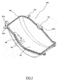
Figure 3 is an upside-down perspective view of thefirst cover element 145a according to an embodiment of the present invention. - In order to make the coupling between the
cover element 145a and thefan impeller housing 210 air-tight so as to prevent leakage of moisturized process air, agasket 305 is provided, which, when thecover element 145a is coupled to thefan impeller housing 210, is sandwiched between the fan impellerhousing border flange 215 and thecover border flange 245. As it will be described in greater detail later on, thegasket 305 works as a friction enhancing element for the surface in contact with a sealing element, such as thefelt disc 220. Thegasket 305 is preferably made of a resilient material, such as a nitrile rubber (e.g., Nitrile Butadiene Rubber or NBR). Advantageously, thegasket 305 may be formed by over-injection molding on thecover border flange 245. It is preferable to form thegasket 305 on the border flange of the cover element instead that on the border flange of the fan impeller housing, because in a molding process thecover element 145a is easier to handle and to be inserted in a mold than thebasement 115. However, if preferred, thegasket 305 may be formed by over-injection molding on the fan impellerhousing border flange 215. Thanks to over-injection techniques, thegasket 305 is essentially integral to, almost in one piece with, thefirst cover element 145a. However, in alternative embodiments of the present invention, it is possible to provide thegasket 305 as a separate element and arrange it on thebasement border 215 or thecover border flange 245. - In a solution according to an embodiment of the present invention, the
gasket 305 is provided along the wholecover border flange 245, for example by means of over-injection, including at least a portion of theseat 505 where the sealingmember 220 is received. Thus, also thesemicircular portion 245a wherein the feltdisc 220 has to be arranged is, at least partly, provided with thegasket 305. In this way, thegasket 305 is able to retain the feltdisc 220 and hold the same in position, thanks to friction forces that arise between the feltdisc 220 and thegasket 305 once thecover element 145a is mounted to thebasement 115, in a better way with respect to the solution known in the art, wherein the gasket is not provided in suchsemicircular portion 245a. More generally, a friction element, such as thegasket 305, is interposed between at least a portion of a sealing member, such as thefelt disc 220, and at least a portion of thepassage 155 provided in theimpeller seat 109 for being passed through by thetransmission member 150. Thus, moisture and pressure leaks from theshaft passage 155 are eliminated, or at least greatly reduced. - Turning to
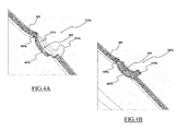
Figures 4A , there is shown an enlarged view of thesemicircular portion 245a, i.e. a portion of theseat 505 receiving therein the sealingmember 220. Thesemicircular portion 245a comprises thegasket 305 according to a first embodiment of the present invention. - In detail, the
semicircular portion 245a comprises afirst sidewall 445a and asecond sidewall 445b delimiting asemicircular bottom wall 445c therebetween. The first and the second sidewalls 445a, 445b are preferably parallel one another and extend in a radial direction relative to the rotational axis of thefan impeller 205. Thebottom wall 445c extends around a part of thetransmission member 150. Thesemicircular portion 245a is advantageously formed in order to fittingly house both thegasket 305 and the feltdisc 220. Analogously, also the preferably half-circular shapedportion 215a comprises a couple of parallel sidewalls delimiting a semicircular bottom wall therebetween. Said sidewalls are preferably parallel one another and extend in a radial direction relative to the rotational axis of thefan impeller 205. The bottom wall extends around a part of thetransmission member 150. In the cavity formed by said sidewalls and the bottom wall is received a part of the feltdisc 220 and, if desired, also a part of a friction element. - The
gasket 305 according to the present invention comprises asemicircular gasket portion 405a provided on at least a part of thesemicircular bottom wall 445c and on thesecond sidewall 445b thereof. Thesemicircular portion 405a of thegasket 305 is adapted to engage the feltdisc 220 and retain it in position after the assembly of the first cover element 145 with thebasement 115. - In order to ensure a proper engagement between the
gasket 305 and the feltdisc 220, thebottom wall 445c is shaped so as to form agasket seat 505 for thesemicircular portion 405a of thegasket 305, and thefirst sidewall 445a is spaced apart from thesecond sidewall 445b by a distance substantially equal to the cross-section of the feltdisc 220 and of thesemicircular portion 405a of thegasket 305 fitted to thesecond sidewall 445b. - It should be noted that in alternative embodiments according to the present invention (not shown in the drawings) the
semicircular gasket portion 405a may be provided on thefirst sidewall 445a of thesemicircular portion 245a instead that on thesecond sidewall 445b thereof. - As an alternative, shown in
Figure 4B , thesemicircular portion 245a of the first cover element 145 may be designed with a further semicircular gasket portion 405b in such a way that both thefirst sidewall 445a and thesecond sidewall 445b of thesemicircular portion 245a result covered with thegasket 305. In this way, the friction forces between the semicircular gasket portion 405b and the feltdisc 220 substantially have a symmetrical distribution with respect to thebottom wall 445c. Further preferably, the wholebottom wall 445c may be covered by thegasket 305. -
Figures 5A and5B show cross-sectional front and side views of the first cover element 145 mounted on thebasement 115. - As previously described, the friction forces between the felt
disc 220 and thesemicircular gasket portion 405a positioned in itsgasket seat 505 prevents the former from being dragged in rotation by theshaft 150 during operation thus, preventing a loosening of the sealing action provided by the feltdisc 220 and, subsequently, prevents detrimental effects on the feltdisc 220 itself, such as raveling. Moreover, the engagement between the feltdisc 220 and thesemicircular gasket part 405a is able to improve the airtight sealing of thepassage 155. -
Figure 6 is a perspective and exploded view of a detail of thefirst cover element 145a with thesupport element 240 for anair temperature sensor 600 according to an embodiment of the present invention. - The
support element 240 is advantageously made of a thermoplastic elastomer (such as a silicone rubber) and thetemperature sensor 600 is airtight fitted in thesupport element 240. In an embodiment of the present invention, thesupport element 240 is formed integral with thefirst cover element 145a, for example, by over-injection molding over thecover element 145a, or by forming thecover element 145a and thesupport element 240 by co-injection molding. Forming thesupport element 240 integral with thefirst cover element 145a also ensures a better airtight coupling of the latter with the former. The over-injection or co-injection molding process allows reducing the overall assembly costs and times, since manufacturing phases for forming thesupport element 240 and inserting it into thereceptacle 247 are no longer required. - Referring again to
Figure 2 , and toFigure 7 , which shows an enlarged perspective view of a detail of thebasement 115, thebasement 115 advantageously comprises aspring recess 250 for thecoil spring 165. - In an embodiment of the present invention, the
spring recess 250 is advantageously provided with at least one reinforcement element, such as a first reinforcingrib 255. Advantageously, the first reinforcingrib 255 is provided in abase surface 250a of thespring recess 250. Aneyelet 260 is provided below thespring recess 250 for the engagement of a hooked end of thecoil spring 165 to thebasement 115. The first reinforcingrib 255 and theeyelet 260 have respective symmetry axes lying on a same symmetry plane S, i.e. the first reinforcingrib 255 and theeyelet 260 are aligned one another. - Preferably, although not limitatively, the first reinforcing
rib 255 is advantageously made of the same polymeric material as thebasement 115 and, more preferably, the first reinforcingrib 255 is formed monolithically, in one piece with thebasement 115. Alternatively, the first reinforcingrib 255 may be made of a denser polymeric material or of metal, ensuring a greater resistance thereof, or the first reinforcingrib 255 may be made of a resilient material (such as an elastomeric material), the first reinforcingrib 255 may in this case be attached to thebasement 115 in any suitable manner e.g., by means of a snap-fit engagement, gluing, welding, etc. - The first reinforcing
rib 255 is adapted to reinforce locally the structure of thebasement 115. Preferably, although not necessarily, the first reinforcingrib 255 has substantially the shape of a prism with two right-angled triangle opposite faces, only one of which is visible in theFigure 2 and denoted withreference numeral 255a, protruding vertically from abase surface 250a. The first reinforcingrib 255 that protrudes from abase surface 250a, forms a plane that is inclined relative to thebase surface 250a with an angle comprised between 0° and 60° and more preferably between 0° and 45°. The first reinforcingrib 255 preferably extends from aborder 250c of thespring recess 250 up to aback wall 250b of thespring recess 250 which protrudes substantially perpendicularly from thebase surface 250a. The distance between the inclined plane formed by the first reinforcingrib 255 and thebase surface 250a is maximum in the region where the first reinforcingrib 255 joins theback wall 250b of thespring recess 250 and is minimum in a region adjacent to aborder 250c of thespring recess 250. - Advantageously, the first reinforcing
rib 255 is adapted to reinforce thebasement 115 substantially at thespring recess 250. In detail, the first reinforcingrib 255 reinforces thebase surface 250a of thespring recess 250, where it is more likely that thecoil spring 165 beats against thebasement 115 if for example thecoil spring 165 is accidentally released from the hold of a technician or of an assembling machine during the assembly of thelaundry machine 100. The first reinforcingrib 255 is able to absorb the impact forces of the recoilingcoil spring 165 without suffering damages and, at the same time, preventing damages to thebasement 115 which otherwise might be broken by the impact. - In a preferred embodiment, a further reinforcement element may be provided, for example a second reinforcing
rib 755. Advantageously, the second reinforcingrib 755 is provided on thebasement 115 between thespring recess 250 and theeyelet 260; the reinforcingribs eyelet 260, have a symmetry plane S in common, i.e., the reinforcingribs eyelet 260 are mutually aligned. - Preferably, although not limitatively, the second reinforcing
rib 755 may advantageously be made of the same polymeric material of thebasement 115 and, more preferably, formed monolithically, in one piece therewith. Alternatively, the second reinforcingrib 755 may be made of a denser polymeric material than the basement material or it can be made of metal material thereby ensuring a greater resistance. The second reinforcingrib 755 may further be made of a resilient material such as an elastomeric material in order to act as a cushion for thecoil spring 165 recoiling; in these cases, the second reinforcingrib 755 may be attached to thebasement 115 in any suitable manner such as via a snap-fit engagement, glue, welding, and the like. - The second reinforcing
rib 755 is adapted to reinforce locally the structure of thebasement 115. - Preferably, although not limitatively, the second reinforcing
rib 755 comprises a prism having two trapezoidal opposite faces, only one of which is visible in theFigure 7 and denoted withreference numeral 755a. Advantageously, the second reinforcingrib 755 may comprise an elongated portion substantially perpendicular to the elongated portion of the first reinforcingrib 255 and to theeyelet 260. Furthermore, the second reinforcingrib 755 may also comprise a second prism having two right triangle opposite faces, which protrudes substantially from the middle of the first prism towards the first reinforcingrib 255 at theborder 250c of thespring recess 250, thus being aligned with theeyelet 260 and the first reinforcingrib 255. - The second reinforcing
rib 755 reinforces abasement 115 portion between theborder 250c of thespring recess 250 and theeyelet 260. Therefore, the second reinforcingrib 755, along with improving a resistance of thebasement 115 against impacts of thecoil spring 165, may also be advantageously adapted to reinforce a portion of thebasement 115 where the hooked end of thecoil spring 165 may abut once engaged in theeyelet 260 making the same more resistant against oscillating forces during thelaundry machine 100 operation. - It should be noted that, in other embodiments of the present invention (not shown in the figures), more than two reinforcing ribs may be provided, and/or such reinforcing ribs may have different shapes.
-
Figure 8 shows an enlarged cross-sectional view of thebasement 115 with thecoil spring 165 engaged within theeyelet 260 with respect to the symmetry plane S. Particularly,Figure 8 shows a rest position reached by thecoil spring 165 after an impact with thebasement 115. - When the
coil spring 165 escapes from the hold of the technician or the assembling machine, for example during the assembly of thelaundry machine 100, thecoil spring 165 hits the first reinforcingrib 255 and/or the second reinforcingrib 755 which absorb the recoiling strength and disperse the same in thebase surface 250a and, therefrom, in thewhole basement 115. Advantageously, the dispersion of the spring recoiling strength prevents damages to thebasement 115. - After the impact between the
coil spring 165 and the first reinforcingrib 255 and/or the second reinforcingrib 755, thecoil spring 165 may bounce repeatedly, due to the action-reaction principle and residual recoiling force, which is consumed bounce after bounce. Advantageously, the right triangle shape of the first reinforcingrib 255 makes thecoil spring 165 slide towards the second reinforcingrib 755 until thespring 165 reaches a rest position, which is slanted outwardly with respect to thespring recess 250 and the recessedarea 160 receiving themotor 120, with a firsthooked end 865a of thecoil spring 165 abutting against aninside surface 805 opposite to thebase surface 250a of thespring recess 250; thecoil spring 165 is thus kept bounded to theeyelet 260, while a secondhooked end 865b of thecoil spring 165 is free and facing towards the outside of thebasement 115. Therefore, thecoil spring 165 bounces oscillating substantially along the plane S, from the rest position towards thespring recess 250 and vice versa, until a residual spring force fades. The inclined plane formed by the first reinforcingrib 255 helps to incline thecoil spring 165 relative to thebase surface 250a of thespring recess 250 so as to avoid that thespring 165 hits thebase surface 250a with an impact direction perpendicular thereto. The provision of the first reinforcingrib 255 with its inclined plane allows only a component of the overall impact force to act on thebase surface 250a, thereby reducing the risk of damaging it. In addition, thecoil spring 165 is advantageously retained engaged within theeyelet 260, even in the case of particularly intense recoiling strength. Indeed, thecoil spring 165, falling downwards abuts the second reinforcingrib 755, which blocks thecoil spring 165 before it can rotate sufficiently to disengage the firsthooked end 865a from theeyelet 260. - In this way, it is possible to effectively disperse spring forces and prevent damages to the
basement 115. Moreover, the controlled bouncing of thecoil spring 165 prevents the same from engaging any other part of thelaundry machine 100 while bouncing, which may complicate and/or prolong the assembly operation of the laundry machine and increase the manufacturing costs. Therefore, laundry machines according to the present invention above described have an overall lower manufacturing cost than laundry machines known in the prior art. This is possible thanks to the fact that the basement will not suffer any damage by an impact, and therefore will not be substituted. Furthermore, also the overall manufacturing time is reduced, since no substitution time is required and the elastic element will not be tangled by any other parts of the laundry machine - thanks to the reinforce elements provided. - It should be noted that both a cover element comprising the gasket along its border but not the support element for the sensor element or, vice versa, a cover element having the support element for the sensor element but not the gasket along its border may be provided without departing from the scope of the present invention as described. Nevertheless, also only a basement featuring one or more reinforcing elements as above described should be considered within the scope of the present invention. In other words, the various solutions of gasket for an impeller housing cover element, a temperature sensor support formed integrally to an impeller housing cover element, reinforcing elements in the basement for strengthening it where the coil spring is hooked, may each be implemented individually and not necessarily in combination one with the other.
- In the description above, only the
first cover element 145a has been considered, although similar consideration may be applied equivalently to thesecond cover element 145b as well, and in general to any additional cover element for closing the housing of an impeller.
Claims (15)
- A laundry machine (100) for treating laundry items comprising:an outer casing (105) housing a rotatable laundry drum (110) for containing laundry items to be treated,a fluid flow path comprising at least one seat (109) adapted to receive a fluid impeller element (205),a transmission member (150) extending through a passage (155) formed in said seat (109) to operate the impeller element (105),a sealing member (220) arranged in the passage (155),
characterized in thata friction element (305) is arranged between at least a portion of the sealing member (220) and at least a portion of said passage (155). - A laundry machine (100) according to claim 1 wherein said fluid flow path is formed in a basement (115) of the machine (100).
- A laundry machine (100) according to claim 1 or 2 wherein the fluid flow path is in fluid communication with the laundry drum (110) or with the environment outside the machine (100).
- A laundry machine (100) according to any preceding claim wherein said seat (109) comprises a first housing (210) formed in a basement (115) of the machine (100) and a second housing (108) formed in a cover element (145a, 145b) associable to the basement (115) over the first housing (210).
- A laundry machine (100) according to claim 4 wherein said passage (155) is partly formed in the first housing (210) and partly in the second housing (108) formed in a cover element (145a, 145b).
- A laundry machine (100) according to claim 4 or 5 wherein said friction element (305) is provided on a border flange (215, 245) either of the first housing (210) or the second housing (108) formed in a cover element (145a, 145b).
- A laundry machine (100) according to any preceding claim wherein said passage (155) comprises walls (445a, 445b; 445e, 445f) extending radially relative to a rotational axis of the impeller element (105) and further walls (445c, 445f) extending around a part of the transmission member (150).
- A laundry machine (100) according to claim 7 wherein said friction element (305) is provided in at least a part of one or more of said walls (445a, 445b; 445e, 445f, 445c, 445f).
- A laundry machine (100) according to any preceding claim wherein said friction element (305) is a gasket formed by over-injection molding.
- A laundry machine (100) according to any preceding claim wherein said transmission member is a shaft (150) which is connected to a motor device (120) and the sealing member (220) is a disc-shaped body extending around the shaft (150).
- A laundry machine (100) according to any of the preceding claims, further comprising:a motor (120) for driving at least the laundry drum (110),a basement (115), anda damping element (165) adapted to couple the motor (120) with the basement (115) for reducing vibrations of the motor (120) during operation, whereinthe basement (115) comprises at least one reinforcement element (255, 755) adapted to prevent damages to the basement (115) in case the damping element (165) recoils towards the basement (115).
- The laundry machine (100) according to claim 11, wherein the basement (115) further comprises:A recess (250) adapted to allow the damping element (165) to extend between the motor (120) and the basement (115) without interfering with the latter,a retaining portion (260) adapted to be engaged by a first end (865a) of the damping element (165), andwherein the at least one reinforcement element (255, 755) comprises a first reinforcement element (255) provided on a base surface (250a) of the recess (250) so as to intercept an impact direction of the damping element (165) towards the basement (115), anda second reinforcement element (755) provided on the basement (115) between the retaining portion (260) and a border (250c) of the recess (250).
- A laundry machine (100) according to any of the preceding claims comprising
a basement (115), and
at least one cover element (145a, 145b) associable to the basement (115) comprising a plurality of protruding portions (225a, 225b, 225c) in which trough-holes are formed for the insertion of a fastening element, each protruding portion (225a, 225b, 225c) protruding from a cover border flange (245),
the basement (115) further comprises a plurality of appendages (230a, 230b, 230c) protruding from a base border (215), each for matching one corresponding protruding portion (225a, 225b, 225c), and wherein
at least one protruding portion (225b) of the plurality protruding portions (225a, 225b, 225c) and at least one matching appendage (230b) of the plurality of appendages (230a, 230b, 230c) are formed transversal with respect to the other protruding portions (225a, 225c) of the plurality protruding portion (225a, 225b, 225c) and the other matching appendages (230a, 230c) of the plurality of appendages (230a, 230b, 230c). - The laundry machine (100) according to any of the preceding claims, wherein said seat (109) comprises a cover element (145a, 145b) having
a receptacle (247) for accommodating a sensor (600),
a support element (240) for supporting the sensor, said support element (240) being formed integral with the cover element (145a, 145b) by means of an over-injection or co-injection molding. - The laundry machine (100) according to claim 14, wherein support element (240) is adapted to support the sensor (600) by engaging said sensor in an airtight manner.
Priority Applications (2)
| Application Number | Priority Date | Filing Date | Title |
|---|---|---|---|
| EP12171518.9A EP2674524B1 (en) | 2012-06-11 | 2012-06-11 | Improved laundry machine |
| PCT/EP2013/061779 WO2013186134A1 (en) | 2012-06-11 | 2013-06-07 | Improved laundry machine |
Applications Claiming Priority (1)
| Application Number | Priority Date | Filing Date | Title |
|---|---|---|---|
| EP12171518.9A EP2674524B1 (en) | 2012-06-11 | 2012-06-11 | Improved laundry machine |
Publications (2)
| Publication Number | Publication Date |
|---|---|
| EP2674524A1 true EP2674524A1 (en) | 2013-12-18 |
| EP2674524B1 EP2674524B1 (en) | 2017-03-01 |
Family
ID=48577082
Family Applications (1)
| Application Number | Title | Priority Date | Filing Date |
|---|---|---|---|
| EP12171518.9A Active EP2674524B1 (en) | 2012-06-11 | 2012-06-11 | Improved laundry machine |
Country Status (2)
| Country | Link |
|---|---|
| EP (1) | EP2674524B1 (en) |
| WO (1) | WO2013186134A1 (en) |
Cited By (3)
| Publication number | Priority date | Publication date | Assignee | Title |
|---|---|---|---|---|
| EP3029194A1 (en) * | 2014-12-05 | 2016-06-08 | Electrolux Appliances Aktiebolag | Laundry dryer |
| EP3124688A1 (en) * | 2015-07-27 | 2017-02-01 | Electrolux Appliances Aktiebolag | A laundry dryer |
| CN107974793A (en) * | 2017-11-21 | 2018-05-01 | 无锡小天鹅股份有限公司 | Impeller, wave-wheel assembly and washing machine |
Citations (3)
| Publication number | Priority date | Publication date | Assignee | Title |
|---|---|---|---|---|
| DE10001702C1 (en) * | 2000-01-18 | 2001-05-23 | Whirlpool Co | Condensation laundry dryer has electric motor drive unit fitted with process gas fan wheel and removable pre-assembled cold air fan unit at opposite ends of motor shaft |
| US20090064533A1 (en) * | 2005-06-28 | 2009-03-12 | Kazutoshi Nakiri | Washer-dryer |
| DE102010029491A1 (en) * | 2009-06-17 | 2011-01-13 | BSH Bosch und Siemens Hausgeräte GmbH | Assembly and household tumble dryer with this assembly |
-
2012
- 2012-06-11 EP EP12171518.9A patent/EP2674524B1/en active Active
-
2013
- 2013-06-07 WO PCT/EP2013/061779 patent/WO2013186134A1/en not_active Ceased
Patent Citations (3)
| Publication number | Priority date | Publication date | Assignee | Title |
|---|---|---|---|---|
| DE10001702C1 (en) * | 2000-01-18 | 2001-05-23 | Whirlpool Co | Condensation laundry dryer has electric motor drive unit fitted with process gas fan wheel and removable pre-assembled cold air fan unit at opposite ends of motor shaft |
| US20090064533A1 (en) * | 2005-06-28 | 2009-03-12 | Kazutoshi Nakiri | Washer-dryer |
| DE102010029491A1 (en) * | 2009-06-17 | 2011-01-13 | BSH Bosch und Siemens Hausgeräte GmbH | Assembly and household tumble dryer with this assembly |
Cited By (5)
| Publication number | Priority date | Publication date | Assignee | Title |
|---|---|---|---|---|
| EP3029194A1 (en) * | 2014-12-05 | 2016-06-08 | Electrolux Appliances Aktiebolag | Laundry dryer |
| US10184205B2 (en) | 2014-12-05 | 2019-01-22 | Electrolux Appliances Aktiebolag | Laundry dryer with drainable motor shaft seat |
| EP3124688A1 (en) * | 2015-07-27 | 2017-02-01 | Electrolux Appliances Aktiebolag | A laundry dryer |
| CN107974793A (en) * | 2017-11-21 | 2018-05-01 | 无锡小天鹅股份有限公司 | Impeller, wave-wheel assembly and washing machine |
| CN107974793B (en) * | 2017-11-21 | 2020-06-16 | 无锡小天鹅电器有限公司 | Impeller, impeller assembly and washing machine |
Also Published As
| Publication number | Publication date |
|---|---|
| WO2013186134A1 (en) | 2013-12-19 |
| EP2674524B1 (en) | 2017-03-01 |
Similar Documents
| Publication | Publication Date | Title |
|---|---|---|
| RU2544828C9 (en) | Washing machine and its control method | |
| AU2015309202B2 (en) | Laundry dryer | |
| EP3582373B1 (en) | Brushless dc motor and drain pump having the same | |
| EP2990521B1 (en) | Laundry dryer | |
| EP3124679B1 (en) | Laundry treating machine | |
| EP2674524B1 (en) | Improved laundry machine | |
| CN101666024B (en) | Laundry drier and drier | |
| KR20070004508A (en) | washer | |
| EP2843114B1 (en) | Rotary-drum laundry dryer | |
| US20050223592A1 (en) | Apparatus for driving drum of clothes dryer | |
| JP4541023B2 (en) | Washing and drying machine | |
| US20130031797A1 (en) | Laundry machine having a drying function | |
| KR101606663B1 (en) | Clothes dryer | |
| EP2631356B1 (en) | Rotary-drum laundry dryer | |
| JP5033089B2 (en) | Laundry dryer and dryer | |
| KR102841287B1 (en) | A Clothes Treatment Apparatus | |
| JP2015051178A (en) | Washing and drying machine | |
| US12590394B2 (en) | Air bypass seal with backer for improved drying performance in a combination washer/dryer | |
| KR101033586B1 (en) | Drum washing machine | |
| JP2004033409A (en) | Vertical washing and drying machine | |
| JP6572192B2 (en) | Drum washing machine | |
| KR20250098908A (en) | A laundry treating apparatus | |
| EP2843113A1 (en) | Rotary-drum laundry dryer | |
| WO2025251927A1 (en) | Washer-dryer | |
| KR101861662B1 (en) | Laundry Machine |
Legal Events
| Date | Code | Title | Description |
|---|---|---|---|
| PUAI | Public reference made under article 153(3) epc to a published international application that has entered the european phase |
Free format text: ORIGINAL CODE: 0009012 |
|
| AK | Designated contracting states |
Kind code of ref document: A1 Designated state(s): AL AT BE BG CH CY CZ DE DK EE ES FI FR GB GR HR HU IE IS IT LI LT LU LV MC MK MT NL NO PL PT RO RS SE SI SK SM TR |
|
| AX | Request for extension of the european patent |
Extension state: BA ME |
|
| 17P | Request for examination filed |
Effective date: 20140616 |
|
| RBV | Designated contracting states (corrected) |
Designated state(s): AL AT BE BG CH CY CZ DE DK EE ES FI FR GB GR HR HU IE IS IT LI LT LU LV MC MK MT NL NO PL PT RO RS SE SI SK SM TR |
|
| GRAP | Despatch of communication of intention to grant a patent |
Free format text: ORIGINAL CODE: EPIDOSNIGR1 |
|
| INTG | Intention to grant announced |
Effective date: 20160617 |
|
| GRAJ | Information related to disapproval of communication of intention to grant by the applicant or resumption of examination proceedings by the epo deleted |
Free format text: ORIGINAL CODE: EPIDOSDIGR1 |
|
| GRAP | Despatch of communication of intention to grant a patent |
Free format text: ORIGINAL CODE: EPIDOSNIGR1 |
|
| INTC | Intention to grant announced (deleted) | ||
| INTG | Intention to grant announced |
Effective date: 20160927 |
|
| GRAS | Grant fee paid |
Free format text: ORIGINAL CODE: EPIDOSNIGR3 |
|
| GRAA | (expected) grant |
Free format text: ORIGINAL CODE: 0009210 |
|
| AK | Designated contracting states |
Kind code of ref document: B1 Designated state(s): AL AT BE BG CH CY CZ DE DK EE ES FI FR GB GR HR HU IE IS IT LI LT LU LV MC MK MT NL NO PL PT RO RS SE SI SK SM TR |
|
| REG | Reference to a national code |
Ref country code: GB Ref legal event code: FG4D |
|
| REG | Reference to a national code |
Ref country code: CH Ref legal event code: EP Ref country code: AT Ref legal event code: REF Ref document number: 871477 Country of ref document: AT Kind code of ref document: T Effective date: 20170315 |
|
| REG | Reference to a national code |
Ref country code: IE Ref legal event code: FG4D |
|
| REG | Reference to a national code |
Ref country code: DE Ref legal event code: R096 Ref document number: 602012029130 Country of ref document: DE |
|
| REG | Reference to a national code |
Ref country code: NL Ref legal event code: MP Effective date: 20170301 |
|
| REG | Reference to a national code |
Ref country code: LT Ref legal event code: MG4D |
|
| REG | Reference to a national code |
Ref country code: AT Ref legal event code: MK05 Ref document number: 871477 Country of ref document: AT Kind code of ref document: T Effective date: 20170301 |
|
| PG25 | Lapsed in a contracting state [announced via postgrant information from national office to epo] |
Ref country code: FI Free format text: LAPSE BECAUSE OF FAILURE TO SUBMIT A TRANSLATION OF THE DESCRIPTION OR TO PAY THE FEE WITHIN THE PRESCRIBED TIME-LIMIT Effective date: 20170301 Ref country code: HR Free format text: LAPSE BECAUSE OF FAILURE TO SUBMIT A TRANSLATION OF THE DESCRIPTION OR TO PAY THE FEE WITHIN THE PRESCRIBED TIME-LIMIT Effective date: 20170301 Ref country code: NO Free format text: LAPSE BECAUSE OF FAILURE TO SUBMIT A TRANSLATION OF THE DESCRIPTION OR TO PAY THE FEE WITHIN THE PRESCRIBED TIME-LIMIT Effective date: 20170601 Ref country code: LT Free format text: LAPSE BECAUSE OF FAILURE TO SUBMIT A TRANSLATION OF THE DESCRIPTION OR TO PAY THE FEE WITHIN THE PRESCRIBED TIME-LIMIT Effective date: 20170301 Ref country code: GR Free format text: LAPSE BECAUSE OF FAILURE TO SUBMIT A TRANSLATION OF THE DESCRIPTION OR TO PAY THE FEE WITHIN THE PRESCRIBED TIME-LIMIT Effective date: 20170602 |
|
| PG25 | Lapsed in a contracting state [announced via postgrant information from national office to epo] |
Ref country code: ES Free format text: LAPSE BECAUSE OF FAILURE TO SUBMIT A TRANSLATION OF THE DESCRIPTION OR TO PAY THE FEE WITHIN THE PRESCRIBED TIME-LIMIT Effective date: 20170301 Ref country code: RS Free format text: LAPSE BECAUSE OF FAILURE TO SUBMIT A TRANSLATION OF THE DESCRIPTION OR TO PAY THE FEE WITHIN THE PRESCRIBED TIME-LIMIT Effective date: 20170301 Ref country code: BG Free format text: LAPSE BECAUSE OF FAILURE TO SUBMIT A TRANSLATION OF THE DESCRIPTION OR TO PAY THE FEE WITHIN THE PRESCRIBED TIME-LIMIT Effective date: 20170601 Ref country code: SE Free format text: LAPSE BECAUSE OF FAILURE TO SUBMIT A TRANSLATION OF THE DESCRIPTION OR TO PAY THE FEE WITHIN THE PRESCRIBED TIME-LIMIT Effective date: 20170301 Ref country code: LV Free format text: LAPSE BECAUSE OF FAILURE TO SUBMIT A TRANSLATION OF THE DESCRIPTION OR TO PAY THE FEE WITHIN THE PRESCRIBED TIME-LIMIT Effective date: 20170301 Ref country code: AT Free format text: LAPSE BECAUSE OF FAILURE TO SUBMIT A TRANSLATION OF THE DESCRIPTION OR TO PAY THE FEE WITHIN THE PRESCRIBED TIME-LIMIT Effective date: 20170301 |
|
| PG25 | Lapsed in a contracting state [announced via postgrant information from national office to epo] |
Ref country code: NL Free format text: LAPSE BECAUSE OF FAILURE TO SUBMIT A TRANSLATION OF THE DESCRIPTION OR TO PAY THE FEE WITHIN THE PRESCRIBED TIME-LIMIT Effective date: 20170301 |
|
| PG25 | Lapsed in a contracting state [announced via postgrant information from national office to epo] |
Ref country code: RO Free format text: LAPSE BECAUSE OF FAILURE TO SUBMIT A TRANSLATION OF THE DESCRIPTION OR TO PAY THE FEE WITHIN THE PRESCRIBED TIME-LIMIT Effective date: 20170301 Ref country code: CZ Free format text: LAPSE BECAUSE OF FAILURE TO SUBMIT A TRANSLATION OF THE DESCRIPTION OR TO PAY THE FEE WITHIN THE PRESCRIBED TIME-LIMIT Effective date: 20170301 Ref country code: IT Free format text: LAPSE BECAUSE OF FAILURE TO SUBMIT A TRANSLATION OF THE DESCRIPTION OR TO PAY THE FEE WITHIN THE PRESCRIBED TIME-LIMIT Effective date: 20170301 Ref country code: SK Free format text: LAPSE BECAUSE OF FAILURE TO SUBMIT A TRANSLATION OF THE DESCRIPTION OR TO PAY THE FEE WITHIN THE PRESCRIBED TIME-LIMIT Effective date: 20170301 Ref country code: EE Free format text: LAPSE BECAUSE OF FAILURE TO SUBMIT A TRANSLATION OF THE DESCRIPTION OR TO PAY THE FEE WITHIN THE PRESCRIBED TIME-LIMIT Effective date: 20170301 |
|
| PG25 | Lapsed in a contracting state [announced via postgrant information from national office to epo] |
Ref country code: PL Free format text: LAPSE BECAUSE OF FAILURE TO SUBMIT A TRANSLATION OF THE DESCRIPTION OR TO PAY THE FEE WITHIN THE PRESCRIBED TIME-LIMIT Effective date: 20170301 Ref country code: SM Free format text: LAPSE BECAUSE OF FAILURE TO SUBMIT A TRANSLATION OF THE DESCRIPTION OR TO PAY THE FEE WITHIN THE PRESCRIBED TIME-LIMIT Effective date: 20170301 Ref country code: PT Free format text: LAPSE BECAUSE OF FAILURE TO SUBMIT A TRANSLATION OF THE DESCRIPTION OR TO PAY THE FEE WITHIN THE PRESCRIBED TIME-LIMIT Effective date: 20170703 Ref country code: IS Free format text: LAPSE BECAUSE OF FAILURE TO SUBMIT A TRANSLATION OF THE DESCRIPTION OR TO PAY THE FEE WITHIN THE PRESCRIBED TIME-LIMIT Effective date: 20170701 |
|
| REG | Reference to a national code |
Ref country code: DE Ref legal event code: R097 Ref document number: 602012029130 Country of ref document: DE |
|
| PLBE | No opposition filed within time limit |
Free format text: ORIGINAL CODE: 0009261 |
|
| STAA | Information on the status of an ep patent application or granted ep patent |
Free format text: STATUS: NO OPPOSITION FILED WITHIN TIME LIMIT |
|
| PG25 | Lapsed in a contracting state [announced via postgrant information from national office to epo] |
Ref country code: DK Free format text: LAPSE BECAUSE OF FAILURE TO SUBMIT A TRANSLATION OF THE DESCRIPTION OR TO PAY THE FEE WITHIN THE PRESCRIBED TIME-LIMIT Effective date: 20170301 Ref country code: MC Free format text: LAPSE BECAUSE OF FAILURE TO SUBMIT A TRANSLATION OF THE DESCRIPTION OR TO PAY THE FEE WITHIN THE PRESCRIBED TIME-LIMIT Effective date: 20170301 |
|
| REG | Reference to a national code |
Ref country code: CH Ref legal event code: PL |
|
| 26N | No opposition filed |
Effective date: 20171204 |
|
| GBPC | Gb: european patent ceased through non-payment of renewal fee |
Effective date: 20170611 |
|
| PG25 | Lapsed in a contracting state [announced via postgrant information from national office to epo] |
Ref country code: SI Free format text: LAPSE BECAUSE OF FAILURE TO SUBMIT A TRANSLATION OF THE DESCRIPTION OR TO PAY THE FEE WITHIN THE PRESCRIBED TIME-LIMIT Effective date: 20170301 |
|
| REG | Reference to a national code |
Ref country code: IE Ref legal event code: MM4A |
|
| REG | Reference to a national code |
Ref country code: FR Ref legal event code: ST Effective date: 20180228 |
|
| PG25 | Lapsed in a contracting state [announced via postgrant information from national office to epo] |
Ref country code: GB Free format text: LAPSE BECAUSE OF NON-PAYMENT OF DUE FEES Effective date: 20170611 Ref country code: CH Free format text: LAPSE BECAUSE OF NON-PAYMENT OF DUE FEES Effective date: 20170630 Ref country code: LI Free format text: LAPSE BECAUSE OF NON-PAYMENT OF DUE FEES Effective date: 20170630 Ref country code: IE Free format text: LAPSE BECAUSE OF NON-PAYMENT OF DUE FEES Effective date: 20170611 Ref country code: LU Free format text: LAPSE BECAUSE OF NON-PAYMENT OF DUE FEES Effective date: 20170611 |
|
| PG25 | Lapsed in a contracting state [announced via postgrant information from national office to epo] |
Ref country code: FR Free format text: LAPSE BECAUSE OF NON-PAYMENT OF DUE FEES Effective date: 20170630 |
|
| REG | Reference to a national code |
Ref country code: BE Ref legal event code: MM Effective date: 20170630 |
|
| PG25 | Lapsed in a contracting state [announced via postgrant information from national office to epo] |
Ref country code: BE Free format text: LAPSE BECAUSE OF NON-PAYMENT OF DUE FEES Effective date: 20170630 |
|
| PG25 | Lapsed in a contracting state [announced via postgrant information from national office to epo] |
Ref country code: MT Free format text: LAPSE BECAUSE OF NON-PAYMENT OF DUE FEES Effective date: 20170611 |
|
| PG25 | Lapsed in a contracting state [announced via postgrant information from national office to epo] |
Ref country code: HU Free format text: LAPSE BECAUSE OF FAILURE TO SUBMIT A TRANSLATION OF THE DESCRIPTION OR TO PAY THE FEE WITHIN THE PRESCRIBED TIME-LIMIT; INVALID AB INITIO Effective date: 20120611 |
|
| PG25 | Lapsed in a contracting state [announced via postgrant information from national office to epo] |
Ref country code: CY Free format text: LAPSE BECAUSE OF NON-PAYMENT OF DUE FEES Effective date: 20170301 |
|
| PG25 | Lapsed in a contracting state [announced via postgrant information from national office to epo] |
Ref country code: MK Free format text: LAPSE BECAUSE OF FAILURE TO SUBMIT A TRANSLATION OF THE DESCRIPTION OR TO PAY THE FEE WITHIN THE PRESCRIBED TIME-LIMIT Effective date: 20170301 |
|
| PG25 | Lapsed in a contracting state [announced via postgrant information from national office to epo] |
Ref country code: TR Free format text: LAPSE BECAUSE OF FAILURE TO SUBMIT A TRANSLATION OF THE DESCRIPTION OR TO PAY THE FEE WITHIN THE PRESCRIBED TIME-LIMIT Effective date: 20170301 |
|
| PG25 | Lapsed in a contracting state [announced via postgrant information from national office to epo] |
Ref country code: AL Free format text: LAPSE BECAUSE OF FAILURE TO SUBMIT A TRANSLATION OF THE DESCRIPTION OR TO PAY THE FEE WITHIN THE PRESCRIBED TIME-LIMIT Effective date: 20170301 |
|
| P01 | Opt-out of the competence of the unified patent court (upc) registered |
Effective date: 20230625 |
|
| PGFP | Annual fee paid to national office [announced via postgrant information from national office to epo] |
Ref country code: DE Payment date: 20250626 Year of fee payment: 14 |