EP2674331B1 - Holding device - Google Patents
Holding device Download PDFInfo
- Publication number
- EP2674331B1 EP2674331B1 EP20130163495 EP13163495A EP2674331B1 EP 2674331 B1 EP2674331 B1 EP 2674331B1 EP 20130163495 EP20130163495 EP 20130163495 EP 13163495 A EP13163495 A EP 13163495A EP 2674331 B1 EP2674331 B1 EP 2674331B1
- Authority
- EP
- European Patent Office
- Prior art keywords
- holder
- holding device
- housing
- spring clamp
- locking element
- Prior art date
- Legal status (The legal status is an assumption and is not a legal conclusion. Google has not performed a legal analysis and makes no representation as to the accuracy of the status listed.)
- Not-in-force
Links
Images


Classifications
-
- B—PERFORMING OPERATIONS; TRANSPORTING
- B60—VEHICLES IN GENERAL
- B60R—VEHICLES, VEHICLE FITTINGS, OR VEHICLE PARTS, NOT OTHERWISE PROVIDED FOR
- B60R11/00—Arrangements for holding or mounting articles, not otherwise provided for
- B60R11/02—Arrangements for holding or mounting articles, not otherwise provided for for radio sets, television sets, telephones, or the like; Arrangement of controls thereof
-
- B—PERFORMING OPERATIONS; TRANSPORTING
- B60—VEHICLES IN GENERAL
- B60R—VEHICLES, VEHICLE FITTINGS, OR VEHICLE PARTS, NOT OTHERWISE PROVIDED FOR
- B60R11/00—Arrangements for holding or mounting articles, not otherwise provided for
- B60R11/04—Mounting of cameras operative during drive; Arrangement of controls thereof relative to the vehicle
-
- B—PERFORMING OPERATIONS; TRANSPORTING
- B60—VEHICLES IN GENERAL
- B60R—VEHICLES, VEHICLE FITTINGS, OR VEHICLE PARTS, NOT OTHERWISE PROVIDED FOR
- B60R11/00—Arrangements for holding or mounting articles, not otherwise provided for
- B60R2011/0001—Arrangements for holding or mounting articles, not otherwise provided for characterised by position
- B60R2011/0003—Arrangements for holding or mounting articles, not otherwise provided for characterised by position inside the vehicle
- B60R2011/0026—Windows, e.g. windscreen
-
- B—PERFORMING OPERATIONS; TRANSPORTING
- B60—VEHICLES IN GENERAL
- B60R—VEHICLES, VEHICLE FITTINGS, OR VEHICLE PARTS, NOT OTHERWISE PROVIDED FOR
- B60R11/00—Arrangements for holding or mounting articles, not otherwise provided for
- B60R2011/0042—Arrangements for holding or mounting articles, not otherwise provided for characterised by mounting means
- B60R2011/0049—Arrangements for holding or mounting articles, not otherwise provided for characterised by mounting means for non integrated articles
- B60R2011/0064—Connection with the article
- B60R2011/0071—Connection with the article using latches, clips, clamps, straps or the like
-
- G—PHYSICS
- G01—MEASURING; TESTING
- G01D—MEASURING NOT SPECIALLY ADAPTED FOR A SPECIFIC VARIABLE; ARRANGEMENTS FOR MEASURING TWO OR MORE VARIABLES NOT COVERED IN A SINGLE OTHER SUBCLASS; TARIFF METERING APPARATUS; MEASURING OR TESTING NOT OTHERWISE PROVIDED FOR
- G01D11/00—Component parts of measuring arrangements not specially adapted for a specific variable
- G01D11/30—Supports specially adapted for an instrument; Supports specially adapted for a set of instruments
Definitions
- the invention relates to a receiving device for electrical components in a motor vehicle according to the type of claim 1.
- the camera systems described and used in the automotive field are compact in a housing, i. Optics, chip and the electronics directly assigned to the chip are combined in a one-piece housing. This compact unit is then inserted into a corresponding receptacle on the motor vehicle.
- a known application is a surround camera, by means of which the external environment of the vehicle - in particular the rear area - recorded and displayed on an indoor screen.
- Previous surround cameras are usually housed in a plastic housing.
- As an on-vehicle recording is an opening into which the housing of the camera is inserted and locked in it.
- the receptacle or the housing have for fixing the camera corresponding latching elements, latching tongues, as well as fixing and insertion ribs.
- Metal housing of camera systems with more complex optics or larger image chips can not in these known recording arrangements or not be fixed without additional effort.
- the spring clip 1 is pivotally connected via a spring receptacle with a receptacle for an electronic module.
- the spring receptacle 2 is not hinged to the receiving frame 6 for the sensor.
- the connection of the spring clip 1 takes place on the housing of the sensor itself not directly to the recording.
- the locking of the in the DE 102009011614 A1 The solution shown is via two spring components and direct latching with the sensor to be held. This limits the flexibility of the recording, since the components must have a housing that allows the locking.
- the document DE102006061308 A1 discloses a receiving device of a metal stamped part, for receiving and fixing a housing for a sensor or electronics or an optical sensor in and on a motor vehicle, consisting of a frame formed as an interior surrounding receptacle in which the housing is held. Next a pivotally connected to the frame of the receptacle pivotable spring clip with associated fixation which holds the spring clip in the closed position.
- the housing should also be in addition to the latching a minimal protection of the opening for the sensors to be present. If the surround camera is used in the front of the vehicle, it is exposed to rockfalls. Therefore, a cover or shield is certainly useful.
- the object of the present invention is to provide a receiving device for a sensor, an electronics, a drive unit or a camera in relation to the known versions of improved design.
- a receiving device consisting of a housing formed as a frame, surrounding an interior, in which a housing, for example.
- a housing of a camera is inserted, a hingedly connected to the frame of the recording closure element, which of a recording releasing the position in a recording closing position is pivoted and a the closure member associated fixation, which holds the closure element in the closed position.
- the closure element is preferably a spring clip, which is designed substantially U-shaped or W-shaped and is mounted via a respective bend at the ends of the U-legs in an opening of the receiving frame.
- the spring clip can be pivoted so after insertion of the camera body from the open position to the closed position in which the camera body is held by the spring pressure in the receiving frame and pressed against provided stops.
- the spring clip on a in the insertion direction (for the camera body) resiliently acting spring portion.
- a further development of the invention provides that the spring clip acts as a closure element on the adjusted camera housing via an end plate adapted to the shape of the receiving frame.
- the end plate causes a homogenization of the pressure of the spring clip on the camera body.
- the end plate may additionally have cooperating with the receiving frame sealing elements, so that the unit housed in the receiving device is protected from the weather, such as dust or moisture.
- a further embodiment provides a flap for covering the viewing opening of the recording according to the invention, whereby the recording and the device therein are protected from rockfalls.
- the flap is articulated depending on the location with the recording itself or with a mounting location on the vehicle itself, preferably connected to the grille.
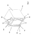
- FIG. 1 shows a running as a frame receiving body AK, which is designed essentially cuboid and in the interior of IR a in FIG. 1 not shown camera housing KG is inserted.
- the receiving body AK has on a bottom opposite to two openings ⁇ , in which the angled ends of a U-shaped spring clip FB are mounted.
- the openings ⁇ are each formed as an oblong hole, so that the ends of the spring clip FB are easily inserted in a position and held securely after pivoting of the spring clip FB in the closed position.
- FIG. 1 the open position of the closure element formed by the spring clip FB is shown.
- the spring clip FB After inserting a camera body KG in the receiving body AK the spring clip FB is pivoted into the closed position and locks the closure element ( FIG. 2 ).
- the frame-shaped receiving body AK on the top two locking lugs RN with which cooperate two parallel to the pivot axis of the spring clip FB extending locking portions VA.
- the in the pivoting direction of the spring clip FB forward facing sides of these locking lugs RN are oblique and thus facilitate the closing of the spring clip FB.
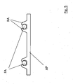
- the spring clip FB is shown separately as a component.
- the designed as a U-shaped part spring clip FB has on the two legs depending on an angled end BE, which is inserted through each one of the openings ⁇ .
- Between the with the locking lugs RN of the receiving body cooperating locking portions VA of the spring clip FB is formed to an operating bracket BB, by means of which the closing element can be pivoted resiliently via the locking lugs RN.
- the portions of the legs of the spring clip FB cooperating with the rear side of a camera housing KG set in the receptacle AK are designed as a spring area FA, which in the closed state of the spring clip exert a force acting in the insertion direction on the camera housing KG.
- the spring clip FB or its spring areas FA acts via a closure plate AP on the camera housing set in the receiving body AK.
- the end plate AP may have detent receptacles RA, in which the spring portions FA of the spring clip are engaged.
- the end plate is directly connected to the spring clip FB as a closure element, which facilitates the handling requirement when inserting a camera body with the subsequent locking of the spring clip and minimizes additional tuning work.
- the spring clip is not mounted separately, but injected in the same plastic injection process.
- the opening 10 of the recording AK shown which consists in the simplest case of a circular hole for a lens.
- the frame may also have a rectangular opening 10. Depending on the installation location, such an opening is sufficient.
- the side which is not visible in the figures and which can be described as the viewing direction of the camera or the sensor, can be made with a molded and correspondingly equipped design surfaces and hole recess, however, an extra design side with hole recess can be combined with housing AK.
- FIG. 6 schematically a grille 12 is shown, which includes several installation areas 14 by way of example.
- the installation areas constitute openings in the structure of the radiator grille, behind which a receptacle AK according to the invention is mounted.
- the installation areas are preferably in the region of the cross member 15, the radiator cover 16 or in the frame 17 of the radiator grill or above the logo or below the upper adjacent contour of the bumper or the hood.
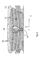
- FIGS. 7a and 7b show a solution for closing the opening 10 of the recordings, which, as not further explained, from the photographs AK the FIGS. 1 to 5 consists.
- the recording AK and the course of the radiator grille 12 can be seen.
- a flap 11 is connected to a pivot point or a pivot axis 13 on the recordings AK and is slightly open in this example in the lower area. However, the flap 11 may not completely close the opening 10, so that pointed water may drain as well.
- the recording AK should have a drain for the ingress of spray during operation.
- the housing has a drain hole AL at the lowest area, so that any accumulations of water can escape.
- the flap can be actuated mechanically or electrically, and pivotable about the articulation point or articulation axis 13.
- the optics of a camera in the x-direction or even deviate obliquely downward pushes out and thus the flap imprints. This can be done with the camera optic itself or using a cam.
- a spring can restore the closed state again.
- the flap can be taken by moving back the camera or a cam.
- a servomotor must be provided to open the flap 11.
- the receptacle is arranged behind the grille and the sensor system receives data through the grille itself or through an opening in the grille.
- the flap is guided in one or two displacement axes 20 and shifts as in FIG. 7c represented along an axis perpendicular to the vehicle longitudinal axis x, that is either laterally in the y-direction or in the z-direction.
- Alternative mounting positions are also conceivable so that the plane of the displacement takes place in any other plane of the X / Y / Z axis system.
- the flap is rectangular, but there are also round or rounded or oval shapes for the flap 11 is conceivable. Especially with a round cover is a turning away the flap around a pivot point in the plane yz the opening 10 of the recording AK easy to implement.
Description
Die Erfindung betrifft eine Aufnahmevorrichtung für elektrische Komponenten in einem Kraftfahrzeug nach der Art von Anspruch 1.The invention relates to a receiving device for electrical components in a motor vehicle according to the type of claim 1.
In modernen Kraftfahrzeugen werden zur Erfassung der Verkehrssituation elektronische Kameras verwendet, welche in der Front- und oder Heckscheibe bzw. im Bereich der Außenkarosserie angeordnet sind. Diese Kamerasysteme bestehen aus eine Optik sowie einer als Flächenchip ausgebildeten Bildaufnahmevorrichtung mit einer nachgeschalteten Elektronik, so dass die Bildsignale über eine entsprechende Verkabelung - meist über ein Koax-Kabel einer Auswerteelektronik zugeleitet werden kann.In modern motor vehicles electronic cameras are used to detect the traffic situation, which are arranged in the front and or rear window or in the region of the outer body. These camera systems consist of an optic and an image pickup device in the form of a surface chip with downstream electronics, so that the image signals can be fed via an appropriate cabling - usually via a coax cable to a transmitter.
Die beschriebenen und im KFZ-Bereich eigesetzten Kamerasysteme sind kompakt in einem Gehäuse ausgeführt, d.h. Optik, Chip sowie die direkt dem Chip zugeordnete Elektronik sind in einem einstückigen Gehäuse zusammengefasst. Diese kompakte Einheit wird dann in eine entsprechende Aufnahme am Kraftfahrzeug eingesetzt. Ein bekannter Anwendungsfall ist eine Surround-Kamera, mittels der die Außenumgebung des Fahrzeuges - insbesondere der Heckbereich - aufgenommen und auf einem Bildschirm im Innenbereich wiedergegeben wird.The camera systems described and used in the automotive field are compact in a housing, i. Optics, chip and the electronics directly assigned to the chip are combined in a one-piece housing. This compact unit is then inserted into a corresponding receptacle on the motor vehicle. A known application is a surround camera, by means of which the external environment of the vehicle - in particular the rear area - recorded and displayed on an indoor screen.
Bisherige Surround-Kameras sind meist in einem Kunststoffgehäuse untergebracht. Als fahrzeugseitige Aufnahme dient eine Öffnung, in welche das Gehäuse der Kamera eingesteckt und darin verrastet wird. Die Aufnahme bzw. das Gehäuse weisen zur Fixierung der Kamera entsprechende Rastelemente, Rastzungen, sowie Fixier- und Einführrippen auf.Previous surround cameras are usually housed in a plastic housing. As an on-vehicle recording is an opening into which the housing of the camera is inserted and locked in it. The receptacle or the housing have for fixing the camera corresponding latching elements, latching tongues, as well as fixing and insertion ribs.
Metallgehäuse von Kamerasystemen mit aufwändigerer Optik bzw. größeren Bild-Chips können in diesen bekannten Aufnahmeanordnungen nicht bzw. nicht ohne zusätzlichen Aufwand fixiert werden.Metal housing of camera systems with more complex optics or larger image chips can not in these known recording arrangements or not be fixed without additional effort.
In der
Das Dokument
Als weiterer Aspekt des Gehäuses sollte zusätzlich zur Verrastung auch der ein minimaler Schutz der Öffnung für die Sensoren vorhanden sein. Wenn die Surround-Kamera im Frontbereich des Fahrzeugs eingesetzt wird, ist sie Steinschlägen ausgesetzt. Daher ist eine Abdeckung oder Abschirmung sicherlich nützlich.As a further aspect of the housing should also be in addition to the latching a minimal protection of the opening for the sensors to be present. If the surround camera is used in the front of the vehicle, it is exposed to rockfalls. Therefore, a cover or shield is certainly useful.
Die Aufgabe der vorliegenden Erfindung besteht darin, eine Aufnahmevorrichtung für eine Sensorik, eine Elektronik, eine Antriebseinheit oder eine Kamera in gegenüber den bekannten Ausführungen verbesserter Ausführung zu schaffen.The object of the present invention is to provide a receiving device for a sensor, an electronics, a drive unit or a camera in relation to the known versions of improved design.
Diese Aufgabe wird gelöst durch die Merkmale von Anspruch 1. Weiterbildungen ergeben sich aus den Unteransprüchen.This object is achieved by the features of claim 1. Further developments will become apparent from the dependent claims.
Gemäß der Erfindung ist eine Aufnahmevorrichtung vorgesehen, bestehend aus einem als Rahmen ausgebildeten, einen Innenraum umgebenden Aufnahme, in welchen ein Gehäuse, bspw. ein Gehäuse einer Kamera einschiebbar ist, einem gelenkig mit Rahmen der Aufnahme verbundenen Verschlusselement, welches von einer die Aufnahme freigebenden Stellung in eine die Aufnahme schließenden Stellung verschwenkbar ist sowie einem dem Verschlusselement zugeordneten Fixierung, welche das Verschlusselement in der geschlossenen Position hält.According to the invention, a receiving device is provided, consisting of a housing formed as a frame, surrounding an interior, in which a housing, for example. A housing of a camera is inserted, a hingedly connected to the frame of the recording closure element, which of a recording releasing the position in a recording closing position is pivoted and a the closure member associated fixation, which holds the closure element in the closed position.
Bei dem Verschlusselement handelt es sich bevorzugt um einen Federbügel, der im Wesentlichen U-förmig bzw. W-förmig gestaltet ist und über je eine Abwinkelung an den Enden der U-Schenkel in einer Öffnung des Aufnahmerahmens gelagert ist. Der Federbügel kann so nach Einschieben des Kameragehäuses von der Offenposition in die Schließposition verschwenkt werden, in der das Kameragehäuse durch den Federdruck in dem Aufnahmerahmen gehalten und gegen vorgesehene Anschläge gedrückt wird. Insbesondere weist der Federbügel einen in Einschubrichtung (für das Kameragehäuse) federnd wirkenden Federabschnitt auf.The closure element is preferably a spring clip, which is designed substantially U-shaped or W-shaped and is mounted via a respective bend at the ends of the U-legs in an opening of the receiving frame. The spring clip can be pivoted so after insertion of the camera body from the open position to the closed position in which the camera body is held by the spring pressure in the receiving frame and pressed against provided stops. In particular, the spring clip on a in the insertion direction (for the camera body) resiliently acting spring portion.
Die Erfindung weiterbildend ist vorgesehen, dass unterschiedlich geformte Verschlusselemente und insbesondere Federbügel mit dem Aufnahmerahmen koppelbar sind. So können unterschiedlich tief ausgeführte Kameragehäuse in der Rahmenaufnahme eingestellt und darin befestigt werden.The invention further development is provided that differently shaped closure elements and in particular spring clip can be coupled to the receiving frame. Thus, camera housings of different depths can be set in the frame mount and fastened therein.
Eine Weiterbildung der Erfindung sieht vor, dass der Federbügel als Verschlusselementüber eine an die Form des Aufnahmerahmens angepasste Abschlussplatte auf das eingestellte Kameragehäuse einwirkt. Die Abschlussplatte bewirkt eine Vergleichmäßigung des Druckes des Federbügels auf das Kameragehäuse. Weiterhin ist es möglich, durch unterschiedlich tief ausgeführte Abschlussplatten eine Anpassung an unterschiedlich große Kameragehäuse vorzunehmen. Die Abschlussplatte kann zusätzlich mit dem Aufnahmerahmen zusammenwirkende Dichtelemente aufweisen, so dass die in der Aufnahmevorrichtung untergebrachte Einheit vor Witterungseinflüssen wie Staub oder Feuchtigkeit geschützt ist.A further development of the invention provides that the spring clip acts as a closure element on the adjusted camera housing via an end plate adapted to the shape of the receiving frame. The end plate causes a homogenization of the pressure of the spring clip on the camera body. Furthermore, it is possible to make an adaptation to differently sized camera body by differently deep running end plates. The end plate may additionally have cooperating with the receiving frame sealing elements, so that the unit housed in the receiving device is protected from the weather, such as dust or moisture.
Eine weitere Ausführungsform sieht eine Klappe zum Abdeckung der Sichtöffnung der erfindungsgemäßen Aufnahme vor, wodurch die Aufnahme und das darin befindliche Gerät vor Steinschlägen geschützt werden.A further embodiment provides a flap for covering the viewing opening of the recording according to the invention, whereby the recording and the device therein are protected from rockfalls.
Vorteilhafterweise ist die Klappe dabei je nach Einbauort gelenkig mit der Aufnahme selbst oder aber mit einem Einbauort am Fahrzeug selbst, vorzugsweise am Kühlergrill verbunden.Advantageously, the flap is articulated depending on the location with the recording itself or with a mounting location on the vehicle itself, preferably connected to the grille.
Des Weiteren erfolgt die Erläuterung von Ausführungsbeispielen der Erfindung an Hand der Zeichnungen.Furthermore, the explanation of embodiments of the invention with reference to the drawings.
Nach Einschieben eines Kameragehäuses KG in den Aufnahmekörper AK wird der Federbügel FB in die Schließposition verschwenkt und das Verschlusselement verriegelt (
In
Bei der Ausführungsform nach
In einer weiteren vorteilhaften Ausführungsform wird der Federbügel nicht getrennt montiert, sondern gleich im Kunststoffspritzvorgang eingespritzt.In a further advantageous embodiment, the spring clip is not mounted separately, but injected in the same plastic injection process.
In keiner der
Die Seite, die in den Figuren nicht sichtbar ist und die man als Sichtrichtung der Kamera oder des Sensors bezeichnen kann, kann mit eine angeformten und entsprechend ausgestatteten Designflächen und Lochaussparung hergestellt sein, jedoch kann auch ein extra Designseite mit Lochaussparung mit Gehäuse AK vereint werden.The side, which is not visible in the figures and which can be described as the viewing direction of the camera or the sensor, can be made with a molded and correspondingly equipped design surfaces and hole recess, however, an extra design side with hole recess can be combined with housing AK.
In
Da die Sensorik speziell bei einem Einbau im Bereich des Kühlergrills Steinschlägen ausgesetzt ist, ist eine Abdeckung der Öffnung 10 sinnvoll.Since the sensor is exposed to rockfalls especially when installed in the grille area, a cover of the
Die
In einer vollständig zu schließenden Variante wird zusätzlich durch den Einbau von Dichtungen ein guter Schutz vor Spritzwasser und Vereisung erreicht, allerdings sollten dann die Aufnahme AK einen Ablauf für das während des Betriebs eindringenden Spritzwasser aufweisen. Das Gehäuse weist eine Ablaufloch AL am tiefsten Bereich auf, damit etwaige Wasseransammlungen entweichen können.In a completely closed variant, a good protection against splash water and icing is additionally achieved by the installation of seals, however, then the recording AK should have a drain for the ingress of spray during operation. The housing has a drain hole AL at the lowest area, so that any accumulations of water can escape.
Die Klappe ist mechanisch oder elektrisch betätigbar, und um den Anlenkpunkt oder Anlenkachse 13 verschwenkbar. Bei der mechanischen Lösung ist es vorstellbar, dass sich die Optik einer Kamera in x-Richtung oder auch davon abweichen schräg nach unten herausschiebt und dadurch die Klappe aufdrückt. Das kann mit der Kameraoptik selbst oder unter Verwendung einer Nocke geschehen. Zum Verschluß der Klappe kann eine Feder wieder den geschlossenen Zustand wieder herstellen. Alternativ dazu kann die Klappe durch Zurückfahren der Kamera bzw eines Nocken mitgenommen.The flap can be actuated mechanically or electrically, and pivotable about the articulation point or
In einer elektrischen Variante muss ein Stellmotor vorgesehen werden, um die Klappe 11 zu öffnen. In
In der Ausführung nach
Als weitere alternative Ausführungsform wird die Klappe in einer oder zwei Verschiebeachsen 20 geführt und verschiebt sich wie in
Es sind aber auch alternative Achsenlagen für die Verschiebeachse 20 denkbar.But there are also alternative axial positions for the
Im Beispiel ist die Klappe rechteckig, es sind aber auch runde oder gerundete oder ovale Formen für die Klappe 11 denkbar. Gerade bei einer runden Abdeckung ist ein Wegdrehen der Klappe um einen Anlenkpunkt in der Ebene y-z der Öffnung 10 der Aufnahme AK einfach umzusetzen.In the example, the flap is rectangular, but there are also round or rounded or oval shapes for the
- AKAK
- Aufnahme, Kameraaufnahme, AufnahmerahmenRecording, camera recording, recording frame
- IRIR
- Innenrauminner space
- FBFB
- Federbügelspring clip
- ÖÖ
- Öffnung (Langloch)Opening (slot)
- RNRN
- Rastnaselocking lug
- VAVA
- Verriegelungsabschnittlocking section
- FAFA
- Federabschnittspring section
- BEBE
- abgewinkeltes Endeangled end
- BBBB
- Betätigungsbügelactuating bow
- APAP
- AbschlussplatteEnd plate
- RARA
- Rastaufnahmelatching receptacle
- 1010
- Öffnungopening
- 1111
- Klappeflap
- 1212
- Kühlergrillradiator grill
- 1313
- Anlenkpunkt oder AnlenkachseArticulation point or articulation axis
- 1414
- Einbaubereicheinstallation areas
- 1515
- Querträgercrossbeam
- 1616
- Kühlerabdeckungradiator cover
- 1717
- Rahmenframe
- 2020
- Verschiebeachsedisplacement axis
Claims (12)
- Holding device for carrying and fixing a housing for a sensor system and/or an electronic system, a drive unit or a camera in or on a motor vehicle, comprising a holder (AK) configured as a frame surrounding an interior (IR), into which the housing (KG) can be inserted, a spring clamp (FB) connected to the frame of the holder (AK) in an articulated manner, said spring clamp being pivotable from a position in which the interior (IR) of the holder (AK) is released into a position in which the interior (IR) of the holder (AK) is closed, and also a fixing assigned to the spring clamp (FB), which holds the spring clamp (FB) in the closed position, and in that the spring clamp is configured as a U-shaped or W-shaped wire bracket, which is suspended in an articulated manner in openings (Ö) in the holder (AK) via angled ends (BE) of its legs, the locking element configured as a spring clamp (FB) being injected with angled ends (BE) in the holder (AK).
- Holding device according to Claim 1, characterized in that the locking element is configured as a spring clamp (FB) which is connected to the holder (AK) in an articulated manner by at least one angled end.
- Holding device according to Claim 1, characterized in that the locking element (FB) acts directly on a rear side of a housing (KG) positioned in the holder (AK).
- Holding device according to Claim 1, characterized in that the locking element (FB) acts on the housing (KG) via an end plate (AP) located between the locking element (FB) and the rear side of the positioned housing (KG).
- Holding device according to Claim 1, characterized in that the end plate (AP) exhibits sealing elements acting together with the holder (AK).
- Holding device according to Claims 2 to 4, characterized in that the locking element configured as a spring clamp (FB) exhibits a locking section (VA) working together with a latching lug (RN) on the holder (AK) as the fixing.
- Holding device according to Claims 2 to 4, characterized in that the locking element configured as a spring clamp (FB) exhibits a spring section (FA) acting in the insertion direction of the housing.
- Holding device according to one of the preceding claims, characterized in that the holder (AK) exhibits a closable opening (10) in the viewing direction of the sensor system.
- Holding device according to Claim 8, characterized in that the closable opening (10) is provided with a pivotable and/or displaceable flap (11).
- Holding device according to Claim 9, characterized in that the pivotable and/or displaceable flap (11) is attached to a pivot point or a pivot plane (13) of the holders (AK).
- Holding device according to Claim 9, characterized in that the holder is attached to a radiator grill (12) and the pivotable and/or displaceable flap (11) is attached to a pivot point or a pivot plane (13') of the radiator grill.
- Holding device according to Claim 1, characterized in that the holder (AK) exhibits a run-off hole (AL) for water.
Applications Claiming Priority (1)
| Application Number | Priority Date | Filing Date | Title |
|---|---|---|---|
| DE201210011596 DE102012011596B3 (en) | 2012-06-13 | 2012-06-13 | cradle |
Publications (2)
| Publication Number | Publication Date |
|---|---|
| EP2674331A1 EP2674331A1 (en) | 2013-12-18 |
| EP2674331B1 true EP2674331B1 (en) | 2015-03-11 |
Family
ID=48092778
Family Applications (1)
| Application Number | Title | Priority Date | Filing Date |
|---|---|---|---|
| EP20130163495 Not-in-force EP2674331B1 (en) | 2012-06-13 | 2013-04-12 | Holding device |
Country Status (5)
| Country | Link |
|---|---|
| US (1) | US9056586B2 (en) |
| EP (1) | EP2674331B1 (en) |
| CN (1) | CN103481836B (en) |
| DE (1) | DE102012011596B3 (en) |
| MX (1) | MX337840B (en) |
Families Citing this family (11)
| Publication number | Priority date | Publication date | Assignee | Title |
|---|---|---|---|---|
| DE102011108594A1 (en) * | 2011-07-26 | 2013-01-31 | Daimler Ag | Fastening arrangement of a sensor element on a fastening element of a motor vehicle |
| JP1516783S (en) * | 2014-03-07 | 2015-02-09 | ||
| JP6202028B2 (en) * | 2015-03-24 | 2017-09-27 | トヨタ自動車株式会社 | Arrangement structure of surrounding information detection sensor and autonomous driving vehicle |
| US10144424B2 (en) * | 2015-04-09 | 2018-12-04 | Toyota Jidosha Kabushiki Kaisha | Arrangement structure for vicinity information detection sensor |
| EP3173290B1 (en) * | 2015-11-26 | 2019-01-30 | Continental Automotive GmbH | Camera bracket with metal wire spring |
| EP3173289B1 (en) * | 2015-11-26 | 2018-09-19 | Continental Automotive GmbH | Camera bracket with metal wire spring |
| EP3466767A1 (en) * | 2017-10-05 | 2019-04-10 | Veoneer Sweden AB | Attachment for a camera module in a camera housing and a camera module |
| EP3566907B1 (en) * | 2018-05-08 | 2021-03-17 | Volvo Car Corporation | Bracket for fixating a housing comprising a camera |
| CN114667205A (en) * | 2019-11-26 | 2022-06-24 | 米沃奇电动工具公司 | Fixed compartment for modular storage |
| EP4140822A1 (en) * | 2021-08-25 | 2023-03-01 | Bayerische Motoren Werke Aktiengesellschaft | Mounting device for a perimeter sensor and sensor assembly system for a vehicle |
| DE102022208409A1 (en) | 2022-08-12 | 2024-02-15 | Volkswagen Aktiengesellschaft | Holding device for holding a sensor on a vehicle component and vehicle component with a holding device |
Family Cites Families (63)
| Publication number | Priority date | Publication date | Assignee | Title |
|---|---|---|---|---|
| US3598297A (en) * | 1969-10-03 | 1971-08-10 | Irene P Welch | Automobile litter bag support |
| US3912055A (en) * | 1974-03-18 | 1975-10-14 | Robert J Malooly | Luggage case having hinged lid with auxiliary access door to file compartment therein |
| GB1494679A (en) * | 1974-03-28 | 1977-12-07 | Siemens Ag | Housings for telecommunications equipment or the like |
| US4309065A (en) * | 1979-04-16 | 1982-01-05 | Pappas Peter R | Security enclosure for handguns |
| JPS6021086B2 (en) * | 1979-04-27 | 1985-05-25 | キヤタピラ−三菱株式会社 | earthmoving vehicle |
| US4228936A (en) * | 1979-08-15 | 1980-10-21 | Rife Orin S | Tire and tool carrier |
| US4889377A (en) * | 1987-08-14 | 1989-12-26 | Roger Hughes | Vehicle storage system |
| US4893112A (en) * | 1987-11-23 | 1990-01-09 | Hatcher Howard R | Brake light and radar detection device |
| US4976450A (en) * | 1988-02-10 | 1990-12-11 | Ellefson Laurence M | Mobile tool chest with horizontal pivotal trays |
| JPH02138992U (en) * | 1989-04-22 | 1990-11-20 | ||
| US5161700A (en) * | 1991-01-28 | 1992-11-10 | Prince Corporation | Adjustable storage system for a vehicle |
| US5100188A (en) * | 1991-03-15 | 1992-03-31 | Chrysler Corporation | Vehicle grille mounting apparatus |
| US5328066A (en) * | 1991-07-25 | 1994-07-12 | Cappuccio Louis W | Cart device and method |
| US5395019A (en) * | 1991-12-04 | 1995-03-07 | Christensen; David | Portable utility container with latch and mount |
| US5287971A (en) * | 1992-06-25 | 1994-02-22 | Isidore Dorman | Rack for supporting loaded plastic grocery bags |
| US5299722A (en) * | 1993-01-21 | 1994-04-05 | Cheney Dale S | Double lid truck storage box |
| US5484092A (en) * | 1993-01-21 | 1996-01-16 | Cheney; Dale S. | Vehicle storage box with double secured compartments |
| US5619036A (en) * | 1994-04-12 | 1997-04-08 | Hughes Electronics | Low cost night vision camera for vehicles and mounting thereof |
| US5628439A (en) * | 1995-12-04 | 1997-05-13 | O'hara; Timothy P. | Portable desk and file holder for use in a seat |
| US5875948A (en) * | 1996-08-30 | 1999-03-02 | Randall C. Hansen | Truck box with end-mounted paddle handle and latching mechanism therefor |
| US5881584A (en) * | 1996-11-13 | 1999-03-16 | Brunoski; Thomas T. | Portable shockproof locking mechanism |
| US5967392A (en) * | 1997-04-22 | 1999-10-19 | Penda Corporation | Cargo bed utility box |
| JP3419675B2 (en) * | 1998-02-10 | 2003-06-23 | 三菱電機株式会社 | In-vehicle radio radar equipment |
| US6246323B1 (en) * | 1998-03-18 | 2001-06-12 | Trevor A. Fischbach | Method and system for tracking a vehicle |
| US5979724A (en) * | 1998-09-01 | 1999-11-09 | Command Audio Corporation | Automobile universal dashboard mounting apparatus |
| US6318773B2 (en) * | 1999-02-02 | 2001-11-20 | Ron D. Storer | Push bar mounting system |
| JP3885459B2 (en) * | 2000-04-07 | 2007-02-21 | いすゞ自動車株式会社 | Ventilating muffler unit and ventilated muffler |
| US20030023855A1 (en) * | 2001-06-29 | 2003-01-30 | Keogh Kyle Dana | High security storage unit and biometric entry system |
| US20100253519A1 (en) * | 2001-12-28 | 2010-10-07 | Private Pallet Security Systems, Llc | Underdeck carrier system for mobile containers for segregating product types in common shipment |
| US20030142503A1 (en) * | 2002-01-30 | 2003-07-31 | Ford Global Technologies, Inc. | Pedestrian protection headlamp |
| AU2003247148A1 (en) * | 2002-08-05 | 2004-02-23 | Elbit Systems Ltd. | Vehicle mounted night vision imaging system and method |
| AU2002951987A0 (en) * | 2002-10-09 | 2002-10-31 | Lokaway Pty. Ltd. | Security door and frame construction |
| ATE503071T1 (en) * | 2002-10-09 | 2011-04-15 | Lokaway Pty Ltd | SECURITY DOOR AND FRAME CONSTRUCTION |
| DE10333036A1 (en) * | 2003-07-21 | 2005-02-10 | Hella Kgaa Hueck & Co. | lighting device |
| DE10337751B3 (en) * | 2003-08-07 | 2005-03-17 | Decoma (Germany) Gmbh | Grille for mounting in a grille assembly and method for its production |
| US6966593B2 (en) * | 2003-12-22 | 2005-11-22 | Nissan Technical Center North America, Inc. | Vehicle side panel storage box assembly |
| US7878472B2 (en) * | 2004-10-12 | 2011-02-01 | Pierce Manufacturing Inc. | Auto-locking holder apparatus |
| US7665642B2 (en) * | 2004-11-29 | 2010-02-23 | Richard Abbate | Portable activity case with fold-out table |
| US7153092B1 (en) * | 2004-12-28 | 2006-12-26 | Kendrick Randolph | Automotive grill incorporating rotatable turbine structures |
| US7942447B2 (en) * | 2004-12-30 | 2011-05-17 | American Off-Road Technologies, Llc | Frame design for reduced-size vehicle |
| US7980436B2 (en) * | 2005-07-01 | 2011-07-19 | Yakima Products, Inc. | Cargo box gear mounting assembly |
| US20070246495A1 (en) * | 2006-01-27 | 2007-10-25 | Kalispel Case Line | Storage system for transporting, protecting and storing valuable property |
| US7455351B2 (en) * | 2006-02-15 | 2008-11-25 | Mazda Motor Corporation | Vehicle front end structure |
| US20070216768A1 (en) * | 2006-03-14 | 2007-09-20 | Ford Global Technologies, Llc | Device and method for outwardly looking ir camera mounted inside vehicles particularly suited for pre-crash sensing and pedestrian detection |
| DE102006061308A1 (en) * | 2006-12-22 | 2008-06-26 | Leopold Kostal Gmbh & Co. Kg | bracket |
| FR2912710A1 (en) * | 2007-02-15 | 2008-08-22 | Renault Sas | Outer grid e.g. cowl vent grille, device for motor vehicle, has plastic gauze whose meshing is thinner than that of grid and arranged along internal surface of grid, where surface has grooves forming fixation zone between grid and gauze |
| CN201062021Y (en) * | 2007-07-19 | 2008-05-21 | 合盈光电科技股份有限公司 | Clamp-fastening type automobile video system |
| US8204245B2 (en) * | 2007-10-31 | 2012-06-19 | Lund Industries, Inc. | Bumper with speaker |
| DE102008044840A1 (en) * | 2008-08-28 | 2010-03-04 | Leopold Kostal Gmbh & Co. Kg | Sensor arrangement for a motor vehicle |
| US7762601B2 (en) * | 2008-08-29 | 2010-07-27 | Nissan Technical Center North America, Inc. | Vehicle container interface |
| US8215688B2 (en) * | 2008-10-15 | 2012-07-10 | Johnson Controls Technology Company | Vehicle floor console |
| US20100264180A1 (en) * | 2008-12-31 | 2010-10-21 | Nii-Akwei Allotey | Collapsible Tool/Utility Box |
| DE102009011614B4 (en) * | 2009-03-04 | 2021-01-07 | Kostal Automobil Elektrik Gmbh & Co. Kg | Sensor arrangement for a motor vehicle |
| US20110006553A1 (en) * | 2009-07-07 | 2011-01-13 | Warn Industries, Inc. | Winch Carrier and Grille Guard Mounting System |
| US8220849B2 (en) * | 2009-08-27 | 2012-07-17 | Beaird Iii Robert L | Device for mounting an accessory on a motor vehicle |
| US8689591B2 (en) * | 2009-12-23 | 2014-04-08 | 9G Products, Inc. | Personal property safe |
| USD702620S1 (en) * | 2010-02-25 | 2014-04-15 | 1541689 Ontario Inc. | Bracket |
| US8631982B2 (en) * | 2010-02-26 | 2014-01-21 | Robert Anthony Vicente | Safe attached to the hitch of a vehicle |
| US8833313B2 (en) * | 2010-05-17 | 2014-09-16 | GM Global Technology Operations LLC | Grille airflow shutter system with discrete shutter control |
| US20130025511A1 (en) * | 2011-07-25 | 2013-01-31 | Timothy Eugene Maxwell | Handgun safe |
| US8922655B2 (en) * | 2011-10-28 | 2014-12-30 | Nissan North America, Inc. | Vehicle front grille assembly |
| US9016643B2 (en) * | 2013-05-21 | 2015-04-28 | David Sterling | Apparatus for mounting accessory equipment to tow hooks |
| JP2015025770A (en) * | 2013-07-29 | 2015-02-05 | 株式会社リコー | Detection device, vehicle |
-
2012
- 2012-06-13 DE DE201210011596 patent/DE102012011596B3/en not_active Expired - Fee Related
-
2013
- 2013-04-12 EP EP20130163495 patent/EP2674331B1/en not_active Not-in-force
- 2013-06-13 MX MX2013006779A patent/MX337840B/en active IP Right Grant
- 2013-06-13 US US13/916,750 patent/US9056586B2/en not_active Expired - Fee Related
- 2013-06-13 CN CN201310232594.4A patent/CN103481836B/en not_active Expired - Fee Related
Also Published As
| Publication number | Publication date |
|---|---|
| EP2674331A1 (en) | 2013-12-18 |
| MX337840B (en) | 2016-03-22 |
| US9056586B2 (en) | 2015-06-16 |
| CN103481836B (en) | 2016-11-23 |
| DE102012011596B3 (en) | 2013-07-04 |
| US20130334268A1 (en) | 2013-12-19 |
| CN103481836A (en) | 2014-01-01 |
| MX2013006779A (en) | 2014-03-24 |
Similar Documents
| Publication | Publication Date | Title |
|---|---|---|
| EP2674331B1 (en) | Holding device | |
| EP2616282B1 (en) | Camera arrangement for a vehicle and method for installing a camera arrangement in a vehicle | |
| EP1760826B1 (en) | Mounting of a roof antenna by introducing a tool through an opening of antenna tail holder on the housing of the antenna | |
| EP2673169B1 (en) | Camera arrangement for a vehicle and method for installation | |
| DE4334721B4 (en) | Headlights for vehicles | |
| EP3526080B1 (en) | Camera module | |
| DE102011108392A1 (en) | Vehicle with a roof console | |
| DE102018213818B4 (en) | Holding device for an external attachment part of a motor vehicle | |
| DE102014224860A1 (en) | Lens Hood | |
| DE102019101861A1 (en) | Device for a motor vehicle | |
| DE102010026268A1 (en) | Vehicle, has camera arranged in radiator cowl and moved between rest position and operating position by swivel mechanism, where camera is extendable from radiator cowl in plane and visible from outside in operating position | |
| DE102018121600A1 (en) | Rear camera holder | |
| DE102019102298A1 (en) | Roof antenna of a vehicle with a reversing camera | |
| DE10144166A1 (en) | Lock for vehicle door has lock housing and lock cover formed in one piece therewith through film hinge or similar | |
| DE102010008214A1 (en) | Camera device for motor vehicle, has camera, which is adjustably arranged between non-operating position and operating position | |
| DE102012218388B4 (en) | apparatusaccommodating | |
| DE102012024274A1 (en) | Holding device for receiving and fixing mirror of mirror device to vehicle window of motor vehicle, has one receptacle for receiving mirror and another receptacle for receiving electrical device | |
| DE10103402A1 (en) | Exterior rear view mirror of a motor vehicle | |
| DE102018205838B4 (en) | Motor vehicle turn signal arm and turn signal assembly | |
| DE202010003623U1 (en) | Contactor arrangement for a trailer hitch | |
| DE102016102138A1 (en) | Mounting frame for attaching a functional unit to a device wall | |
| DE102012017942A1 (en) | Holding device for holding a sensor device on a window of a motor vehicle | |
| EP1504967B1 (en) | Adjustable sensor support | |
| DE102013015336A1 (en) | Arrangement structure for arrangement of electronic unit in bumper of motor vehicle, has housing comprising lid which defines receiving space for electronic unit, such that lid is coupled with one side wall over hinge | |
| DE102018008105B4 (en) | Motor vehicle emblem with integrated sensor and cleaning device |
Legal Events
| Date | Code | Title | Description |
|---|---|---|---|
| PUAI | Public reference made under article 153(3) epc to a published international application that has entered the european phase |
Free format text: ORIGINAL CODE: 0009012 |
|
| 17P | Request for examination filed |
Effective date: 20130819 |
|
| AK | Designated contracting states |
Kind code of ref document: A1 Designated state(s): AL AT BE BG CH CY CZ DE DK EE ES FI FR GB GR HR HU IE IS IT LI LT LU LV MC MK MT NL NO PL PT RO RS SE SI SK SM TR |
|
| AX | Request for extension of the european patent |
Extension state: BA ME |
|
| GRAP | Despatch of communication of intention to grant a patent |
Free format text: ORIGINAL CODE: EPIDOSNIGR1 |
|
| RIC1 | Information provided on ipc code assigned before grant |
Ipc: B60R 16/023 20060101AFI20141111BHEP Ipc: B60R 11/02 20060101ALI20141111BHEP Ipc: B60R 11/04 20060101ALI20141111BHEP Ipc: B60R 11/00 20060101ALN20141111BHEP Ipc: G01D 11/30 20060101ALI20141111BHEP |
|
| RIC1 | Information provided on ipc code assigned before grant |
Ipc: B60R 11/00 20060101ALN20141118BHEP Ipc: B60R 16/023 20060101AFI20141118BHEP Ipc: B60R 11/02 20060101ALI20141118BHEP Ipc: G01D 11/30 20060101ALI20141118BHEP Ipc: B60R 11/04 20060101ALI20141118BHEP |
|
| INTG | Intention to grant announced |
Effective date: 20141202 |
|
| GRAS | Grant fee paid |
Free format text: ORIGINAL CODE: EPIDOSNIGR3 |
|
| GRAA | (expected) grant |
Free format text: ORIGINAL CODE: 0009210 |
|
| AK | Designated contracting states |
Kind code of ref document: B1 Designated state(s): AL AT BE BG CH CY CZ DE DK EE ES FI FR GB GR HR HU IE IS IT LI LT LU LV MC MK MT NL NO PL PT RO RS SE SI SK SM TR |
|
| REG | Reference to a national code |
Ref country code: GB Ref legal event code: FG4D Free format text: NOT ENGLISH |
|
| REG | Reference to a national code |
Ref country code: CH Ref legal event code: EP |
|
| REG | Reference to a national code |
Ref country code: IE Ref legal event code: FG4D Free format text: LANGUAGE OF EP DOCUMENT: GERMAN |
|
| REG | Reference to a national code |
Ref country code: AT Ref legal event code: REF Ref document number: 715124 Country of ref document: AT Kind code of ref document: T Effective date: 20150415 |
|
| REG | Reference to a national code |
Ref country code: DE Ref legal event code: R096 Ref document number: 502013000440 Country of ref document: DE Effective date: 20150416 |
|
| REG | Reference to a national code |
Ref country code: NL Ref legal event code: VDEP Effective date: 20150311 |
|
| REG | Reference to a national code |
Ref country code: NL Ref legal event code: VDEP Effective date: 20150311 |
|
| PG25 | Lapsed in a contracting state [announced via postgrant information from national office to epo] |
Ref country code: FI Free format text: LAPSE BECAUSE OF FAILURE TO SUBMIT A TRANSLATION OF THE DESCRIPTION OR TO PAY THE FEE WITHIN THE PRESCRIBED TIME-LIMIT Effective date: 20150311 Ref country code: LT Free format text: LAPSE BECAUSE OF FAILURE TO SUBMIT A TRANSLATION OF THE DESCRIPTION OR TO PAY THE FEE WITHIN THE PRESCRIBED TIME-LIMIT Effective date: 20150311 Ref country code: NO Free format text: LAPSE BECAUSE OF FAILURE TO SUBMIT A TRANSLATION OF THE DESCRIPTION OR TO PAY THE FEE WITHIN THE PRESCRIBED TIME-LIMIT Effective date: 20150611 Ref country code: HR Free format text: LAPSE BECAUSE OF FAILURE TO SUBMIT A TRANSLATION OF THE DESCRIPTION OR TO PAY THE FEE WITHIN THE PRESCRIBED TIME-LIMIT Effective date: 20150311 Ref country code: ES Free format text: LAPSE BECAUSE OF FAILURE TO SUBMIT A TRANSLATION OF THE DESCRIPTION OR TO PAY THE FEE WITHIN THE PRESCRIBED TIME-LIMIT Effective date: 20150311 Ref country code: SE Free format text: LAPSE BECAUSE OF FAILURE TO SUBMIT A TRANSLATION OF THE DESCRIPTION OR TO PAY THE FEE WITHIN THE PRESCRIBED TIME-LIMIT Effective date: 20150311 |
|
| REG | Reference to a national code |
Ref country code: LT Ref legal event code: MG4D |
|
| PG25 | Lapsed in a contracting state [announced via postgrant information from national office to epo] |
Ref country code: RS Free format text: LAPSE BECAUSE OF FAILURE TO SUBMIT A TRANSLATION OF THE DESCRIPTION OR TO PAY THE FEE WITHIN THE PRESCRIBED TIME-LIMIT Effective date: 20150311 Ref country code: LV Free format text: LAPSE BECAUSE OF FAILURE TO SUBMIT A TRANSLATION OF THE DESCRIPTION OR TO PAY THE FEE WITHIN THE PRESCRIBED TIME-LIMIT Effective date: 20150311 Ref country code: GR Free format text: LAPSE BECAUSE OF FAILURE TO SUBMIT A TRANSLATION OF THE DESCRIPTION OR TO PAY THE FEE WITHIN THE PRESCRIBED TIME-LIMIT Effective date: 20150612 |
|
| PG25 | Lapsed in a contracting state [announced via postgrant information from national office to epo] |
Ref country code: NL Free format text: LAPSE BECAUSE OF FAILURE TO SUBMIT A TRANSLATION OF THE DESCRIPTION OR TO PAY THE FEE WITHIN THE PRESCRIBED TIME-LIMIT Effective date: 20150311 |
|
| PG25 | Lapsed in a contracting state [announced via postgrant information from national office to epo] |
Ref country code: CZ Free format text: LAPSE BECAUSE OF FAILURE TO SUBMIT A TRANSLATION OF THE DESCRIPTION OR TO PAY THE FEE WITHIN THE PRESCRIBED TIME-LIMIT Effective date: 20150311 Ref country code: RO Free format text: LAPSE BECAUSE OF FAILURE TO SUBMIT A TRANSLATION OF THE DESCRIPTION OR TO PAY THE FEE WITHIN THE PRESCRIBED TIME-LIMIT Effective date: 20150311 Ref country code: EE Free format text: LAPSE BECAUSE OF FAILURE TO SUBMIT A TRANSLATION OF THE DESCRIPTION OR TO PAY THE FEE WITHIN THE PRESCRIBED TIME-LIMIT Effective date: 20150311 Ref country code: SK Free format text: LAPSE BECAUSE OF FAILURE TO SUBMIT A TRANSLATION OF THE DESCRIPTION OR TO PAY THE FEE WITHIN THE PRESCRIBED TIME-LIMIT Effective date: 20150311 Ref country code: PT Free format text: LAPSE BECAUSE OF FAILURE TO SUBMIT A TRANSLATION OF THE DESCRIPTION OR TO PAY THE FEE WITHIN THE PRESCRIBED TIME-LIMIT Effective date: 20150713 |
|
| PG25 | Lapsed in a contracting state [announced via postgrant information from national office to epo] |
Ref country code: IS Free format text: LAPSE BECAUSE OF FAILURE TO SUBMIT A TRANSLATION OF THE DESCRIPTION OR TO PAY THE FEE WITHIN THE PRESCRIBED TIME-LIMIT Effective date: 20150711 Ref country code: PL Free format text: LAPSE BECAUSE OF FAILURE TO SUBMIT A TRANSLATION OF THE DESCRIPTION OR TO PAY THE FEE WITHIN THE PRESCRIBED TIME-LIMIT Effective date: 20150311 Ref country code: MC Free format text: LAPSE BECAUSE OF FAILURE TO SUBMIT A TRANSLATION OF THE DESCRIPTION OR TO PAY THE FEE WITHIN THE PRESCRIBED TIME-LIMIT Effective date: 20150311 |
|
| REG | Reference to a national code |
Ref country code: DE Ref legal event code: R097 Ref document number: 502013000440 Country of ref document: DE |
|
| PG25 | Lapsed in a contracting state [announced via postgrant information from national office to epo] |
Ref country code: IT Free format text: LAPSE BECAUSE OF FAILURE TO SUBMIT A TRANSLATION OF THE DESCRIPTION OR TO PAY THE FEE WITHIN THE PRESCRIBED TIME-LIMIT Effective date: 20150311 |
|
| PLBE | No opposition filed within time limit |
Free format text: ORIGINAL CODE: 0009261 |
|
| STAA | Information on the status of an ep patent application or granted ep patent |
Free format text: STATUS: NO OPPOSITION FILED WITHIN TIME LIMIT |
|
| REG | Reference to a national code |
Ref country code: IE Ref legal event code: MM4A |
|
| PG25 | Lapsed in a contracting state [announced via postgrant information from national office to epo] |
Ref country code: DK Free format text: LAPSE BECAUSE OF FAILURE TO SUBMIT A TRANSLATION OF THE DESCRIPTION OR TO PAY THE FEE WITHIN THE PRESCRIBED TIME-LIMIT Effective date: 20150311 |
|
| 26N | No opposition filed |
Effective date: 20151214 |
|
| PG25 | Lapsed in a contracting state [announced via postgrant information from national office to epo] |
Ref country code: SI Free format text: LAPSE BECAUSE OF FAILURE TO SUBMIT A TRANSLATION OF THE DESCRIPTION OR TO PAY THE FEE WITHIN THE PRESCRIBED TIME-LIMIT Effective date: 20150311 |
|
| REG | Reference to a national code |
Ref country code: FR Ref legal event code: PLFP Year of fee payment: 4 |
|
| PG25 | Lapsed in a contracting state [announced via postgrant information from national office to epo] |
Ref country code: IE Free format text: LAPSE BECAUSE OF NON-PAYMENT OF DUE FEES Effective date: 20150412 |
|
| REG | Reference to a national code |
Ref country code: CH Ref legal event code: PL |
|
| PG25 | Lapsed in a contracting state [announced via postgrant information from national office to epo] |
Ref country code: MT Free format text: LAPSE BECAUSE OF FAILURE TO SUBMIT A TRANSLATION OF THE DESCRIPTION OR TO PAY THE FEE WITHIN THE PRESCRIBED TIME-LIMIT Effective date: 20150311 |
|
| PG25 | Lapsed in a contracting state [announced via postgrant information from national office to epo] |
Ref country code: LI Free format text: LAPSE BECAUSE OF NON-PAYMENT OF DUE FEES Effective date: 20160430 Ref country code: CH Free format text: LAPSE BECAUSE OF NON-PAYMENT OF DUE FEES Effective date: 20160430 |
|
| REG | Reference to a national code |
Ref country code: DE Ref legal event code: R082 Ref document number: 502013000440 Country of ref document: DE Representative=s name: RAUSCH, GABRIELE, DIPL.-PHYS. DR.RER.NAT., DE Ref country code: DE Ref legal event code: R081 Ref document number: 502013000440 Country of ref document: DE Owner name: MAGNA EXTERIORS (GERMANY) GMBH, DE Free format text: FORMER OWNER: DECOMA (GERMANY) GMBH, 66280 SULZBACH, DE |
|
| REG | Reference to a national code |
Ref country code: FR Ref legal event code: PLFP Year of fee payment: 5 |
|
| PG25 | Lapsed in a contracting state [announced via postgrant information from national office to epo] |
Ref country code: BG Free format text: LAPSE BECAUSE OF FAILURE TO SUBMIT A TRANSLATION OF THE DESCRIPTION OR TO PAY THE FEE WITHIN THE PRESCRIBED TIME-LIMIT Effective date: 20150311 Ref country code: HU Free format text: LAPSE BECAUSE OF FAILURE TO SUBMIT A TRANSLATION OF THE DESCRIPTION OR TO PAY THE FEE WITHIN THE PRESCRIBED TIME-LIMIT; INVALID AB INITIO Effective date: 20130412 |
|
| PG25 | Lapsed in a contracting state [announced via postgrant information from national office to epo] |
Ref country code: CY Free format text: LAPSE BECAUSE OF FAILURE TO SUBMIT A TRANSLATION OF THE DESCRIPTION OR TO PAY THE FEE WITHIN THE PRESCRIBED TIME-LIMIT Effective date: 20150311 |
|
| PG25 | Lapsed in a contracting state [announced via postgrant information from national office to epo] |
Ref country code: BE Free format text: LAPSE BECAUSE OF NON-PAYMENT OF DUE FEES Effective date: 20150430 |
|
| PG25 | Lapsed in a contracting state [announced via postgrant information from national office to epo] |
Ref country code: TR Free format text: LAPSE BECAUSE OF FAILURE TO SUBMIT A TRANSLATION OF THE DESCRIPTION OR TO PAY THE FEE WITHIN THE PRESCRIBED TIME-LIMIT Effective date: 20150311 |
|
| PG25 | Lapsed in a contracting state [announced via postgrant information from national office to epo] |
Ref country code: LU Free format text: LAPSE BECAUSE OF NON-PAYMENT OF DUE FEES Effective date: 20150412 |
|
| REG | Reference to a national code |
Ref country code: FR Ref legal event code: PLFP Year of fee payment: 6 |
|
| PG25 | Lapsed in a contracting state [announced via postgrant information from national office to epo] |
Ref country code: SM Free format text: LAPSE BECAUSE OF FAILURE TO SUBMIT A TRANSLATION OF THE DESCRIPTION OR TO PAY THE FEE WITHIN THE PRESCRIBED TIME-LIMIT Effective date: 20150311 |
|
| PG25 | Lapsed in a contracting state [announced via postgrant information from national office to epo] |
Ref country code: MK Free format text: LAPSE BECAUSE OF FAILURE TO SUBMIT A TRANSLATION OF THE DESCRIPTION OR TO PAY THE FEE WITHIN THE PRESCRIBED TIME-LIMIT Effective date: 20150311 |
|
| PG25 | Lapsed in a contracting state [announced via postgrant information from national office to epo] |
Ref country code: AL Free format text: LAPSE BECAUSE OF FAILURE TO SUBMIT A TRANSLATION OF THE DESCRIPTION OR TO PAY THE FEE WITHIN THE PRESCRIBED TIME-LIMIT Effective date: 20150311 |
|
| REG | Reference to a national code |
Ref country code: AT Ref legal event code: MM01 Ref document number: 715124 Country of ref document: AT Kind code of ref document: T Effective date: 20180412 |
|
| PG25 | Lapsed in a contracting state [announced via postgrant information from national office to epo] |
Ref country code: AT Free format text: LAPSE BECAUSE OF NON-PAYMENT OF DUE FEES Effective date: 20180412 |
|
| PGFP | Annual fee paid to national office [announced via postgrant information from national office to epo] |
Ref country code: FR Payment date: 20200420 Year of fee payment: 8 Ref country code: DE Payment date: 20200420 Year of fee payment: 8 |
|
| PGFP | Annual fee paid to national office [announced via postgrant information from national office to epo] |
Ref country code: GB Payment date: 20200427 Year of fee payment: 8 |
|
| REG | Reference to a national code |
Ref country code: DE Ref legal event code: R119 Ref document number: 502013000440 Country of ref document: DE |
|
| GBPC | Gb: european patent ceased through non-payment of renewal fee |
Effective date: 20210412 |
|
| PG25 | Lapsed in a contracting state [announced via postgrant information from national office to epo] |
Ref country code: FR Free format text: LAPSE BECAUSE OF NON-PAYMENT OF DUE FEES Effective date: 20210430 Ref country code: GB Free format text: LAPSE BECAUSE OF NON-PAYMENT OF DUE FEES Effective date: 20210412 Ref country code: DE Free format text: LAPSE BECAUSE OF NON-PAYMENT OF DUE FEES Effective date: 20211103 |