EP2674330A1 - In-vehicle display apparatus - Google Patents
In-vehicle display apparatus Download PDFInfo
- Publication number
- EP2674330A1 EP2674330A1 EP13171051.9A EP13171051A EP2674330A1 EP 2674330 A1 EP2674330 A1 EP 2674330A1 EP 13171051 A EP13171051 A EP 13171051A EP 2674330 A1 EP2674330 A1 EP 2674330A1
- Authority
- EP
- European Patent Office
- Prior art keywords
- support board
- movable body
- display panel
- stretchable sheet
- sheet
- Prior art date
- Legal status (The legal status is an assumption and is not a legal conclusion. Google has not performed a legal analysis and makes no representation as to the accuracy of the status listed.)
- Granted
Links
Images


Classifications
-
- B—PERFORMING OPERATIONS; TRANSPORTING
- B60—VEHICLES IN GENERAL
- B60R—VEHICLES, VEHICLE FITTINGS, OR VEHICLE PARTS, NOT OTHERWISE PROVIDED FOR
- B60R11/00—Arrangements for holding or mounting articles, not otherwise provided for
- B60R11/02—Arrangements for holding or mounting articles, not otherwise provided for for radio sets, television sets, telephones, or the like; Arrangement of controls thereof
- B60R11/0229—Arrangements for holding or mounting articles, not otherwise provided for for radio sets, television sets, telephones, or the like; Arrangement of controls thereof for displays, e.g. cathodic tubes
- B60R11/0235—Arrangements for holding or mounting articles, not otherwise provided for for radio sets, television sets, telephones, or the like; Arrangement of controls thereof for displays, e.g. cathodic tubes of flat type, e.g. LCD
-
- B—PERFORMING OPERATIONS; TRANSPORTING
- B60—VEHICLES IN GENERAL
- B60R—VEHICLES, VEHICLE FITTINGS, OR VEHICLE PARTS, NOT OTHERWISE PROVIDED FOR
- B60R11/00—Arrangements for holding or mounting articles, not otherwise provided for
- B60R2011/0001—Arrangements for holding or mounting articles, not otherwise provided for characterised by position
- B60R2011/0003—Arrangements for holding or mounting articles, not otherwise provided for characterised by position inside the vehicle
- B60R2011/0005—Dashboard
-
- B—PERFORMING OPERATIONS; TRANSPORTING
- B60—VEHICLES IN GENERAL
- B60R—VEHICLES, VEHICLE FITTINGS, OR VEHICLE PARTS, NOT OTHERWISE PROVIDED FOR
- B60R11/00—Arrangements for holding or mounting articles, not otherwise provided for
- B60R2011/0094—Arrangements for holding or mounting articles, not otherwise provided for characterised by means for covering after user, e.g. boxes, shutters or the like
-
- B—PERFORMING OPERATIONS; TRANSPORTING
- B60—VEHICLES IN GENERAL
- B60R—VEHICLES, VEHICLE FITTINGS, OR VEHICLE PARTS, NOT OTHERWISE PROVIDED FOR
- B60R21/00—Arrangements or fittings on vehicles for protecting or preventing injuries to occupants or pedestrians in case of accidents or other traffic risks
- B60R2021/003—Arrangements or fittings on vehicles for protecting or preventing injuries to occupants or pedestrians in case of accidents or other traffic risks characterised by occupant or pedestian
- B60R2021/0039—Body parts of the occupant or pedestrian affected by the accident
- B60R2021/0048—Head
-
- B—PERFORMING OPERATIONS; TRANSPORTING
- B60—VEHICLES IN GENERAL
- B60R—VEHICLES, VEHICLE FITTINGS, OR VEHICLE PARTS, NOT OTHERWISE PROVIDED FOR
- B60R21/00—Arrangements or fittings on vehicles for protecting or preventing injuries to occupants or pedestrians in case of accidents or other traffic risks
- B60R21/34—Protecting non-occupants of a vehicle, e.g. pedestrians
- B60R2021/343—Protecting non-occupants of a vehicle, e.g. pedestrians using deformable body panel, bodywork or components
Definitions
- the present invention relates to an in-vehicle display apparatus including a display panel that retracts into an opening formed in an installation member in a vehicle interior and that protrudes from the opening for use so as to be viewed by an occupant.
- an in-vehicle display apparatus in which a movable body is housed in an installation member, such as an instrument panel, and a display panel is attached to the movable body.
- the display panel is caused to protrude from an opening formed in the installation member in an erect position by moving the movable body in such a direction as to cause the movable body to protrude using a driving mechanism installed in the installation member (see JP 2008-74303 A , for example).
- the movable body moves back or forth from/to a retraction position to/from a protrusion position in accordance with a direction of rotation of a motor, which is a driving source of the driving mechanism.
- a motor which is a driving source of the driving mechanism.
- the motor rotates in one direction while the movable body is in the retraction position in the opening, the movable body moves toward the protrusion position and protrudes from the opening.
- the display panel attached to one end portion of the movable body faces an occupant so that the occupant can use the display panel.
- the motor rotates in the other direction while the movable body is in the protrusion position, the movable body moves toward the retraction position and retracts into the opening.
- the display panel is hidden in the installation member so that the occupant cannot use the display panel.
- an in-vehicle display apparatus in which the display panel protrudes from the opening of the installation member in an erect position during use causes the following inconvenience.
- the movable body supporting the display panel may break off due to the impact and the broken-off pieces may fly away or lower end portions of the movable body and the display panel that have fallen to the front of the vehicle interior due to the impact may deform or damage a portion of the installation member around the opening.
- the movable body breaks off due to the impact, if the broken-off movable body is prevented from flying away or the installation member is prevented from being damaged, the safety of an occupant can be improved.
- a safety measure is desirable.
- An object of the present invention is to provide an in-vehicle display apparatus that is very safe for occupants.
- An in-vehicle display apparatus includes a movable body that is retractable into and withdrawable from an opening formed in an installation member in a vehicle interior; a display panel having a rectangular shape and attached to a support board of the movable body; and a driving mechanism that moves the movable body between a retraction position, in which the movable body is in the opening, and a protrusion position, in which the movable body protrudes from the opening, the display panel protruding from the opening in an erect position in which the display panel faces the vehicle interior while the movable body is in the protrusion position.
- the support board has a readily breakable portion that extends substantially parallel to a lower edge of the display panel.
- a stretchable sheet is interposed between the support board and the display panel so as to extend across the readily breakable portion. The stretchable sheet is fixed to the movable body at two regions that are separated by the readily breakable portion of the movable body.
- the support board of the movable body falls to the front of the vehicle interior due to an impact that the support board has received, and then the support board breaks off along the readily breakable portion and the stretchable sheet fixed to the movable body so as to extend across the readily breakable portion is stretched.
- the broken-off portion of the support board and the display panel thus slide forward (obliquely upward) a distance equivalent to the amount by which the stretchable sheet is stretched, the broken-off portion of the movable body remains connected to the stretchable sheet and the broken-off portion of the support board and the display panel can be prevented from becoming separated from the movable body and from flying into the vehicle interior.
- the display panel falls while sliding forward (obliquely upward), the lower end portions of the broken-off support board and the display panel do not interfere with a portion of the installation member near the opening. Thus, the portion of the installation member around the opening can be prevented from being deformed or damaged.
- the stretchable sheet may be bonded to upper and lower areas of the support board vertically divided by the readily breakable portion.
- the movable body may include a base portion that protrudes from a lower end portion of a rear surface of the support board and the stretchable sheet may be bonded to the upper area of the support board above the readily breakable portion and the base portion below the readily breakable portion.
- the stretchable sheet can be reliably stretched while being prevented from being detached from the upper area and the base portion.
- a middle portion of the stretchable sheet that overlaps the readily breakable portion may be an unbonded portion that is not bonded to the support board of the movable body. In this case, the unbonded portion of the stretchable sheet can be reliably stretched.
- a protection sheet may be interposed between the support board and the stretchable sheet so as to extend across the readily breakable portion, and only one side of the protection sheet defined with respect to the readily breakable portion may be fixed to the movable body.
- the protection sheet comes into contact with the broken-off surface and prevents the broken-off surface from coming into contact with the stretchable sheet, thereby reliably preventing the stretchable sheet from being torn.
- the stretchable sheet may have a slit extending so as to cross the readily breakable portion. If the stretchable sheet has this slit, even in case where the stretchable sheet is partially torn as a result of the support board breaking off, the slit stops the tear from being extended further to another part.
- the readily breakable portion may be multiple continuous perforations or a long hole or the like having a slit form formed on the support board.
- the readily breakable portion may be a long groove formed on an inner surface of the support board and having a recess-shaped cross section.
- the readily breakable portion formed by a long groove is advantageous with regard to the production process because the long groove can be included in the shape of the die used to form a die casting or the like, as well as with regard to appearance because the readily breakable portion is not exposed to the outside.
- the support board of the movable body has a readily breakable portion that extends substantially parallel to the lower edge of the display panel.
- the support board of the movable body falls to the front of the vehicle interior due to the impact and breaks off along the readily breakable portion.
- the stretchable sheet fixed to the movable body so as to extend across the readily breakable portion is stretched.
- the broken-off portion of the support board and the display panel then slide forward (obliquely upward) a distance equivalent to the amount by which the stretchable sheet is stretched.
- the broken-off portion of the support board and the display panel can be prevented from becoming separated from the remaining part of the movable body and from flying into the vehicle interior. Moreover, the lower end portions of the broken-off support board and the display panel do not interfere with a portion of the installation member near the opening. Thus, the portion of the installation member around the opening can be prevented from being deformed or damaged, thereby improving the safety of an occupant.
- an in-vehicle display apparatus includes a chassis 2 fixed to the rear surface of the installation member 1 in the vehicle interior, a movable body 3 that can protrude from and retract into an opening 1a formed in the installation member 1, and a driving mechanism 4 that moves the movable body 3 between a retraction position, in which the movable body 3 is in the opening 1a, and a protrusion position, in which the movable body 3 protrudes from the opening 1a.
- the installation member 1 is a dashboard disposed below a front glass in front of a driver's seat.
- the horizontally extending opening 1a is formed on the upper surface of the installation member 1.
- the chassis 2 is fixed to the rear surface of the installation member 1 via a screw or by other means.
- the chassis 2 has a connection hole 2a that is continuous with the opening 1a of the installation member 1.
- the movable body 3 includes a support board 5 and a base portion 6, which are integrally formed into a magnesium die casting or the like.
- the support board 5 has a rectangular shape.
- Decorative boards 7 made of a synthetic resin are attached to the left and right of the support board 5.
- An edge portion of a rectangular display panel 8 is fixed to an edge portion of the support board 5.
- An inner surface (front surface) of the support board 5 faces a rear surface of the display panel 8 with a gap therebetween.
- the display panel 8 is a liquid crystal display (LCD).
- LCD liquid crystal display
- a large number of reinforcement ribs 5a are formed in a honeycomb pattern on an upper side of the inner surface of the support board 5 to increase the mechanical strength of the support board 5.
- a readily breakable portion 5b that extends substantially parallel to the lower side of the display panel 8 is formed on the inner surface of the support board 5.
- the readily breakable portion 5b divides the inner surface of the support board 5 into a wide upper area S1 and a narrow lower area S2.
- the readily breakable portion 5b is a long groove that extends in the left-right direction of the support board 5 and has a recess-shaped cross section.
- the mechanical strength of the readily breakable portion 5b is lower than that of other portions.
- the base portion 6 protrudes from a lower end portion of the rear surface of the support board 5 so as to be substantially orthogonal to the support board 5.
- a flat sheet receivable portion 6a is formed on the inner surface of the base portion 6 around a junction between the base portion 6 and the support board 5.
- Multiple protruding ribs 6b are formed in the sheet receivable portion 6a to increase the strength around the sheet receivable portion 6a.
- First bearing portions 6c and second bearing portions 6d are formed on the outer surface of the base portion 6. The first and second bearing portions 6c and 6d are pivotally supported by driving arms 14 and restricting arms 16 of the driving mechanism 4, which are described below, so as to be rotatable.
- a protection sheet 9 and a stretchable sheet 10 are disposed on the inner surface of the support board 5 in a stacked manner. A main portion of the readily breakable portion 5b excluding both end portions is covered by the protection sheet 9 and the stretchable sheet 10.
- the protection sheet 9 is made of a material such as para-aramid fibers, which have excellent mechanical properties such as strength or a modulus of elasticity.
- the lower side of the protection sheet 9 is fixed (bonded) to the lower area S2 of the support board 5 via means such as an adhesive or an adhesive tape, but the protection sheet 9 is not bonded to the upper area S1 of the support board 5.
- the protection sheet 9 is only required to be fixed to one of two regions separated by the readily breakable portion 5b.
- the protection sheet 9 having a portion bonded to the sheet receivable portion 6a of the base portion 6 may extend to the upper area S1 across the readily breakable portion 5b or the protection sheet 9 having a portion bonded to the upper area S1 may extend to the lower area S2 or the sheet receivable portion 6a across the readily breakable portion 5b.
- the stretchable sheet 10 is a sheet member having excellent tensile strength or elasticity, such as a sheet obtained by three-dimensionally fusing an elastomer and a nonwoven fabric made of polyester fibers or polyurethane fibers or a composite sheet obtained by integrating an elastic sheet having a stretch property and a nonelastic fiber aggregate having a stretch property together in a stacked manner.
- "ECSAINE”® of Toray Industries, Inc. is used as the stretchable sheet 10.
- the stretchable sheet 10 covers the protection sheet 9 and extends from the upper area S1 of the support board 5 to the sheet receivable portion 6a of the base portion 6.
- Upper and lower end portions of the stretchable sheet 10 are bonded to the upper area S1 and the sheet receivable portion 6a, respectively.
- a middle portion of the stretchable sheet 10 excluding the upper and lower end portions, that is, a portion that overlaps the protection sheet 9, which extends across the readily breakable portion 5b is an unbonded portion that is not bonded to the support board 5.
- the stretchable sheet 10 has multiple slits 10a, which extend from the bottom edge of the stretchable sheet 10 toward the top edge.
- the protruding ribs 6b that protrude from the sheet receivable portion 6a are inserted into the slits 10, so that the protruding ribs 6b do not interfere with the stretchable sheet 10 when the lower end side of the stretchable sheet 10 is to be bonded to the sheet receivable portion 6a of the base portion 6. For this reason, if there is no protrusion, such as the protruding ribs 6b, in a portion to which the stretchable sheet 10 is bonded, the stretchable sheet 10 may not include the slits 10a.
- the stretchable sheet 10 is only required to be fixed to two regions separated by the readily breakable portion 5b. If the lower area S2 of the support board 5 has such a wide space as to allow the stretchable sheet 10 to be bonded thereto, the upper and lower end portions of the stretchable sheet 10 may be bonded to the upper area S1 and the lower area S2, respectively.
- Helical extension springs 11 are stretched across uncovered portions of the readily breakable portion 5b on the left and right sides of the stretchable sheet 10. End portions of each helical extension spring 11 are hooked on the upper area S1 of the support board 5 and the sheet receivable portion 6a of the base portion 6, respectively. Specifically, each helical extension spring 11 is stretched over continuous bent surfaces of the support board 5 and the sheet receivable portion 6a so as to be substantially L-shaped. Here, it is only required that each helical extension spring 11 be hooked on two regions separated by the readily breakable portion 5b.
- the end portions of the helical extension spring 11 may be hooked on the upper area S1 and the lower area S2 so that the helical extension spring 11 forms a straight line.
- the driving mechanism 4 mainly includes a motor 12 attached to a rear portion on the back surface of the chassis 2, driving arms 14 rotatably supported by a shaft 13 of the chassis 2, and restricting arms 16 rotatably supported by a shaft 15 of the chassis 2. Rotation of the motor 12 is transmitted to the driving arms 14 via a deceleration gear train or a clutch gear, which is not illustrated.
- One end portion of each driving arm 14 is connected to a corresponding one of the first bearing portions 6c of the base portion 6.
- the movable body 3 (the support board 5 and the base portion 6) moves between the retraction position and the protrusion position, which are described below, in accordance with a swing of the driving arms 14.
- each restricting arm 16 is connected to a corresponding one of the second bearing portions 6d of the base portion 6.
- the restricting arms 16 restrict the orientation of the movable body 3 while the movable body 3 is moving.
- an openable cover that covers the connection hole 2a is held by the chassis 2. This cover slides in accordance with a swing of the restricting arms 16.
- a protection cap 17 made of a synthetic resin is attached to lower end portions of the support board 5 and the display panel 8 to cover the lower end side of the display panel 8.
- Fig. 6 illustrates the state where the movable body 3 is in the retraction position, in which the movable body 3 retracts into the opening 1a.
- the opening 1a and the connection hole 2a are covered by the above-described cover.
- the motor 12 rotates in a first direction from this state
- the driving arms 14 swing in the clockwise direction of Fig. 6 .
- the movable body 3 starts moving along a rotation track of the restricting arms 16 as illustrated in Fig. 7 .
- the cover slides in such a direction as to open the opening 1a and the connection hole 2a and thus the upper side of the support board 5 and the upper side of the display panel 8 protrude from the opening 1a to the vehicle interior.
- the driving arm 14 pushes the base portion 6 in such a direction as to cause the support board 5 to protrude.
- a large part of the support board 5 and a large part of the display panel 8 protrude from the opening 1a.
- the movable body 3 When the motor 12 stops rotating at this time, the movable body 3 is held in the protrusion position in which the display panel 8 faces the vehicle interior, so that an occupant in the vehicle interior can see an image displayed on a display screen of the display panel 8.
- the driving arms 14 when the motor 12 rotates in a second direction while the movable body 3 is in the protrusion position illustrated in Fig. 1 , the driving arms 14 swing in the counterclockwise direction of Fig. 6 and draw the base portion 6 back in such a direction as to retract the base portion 6.
- the movable body 3 retracts into the opening 1a and returns to the retraction position illustrated in Fig. 6 .
- the in-vehicle display apparatus having the above structure is in a use state in which the support board 5 of the movable body 3 and the display panel 8 protrude from the opening 1a, if, for example, an occupant in a moving vehicle hits his/her head or another body part against the display panel 8 due to a sudden braking, a large impulsive force directed toward the front of the vehicle interior is exerted on the support board 5 that holds the display panel 8, as indicated by arrow A of Fig. 1 . Consequently, as illustrated in Fig.
- the support board 5 falls to the front of the vehicle interior due to the impact and breaks off along the readily breakable portion 5b, so that the upper area S1 of the support board 5 holding the display panel 8 and the lower area S2 of the support board 5 that is continuous with the base portion 6 become disconnected from each other at the broken-off point P.
- the stretchable sheet 10 is interposed between the support board 5 and the display panel 8 so as to extend across the readily breakable portion 5b.
- the upper and lower end portions of the stretchable sheet 10 are bonded to the upper area S1 of the support board 5 and the sheet receivable portion 6a of the base portion 6, respectively.
- the stretchable sheet 10 is stretched while being fixed to the upper area S1 of the broken-off support board 5 and the upper area S1 of the broken-off support board 5 and the display panel 8 slide forward (obliquely upward to the right in Fig. 8 ) a distance equivalent to the amount by which the stretchable sheet 10 is stretched.
- the broken-off portion of the support board 5 remains connected to the stretchable sheet 10, the broken-off portion of the support board 5 and the display panel 8 can be prevented from flying into the vehicle interior. Moreover, since the broken-off portion of the support board 5 and the display panel 8 fall while sliding forward (obliquely upward), the lower end portions of the support board 5 and the display panel 8 become detached from the protection cap 17 as illustrated in Fig. 9 and then protrude from the opening 1a of the installation member 1 as illustrated in Fig. 10 . Accordingly, the lower end portions of the support board 5 and the display panel 8 are prevented from entering a portion under the installation member 1 near the opening 1a (to the left in Fig.
- the protection sheet 9 is interposed between the support board 5 and the stretchable sheet 10 so as to extend across the readily breakable portion 5b and the lower side of the protection sheet 9 is bonded to the lower area S2 of the support board 5.
- the protection sheet 9 covers the broken-off surface to prevent the stretchable sheet 10 from coming into contact with the broken-off surface. Consequently, the stretchable sheet 10 does not come into direct contact with the sharp broken-off surface at the broken-off point P, thereby preventing the broken-off surface of the support board 5 from tearing the stretchable sheet 10.
- a pair of helical extension springs 11 are interposed between the support board 5 and the display panel 8 so as to cross the readily breakable portion 5b and the end portions of each helical extension spring 11 are hooked on the upper area S1 of the support board 5 and the sheet receivable portion 6a of the base portion 6, respectively.
- the lower end portions of the support board 5 and the display panel 8, which are protrusions, return to the inside of the opening 1a to be held in the protection cap 17 and do not face the occupant.
- the broken-off portion of the support board 5 remains connected to the stretchable sheet 10 and the helical extension springs 11 at three points, thereby more reliably preventing the broken-off portion of the support board 5 and the display panel 8 from flying away.
- a readily breakable portion 5b is formed on the support board 5 of the movable body 3 that holds the display panel 8.
- the support board 5 breaks off along the readily breakable portion 5b when the support board 5 falls forward due to an impact that the support board 5 has received when an occupant hits his/her head or another body part against the display panel 8 that protrudes from the opening 1a of the installation member 1 and that is held in an erect position.
- the stretchable sheet 10 disposed on the back surface of the display panel 8 is bonded to two regions separated by the readily breakable portion 5b (the upper area S1 of the support board 5 and the sheet receivable portion 6a of the base portion 6) and is stretched while being fixed to the broken-off upper area S1 of the support board 5.
- the broken-off portion of the support board 5 remains connected to the stretchable sheet 10 and the broken-off portion of the support board 5 and the display panel 8 can be prevented from breaking off at the broken-off point and from flying into the vehicle interior.
- the lower end portions of the support board 5 and the display panel 8 do not hit the lower surface of the installation member 1 near the opening 1a.
- a portion of the installation member 1 around the opening 1a can be prevented from being deformed or damaged, thereby improving the safety of an occupant.
- the movable body 3 has a base portion 6 that protrudes from a lower end portion of the rear surface of the support board 5, and the upper area S1 of the support board 5 and the sheet receivable portion 6a of the base portion 6, to both of which the stretchable sheet 10 is bonded, are substantially orthogonal to each other.
- the stretchable sheet 10 can be reliably stretched while being prevented from being detached from the upper area S1 and the sheet receivable portion 6a.
- the middle portion of the stretchable sheet 10 excluding the upper and lower end portions, or a portion of the stretchable sheet 10 that overlaps the protection sheet 9 attached to the support board 5 so as to extend across the readily breakable portion 5b, is an unbonded portion that is not bonded to the support board 5. By having the unbonded portion, the stretchable sheet 10 can be reliably stretched.
- the stretchable sheet 10 has the slits 10a extending in a direction that crosses the readily breakable portion 5b. Protrusions (protruding rib 6b) formed on the sheet receivable portion 6a are inserted into the slits 10a.
- the stretchable sheet 10 can be readily and reliably bonded to the sheet receivable portion 6a.
- the slits 10a stop the tear from being extended throughout the entire stretchable sheet 10.
- the protection sheet 9 is interposed between the support board 5 and the stretchable sheet 10 so as to extend across the readily breakable portion 5b and the lower side of the protection sheet 9 is bonded to the lower area S2 of the support board 5.
- the protection sheet 9 covers the broken-off surface to prevent the broken-off surface from coming into contact with the stretchable sheet 10. Consequently, the stretchable sheet 10 can be prevented from coming into direct contact with the sharp broken-off surface at the broken-off point P and the protection sheet 9 prevents the stretchable sheet 10 from being torn.
- the stretchable sheet 10 can be reliably stretched.
- the inner surface of the support board 5 has a long groove having a recess-shaped cross section, which is used as the readily breakable portion 5b. Since the readily breakable portion 5b is not exposed to the outside, the readily breakable portion 5b is advantageous with regard to appearance. Moreover, the readily breakable portion 5b is advantageous with regard to the production process because the long groove (readily breakable portion 5b) can be included in the shape of the die used when the support board 5 and the base portion 6 are integrally formed into a magnesium die casting or the like.
- the movable body 3 is moved by the driving mechanism 4 including the motor 12, serving as a driving source, and the driving arms 14 rotated by the motor 12.
- the driving mechanism 4 may be configured differently as long as it can move the movable body 3 between the retraction position and the protrusion position.
Landscapes
- Engineering & Computer Science (AREA)
- Mechanical Engineering (AREA)
- Fittings On The Vehicle Exterior For Carrying Loads, And Devices For Holding Or Mounting Articles (AREA)
Abstract
Description
- The present invention relates to an in-vehicle display apparatus including a display panel that retracts into an opening formed in an installation member in a vehicle interior and that protrudes from the opening for use so as to be viewed by an occupant.
- To date, an in-vehicle display apparatus is known in which a movable body is housed in an installation member, such as an instrument panel, and a display panel is attached to the movable body. The display panel is caused to protrude from an opening formed in the installation member in an erect position by moving the movable body in such a direction as to cause the movable body to protrude using a driving mechanism installed in the installation member (see
JP 2008-74303 A - In such an in-vehicle display apparatus, the movable body moves back or forth from/to a retraction position to/from a protrusion position in accordance with a direction of rotation of a motor, which is a driving source of the driving mechanism. When the motor rotates in one direction while the movable body is in the retraction position in the opening, the movable body moves toward the protrusion position and protrudes from the opening. Thus, the display panel attached to one end portion of the movable body faces an occupant so that the occupant can use the display panel. When the motor rotates in the other direction while the movable body is in the protrusion position, the movable body moves toward the retraction position and retracts into the opening. Thus, the display panel is hidden in the installation member so that the occupant cannot use the display panel.
- As in the case of the above-described existing in-vehicle display apparatus, an in-vehicle display apparatus in which the display panel protrudes from the opening of the installation member in an erect position during use causes the following inconvenience. When an occupant, in a moving vehicle, hits his/her head or another body part against the display panel as a result of sudden braking or the like, the movable body supporting the display panel may break off due to the impact and the broken-off pieces may fly away or lower end portions of the movable body and the display panel that have fallen to the front of the vehicle interior due to the impact may deform or damage a portion of the installation member around the opening. Even when the movable body breaks off due to the impact, if the broken-off movable body is prevented from flying away or the installation member is prevented from being damaged, the safety of an occupant can be improved. Thus, such a safety measure is desirable.
- An object of the present invention is to provide an in-vehicle display apparatus that is very safe for occupants.
- The object is solved by the features of the independent claims. Further embodiments and aspects are defined in the dependent claims. Further examples are provided for facilitating the understanding of the invention.
- An in-vehicle display apparatus according to an aspect of the invention includes a movable body that is retractable into and withdrawable from an opening formed in an installation member in a vehicle interior; a display panel having a rectangular shape and attached to a support board of the movable body; and a driving mechanism that moves the movable body between a retraction position, in which the movable body is in the opening, and a protrusion position, in which the movable body protrudes from the opening, the display panel protruding from the opening in an erect position in which the display panel faces the vehicle interior while the movable body is in the protrusion position. The support board has a readily breakable portion that extends substantially parallel to a lower edge of the display panel. A stretchable sheet is interposed between the support board and the display panel so as to extend across the readily breakable portion. The stretchable sheet is fixed to the movable body at two regions that are separated by the readily breakable portion of the movable body.
- In the in-vehicle display apparatus according to the above-described aspect, when an occupant hits his/her head or another body part against the display panel held in an erect position, the support board of the movable body falls to the front of the vehicle interior due to an impact that the support board has received, and then the support board breaks off along the readily breakable portion and the stretchable sheet fixed to the movable body so as to extend across the readily breakable portion is stretched. Since the broken-off portion of the support board and the display panel thus slide forward (obliquely upward) a distance equivalent to the amount by which the stretchable sheet is stretched, the broken-off portion of the movable body remains connected to the stretchable sheet and the broken-off portion of the support board and the display panel can be prevented from becoming separated from the movable body and from flying into the vehicle interior. Moreover, since the display panel falls while sliding forward (obliquely upward), the lower end portions of the broken-off support board and the display panel do not interfere with a portion of the installation member near the opening. Thus, the portion of the installation member around the opening can be prevented from being deformed or damaged.
- In the above-described configuration, the stretchable sheet may be bonded to upper and lower areas of the support board vertically divided by the readily breakable portion. However, the movable body may include a base portion that protrudes from a lower end portion of a rear surface of the support board and the stretchable sheet may be bonded to the upper area of the support board above the readily breakable portion and the base portion below the readily breakable portion. In this case, the stretchable sheet can be reliably stretched while being prevented from being detached from the upper area and the base portion. Here, a middle portion of the stretchable sheet that overlaps the readily breakable portion may be an unbonded portion that is not bonded to the support board of the movable body. In this case, the unbonded portion of the stretchable sheet can be reliably stretched.
- In the above-described configuration, a protection sheet may be interposed between the support board and the stretchable sheet so as to extend across the readily breakable portion, and only one side of the protection sheet defined with respect to the readily breakable portion may be fixed to the movable body. In this case, when the support board of the movable body breaks off along the readily breakable portion, the protection sheet comes into contact with the broken-off surface and prevents the broken-off surface from coming into contact with the stretchable sheet, thereby reliably preventing the stretchable sheet from being torn.
- In the above-described configuration, the stretchable sheet may have a slit extending so as to cross the readily breakable portion. If the stretchable sheet has this slit, even in case where the stretchable sheet is partially torn as a result of the support board breaking off, the slit stops the tear from being extended further to another part.
- In the above-described configuration, the readily breakable portion may be multiple continuous perforations or a long hole or the like having a slit form formed on the support board. Alternatively, the readily breakable portion may be a long groove formed on an inner surface of the support board and having a recess-shaped cross section. The readily breakable portion formed by a long groove is advantageous with regard to the production process because the long groove can be included in the shape of the die used to form a die casting or the like, as well as with regard to appearance because the readily breakable portion is not exposed to the outside.
- In the in-vehicle display apparatus according to an embodiment, the support board of the movable body has a readily breakable portion that extends substantially parallel to the lower edge of the display panel. When an occupant hits his/her head or another body part against the display panel held in an erect position, the support board of the movable body falls to the front of the vehicle interior due to the impact and breaks off along the readily breakable portion. Concurrently, the stretchable sheet fixed to the movable body so as to extend across the readily breakable portion is stretched. The broken-off portion of the support board and the display panel then slide forward (obliquely upward) a distance equivalent to the amount by which the stretchable sheet is stretched. Thus, the broken-off portion of the support board and the display panel can be prevented from becoming separated from the remaining part of the movable body and from flying into the vehicle interior. Moreover, the lower end portions of the broken-off support board and the display panel do not interfere with a portion of the installation member near the opening. Thus, the portion of the installation member around the opening can be prevented from being deformed or damaged, thereby improving the safety of an occupant.
-
-
Fig. 1 is a side view of an in-vehicle display apparatus according to an embodiment of the invention during use; -
Fig. 2 is a perspective view of a movable body included in the in-vehicle display apparatus; -
Fig. 3 is a perspective view of the movable body when viewed from the rear side; -
Fig. 4 is a perspective view of the movable body from which a display panel is excluded; -
Fig. 5 is an exploded perspective view of the movable body; -
Fig. 6 is a side view of the in-vehicle display apparatus that is in a retraction state; -
Fig. 7 is a side view of the in-vehicle display apparatus in the course of being moved; -
Fig. 8 illustrates how the movable body falls upon receiving an impulsive force; -
Fig. 9 illustrates how the movable body falls upon receiving an impulsive force; and -
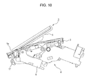
Fig. 10 illustrates how the movable body falls upon receiving an impulsive force. - An embodiment of the present invention is described with reference to the drawings. As illustrated in
Fig. 1 , an in-vehicle display apparatus according to the embodiment includes achassis 2 fixed to the rear surface of theinstallation member 1 in the vehicle interior, amovable body 3 that can protrude from and retract into an opening 1a formed in theinstallation member 1, and adriving mechanism 4 that moves themovable body 3 between a retraction position, in which themovable body 3 is in theopening 1a, and a protrusion position, in which themovable body 3 protrudes from theopening 1a. Theinstallation member 1 is a dashboard disposed below a front glass in front of a driver's seat. The horizontally extendingopening 1a is formed on the upper surface of theinstallation member 1. Thechassis 2 is fixed to the rear surface of theinstallation member 1 via a screw or by other means. Thechassis 2 has aconnection hole 2a that is continuous with the opening 1a of theinstallation member 1. - As illustrated in
Figs. 2 to 5 , themovable body 3 includes asupport board 5 and abase portion 6, which are integrally formed into a magnesium die casting or the like. Thesupport board 5 has a rectangular shape.Decorative boards 7 made of a synthetic resin are attached to the left and right of thesupport board 5. An edge portion of arectangular display panel 8 is fixed to an edge portion of thesupport board 5. An inner surface (front surface) of thesupport board 5 faces a rear surface of thedisplay panel 8 with a gap therebetween. Thedisplay panel 8 is a liquid crystal display (LCD). Three sides of thedisplay panel 8 excluding a bottom side are covered by an upper edge portion of thesupport board 5 and thedecorative boards 7. A large number ofreinforcement ribs 5a are formed in a honeycomb pattern on an upper side of the inner surface of thesupport board 5 to increase the mechanical strength of thesupport board 5. In addition, a readilybreakable portion 5b that extends substantially parallel to the lower side of thedisplay panel 8 is formed on the inner surface of thesupport board 5. The readilybreakable portion 5b divides the inner surface of thesupport board 5 into a wide upper area S1 and a narrow lower area S2. The readilybreakable portion 5b is a long groove that extends in the left-right direction of thesupport board 5 and has a recess-shaped cross section. The mechanical strength of the readilybreakable portion 5b is lower than that of other portions. - The
base portion 6 protrudes from a lower end portion of the rear surface of thesupport board 5 so as to be substantially orthogonal to thesupport board 5. A flat sheetreceivable portion 6a is formed on the inner surface of thebase portion 6 around a junction between thebase portion 6 and thesupport board 5. Multipleprotruding ribs 6b are formed in the sheetreceivable portion 6a to increase the strength around the sheetreceivable portion 6a. First bearingportions 6c andsecond bearing portions 6d are formed on the outer surface of thebase portion 6. The first andsecond bearing portions arms 14 and restrictingarms 16 of thedriving mechanism 4, which are described below, so as to be rotatable. - A
protection sheet 9 and astretchable sheet 10 are disposed on the inner surface of thesupport board 5 in a stacked manner. A main portion of the readilybreakable portion 5b excluding both end portions is covered by theprotection sheet 9 and thestretchable sheet 10. Theprotection sheet 9 is made of a material such as para-aramid fibers, which have excellent mechanical properties such as strength or a modulus of elasticity. The lower side of theprotection sheet 9 is fixed (bonded) to the lower area S2 of thesupport board 5 via means such as an adhesive or an adhesive tape, but theprotection sheet 9 is not bonded to the upper area S1 of thesupport board 5. Here, theprotection sheet 9 is only required to be fixed to one of two regions separated by the readilybreakable portion 5b. Thus, theprotection sheet 9 having a portion bonded to the sheetreceivable portion 6a of thebase portion 6 may extend to the upper area S1 across the readilybreakable portion 5b or theprotection sheet 9 having a portion bonded to the upper area S1 may extend to the lower area S2 or the sheetreceivable portion 6a across the readilybreakable portion 5b. - The
stretchable sheet 10 is a sheet member having excellent tensile strength or elasticity, such as a sheet obtained by three-dimensionally fusing an elastomer and a nonwoven fabric made of polyester fibers or polyurethane fibers or a composite sheet obtained by integrating an elastic sheet having a stretch property and a nonelastic fiber aggregate having a stretch property together in a stacked manner. In this embodiment, "ECSAINE"® of Toray Industries, Inc. is used as thestretchable sheet 10. Thestretchable sheet 10 covers theprotection sheet 9 and extends from the upper area S1 of thesupport board 5 to the sheetreceivable portion 6a of thebase portion 6. Upper and lower end portions of thestretchable sheet 10 are bonded to the upper area S1 and the sheetreceivable portion 6a, respectively. A middle portion of thestretchable sheet 10 excluding the upper and lower end portions, that is, a portion that overlaps theprotection sheet 9, which extends across the readilybreakable portion 5b is an unbonded portion that is not bonded to thesupport board 5. Thestretchable sheet 10 hasmultiple slits 10a, which extend from the bottom edge of thestretchable sheet 10 toward the top edge. The protrudingribs 6b that protrude from the sheetreceivable portion 6a are inserted into theslits 10, so that the protrudingribs 6b do not interfere with thestretchable sheet 10 when the lower end side of thestretchable sheet 10 is to be bonded to the sheetreceivable portion 6a of thebase portion 6. For this reason, if there is no protrusion, such as the protrudingribs 6b, in a portion to which thestretchable sheet 10 is bonded, thestretchable sheet 10 may not include theslits 10a. Thestretchable sheet 10 is only required to be fixed to two regions separated by the readilybreakable portion 5b. If the lower area S2 of thesupport board 5 has such a wide space as to allow thestretchable sheet 10 to be bonded thereto, the upper and lower end portions of thestretchable sheet 10 may be bonded to the upper area S1 and the lower area S2, respectively. - Helical extension springs 11 are stretched across uncovered portions of the readily
breakable portion 5b on the left and right sides of thestretchable sheet 10. End portions of eachhelical extension spring 11 are hooked on the upper area S1 of thesupport board 5 and the sheetreceivable portion 6a of thebase portion 6, respectively. Specifically, eachhelical extension spring 11 is stretched over continuous bent surfaces of thesupport board 5 and the sheetreceivable portion 6a so as to be substantially L-shaped. Here, it is only required that eachhelical extension spring 11 be hooked on two regions separated by the readilybreakable portion 5b. Thus, if the lower area S2 of thesupport board 5 is wide enough to allow one end portion of eachhelical extension spring 11 to be hooked thereon, the end portions of thehelical extension spring 11 may be hooked on the upper area S1 and the lower area S2 so that thehelical extension spring 11 forms a straight line. - As illustrated in
Figs. 6 and7 , thedriving mechanism 4 mainly includes amotor 12 attached to a rear portion on the back surface of thechassis 2, drivingarms 14 rotatably supported by ashaft 13 of thechassis 2, and restrictingarms 16 rotatably supported by ashaft 15 of thechassis 2. Rotation of themotor 12 is transmitted to the drivingarms 14 via a deceleration gear train or a clutch gear, which is not illustrated. One end portion of each drivingarm 14 is connected to a corresponding one of thefirst bearing portions 6c of thebase portion 6. The movable body 3 (thesupport board 5 and the base portion 6) moves between the retraction position and the protrusion position, which are described below, in accordance with a swing of the drivingarms 14. One end portion of each restrictingarm 16 is connected to a corresponding one of thesecond bearing portions 6d of thebase portion 6. Thus, the restrictingarms 16 restrict the orientation of themovable body 3 while themovable body 3 is moving. Although not illustrated, an openable cover that covers theconnection hole 2a is held by thechassis 2. This cover slides in accordance with a swing of the restrictingarms 16. Aprotection cap 17 made of a synthetic resin is attached to lower end portions of thesupport board 5 and thedisplay panel 8 to cover the lower end side of thedisplay panel 8. -
Fig. 6 illustrates the state where themovable body 3 is in the retraction position, in which themovable body 3 retracts into theopening 1a. Here, theopening 1a and theconnection hole 2a are covered by the above-described cover. When themotor 12 rotates in a first direction from this state, the drivingarms 14 swing in the clockwise direction ofFig. 6 . Thus, themovable body 3 starts moving along a rotation track of the restrictingarms 16 as illustrated inFig. 7 . At the same time, in accordance with the rotation of the restrictingarms 16, the cover slides in such a direction as to open theopening 1a and theconnection hole 2a and thus the upper side of thesupport board 5 and the upper side of thedisplay panel 8 protrude from theopening 1a to the vehicle interior. When themotor 12 continues rotating in the same direction, the drivingarm 14 pushes thebase portion 6 in such a direction as to cause thesupport board 5 to protrude. Thus, as illustrated inFig. 1 , a large part of thesupport board 5 and a large part of thedisplay panel 8 protrude from theopening 1a. When themotor 12 stops rotating at this time, themovable body 3 is held in the protrusion position in which thedisplay panel 8 faces the vehicle interior, so that an occupant in the vehicle interior can see an image displayed on a display screen of thedisplay panel 8. In addition, when themotor 12 rotates in a second direction while themovable body 3 is in the protrusion position illustrated inFig. 1 , the drivingarms 14 swing in the counterclockwise direction ofFig. 6 and draw thebase portion 6 back in such a direction as to retract thebase portion 6. Thus, themovable body 3 retracts into theopening 1a and returns to the retraction position illustrated inFig. 6 . - While the in-vehicle display apparatus having the above structure is in a use state in which the
support board 5 of themovable body 3 and thedisplay panel 8 protrude from theopening 1a, if, for example, an occupant in a moving vehicle hits his/her head or another body part against thedisplay panel 8 due to a sudden braking, a large impulsive force directed toward the front of the vehicle interior is exerted on thesupport board 5 that holds thedisplay panel 8, as indicated by arrow A ofFig. 1 . Consequently, as illustrated inFig. 8 , thesupport board 5 falls to the front of the vehicle interior due to the impact and breaks off along the readilybreakable portion 5b, so that the upper area S1 of thesupport board 5 holding thedisplay panel 8 and the lower area S2 of thesupport board 5 that is continuous with thebase portion 6 become disconnected from each other at the broken-off point P. - The
stretchable sheet 10 is interposed between thesupport board 5 and thedisplay panel 8 so as to extend across the readilybreakable portion 5b. The upper and lower end portions of thestretchable sheet 10 are bonded to the upper area S1 of thesupport board 5 and the sheetreceivable portion 6a of thebase portion 6, respectively. Thus, thestretchable sheet 10 is stretched while being fixed to the upper area S1 of the broken-offsupport board 5 and the upper area S1 of the broken-offsupport board 5 and thedisplay panel 8 slide forward (obliquely upward to the right inFig. 8 ) a distance equivalent to the amount by which thestretchable sheet 10 is stretched. Since the broken-off portion of thesupport board 5 remains connected to thestretchable sheet 10, the broken-off portion of thesupport board 5 and thedisplay panel 8 can be prevented from flying into the vehicle interior. Moreover, since the broken-off portion of thesupport board 5 and thedisplay panel 8 fall while sliding forward (obliquely upward), the lower end portions of thesupport board 5 and thedisplay panel 8 become detached from theprotection cap 17 as illustrated inFig. 9 and then protrude from theopening 1a of theinstallation member 1 as illustrated inFig. 10 . Accordingly, the lower end portions of thesupport board 5 and thedisplay panel 8 are prevented from entering a portion under theinstallation member 1 near theopening 1a (to the left inFig. 9 ) and thus from raising a portion of theinstallation member 1 around theopening 1a as a result of the fall of the broken-off portion of thesupport board 5 and thedisplay panel 8. Thus, the portion of theinstallation member 1 around theopening 1a can be prevented from being deformed or damaged. - Moreover, the
protection sheet 9 is interposed between thesupport board 5 and thestretchable sheet 10 so as to extend across the readilybreakable portion 5b and the lower side of theprotection sheet 9 is bonded to the lower area S2 of thesupport board 5. Thus, when thesupport board 5 breaks off along the readilybreakable portion 5b, theprotection sheet 9 covers the broken-off surface to prevent thestretchable sheet 10 from coming into contact with the broken-off surface. Consequently, thestretchable sheet 10 does not come into direct contact with the sharp broken-off surface at the broken-off point P, thereby preventing the broken-off surface of thesupport board 5 from tearing thestretchable sheet 10. - In addition, a pair of helical extension springs 11 are interposed between the
support board 5 and thedisplay panel 8 so as to cross the readilybreakable portion 5b and the end portions of eachhelical extension spring 11 are hooked on the upper area S1 of thesupport board 5 and the sheetreceivable portion 6a of thebase portion 6, respectively. Thus, when the upper area S1 of thesupport board 5 disconnected from the lower area S2 due to an impact moves forward together with thedisplay panel 8, not only thestretchable sheet 10, but also the helical extension springs 11 are stretched while being hooked on the upper area S1 of thesupport board 5. Thesupport board 5, which has broken off due to an impact, and thedisplay panel 8 fall while sliding forward as illustrated inFig. 10 , and then instantaneously return to an erect position illustrated inFig. 1 due to the elasticity of the helical extension springs 11. Thus, the lower end portions of thesupport board 5 and thedisplay panel 8, which are protrusions, return to the inside of theopening 1a to be held in theprotection cap 17 and do not face the occupant. In addition, the broken-off portion of thesupport board 5 remains connected to thestretchable sheet 10 and the helical extension springs 11 at three points, thereby more reliably preventing the broken-off portion of thesupport board 5 and thedisplay panel 8 from flying away. - As described above, in the in-vehicle display apparatus according to the embodiment, a readily
breakable portion 5b is formed on thesupport board 5 of themovable body 3 that holds thedisplay panel 8. Thesupport board 5 breaks off along the readilybreakable portion 5b when thesupport board 5 falls forward due to an impact that thesupport board 5 has received when an occupant hits his/her head or another body part against thedisplay panel 8 that protrudes from theopening 1a of theinstallation member 1 and that is held in an erect position. Thestretchable sheet 10 disposed on the back surface of thedisplay panel 8 is bonded to two regions separated by the readilybreakable portion 5b (the upper area S1 of thesupport board 5 and the sheetreceivable portion 6a of the base portion 6) and is stretched while being fixed to the broken-off upper area S1 of thesupport board 5. Thus, the broken-off portion of thesupport board 5 remains connected to thestretchable sheet 10 and the broken-off portion of thesupport board 5 and thedisplay panel 8 can be prevented from breaking off at the broken-off point and from flying into the vehicle interior. Moreover, since the broken-off portion of thesupport board 5 and thedisplay panel 8 fall while sliding forward (obliquely upward) a distance equivalent to the amount by which thestretchable sheet 10 is stretched, the lower end portions of thesupport board 5 and thedisplay panel 8 do not hit the lower surface of theinstallation member 1 near theopening 1a. Thus, a portion of theinstallation member 1 around theopening 1a can be prevented from being deformed or damaged, thereby improving the safety of an occupant. - In addition, in the embodiment, the
movable body 3 has abase portion 6 that protrudes from a lower end portion of the rear surface of thesupport board 5, and the upper area S1 of thesupport board 5 and the sheetreceivable portion 6a of thebase portion 6, to both of which thestretchable sheet 10 is bonded, are substantially orthogonal to each other. Thus, thestretchable sheet 10 can be reliably stretched while being prevented from being detached from the upper area S1 and the sheetreceivable portion 6a. Moreover, the middle portion of thestretchable sheet 10 excluding the upper and lower end portions, or a portion of thestretchable sheet 10 that overlaps theprotection sheet 9 attached to thesupport board 5 so as to extend across the readilybreakable portion 5b, is an unbonded portion that is not bonded to thesupport board 5. By having the unbonded portion, thestretchable sheet 10 can be reliably stretched. - The
stretchable sheet 10 has theslits 10a extending in a direction that crosses the readilybreakable portion 5b. Protrusions (protrudingrib 6b) formed on the sheetreceivable portion 6a are inserted into theslits 10a. Thus, thestretchable sheet 10 can be readily and reliably bonded to the sheetreceivable portion 6a. Moreover, in case where thestretchable sheet 10 is partially torn when thesupport board 5 breaks off, theslits 10a stop the tear from being extended throughout the entirestretchable sheet 10. - In the embodiment, the
protection sheet 9 is interposed between thesupport board 5 and thestretchable sheet 10 so as to extend across the readilybreakable portion 5b and the lower side of theprotection sheet 9 is bonded to the lower area S2 of thesupport board 5. Thus, when thesupport board 5 breaks off along the readilybreakable portion 5b, theprotection sheet 9 covers the broken-off surface to prevent the broken-off surface from coming into contact with thestretchable sheet 10. Consequently, thestretchable sheet 10 can be prevented from coming into direct contact with the sharp broken-off surface at the broken-off point P and theprotection sheet 9 prevents thestretchable sheet 10 from being torn. Thus, thestretchable sheet 10 can be reliably stretched. - In the embodiment, the inner surface of the
support board 5 has a long groove having a recess-shaped cross section, which is used as the readilybreakable portion 5b. Since the readilybreakable portion 5b is not exposed to the outside, the readilybreakable portion 5b is advantageous with regard to appearance. Moreover, the readilybreakable portion 5b is advantageous with regard to the production process because the long groove (readilybreakable portion 5b) can be included in the shape of the die used when thesupport board 5 and thebase portion 6 are integrally formed into a magnesium die casting or the like. - In the embodiment, the
movable body 3 is moved by thedriving mechanism 4 including themotor 12, serving as a driving source, and the drivingarms 14 rotated by themotor 12. However, thedriving mechanism 4 may be configured differently as long as it can move themovable body 3 between the retraction position and the protrusion position.
Claims (6)
- An in-vehicle display apparatus including a movable body (3) that is retractable into and withdrawable from an opening (1a) formed in an installation member (1) in a vehicle interior; a display panel (8) having a rectangular shape and attached to a support board (5) of the movable body (3); and a driving mechanism (4) that moves the movable body (3) between a retraction position, in which the movable body (3) is in the opening (1a), and a protrusion position, in which the movable body (3) protrudes from the opening (1a), the display panel (8) protruding from the opening (1a) in an erect position, in which the display panel (8) faces the vehicle interior, while the movable body (3) is in the protrusion position, the in-vehicle display apparatus
characterized in that
the support board (5) has a readily breakable portion (5b) that extends substantially parallel to a lower edge of the display panel (8),
a stretchable sheet (10) is interposed between the support board (5) and the display panel (8) so as to extend across the readily breakable portion (5b), and
the stretchable sheet (10) is fixed to the movable body (3) at at least two regions that are separated by the readily breakable portion (5b). - The in-vehicle display apparatus according to Claim 1, characterized in that
the movable body (3) includes a base portion (6) that protrudes from a lower end portion of a rear surface of the support board (5), and
the stretchable sheet (10) is bonded to a portion of the support board (5) above the readily breakable portion (5b) and to the base portion (6). - The in-vehicle display apparatus according to Claim 1 or 2, characterized in that a middle portion of the stretchable sheet (10) that overlaps the readily breakable portion (5b) is an unbonded portion that is not bonded to the support board (5).
- The in-vehicle display apparatus according to any one of Claims 1 to 3, characterized in that
a protection sheet (9) is interposed between the support board (5) and the stretchable sheet (10) so as to extend across the readily breakable portion (5b), and
only one side of the protection sheet (9) is fixed to the movable body (3), the side being defined with respect to the readily breakable portion (5b). - The in-vehicle display apparatus according to any one of Claims 1 to 4, characterized in that the stretchable sheet (10) has a slit (10a) extending so as to cross the readily breakable portion (5b).
- The in-vehicle display apparatus according to any one of Claims 1 to 5, characterized in that the readily breakable portion (5b) is a long groove formed on an inner surface of the support board (5) and having a recess-shaped cross section.
Applications Claiming Priority (1)
| Application Number | Priority Date | Filing Date | Title |
|---|---|---|---|
| JP2012133867A JP5851943B2 (en) | 2012-06-13 | 2012-06-13 | In-vehicle display device |
Publications (2)
| Publication Number | Publication Date |
|---|---|
| EP2674330A1 true EP2674330A1 (en) | 2013-12-18 |
| EP2674330B1 EP2674330B1 (en) | 2015-03-11 |
Family
ID=48625797
Family Applications (1)
| Application Number | Title | Priority Date | Filing Date |
|---|---|---|---|
| EP20130171051 Active EP2674330B1 (en) | 2012-06-13 | 2013-06-07 | In-vehicle display apparatus |
Country Status (2)
| Country | Link |
|---|---|
| EP (1) | EP2674330B1 (en) |
| JP (1) | JP5851943B2 (en) |
Cited By (1)
| Publication number | Priority date | Publication date | Assignee | Title |
|---|---|---|---|---|
| EP2854845A4 (en) * | 2012-06-01 | 2015-11-18 | Ibc Pharmaceuticals Inc | MULTIMERIC COMPLEXES WITH BETTER IN VIVO STABILITY, BETTER PHARMACOKINETICS AND BETTER EFFICIENCY |
Families Citing this family (2)
| Publication number | Priority date | Publication date | Assignee | Title |
|---|---|---|---|---|
| JP6355566B2 (en) * | 2015-01-08 | 2018-07-11 | アルパイン株式会社 | In-vehicle display device |
| JP6355567B2 (en) * | 2015-01-13 | 2018-07-11 | アルパイン株式会社 | In-vehicle display device |
Citations (3)
| Publication number | Priority date | Publication date | Assignee | Title |
|---|---|---|---|---|
| JP2008074303A (en) | 2006-09-22 | 2008-04-03 | Alpine Electronics Inc | Display device |
| GB2450544A (en) * | 2007-06-29 | 2008-12-31 | Centurion Electronics Plc | Roof mounted displays |
| WO2010041310A1 (en) * | 2008-10-07 | 2010-04-15 | パイオニア株式会社 | Display device |
Family Cites Families (5)
| Publication number | Priority date | Publication date | Assignee | Title |
|---|---|---|---|---|
| DE4109497C1 (en) * | 1991-03-22 | 1992-08-13 | Mercedes-Benz Aktiengesellschaft, 7000 Stuttgart, De | |
| JP2000330475A (en) * | 1999-05-24 | 2000-11-30 | Mitsubishi Electric Corp | Mounting structure of display device for vehicle |
| ATE502815T1 (en) * | 2005-12-22 | 2011-04-15 | Johnson Controls Tech Co | BACKREST ENTERTAINMENT DISPLAY SYSTEM |
| JP2007290552A (en) * | 2006-04-25 | 2007-11-08 | Toyota Motor Corp | Support structure of supported body |
| JP2009050522A (en) * | 2007-08-28 | 2009-03-12 | Toyota Boshoku Corp | Vehicle seats |
-
2012
- 2012-06-13 JP JP2012133867A patent/JP5851943B2/en active Active
-
2013
- 2013-06-07 EP EP20130171051 patent/EP2674330B1/en active Active
Patent Citations (3)
| Publication number | Priority date | Publication date | Assignee | Title |
|---|---|---|---|---|
| JP2008074303A (en) | 2006-09-22 | 2008-04-03 | Alpine Electronics Inc | Display device |
| GB2450544A (en) * | 2007-06-29 | 2008-12-31 | Centurion Electronics Plc | Roof mounted displays |
| WO2010041310A1 (en) * | 2008-10-07 | 2010-04-15 | パイオニア株式会社 | Display device |
Cited By (1)
| Publication number | Priority date | Publication date | Assignee | Title |
|---|---|---|---|---|
| EP2854845A4 (en) * | 2012-06-01 | 2015-11-18 | Ibc Pharmaceuticals Inc | MULTIMERIC COMPLEXES WITH BETTER IN VIVO STABILITY, BETTER PHARMACOKINETICS AND BETTER EFFICIENCY |
Also Published As
| Publication number | Publication date |
|---|---|
| EP2674330B1 (en) | 2015-03-11 |
| JP5851943B2 (en) | 2016-02-03 |
| JP2013256217A (en) | 2013-12-26 |
Similar Documents
| Publication | Publication Date | Title |
|---|---|---|
| EP2676847B1 (en) | In-vehicle display apparatus | |
| JP5997655B2 (en) | Vehicle display device | |
| CN101570140B (en) | Instrument panel and shield member | |
| CN102476621B (en) | Passenger air-bag door | |
| CN202557258U (en) | Sun shield | |
| US9457735B2 (en) | Vehicular interior component | |
| EP2674330B1 (en) | In-vehicle display apparatus | |
| KR102648605B1 (en) | Air bag device for driver | |
| JP2009113584A (en) | Shift device | |
| CN109278557A (en) | Instrument board for vehicle | |
| CN202294523U (en) | Automobile rearview mirror | |
| JP6035184B2 (en) | vehicle | |
| JP2015058720A (en) | Display device for vehicle | |
| JP2023172368A (en) | Vehicle interior parts | |
| JP7375621B2 (en) | Automotive display device | |
| JP5012014B2 (en) | Installation structure of vehicle communication device | |
| US9221416B2 (en) | Trim assembly for covering airbag | |
| JP6975892B2 (en) | Panel structure | |
| JP7131404B2 (en) | vehicle display | |
| JP2010269750A (en) | Shading hood for car navigation | |
| JP5772604B2 (en) | Display unit mounting structure | |
| JP2019217937A (en) | Air bag lid member | |
| JP5888553B2 (en) | Display unit mounting structure | |
| JP2013216319A (en) | Shield plate and vehicle structure including the same | |
| JP3114361U (en) | Visual device attached to the sun visor of an automobile |
Legal Events
| Date | Code | Title | Description |
|---|---|---|---|
| PUAI | Public reference made under article 153(3) epc to a published international application that has entered the european phase |
Free format text: ORIGINAL CODE: 0009012 |
|
| AK | Designated contracting states |
Kind code of ref document: A1 Designated state(s): AL AT BE BG CH CY CZ DE DK EE ES FI FR GB GR HR HU IE IS IT LI LT LU LV MC MK MT NL NO PL PT RO RS SE SI SK SM TR |
|
| AX | Request for extension of the european patent |
Extension state: BA ME |
|
| 17P | Request for examination filed |
Effective date: 20140410 |
|
| RBV | Designated contracting states (corrected) |
Designated state(s): AL AT BE BG CH CY CZ DE DK EE ES FI FR GB GR HR HU IE IS IT LI LT LU LV MC MK MT NL NO PL PT RO RS SE SI SK SM TR |
|
| GRAP | Despatch of communication of intention to grant a patent |
Free format text: ORIGINAL CODE: EPIDOSNIGR1 |
|
| INTG | Intention to grant announced |
Effective date: 20141028 |
|
| GRAS | Grant fee paid |
Free format text: ORIGINAL CODE: EPIDOSNIGR3 |
|
| GRAA | (expected) grant |
Free format text: ORIGINAL CODE: 0009210 |
|
| AK | Designated contracting states |
Kind code of ref document: B1 Designated state(s): AL AT BE BG CH CY CZ DE DK EE ES FI FR GB GR HR HU IE IS IT LI LT LU LV MC MK MT NL NO PL PT RO RS SE SI SK SM TR |
|
| REG | Reference to a national code |
Ref country code: GB Ref legal event code: FG4D |
|
| REG | Reference to a national code |
Ref country code: CH Ref legal event code: EP |
|
| REG | Reference to a national code |
Ref country code: IE Ref legal event code: FG4D |
|
| REG | Reference to a national code |
Ref country code: AT Ref legal event code: REF Ref document number: 715123 Country of ref document: AT Kind code of ref document: T Effective date: 20150415 |
|
| REG | Reference to a national code |
Ref country code: DE Ref legal event code: R096 Ref document number: 602013001159 Country of ref document: DE Effective date: 20150423 |
|
| REG | Reference to a national code |
Ref country code: NL Ref legal event code: VDEP Effective date: 20150311 |
|
| REG | Reference to a national code |
Ref country code: NL Ref legal event code: VDEP Effective date: 20150311 |
|
| PG25 | Lapsed in a contracting state [announced via postgrant information from national office to epo] |
Ref country code: LT Free format text: LAPSE BECAUSE OF FAILURE TO SUBMIT A TRANSLATION OF THE DESCRIPTION OR TO PAY THE FEE WITHIN THE PRESCRIBED TIME-LIMIT Effective date: 20150311 Ref country code: SE Free format text: LAPSE BECAUSE OF FAILURE TO SUBMIT A TRANSLATION OF THE DESCRIPTION OR TO PAY THE FEE WITHIN THE PRESCRIBED TIME-LIMIT Effective date: 20150311 Ref country code: NO Free format text: LAPSE BECAUSE OF FAILURE TO SUBMIT A TRANSLATION OF THE DESCRIPTION OR TO PAY THE FEE WITHIN THE PRESCRIBED TIME-LIMIT Effective date: 20150611 Ref country code: FI Free format text: LAPSE BECAUSE OF FAILURE TO SUBMIT A TRANSLATION OF THE DESCRIPTION OR TO PAY THE FEE WITHIN THE PRESCRIBED TIME-LIMIT Effective date: 20150311 Ref country code: HR Free format text: LAPSE BECAUSE OF FAILURE TO SUBMIT A TRANSLATION OF THE DESCRIPTION OR TO PAY THE FEE WITHIN THE PRESCRIBED TIME-LIMIT Effective date: 20150311 Ref country code: ES Free format text: LAPSE BECAUSE OF FAILURE TO SUBMIT A TRANSLATION OF THE DESCRIPTION OR TO PAY THE FEE WITHIN THE PRESCRIBED TIME-LIMIT Effective date: 20150311 |
|
| REG | Reference to a national code |
Ref country code: AT Ref legal event code: MK05 Ref document number: 715123 Country of ref document: AT Kind code of ref document: T Effective date: 20150311 |
|
| REG | Reference to a national code |
Ref country code: LT Ref legal event code: MG4D |
|
| PG25 | Lapsed in a contracting state [announced via postgrant information from national office to epo] |
Ref country code: LV Free format text: LAPSE BECAUSE OF FAILURE TO SUBMIT A TRANSLATION OF THE DESCRIPTION OR TO PAY THE FEE WITHIN THE PRESCRIBED TIME-LIMIT Effective date: 20150311 Ref country code: GR Free format text: LAPSE BECAUSE OF FAILURE TO SUBMIT A TRANSLATION OF THE DESCRIPTION OR TO PAY THE FEE WITHIN THE PRESCRIBED TIME-LIMIT Effective date: 20150612 Ref country code: RS Free format text: LAPSE BECAUSE OF FAILURE TO SUBMIT A TRANSLATION OF THE DESCRIPTION OR TO PAY THE FEE WITHIN THE PRESCRIBED TIME-LIMIT Effective date: 20150311 |
|
| PG25 | Lapsed in a contracting state [announced via postgrant information from national office to epo] |
Ref country code: NL Free format text: LAPSE BECAUSE OF FAILURE TO SUBMIT A TRANSLATION OF THE DESCRIPTION OR TO PAY THE FEE WITHIN THE PRESCRIBED TIME-LIMIT Effective date: 20150311 |
|
| PG25 | Lapsed in a contracting state [announced via postgrant information from national office to epo] |
Ref country code: PT Free format text: LAPSE BECAUSE OF FAILURE TO SUBMIT A TRANSLATION OF THE DESCRIPTION OR TO PAY THE FEE WITHIN THE PRESCRIBED TIME-LIMIT Effective date: 20150713 Ref country code: SK Free format text: LAPSE BECAUSE OF FAILURE TO SUBMIT A TRANSLATION OF THE DESCRIPTION OR TO PAY THE FEE WITHIN THE PRESCRIBED TIME-LIMIT Effective date: 20150311 Ref country code: EE Free format text: LAPSE BECAUSE OF FAILURE TO SUBMIT A TRANSLATION OF THE DESCRIPTION OR TO PAY THE FEE WITHIN THE PRESCRIBED TIME-LIMIT Effective date: 20150311 Ref country code: CZ Free format text: LAPSE BECAUSE OF FAILURE TO SUBMIT A TRANSLATION OF THE DESCRIPTION OR TO PAY THE FEE WITHIN THE PRESCRIBED TIME-LIMIT Effective date: 20150311 Ref country code: RO Free format text: LAPSE BECAUSE OF FAILURE TO SUBMIT A TRANSLATION OF THE DESCRIPTION OR TO PAY THE FEE WITHIN THE PRESCRIBED TIME-LIMIT Effective date: 20150311 |
|
| PG25 | Lapsed in a contracting state [announced via postgrant information from national office to epo] |
Ref country code: PL Free format text: LAPSE BECAUSE OF FAILURE TO SUBMIT A TRANSLATION OF THE DESCRIPTION OR TO PAY THE FEE WITHIN THE PRESCRIBED TIME-LIMIT Effective date: 20150311 Ref country code: AT Free format text: LAPSE BECAUSE OF FAILURE TO SUBMIT A TRANSLATION OF THE DESCRIPTION OR TO PAY THE FEE WITHIN THE PRESCRIBED TIME-LIMIT Effective date: 20150311 Ref country code: IS Free format text: LAPSE BECAUSE OF FAILURE TO SUBMIT A TRANSLATION OF THE DESCRIPTION OR TO PAY THE FEE WITHIN THE PRESCRIBED TIME-LIMIT Effective date: 20150711 |
|
| REG | Reference to a national code |
Ref country code: DE Ref legal event code: R097 Ref document number: 602013001159 Country of ref document: DE |
|
| PG25 | Lapsed in a contracting state [announced via postgrant information from national office to epo] |
Ref country code: IT Free format text: LAPSE BECAUSE OF FAILURE TO SUBMIT A TRANSLATION OF THE DESCRIPTION OR TO PAY THE FEE WITHIN THE PRESCRIBED TIME-LIMIT Effective date: 20150311 |
|
| PLBE | No opposition filed within time limit |
Free format text: ORIGINAL CODE: 0009261 |
|
| STAA | Information on the status of an ep patent application or granted ep patent |
Free format text: STATUS: NO OPPOSITION FILED WITHIN TIME LIMIT |
|
| PG25 | Lapsed in a contracting state [announced via postgrant information from national office to epo] |
Ref country code: MC Free format text: LAPSE BECAUSE OF FAILURE TO SUBMIT A TRANSLATION OF THE DESCRIPTION OR TO PAY THE FEE WITHIN THE PRESCRIBED TIME-LIMIT Effective date: 20150311 Ref country code: DK Free format text: LAPSE BECAUSE OF FAILURE TO SUBMIT A TRANSLATION OF THE DESCRIPTION OR TO PAY THE FEE WITHIN THE PRESCRIBED TIME-LIMIT Effective date: 20150311 |
|
| 26N | No opposition filed |
Effective date: 20151214 |
|
| PG25 | Lapsed in a contracting state [announced via postgrant information from national office to epo] |
Ref country code: LU Free format text: LAPSE BECAUSE OF FAILURE TO SUBMIT A TRANSLATION OF THE DESCRIPTION OR TO PAY THE FEE WITHIN THE PRESCRIBED TIME-LIMIT Effective date: 20150607 Ref country code: SI Free format text: LAPSE BECAUSE OF FAILURE TO SUBMIT A TRANSLATION OF THE DESCRIPTION OR TO PAY THE FEE WITHIN THE PRESCRIBED TIME-LIMIT Effective date: 20150311 |
|
| REG | Reference to a national code |
Ref country code: IE Ref legal event code: MM4A |
|
| PG25 | Lapsed in a contracting state [announced via postgrant information from national office to epo] |
Ref country code: IE Free format text: LAPSE BECAUSE OF NON-PAYMENT OF DUE FEES Effective date: 20150607 |
|
| REG | Reference to a national code |
Ref country code: FR Ref legal event code: PLFP Year of fee payment: 4 |
|
| PG25 | Lapsed in a contracting state [announced via postgrant information from national office to epo] |
Ref country code: BE Free format text: LAPSE BECAUSE OF FAILURE TO SUBMIT A TRANSLATION OF THE DESCRIPTION OR TO PAY THE FEE WITHIN THE PRESCRIBED TIME-LIMIT Effective date: 20150311 |
|
| PG25 | Lapsed in a contracting state [announced via postgrant information from national office to epo] |
Ref country code: MT Free format text: LAPSE BECAUSE OF FAILURE TO SUBMIT A TRANSLATION OF THE DESCRIPTION OR TO PAY THE FEE WITHIN THE PRESCRIBED TIME-LIMIT Effective date: 20150311 |
|
| REG | Reference to a national code |
Ref country code: CH Ref legal event code: PL |
|
| PG25 | Lapsed in a contracting state [announced via postgrant information from national office to epo] |
Ref country code: LI Free format text: LAPSE BECAUSE OF NON-PAYMENT OF DUE FEES Effective date: 20160630 Ref country code: CH Free format text: LAPSE BECAUSE OF NON-PAYMENT OF DUE FEES Effective date: 20160630 |
|
| PG25 | Lapsed in a contracting state [announced via postgrant information from national office to epo] |
Ref country code: BG Free format text: LAPSE BECAUSE OF FAILURE TO SUBMIT A TRANSLATION OF THE DESCRIPTION OR TO PAY THE FEE WITHIN THE PRESCRIBED TIME-LIMIT Effective date: 20150311 Ref country code: HU Free format text: LAPSE BECAUSE OF FAILURE TO SUBMIT A TRANSLATION OF THE DESCRIPTION OR TO PAY THE FEE WITHIN THE PRESCRIBED TIME-LIMIT; INVALID AB INITIO Effective date: 20130607 |
|
| REG | Reference to a national code |
Ref country code: FR Ref legal event code: PLFP Year of fee payment: 5 |
|
| PG25 | Lapsed in a contracting state [announced via postgrant information from national office to epo] |
Ref country code: CY Free format text: LAPSE BECAUSE OF FAILURE TO SUBMIT A TRANSLATION OF THE DESCRIPTION OR TO PAY THE FEE WITHIN THE PRESCRIBED TIME-LIMIT Effective date: 20150311 |
|
| REG | Reference to a national code |
Ref country code: DE Ref legal event code: R082 Ref document number: 602013001159 Country of ref document: DE Representative=s name: SCHMITT-NILSON SCHRAUD WAIBEL WOHLFROM PATENTA, DE |
|
| PG25 | Lapsed in a contracting state [announced via postgrant information from national office to epo] |
Ref country code: TR Free format text: LAPSE BECAUSE OF FAILURE TO SUBMIT A TRANSLATION OF THE DESCRIPTION OR TO PAY THE FEE WITHIN THE PRESCRIBED TIME-LIMIT Effective date: 20150311 |
|
| PG25 | Lapsed in a contracting state [announced via postgrant information from national office to epo] |
Ref country code: SM Free format text: LAPSE BECAUSE OF FAILURE TO SUBMIT A TRANSLATION OF THE DESCRIPTION OR TO PAY THE FEE WITHIN THE PRESCRIBED TIME-LIMIT Effective date: 20150311 |
|
| REG | Reference to a national code |
Ref country code: FR Ref legal event code: PLFP Year of fee payment: 6 |
|
| PG25 | Lapsed in a contracting state [announced via postgrant information from national office to epo] |
Ref country code: MK Free format text: LAPSE BECAUSE OF FAILURE TO SUBMIT A TRANSLATION OF THE DESCRIPTION OR TO PAY THE FEE WITHIN THE PRESCRIBED TIME-LIMIT Effective date: 20150311 |
|
| PG25 | Lapsed in a contracting state [announced via postgrant information from national office to epo] |
Ref country code: AL Free format text: LAPSE BECAUSE OF FAILURE TO SUBMIT A TRANSLATION OF THE DESCRIPTION OR TO PAY THE FEE WITHIN THE PRESCRIBED TIME-LIMIT Effective date: 20150311 |
|
| PGFP | Annual fee paid to national office [announced via postgrant information from national office to epo] |
Ref country code: DE Payment date: 20250618 Year of fee payment: 13 |
|
| PGFP | Annual fee paid to national office [announced via postgrant information from national office to epo] |
Ref country code: GB Payment date: 20250618 Year of fee payment: 13 |
|
| PGFP | Annual fee paid to national office [announced via postgrant information from national office to epo] |
Ref country code: FR Payment date: 20250624 Year of fee payment: 13 |