EP2674117A1 - Übertragungseinrichtung zum Übertragen einer Kraft und eines Drehmoments in einem medizinischen Instrument - Google Patents
Übertragungseinrichtung zum Übertragen einer Kraft und eines Drehmoments in einem medizinischen Instrument Download PDFInfo
- Publication number
- EP2674117A1 EP2674117A1 EP13167574.6A EP13167574A EP2674117A1 EP 2674117 A1 EP2674117 A1 EP 2674117A1 EP 13167574 A EP13167574 A EP 13167574A EP 2674117 A1 EP2674117 A1 EP 2674117A1
- Authority
- EP
- European Patent Office
- Prior art keywords
- transmission member
- transmission
- coupling portion
- sleeve
- transfer
- Prior art date
- Legal status (The legal status is an assumption and is not a legal conclusion. Google has not performed a legal analysis and makes no representation as to the accuracy of the status listed.)
- Granted
Links
Images


Classifications
-
- F—MECHANICAL ENGINEERING; LIGHTING; HEATING; WEAPONS; BLASTING
- F16—ENGINEERING ELEMENTS AND UNITS; GENERAL MEASURES FOR PRODUCING AND MAINTAINING EFFECTIVE FUNCTIONING OF MACHINES OR INSTALLATIONS; THERMAL INSULATION IN GENERAL
- F16C—SHAFTS; FLEXIBLE SHAFTS; ELEMENTS OR CRANKSHAFT MECHANISMS; ROTARY BODIES OTHER THAN GEARING ELEMENTS; BEARINGS
- F16C1/00—Flexible shafts; Mechanical means for transmitting movement in a flexible sheathing
- F16C1/02—Flexible shafts; Mechanical means for transmitting movement in a flexible sheathing for conveying rotary movements
- F16C1/04—Articulated shafts
-
- A—HUMAN NECESSITIES
- A61—MEDICAL OR VETERINARY SCIENCE; HYGIENE
- A61B—DIAGNOSIS; SURGERY; IDENTIFICATION
- A61B17/00—Surgical instruments, devices or methods
- A61B17/28—Surgical forceps
- A61B17/29—Forceps for use in minimally invasive surgery
-
- A—HUMAN NECESSITIES
- A61—MEDICAL OR VETERINARY SCIENCE; HYGIENE
- A61B—DIAGNOSIS; SURGERY; IDENTIFICATION
- A61B17/00—Surgical instruments, devices or methods
- A61B17/32—Surgical cutting instruments
- A61B17/320016—Endoscopic cutting instruments, e.g. arthroscopes, resectoscopes
- A61B17/32002—Endoscopic cutting instruments, e.g. arthroscopes, resectoscopes with continuously rotating, oscillating or reciprocating cutting instruments
-
- A—HUMAN NECESSITIES
- A61—MEDICAL OR VETERINARY SCIENCE; HYGIENE
- A61B—DIAGNOSIS; SURGERY; IDENTIFICATION
- A61B17/00—Surgical instruments, devices or methods
- A61B2017/00526—Methods of manufacturing
-
- A—HUMAN NECESSITIES
- A61—MEDICAL OR VETERINARY SCIENCE; HYGIENE
- A61B—DIAGNOSIS; SURGERY; IDENTIFICATION
- A61B17/00—Surgical instruments, devices or methods
- A61B2017/00681—Aspects not otherwise provided for
- A61B2017/0069—Aspects not otherwise provided for with universal joint, cardan joint
-
- A—HUMAN NECESSITIES
- A61—MEDICAL OR VETERINARY SCIENCE; HYGIENE
- A61B—DIAGNOSIS; SURGERY; IDENTIFICATION
- A61B17/00—Surgical instruments, devices or methods
- A61B17/28—Surgical forceps
- A61B17/29—Forceps for use in minimally invasive surgery
- A61B2017/2901—Details of shaft
- A61B2017/2902—Details of shaft characterized by features of the actuating rod
-
- A—HUMAN NECESSITIES
- A61—MEDICAL OR VETERINARY SCIENCE; HYGIENE
- A61B—DIAGNOSIS; SURGERY; IDENTIFICATION
- A61B17/00—Surgical instruments, devices or methods
- A61B17/28—Surgical forceps
- A61B17/29—Forceps for use in minimally invasive surgery
- A61B2017/2901—Details of shaft
- A61B2017/2902—Details of shaft characterized by features of the actuating rod
- A61B2017/2903—Details of shaft characterized by features of the actuating rod transferring rotary motion
-
- A—HUMAN NECESSITIES
- A61—MEDICAL OR VETERINARY SCIENCE; HYGIENE
- A61B—DIAGNOSIS; SURGERY; IDENTIFICATION
- A61B17/00—Surgical instruments, devices or methods
- A61B17/28—Surgical forceps
- A61B17/29—Forceps for use in minimally invasive surgery
- A61B2017/2901—Details of shaft
- A61B2017/2905—Details of shaft flexible
-
- A—HUMAN NECESSITIES
- A61—MEDICAL OR VETERINARY SCIENCE; HYGIENE
- A61B—DIAGNOSIS; SURGERY; IDENTIFICATION
- A61B17/00—Surgical instruments, devices or methods
- A61B17/28—Surgical forceps
- A61B17/29—Forceps for use in minimally invasive surgery
- A61B2017/2926—Details of heads or jaws
- A61B2017/2927—Details of heads or jaws the angular position of the head being adjustable with respect to the shaft
- A61B2017/2929—Details of heads or jaws the angular position of the head being adjustable with respect to the shaft with a head rotatable about the longitudinal axis of the shaft
-
- A—HUMAN NECESSITIES
- A61—MEDICAL OR VETERINARY SCIENCE; HYGIENE
- A61B—DIAGNOSIS; SURGERY; IDENTIFICATION
- A61B17/00—Surgical instruments, devices or methods
- A61B17/32—Surgical cutting instruments
- A61B17/320016—Endoscopic cutting instruments, e.g. arthroscopes, resectoscopes
- A61B17/32002—Endoscopic cutting instruments, e.g. arthroscopes, resectoscopes with continuously rotating, oscillating or reciprocating cutting instruments
- A61B2017/320032—Details of the rotating or oscillating shaft, e.g. using a flexible shaft
-
- F—MECHANICAL ENGINEERING; LIGHTING; HEATING; WEAPONS; BLASTING
- F16—ENGINEERING ELEMENTS AND UNITS; GENERAL MEASURES FOR PRODUCING AND MAINTAINING EFFECTIVE FUNCTIONING OF MACHINES OR INSTALLATIONS; THERMAL INSULATION IN GENERAL
- F16C—SHAFTS; FLEXIBLE SHAFTS; ELEMENTS OR CRANKSHAFT MECHANISMS; ROTARY BODIES OTHER THAN GEARING ELEMENTS; BEARINGS
- F16C1/00—Flexible shafts; Mechanical means for transmitting movement in a flexible sheathing
- F16C1/10—Means for transmitting linear movement in a flexible sheathing, e.g. "Bowden-mechanisms"
-
- F—MECHANICAL ENGINEERING; LIGHTING; HEATING; WEAPONS; BLASTING
- F16—ENGINEERING ELEMENTS AND UNITS; GENERAL MEASURES FOR PRODUCING AND MAINTAINING EFFECTIVE FUNCTIONING OF MACHINES OR INSTALLATIONS; THERMAL INSULATION IN GENERAL
- F16C—SHAFTS; FLEXIBLE SHAFTS; ELEMENTS OR CRANKSHAFT MECHANISMS; ROTARY BODIES OTHER THAN GEARING ELEMENTS; BEARINGS
- F16C2316/00—Apparatus in health or amusement
- F16C2316/10—Apparatus in health or amusement in medical appliances, e.g. in diagnosis, dentistry, instruments, prostheses, medical imaging appliances
-
- F—MECHANICAL ENGINEERING; LIGHTING; HEATING; WEAPONS; BLASTING
- F16—ENGINEERING ELEMENTS AND UNITS; GENERAL MEASURES FOR PRODUCING AND MAINTAINING EFFECTIVE FUNCTIONING OF MACHINES OR INSTALLATIONS; THERMAL INSULATION IN GENERAL
- F16D—COUPLINGS FOR TRANSMITTING ROTATION; CLUTCHES; BRAKES
- F16D3/00—Yielding couplings, i.e. with means permitting movement between the connected parts during the drive
- F16D3/16—Universal joints in which flexibility is produced by means of pivots or sliding or rolling connecting parts
- F16D3/20—Universal joints in which flexibility is produced by means of pivots or sliding or rolling connecting parts one coupling part entering a sleeve of the other coupling part and connected thereto by sliding or rolling members
-
- Y—GENERAL TAGGING OF NEW TECHNOLOGICAL DEVELOPMENTS; GENERAL TAGGING OF CROSS-SECTIONAL TECHNOLOGIES SPANNING OVER SEVERAL SECTIONS OF THE IPC; TECHNICAL SUBJECTS COVERED BY FORMER USPC CROSS-REFERENCE ART COLLECTIONS [XRACs] AND DIGESTS
- Y10—TECHNICAL SUBJECTS COVERED BY FORMER USPC
- Y10T—TECHNICAL SUBJECTS COVERED BY FORMER US CLASSIFICATION
- Y10T29/00—Metal working
- Y10T29/49—Method of mechanical manufacture
- Y10T29/49826—Assembling or joining
- Y10T29/4984—Retaining clearance for motion between assembled parts
Definitions
- the present invention relates to a transmission device for transmitting a force and a torque between a handling device and a tool of a medical instrument and to a method for producing a transmission device.
- each motion transmitting segment comprises a head portion and a socket portion each having a polygonal cross section.
- the head portion of a motion transmitting segment engages a socket portion of an adjacent motion transmitting segment.
- the angle drive device does not allow transmission of tensile forces.
- An object of the present invention is to provide an improved transmission device for transmitting a force and a torque between a handling device and a tool of a medical instrument, an improved tool for a medical instrument, an improved medical instrument, and an improved method for manufacturing a transfer device ,
- a transmission device for transmitting a force and a torque between a handling device and a tool of a medical instrument comprises articulated transmission members, wherein a respective convex coupling portion of a first transmission member in a concave coupling portion of an adjacent second transmission member is held such a form-fitting that a rotation of the first Transmission member causes about its longitudinal axis, a rotation of the second transmission member about its longitudinal axis, wherein in each case a convex coupling portion of a first transmission member in a concave coupling portion of an adjacent second transmission member is held in such a form-fitting manner that a tensile force between the first transmission member and the second transmission member is transferable.
- the transfer device is designed in particular for a medical instrument for micro-invasive surgical procedures and has a shaft between handling device and tool on.
- the transmission device is provided and configured for transmitting a torque and for transmitting both compressive and tensile forces in the shaft.
- the hingedly connected transmission members are in particular provided and designed to be arranged in a curved or bendable or flexible or elastic region of the shaft.
- the transmission members are in particular torsionally coupled to each other or coupled together in a manner suitable for the transmission of torque.
- the convex coupling portion of a transmission member and the concave coupling portion of an adjacent transmission member each have corresponding polygonal cross sections, for example, hexagonal cross sections.
- Mitteil a transmission device with the features described not only torques and compressive forces, but also tensile forces can be transmitted. This may, for example, allow for control of rotation and both opening and closing jaws of a tool at the distal end of a bendable or angled shaft, as is already known in medical straight-stemmed instruments.
- a first holding region is provided in particular on the convex coupling section of a first transmission element, and a second holding region is provided on the concave coupling section of an adjacent second transmission element, and the first holding region and the second holding region are positively connected to one another in order to provide a tensile force between them receive first transmission member and the second transmission member.
- the first holding region adjoins a concave region of the contour of the transmission element, the second holding region having a substantially convex contour.
- the contour of the first holding region itself in the cutting plane is in particular convex.
- the second holding region may have a sliding surface, the shape of which is adapted to the shape of the surface of the first holding region or corresponds to it.
- the substantially convex contour of the second holding region may be concave in the region of the sliding surface.
- the first holding region is formed on the first transmission member in particular by the edge of a groove, wherein the second holding portion on the second transmission member has the shape of a collar which engages in the groove on the first transmission member.
- the groove is in particular a peripheral, the entire circumference of the first transmission member (in particular in a plane perpendicular to the longitudinal axis) engaging, radially outwardly open groove.
- the groove forms the above-mentioned concave area of the contour of the first transmission element in the sectional plane containing the longitudinal axis.
- the first holding region is formed in particular by a shoulder-shaped region on the first transfer member, which is at the same time an edge region or an edge of the groove.
- the second holding region on the second transfer member has in particular the shape of a circumferential or substantially closed collar projecting radially inwards.
- the collar has the shape of a complete or almost complete circular ring.
- the first holding region is formed in particular by a taper of the first transmission element on a side remote from the second transmission element side of the convex coupling portion of the first transmission member.
- a transmission device forms in particular a sleeve which surrounds the concave coupling portion, the radially inwardly projecting collar.
- Providing the radially inwardly projecting collar on a sleeve can enable cost-effective manufacture in which, for example, the convex coupling portion for a first transmission member is first disposed in the sleeve and then joined to the first transmission member, after which the sleeve is joined to the second transmission member ,
- the sleeve in particular comprises a slot which is parallel to the longitudinal axis of the second transmission member.
- the first holding region on the first transmission element is formed, in particular, by a tapering of the first transmission element on a side of the convex coupling section facing away from the second transmission element, the slot in the sleeve having a width which is not smaller is considered a minimum width of the rejuvenation.
- the convex coupling portion may be formed integrally with other portions of the first transmission member, for example, by machining methods. Thereafter, the taper between the convex coupling portion and the remainder of the first transmission member may be passed through the slot of the sleeve until the collar on the sleeve engages behind the convex coupling portion. Thereafter, the sleeve can be joined to the second transmission member.
- the taper has the shape of a neck or a waist.
- a tool for a medical instrument includes a transmission device as described herein.
- a medical instrument includes a transmission device as described herein.
- a plurality of transmission members are provided, each having two coupling portions, wherein one of the plurality of transmission members, a sleeve having a slot extending from the first end to the second end of the sleeve and a radially inwardly projecting collar on having second end of the sleeve.
- a taper on a convex coupling portion on a first transmission member is passed from the first end through the slot to the second end of the sleeve.
- a concave coupling portion on a second transmission member is inserted into the sleeve, and the convex coupling portion on the first transmission member is inserted into the concave coupling portion on the second transmission member.
- the sleeve is joined to the second transmission member.
- the described method can enable a simple and cost-effective production of a transmission device, in particular a transmission device with the features described above.
- all transfer members are the same and each have a sleeve with a slot extending from the first end to the second end of the sleeve.
- two or more different types of transfer members are provided, each individual transfer member having at each end, at one end or at no end a sleeve with a radially inwardly projecting collar.
- FIG. 1 shows a schematic representation of a medical instrument 10 having a proximal end 11 and a distal end 12, between which a shaft 14 extends with a hinge 16.
- the shaft 14 is in particular rigid and straight, proximal to the joint 16, and has a longitudinal axis 18.
- the hinge 16 is formed by a flexible or elastic portion of the shaft 14 or by an articulated connection of two respective rigid portions of the shaft 14.
- the medical instrument 10 has a handling device 20 with a stationary grip part 21 and a movable grip part 22.
- the movable handle part 22 is in particular about a pivot axis perpendicular to the plane of the FIG. 1 pivotable.
- a first position of the movable handle part 22 is in FIG. 1 shown by solid lines.
- a second position of the movable handle part 22 is in FIG. 1 shown with dashed lines.
- the handling device 20 has a rotary wheel 23 which is rotatable about the longitudinal axis 18 of the shaft 14.
- a tool 30 with two pivotable jaw parts 31, 32 is provided at the distal end 12 of the medical instrument 10.
- FIG. 1 is indicated by two arrows, that the pivotable jaw parts 31, 32 each about an associated pivot axis perpendicular to the plane of the FIG. 1 between closed positions and open positions are pivotable.
- the closed positions are in FIG. 1 shown by solid lines, the open positions are in FIG. 1 with dashed lines shown.
- the tool 30 with the jaw parts 31, 32 is rotatable about a rotation axis 38, which is in particular the longitudinal axis of the tool 30.
- the handling device 20 at the proximal end 11 and the tool 30 at the distal end 12 of the medical instrument 10 are coupled in the shaft 14 by means of a transmission device 40, in particular a transmission rod.
- the transfer device 40 includes a flexible portion 46, which is described below with reference to FIGS FIGS. 2 to 6 is shown.
- the transfer device 40 in particular couples the movable grip part 22 of the handling device 20 and the rotary wheel 23 on the handling device 20 on the one hand with the tool 30 on the other.
- a manual movement of the movable handle portion 22 on the handling device 20 by an axial movement of the transfer device 40 parallel to the longitudinal axis 18 of the medical instrument 10 and distal of the flexible portion 46 parallel to the axis of rotation 38 of the tool 30 to the jaw members 31, 32 transferred and causes rotation of the rotary wheel 23 about the longitudinal axis 18 by rotation of the transfer device 40 about the longitudinal axis 18 and distal of the flexible portion 46 about the longitudinal axis 38 of the tool 30 to the tool 30 and causes a rotation of the tool 30 about its axis of rotation 38.
- the transmission device 40 is play and friction stored in the shaft 14 and rigid in terms of compressive and tensile forces and inelastic and also torsionally stiff or stiff with respect to a torsion about its longitudinal axis. This applies in particular also to the flexible section 46.
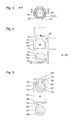
- FIG. 2 shows a schematic sectional view of an embodiment of the flexible portion 46 of the transfer device 40 from FIG. 1 .
- the section plane AA of FIG. 2 is parallel to the drawing plane of the FIG. 1 and in particular includes the longitudinal axis 18 of the shaft 14 and the longitudinal axis 38 of the tool 30.
- the flexible portion 46 comprises a plurality of identical transfer members 50, 60, whose longitudinal axes 58, 68 also in the sectional plane of the AA FIG. 2 lie.
- Each transmission member 50, 60 comprises a convex coupling portion 51, 61 and a concave coupling portion 55, 65.
- the convex coupling portions 51, 61 each have a substantially circular cross section.
- Each transmission member 50, 60 has between the convex coupling portion 51, 61 and the concave coupling portion 55, 65 a taper or a neck 52, 62 and a circumferential groove 53, 63 on.
- the concave coupling sections 55, 65 comprise recesses 56, 66, each having a substantially rectangular cross-section in the sectional plane A-A and surrounded by a wall 57, 67.
- Each concave coupling portion 55, 65 further includes a sleeve 70.
- Each sleeve 70 has a substantially cylindrical wall 74 which surrounds the wall 57, 67 in a shell shape around the recess 56, 66.
- the sleeve 70 also has a radially inwardly projecting collar 76.
- the sleeves 70 are joined to the concave coupling portions 55, 65, in particular welded.
- the convex coupling section 51 engages on a first transmission element 50 in the concave coupling section 65 on a second, adjacent transmission element 60.
- the collar 76 on the sleeve 70 of the concave coupling portion 65 of the second transmission member 60 partially engages the groove 53 on the first transmission member 50 and abuts a shoulder-shaped portion 54 on the convex coupling portion 51 of the first transmission member 50.
- the sliding surface on the collar 76 provided for abutment with the shoulder-shaped region 54 on the convex coupling section 51 of the first transmission element 50 has, in particular, the shape of an annular section of a spherical surface corresponding to the cross-section of the convex coupling section 51 that is substantially spherical in the sectional plane A-A.
- FIG. 3 shows a further schematic sectional view of the flexible portion 46 from FIG. 2 ,
- the location of in FIG. 3 shown sectional plane BB perpendicular to the longitudinal axis 68 of a transmission member 60 is in FIG. 2 indicated.
- the location of in FIG. 2 shown section plane AA is in FIG. 3 indicated.
- both the convex coupling portion 51 and the inner surface of the wall 67 each have a substantially hexagonal cross section.
- the corresponding, substantially hexagonal cross-sections of the convex coupling portion 51 of the first transmission member 50 and the wall 67 of the concave coupling portion 65 of the second transmission member 60 effect a positive coupling of the transmission members 50, 60, which allows a transmission of torque between the transmission members 50, 60 ,
- the outer surface of the wall 67 and the wall 74 of the sleeve 70 each have substantially the shape of a circular cylinder jacket. Deviating therefrom, the sleeve 70 has a slot 78 whose width in the sectional plane BB at least as large as the diameter of the neck 52 (see. FIG. 2 ). In dashed line, the radially inner contour of the collar 76 of the sleeve 70 and the continuation of the slot 78 in the collar 76 is shown. The collar 76 thus does not have the shape of a closed circular ring but deviating therefrom a slot 78 corresponding gap.
- FIG. 4 shows a schematic sectional view of a first transmission member 50 and a sleeve 70 of a second transmission member, the other components in FIG. 4 are not visible.
- the cutting plane of the FIG. 4 is perpendicular to the section plane AA of FIG. 2 and perpendicular to the sectional plane BB of the FIG. 3 and contains the longitudinal axis 58 of the transfer member 50.
- the sectional plane of the FIG. 4 in particular runs in the middle of the slot 78 in the sleeve 70 and parallel to its edges.
- the transmission member 50 is shown with solid lines and hatched cross-sectional area in an initial position in which the longitudinal axis 58 of the transmission member 50 is perpendicular to the longitudinal axis of the sleeve 70. From this initial position, the convex coupling portion 51 of the transmission member 50 is inserted with the indicated by the straight arrow pure translational motion of the first end 71 in the sleeve 70 until the convex coupling portion 51 of the transmission member 50 on the collar 76 of the sleeve 70 substantially abuts and the neck 52 of the transmission member 50 is disposed in the slot 78 in the sleeve 70.
- the configuration achieved in this way is indicated by dashed contours.
- the transmission member 50 thereafter about an axis perpendicular to the plane of the FIG. 4 and thereby pivoted about the convex coupling portion 51 until the longitudinal axis of the transmission member 50 is substantially parallel to the longitudinal axis of the sleeve 70.
- the configuration thus achieved is also indicated by dashed contours.
- the neck 52 of the transmission member 50 is no longer disposed in the slot 78 in the sleeve 70 but substantially at the center of the collar 76 at the second end 72 of the sleeve 70.
- FIG. 5 showed a further schematic sectional view of the transfer member 50 and the sleeve 70 from FIG. 4 in the configuration, which at the end of the basis of the FIG. 4 described movement is present.
- the transmission member 50 and the sleeve 70 are shown together with another transmission member 60.
- a movement of the transfer member 50 together with the sleeve 70 is indicated relative to the further transfer member 60.
- the convex coupling portion 51 of the transmission member 50 is inserted into the recess 66 on the further transmission member 60.
- the sleeve 70 is slipped over the wall 67 around the recess 66 on the further transmission member 60 and the wall 67 is inserted into the sleeve 70.
- the sleeve 70 and the further transmission member 60 joined, in particular by welding, soldering or gluing.
- FIG. 6 shows a schematic sectional view of another embodiment of the flexible portion 46 of the transfer device 40 from FIG. 1 .
- the cutting plane of the FIG. 6 corresponds to the cutting plane of FIG. 2 ,
- FIG. 6 differs from the embodiment of FIGS. 2 to 5 in that not all transmission elements are the same. Instead, transfer members 80, 90 of two different types or types are provided, which are arranged alternately.
- a transmission member 80 of the first type has two convex coupling portions 81, 83 with a neck 82 between the convex coupling portions.
- a transmission member 90 of the second type has two concave coupling portions 91, 93.
- Each individual convex coupling portion 81, 83 of a transmission member 80 of the first type corresponds in shape and function to the convex coupling portion 51, 61 of a transmission member 50, 60 of the embodiment of FIGS FIGS. 2 to 5
- Each individual concave coupling portion 91, 93 of a transmission member 90 of the second type corresponds in terms of spatial shape and function of the concave coupling portion 55, 65 of a transmission member 50, 60 of the embodiment of the FIGS. 2 to 5
- each transfer member 90 of the second type has two sleeves 70.
- the sleeves correspond to the embodiment of FIGS. 2 to 5 .
- the form-fitting articulated coupling between a convex coupling portion 81, 83 of a transmission member of the first type and a concave coupling portion 91, 93 of a transmission member 90 of the second type corresponds to the positive mechanical coupling between a convex coupling portion 51 of a transmission member and a concave coupling portion 65 of an adjacent transmission member 60th at the top of the basis of the FIGS. 2 to 5 illustrated embodiment.
- This in FIG. 6 illustrated embodiment of the flexible portion 46 of Transfer device 40 therefore allows as well as the above based on the FIGS. 2 to 5 illustrated embodiment, a transmission of compressive and tensile forces and torques. Also, the production of the flexible portion 46 according to the in FIG. 6 illustrated embodiment, according to the above with reference to the FIGS. 4 and 5 for the embodiment of FIGS. 2 to 5 shown procedures.
- FIG. 7 shows a schematic flow diagram of a method for producing a transmission device. Although the method is also used to manufacture a transfer device having features different from those described above with reference to FIGS FIGS. 1 to 6 illustrated, is suitable, hereinafter by way of example reference numerals from the FIGS. 1 to 6 used to facilitate understanding.
- a plurality of transmission elements 50, 60; 80, 90 each having two coupling portions 51, 61, 55, 65; 81, 83, 91, 93 are provided.
- the provision of the plurality of transmission members comprises providing 102 a sleeve 70 as part of one of the transmission members 50, 60; 80, 90.
- the sleeve 70 provided in the second step 102 has a slot 78 extending from the first end 71 to the second end 72 of the sleeve 70.
- the sleeve 70 has a radially inwardly projecting collar 76 on the second end 72 of the sleeve 70.
- the third step 103 for example, as above based on the FIG. 4 shown performed.
- a fourth step 104 the convex coupling portion 51; 81, 83 on the first transmission member 50; 80 in the concave coupling portion 65; 91, 93 on the second transmission member 60; 90 introduced.
- the concave coupling section 65; 91, 93 on the second transmission member 60; 90 inserted into the sleeve 70.
- a fifth step 105 the sleeve 70 with the second transmission member 60; 90 joined, in particular welded, soldered or glued.
Landscapes
- Health & Medical Sciences (AREA)
- Engineering & Computer Science (AREA)
- General Engineering & Computer Science (AREA)
- Surgery (AREA)
- Life Sciences & Earth Sciences (AREA)
- Mechanical Engineering (AREA)
- Oral & Maxillofacial Surgery (AREA)
- Medical Informatics (AREA)
- Heart & Thoracic Surgery (AREA)
- Molecular Biology (AREA)
- Animal Behavior & Ethology (AREA)
- General Health & Medical Sciences (AREA)
- Public Health (AREA)
- Veterinary Medicine (AREA)
- Biomedical Technology (AREA)
- Nuclear Medicine, Radiotherapy & Molecular Imaging (AREA)
- Ophthalmology & Optometry (AREA)
- Surgical Instruments (AREA)
Abstract
Description
- Die vorliegende Erfindung ist auf eine Übertragungseinrichtung zum Übertragen einer Kraft und eines Drehmoments zwischen einer Handhabungseinrichtung und einem Werkzeug eines medizinischen Instruments und auf ein Verfahren zum Herstellen einer Übertragungseinrichtung bezogen.
- Die Erwartungen an medizinische Instrumente für mikroinvasive Eingriffe steigen beständig. Bereits in Vielfalt angeboten und weit verbreitet sind medizinische Instrumente mit einem Werkzeug mit Greif- oder Schneidefunktion am distalen Ende, bei denen das Werkzeug um die Längsachse des Schafts rotierbar ist. Die Greif- oder Schneidefunktion und die Rotation des Werkzeugs sind beispielsweise mittels einer einzigen Übertragungsstange steuerbar, die Längskräfte und Drehmomente überträgt. Hinzu kommt in neuerer Zeit eine Abwinkelbarkeit des Schafts an einem Gelenk proximal des Werkzeugs. Dies setzt eine Flexibilität der Übertragungsstange im Bereich des Gelenks voraus.
- In der
DE 39 23 609 A1 ist eine Winkelantriebsvorrichtung mit einer Vielzahl von miteinander in Eingriff stehenden Bewegungsübertragungssegmenten beschrieben. Jedes Bewegungsübertragungssegment umfasst einen Kopfabschnitt und einen Fassungsabschnitt mit jeweils polygonalem Querschnitt. Der Kopfabschnitt eines Bewegungsübertragungssegments greift in einen Fassungsabschnitt eines benachbarten Bewegungsübertragungssegments ein. Die Winkelantriebsvorrichtung ermöglicht jedoch keine Übertragung von Zugkräften. - Eine Aufgabe der vorliegenden Erfindung besteht darin, eine verbesserte Übertragungseinrichtung zum Übertragen einer Kraft und eines Drehmoments zwischen einer Handhabungseinrichtung und einem Werkzeug eines medizinischen Instruments, ein verbessertes Werkzeug für ein medizinisches Instrument, ein verbessertes medizinisches Instrument und ein verbessertes Verfahren zum Herstellen einer Übertragungseinrichtung zu schaffen.
- Diese Aufgabe wird durch die Gegenstände der unabhängigen Ansprüche gelöst.
- Weiterbildungen sind in den abhängigen Ansprüchen angegeben.
- Eine Übertragungseinrichtung zum Übertragen einer Kraft und eines Drehmoments zwischen einer Handhabungseinrichtung und einem Werkzeug eines medizinischen Instruments umfasst miteinander gelenkig verbundene Übertragungsglieder, wobei jeweils ein konvexer Kopplungsabschnitt eines ersten Übertragungsglieds in einem konkaven Kopplungsabschnitts eines benachbarten zweiten Übertragungsglieds derart formschlüssig gehalten ist, dass eine Rotation des ersten Übertragungsglieds um seine Längsachse eine Rotation des zweiten Übertragungsglieds um seine Längsachse bewirkt, wobei jeweils ein konvexer Kopplungsabschnitt eines ersten Übertragungsglieds in einem konkaven Kopplungsabschnitt eines benachbarten zweiten Übertragungsglieds derart formschlüssig gehalten ist, dass eine Zugkraft zwischen dem ersten Übertragungsglied und dem zweiten Übertragungsglied übertragbar ist.
- Die Übertragungseinrichtung ist insbesondere für ein medizinisches Instrument für mikroinvasiv-chirurgische Eingriffe ausgebildet und weist einen Schaft zwischen Handhabungseinrichtung und Werkzeug auf. Die Übertragungseinrichtung ist zum Übertragen eines Drehmoments und zum Übertragen von sowohl Druck- als auch Zugkräften in dem Schaft vorgesehen und ausgebildet. Die gelenkig verbundenen Übertragungsglieder sind insbesondere dazu vorgesehen und ausgebildet, in einem gekrümmten oder krümmbaren bzw. flexiblen oder elastischen Bereich des Schafts angeordnet zu werden.
- Damit eine Rotation eines ersten Übertragungsglieds um seine Längsachse eine Rotation eines zweiten Übertragungsglieds um seine Längsachse bewirkt, sind die Übertragungsglieder insbesondere torsionssteif miteinander gekoppelt bzw. in einer zur Übertragung von Drehmomenten geeigneten Weise miteinander gekoppelt. Insbesondere weisen der konvexe Kopplungsabschnitt eines Übertragungsglieds und der konkave Kopplungsabschnitt eines benachbarten Übertragungsglieds jeweils korrespondierende polygonale Querschnitte auf, beispielsweise sechseckige Querschnitte.
- Mitteils einer Übertragungseinrichtung mit den beschriebenen Merkmalen können nicht nur Drehmomente und Druckkräfte, sondern auch Zugkräfte übertragen werden. Dies kann beispielsweise eine Steuerung einer Rotation und sowohl eines Öffnens als auch eines Schließens von Maulteilen eines Werkzeugs am distalen Ende eines krümmbaren oder abwinkelbaren Schafts ermöglichen, wie es von medizinischen Instrumenten mit starrem geraden Schaft bereits bekannt ist.
- Bei einer Übertragungseinrichtung, wie sie hier beschrieben ist, sind insbesondere am konvexen Kopplungsabschnitt eines ersten Übertragungsglieds ein erster Haltebereich und am konkaven Kopplungsabschnitt eines benachbarten zweiten Übertragungsglieds ein zweiter Haltebereich vorgesehen und der erste Haltebereich und der zweite Haltebereich formschlüssig miteinander verbunden, um eine Zugkraft zwischen dem ersten Übertragungsglied und dem zweiten Übertragungsglied aufzunehmen.
- Bei einer Übertragungseinrichtung, wie sie hier beschrieben ist, ist bezogen auf eine Schnittebene, die die Längsachse des ersten Übertragungsglieds enthält, insbesondere der erste Haltebereich zu einem konkaven Bereich der Kontur des Übertragungsglieds benachbart, wobei der zweite Haltebereich eine im Wesentlichen konvexe Kontur aufweist.
- Die Kontur des ersten Haltebereichs selbst in der Schnittebene ist insbesondere konvex. Der zweite Haltebereich kann eine Gleitfläche aufweisen, deren Gestalt an die Gestalt der Oberfläche des ersten Haltebereichs angepasst ist bzw. zu dieser korrespondiert. Die im Wesentlichen konvexe Kontur des zweiten Haltebereichs kann im Bereich der Gleitfläche konkav sein.
- Bei einer Übertragungseinrichtung, wie sie hier beschrieben ist, wird der erste Haltebereich am ersten Übertragungsglied insbesondere durch den Rand einer Nut gebildet, wobei der zweite Haltebereich am zweiten Übertragungsglied die Gestalt eines Kragens, der in die Nut am ersten Übertragungsglied eingreift, aufweist.
- Die Nut ist insbesondere eine umlaufende, den gesamten Umfang des ersten Übertragungsglieds (insbesondere in einer Ebene senkrecht zu dessen Längsachse) einnehmende, nach radial außen offene Nut. Die Nut bildet insbesondere den oben genannten konkaven Bereich der Kontur des ersten Übertragungsglieds in der die Längsachse enthaltenen Schnittebene. Der erste Haltebereich wird insbesondere durch einen schulterförmigen Bereich am ersten Übertragungsglied gebildet, der gleichzeitig ein Randbereich oder eine Flanke der Nut ist. Der zweite Haltebereich am zweiten Übertragungsglied weist insbesondere die Gestalt eines umlaufenden bzw. im Wesentlichen geschlossenen und nach radial innen ragenden Kragens auf. Der Kragen weist insbesondere die Gestalt eines vollständigen oder fast vollständigen Kreisrings auf.
- Bei einer Übertragungseinrichtung, wie sie hier beschrieben ist, ist der erste Haltebereich insbesondere durch eine Verjüngung des ersten Übertragungsglieds an einer von dem zweiten Übertragungsglied abgewandten Seite des konvexen Kopplungsabschnitts des ersten Übertragungsglieds gebildet.
- Bei einer Übertragungseinrichtung, wie sie hier beschrieben ist, bildet insbesondere eine Hülse, die den konkaven Kopplungsabschnitt umgibt, den nach radial innen ragenden Kragen.
- Den nach radial innen ragenden Kragen an einer Hülse vorzusehen, kann eine kostengünstige Fertigung ermöglichen, bei der beispielsweise der konvexe Kopplungsabschnitt für ein erstes Übertragungsglied zunächst in der Hülse angeordnet und dann mit dem ersten Übertragungsglied gefügt wird, wonach die Hülse mit dem zweiten Übertragungsglied gefügt wird.
- Bei einer Übertragungseinrichtung, wie sie hier beschrieben ist, umfasst die Hülse insbesondere einen Schlitz, der parallel zur Längsachse des zweiten Übertragungsglieds ist.
- Bei einer Übertragungseinrichtung, wie sie hier beschrieben ist, ist der erste Haltebereich am ersten Übertragungsglied insbesondere durch eine Verjüngung des ersten Übertragungsglieds an einer von dem zweiten Übertragungsglied abgewandten Seite des konvexen Kopplungsabschnitts gebildet, wobei der Schlitz in der Hülse eine Breite aufweist, die nicht kleiner ist als eine minimale Breite der Verjüngung.
- Der konvexe Kopplungsabschnitt kann einstückig mit anderen Bereichen des ersten Übertragungsglieds gebildet werden, beispielsweise mittels spanabhebender Verfahren. Danach kann die Verjüngung zwischen dem konvexen Kopplungsabschnitt und dem Rest des ersten Übertragungsglieds durch den Schlitz der Hülse hindurchgeführt werden, bis der Kragen an der Hülse den konvexen Kopplungsabschnitt hintergreift. Danach kann die Hülse mit dem zweiten Übertragungsglied gefügt werden. Die Verjüngung weist insbesondere die Gestalt eines Halses bzw. einer Taille auf.
- Ein Werkzeug für ein medizinisches Instrument umfasst eine Übertragungseinrichtung, wie sie hier beschrieben ist.
- Ein medizinisches Instrument umfasst eine Übertragungseinrichtung, wie sie hier beschrieben ist.
- Bei einem Verfahren zum Herstellen einer Übertragungseinrichtung werden mehrere Übertragungsglieder mit jeweils zwei Kopplungsabschnitten bereitgestellt, wobei eines der mehreren Übertragungsglieder eine Hülse mit einem sich vom ersten Ende zum zweiten Ende der Hülse erstreckenden Schlitz und einen nach radial innen ragenden Kragen am zweiten Ende der Hülse aufweist. Eine Verjüngung an einem konvexen Kopplungsabschnitt an einem ersten Übertragungsglied wird vom ersten Ende durch den Schlitz bis zum zweiten Ende der Hülse hindurchgeführt. Ein konkaver Kopplungsabschnitt an einem zweiten Übertragungsglied wird in die Hülse eingeführt, wobei der konvexe Kopplungsabschnitt am ersten Übertragungsglied in den konkaven Kopplungsabschnitt am zweiten Übertragungsglied eingeführt wird. Die Hülse wird mit dem zweiten Übertragungsglied gefügt.
- Das beschriebene Verfahren kann eine einfache und kostengünstige Herstellung einer Übertragungseinrichtung, insbesondere einer Übertragungseinrichtung mit den oben beschriebenen Merkmalen, ermöglichen. Insbesondere sind alle Übertragungsglieder gleich und weisen jeweils eine Hülse mit einem sich vom ersten Ende zum zweiten Ende der Hülse erstreckenden Schlitz auf. Alternativ sind zwei oder mehr verschiedene Typen von Übertragungsgliedern vorgesehen, wobei jedes einzelne Übertragungsglied an jedem Ende, an einem Ende oder an keinem Ende eine Hülse mit einem nach radial innen ragenden Kragen aufweisen kann.
- Nachfolgend werden Ausführungsformen anhand der beigefügten Figuren näher erläutert. Es zeigen:
- Figur 1
- eine schematische Darstellung eines medizinischen Instruments;
- Figur 2
- eine schematische Schnittdarstellung eines flexiblen Abschnitts einer Übertragungseinrichtung;
- Figur 3
- eine weitere schematische Schnittdarstellung des flexiblen Abschnitts aus
Figur 2 ; - Figur 4
- eine weitere schematische Schnittdarstellung von Kopplungsgliedern aus den
Figuren 2 und3 ; - Figur 5
- eine weitere schematische Schnittdarstellung der Kopplungsglieder aus
Figur 4 ; - Figur 6
- eine schematische Schnittdarstellung eines weiteren flexiblen Abschnitts einer Übertragungseinrichtung;
- Figur 7
- ein schematisches Flussdiagramm.
-
Figur 1 zeigt eine schematische Darstellung eines medizinischen Instruments 10 mit einem proximalen Ende 11 und einem distalen Ende 12, zwischen denen sich ein Schaft 14 mit einem Gelenk 16 erstreckt. Der Schaft 14 ist proximal des Gelenks 16 insbesondere starr und gerade und weist eine Längsachse 18 auf. Das Gelenk 16 wird durch einen flexiblen oder elastischen Abschnitt des Schafts 14 oder durch eine gelenkige Verbindung zweier jeweils starrer Abschnitte des Schafts 14 gebildet. - Am proximalen Ende 11 weist das medizinische Instrument 10 eine Handhabungseinrichtung 20 mit einem feststehenden Griffteil 21 und einem bewegbaren Griffteil 22 auf. Der bewegbare Griffteil 22 ist insbesondere um eine Schwenkachse senkrecht zur Zeichenebene der
Figur 1 schwenkbar. Eine erste Position des bewegbaren Griffteils 22 ist inFigur 1 mit durchgezogenen Linien dargestellt. Eine zweite Position des bewegbaren Griffteils 22 ist inFigur 1 mit gestrichelten Linien dargestellt. Ferner weist die Handhabungseinrichtung 20 ein Drehrad 23 auf, das um die Längsachse 18 des Schafts 14 rotierbar ist. - Am distalen Ende 12 des medizinischen Instruments 10 ist ein Werkzeug 30 mit zwei schwenkbaren Maulteilen 31, 32 vorgesehen. In
Figur 1 ist durch zwei Pfeile angedeutet, dass die schwenkbaren Maulteile 31, 32 jeweils um eine zugeordnete Schwenkachse senkrecht zur Zeichenebene derFigur 1 zwischen geschlossenen Positionen und offenen Positionen schwenkbar sind. Die geschlossenen Positionen sind inFigur 1 mit durchgezogenen Linien dargestellt, die offenen Positionen sind inFigur 1 mit gestrichelten Linien dargestellt. Ferner ist das Werkzeug 30 mit den Maulteilen 31, 32 um eine Rotationsachse 38 rotierbar, die insbesondere die Längsachse des Werkzeugs 30 ist. - Die Handhabungseinrichtung 20 am proximalen Ende 11 und das Werkzeug 30 am distalen Ende 12 des medizinischen Instruments 10 sind mittels einer Übertragungseinrichtung 40, insbesondere einer Übertragungsstange, im Schaft 14 gekoppelt. Die Übertragungseinrichtung 40 umfasst einen flexiblen Abschnitt 46, der unten mit Bezug auf die
Figuren 2 bis 6 dargestellt ist. Die Übertragungseinrichtung 40 koppelt insbesondere den bewegbaren Griffteil 22 der Handhabungseinrichtung 20 und das Drehrad 23 an der Handhabungseinrichtung 20 einerseits mit dem Werkzeug 30 andererseits. - Insbesondere wird eine manuelle Bewegung des bewegbaren Griffteils 22 an der Handhabungseinrichtung 20 durch eine axiale Bewegung der Übertragungseinrichtung 40 parallel zur Längsachse 18 des medizinischen Instruments 10 und distal des flexiblen Abschnitts 46 parallel zu der Rotationsachse 38 des Werkzeugs 30 zu den Maulteilen 31, 32 übertragen und bewirkt öffnende oder schließende Schwenkbewegen der Maulteile 31, 32. Eine Rotation des Drehrads 23 um die Längsachse 18 wird durch eine Rotation der Übertragungseinrichtung 40 um die Längsachse 18 und distal des flexiblen Abschnitts 46 um die Längsachse 38 des Werkzeugs 30 zu dem Werkzeug 30 übertragen und bewirkt eine Rotation des Werkzeugs 30 um seine Rotationsachse 38.
- Für eine spiel- und reibungsarme Übertragung von Längskräften und Drehmomenten ist die Übertragungseinrichtung 40 im Schaft 14 spiel- und reibungsarm gelagert und hinsichtlich Druck- und Zugkräften steif bzw. unelastisch und ferner torsionssteif bzw. steif hinsichtlich einer Torsion um ihre Längsachse ausgebildet. Dies gilt insbesondere auch für den flexiblen Abschnitt 46.
-
Figur 2 zeigt eine schematische Schnittdarstellung eines Ausführungsbeispiels des flexiblen Abschnitts 46 der Übertragungseinrichtung 40 ausFigur 1 . Die Schnittebene A-A derFigur 2 ist parallel zur Zeichenebene derFigur 1 und enthält insbesondere die Längsachse 18 des Schafts 14 und die Längsachse 38 des Werkzeugs 30. Der flexible Abschnitt 46 umfasst eine Mehrzahl baugleicher Übertragungsglieder 50, 60, deren Längsachsen 58, 68 ebenfalls in der Schnittebene der A-A derFigur 2 liegen. - Jedes Übertragungsglied 50, 60 umfasst einen konvexen Kopplungsabschnitt 51, 61 und einen konkaven Kopplungsabschnitt 55, 65. In der Schnittebene A-A der
Figur 2 weisen die konvexen Kopplungsabschnitte 51, 61 jeweils einen im Wesentlichen kreisförmigen Querschnitt auf. Jedes Übertragungsglied 50, 60 weist zwischen dem konvexen Kopplungsabschnitt 51, 61 und dem konkaven Kopplungsabschnitt 55, 65 eine Verjüngung bzw. einen Hals 52, 62 bzw. eine umlaufende Nut 53, 63 auf. - Die konkaven Kopplungsabschnitte 55, 65 umfassen Ausnehmungen 56, 66, die in der Schnittebene A-A jeweils einen im Wesentlichen rechteckigen Querschnitt aufweisen und von einer Wand 57, 67 umgeben sind. Jeder konkave Kopplungsabschnitt 55, 65 umfasst ferner eine Hülse 70. Jede Hülse 70 weist eine im Wesentlichen zylindrische Wand 74 auf, die die Wand 57, 67 um die Ausnehmung 56, 66 mantelförmig umgibt. Die Hülse 70 weist ferner einen nach radial innen ragenden Kragen 76 auf. Die Hülsen 70 sind mit den konkaven Kopplungsabschnitten 55, 65 gefügt, insbesondere geschweißt.
- Es greift jeweils der konvexe Kopplungsabschnitt 51 an einem ersten Übertragungsglied 50 in den konkaven Kopplungsabschnitt 65 an einem zweiten, benachbarten Übertragungsglied 60 ein. Der Kragen 76 an der Hülse 70 des konkaven Kopplungsabschnitts 65 des zweiten Übertragungsglieds 60 greift teilweise in die Nut 53 am ersten Übertragungsglied 50 ein und liegt an einem schulterförmigen Bereich 54 am konvexen Kopplungsabschnitt 51 des ersten Übertragungsglieds 50 an. Die zum Anliegen an dem schulterförmigen Bereich 54 am konvexen Kopplungsabschnitt 51 des ersten Übertragungsglieds 50 vorgesehene Gleitfläche am Kragen 76 weist entsprechend dem in der Schnittebene A-A im Wesentlichen kugelförmigen Querschnitt des konvexen Kopplungsabschnitts 51 insbesondere die Gestalt eines ringförmigen Ausschnitts einer Kugeloberfläche auf.
- Durch den zumindest teilweisen Eingriff des Kragens 76 eines Übertragungsglieds 60 in die Nut 53 am benachbarten Übertragungsglied 50 bzw. durch das Anliegen des Kragens 76 eines Übertragungsglieds 60 am schulterförmigen Bereich 54 am konvexen Kopplungsabschnitt 51 des benachbarten Übertragungsglieds 50 sind nicht nur Druckkräfte, sondern auch Zugkräfte zwischen den Übertragungsgliedern 50, 60 übertragbar. Damit sind auch durch den gesamten flexiblen Abschnitt 46 der Übertragungseinrichtung 40 Zugkräfte übertragbar. Die Darstellung in
Figur 2 zeigt, dass die formschlüssige Kopplung der Übertragungsglieder 50, 60 gelenkig ist. Deshalb können die Längsachsen 58, 68 benachbarter Übertragungsglieder 50, 60 innerhalb eines vorbestimmten Winkelintervalls relativ zueinander gekippt werden. -
Figur 3 zeigt eine weitere schematische Schnittdarstellung des flexiblen Abschnitts 46 ausFigur 2 . Die Lage der inFigur 3 dargestellten Schnittebene B-B senkrecht zur Längsachse 68 eines Übertragungsglieds 60 ist inFigur 2 angedeutet. Die Lage der inFigur 2 dargestellten Schnittebene A-A ist inFigur 3 angedeutet. - In der Schnittebene B-B weisen sowohl der konvexe Kopplungsabschnitt 51 als auch die innere Oberfläche der Wand 67 jeweils einen im Wesentlichen sechseckigen Querschnitt auf. Die einander korrespondierenden, im Wesentlichen sechseckigen Querschnitte des konvexen Kopplungsabschnittes 51 des ersten Übertragungsglieds 50 und der Wand 67 des konkaven Kopplungsabschnitts 65 des zweiten Übertragungsglieds 60 bewirken eine formschlüssige Kopplung der Übertragungsglieder 50, 60, die eine Übertragung eines Drehmoments zwischen den Übertragungsgliedern 50, 60 ermöglicht.
- Die äußere Oberfläche der Wand 67 und die Wand 74 der Hülse 70 weisen jeweils im Wesentlichen die Gestalt eines Kreiszylindermantels auf. Abweichen davon weist die Hülse 70 einen Schlitz 78 auf, dessen Breite in der Schnittebene B-B mindestens so groß wie der Durchmesser des Halses 52 (vgl.
Figur 2 ) ist. In gestrichelter Linie ist die radial innere Kontur des Kragens 76 der Hülse 70 sowie der Fortsetzung des Schlitzes 78 in den Kragen 76 hinein dargestellt. Der Kragen 76 weist also nicht die Gestalt eines geschlossenen Kreisrings sondern abweichend davon eine dem Schlitz 78 entsprechende Lücke auf. -
Figur 4 zeigt eine schematische Schnittdarstellung eines ersten Übertragungsglieds 50 und einer Hülse 70 eines zweiten Übertragungsglieds, dessen weitere Bestandteile inFigur 4 nicht sichtbar sind. Die Schnittebene derFigur 4 ist senkrecht zur Schnittebene A-A derFigur 2 und senkrecht zur Schnittebene B-B derFigur 3 und enthält die Längsachse 58 des Übertragungsglieds 50. Die Schnittebene derFigur 4 verläuft insbesondere in der Mitte des Schlitzes 78 in der Hülse 70 und parallel zu dessen Rändern. - Das Übertragungsglied 50 ist mit durchgezogenen Linien und schraffierter Querschnittsfläche in einer anfänglichen Position gezeigt, in der die Längsachse 58 des Übertragungsglieds 50 senkrecht zur Längsachse der Hülse 70 ist. Von dieser anfänglichen Position aus wird der konvexe Kopplungsabschnitt 51 des Übertragungsglieds 50 mit der durch den geraden Pfeil angedeuteten reinen Translationsbewegung von deren ersten Ende 71 aus in die Hülse 70 eingeführt bis der konvexe Kopplungsabschnitt 51 des Übertragungsglieds 50 am Kragen 76 der Hülse 70 im Wesentlichen anliegt und der Hals 52 des Übertragungsglieds 50 in dem Schlitz 78 in der Hülse 70 angeordnet ist. Die so erreichte Konfiguration ist durch gestrichelte Konturen angedeutet.
- Wie in
Figur 4 durch einen gekrümmten Pfeil angedeutet ist, wird das Übertragungsglied 50 danach um eine Achse senkrecht zur Zeichenebene derFigur 4 und dabei um den konvexen Kopplungsabschnitt 51 geschwenkt bis die Längsachse des Übertragungsglieds 50 im Wesentlichen parallel zur Längsachse der Hülse 70 ist. Die so erreichte Konfiguration ist ebenfalls durch gestrichelte Konturen angedeutet. In dieser Konfiguration ist der Hals 52 des Übertragungsglieds 50 nicht mehr im Schlitz 78 in der Hülse 70, sondern im Wesentlichen in der Mitte des Kragens 76 am zweiten Ende 72 der Hülse 70 angeordnet. -
Figur 5 zeigte eine weitere schematische Schnittdarstellung des Übertragungsglieds 50 und der Hülse 70 ausFigur 4 in der Konfiguration, die am Ende der anhand derFigur 4 beschriebenen Bewegung vorliegt. Das Übertragungsglied 50 und die Hülse 70 sind zusammen mit einem weiteren Übertragungsglied 60 dargestellt. Durch einen geraden Pfeil ist eine Bewegung des Übertragungsglieds 50 zusammen mit der Hülse 70 relativ zum weiteren Übertragungsglied 60 angedeutet. Bei dieser Bewegung wird der konvexe Kopplungsabschnitt 51 des Übertragungsglieds 50 in die Ausnehmung 66 am weiteren Übertragungsglied 60 eingeführt. Gleichzeitig wird die Hülse 70 über die Wand 67 um die Ausnehmung 66 am weiteren Übertragungsglied 60 gestülpt bzw. die Wand 67 in die Hülse 70 eingeführt. Wenn die inFigur 2 dargestellte Konfiguration erreicht ist, werden die Hülse 70 und das weitere Übertragungsglied 60 gefügt, insbesondere durch Schweißen, Löten oder Kleben. -
Figur 6 zeigt eine schematische Schnittdarstellung eines weiteren Ausführungsbeispiels des flexiblen Abschnitts 46 der Übertragungseinrichtung 40 ausFigur 1 . Die Schnittebene derFigur 6 entspricht der Schnittebene derFigur 2 . - Das Ausführungsbeispiel der
Figur 6 unterscheidet sich vom Ausführungsbeispiel derFiguren 2 bis 5 dadurch, dass nicht alle Übertragungsglieder gleich sind. Stattdessen sind Übertragungsglieder 80, 90 zweier unterschiedlicher Typen bzw. Bauarten vorgesehen, die abwechselnd angeordnet sind. Ein Übertragungsglied 80 des ersten Typs weist zwei konvexe Kopplungsabschnitte 81, 83 mit einer Verjüngung bzw. einem Hals 82 zwischen den konvexen Kopplungsabschnitten auf. Ein Übertragungsglied 90 des zweiten Typs weist zwei konkave Kopplungsabschnitte 91, 93 auf. - Jeder einzelne konvexe Kopplungsabschnitt 81, 83 eines Übertragungsglieds 80 des ersten Typs entspricht hinsichtlich Gestalt und Funktion dem konvexen Kopplungsabschnitt 51, 61 eines Übertragungsglieds 50, 60 des Ausführungsbeispiels aus den
Figuren 2 bis 5 . Jeder einzelne konkave Kopplungsabschnitt 91, 93 eines Übertragungsglieds 90 des zweiten Typs entspricht hinsichtlich räumlicher Gestalt und Funktion dem konkaven Kopplungsabschnitt 55, 65 eines Übertragungsglieds 50, 60 des Ausführungsbeispiels aus denFiguren 2 bis 5 . Insbesondere weist deshalb jedes Übertragungsglied 90 des zweiten Typs zwei Hülsen 70 auf. Die Hülsen entsprechen dem Ausführungsbeispiel derFiguren 2 bis 5 . - Die formschlüssige gelenkige Kopplung zwischen einem konvexen Kopplungsabschnitt 81, 83 eines Übertragungsglieds des ersten Typs und einem konkaven Kopplungsabschnitt 91, 93 eines Übertragungsglieds 90 des zweiten Typs entspricht der formschlüssigen mechanischen Kopplung zwischen einem konvexen Kopplungsabschnitt 51 eines Übertragungsglieds und einem konkaven Kopplungsabschnitt 65 eines benachbarten Übertragungsglieds 60 bei dem oben anhand der
Figuren 2 bis 5 dargestellten Ausführungsbeispiel. Das inFigur 6 dargestellte Ausführungsbeispiel des flexiblen Abschnitts 46 der Übertragungseinrichtung 40 ermöglicht deshalb ebenso wie das oben anhand derFiguren 2 bis 5 dargestellte Ausführungsbeispiel eine Übertragung von Druck- und Zugkräften sowie von Drehmomenten. Auch die Herstellung des flexiblen Abschnitts 46 gemäß dem inFigur 6 dargestellten Ausführungsbeispiel kann entsprechend dem oben anhand derFiguren 4 und 5 für das Ausführungsbeispiel derFiguren 2 bis 5 dargestellten Verfahren erfolgen. -
Figur 7 zeigt ein schematisches Flussdiagram eines Verfahrens zum Herstellen einer Übertragungseinrichtung. Obwohl sich das Verfahren auch zum Herstellen einer Übertragungseinrichtung mit Merkmalen, die sich von den oben anhand derFiguren 1 bis 6 dargestellten unterscheidet, eignet, werden nachfolgend beispielhaft Bezugszeichen aus denFiguren 1 bis 6 verwendet, um das Verständnis zu erleichtern. - Bei einem ersten Schritt 101 werden mehrere Übertragungsglieder 50, 60; 80, 90 mit jeweils zwei Kopplungsabschnitten 51, 61, 55, 65; 81, 83, 91, 93 bereitgestellt. Das Bereitstellen der mehreren Übertragungsglieder umfasst ein Bereitstellen 102 einer Hülse 70 als Bestandteil von einem der Übertragungsglieder 50, 60; 80, 90. Die beim zweiten Schritt 102 bereitgestellte Hülse 70 weist einen Schlitz 78 auf, der sich vom ersten Ende 71 zum zweiten Ende 72 der Hülse 70 erstreckt. Ferner weist die Hülse 70 einen nach radial innen ragenden Kragen 76 am zweiten Ende 72 der Hülse 70 auf.
- Bei einem dritten Schritt 103 wird eine Verjüngung bzw. ein Hals 52; 82 an einem konvexen Kopplungsabschnitt 51; 81, 83 an einem Übertragungsglied 50; 80 vom ersten Ende 71 durch den Schlitz 78 bis zum zweiten Ende 72 der Hülse 70 hindurch geführt. Der dritte Schritt 103 wird beispielsweise, wie oben anhand der
Figur 4 dargestellt, durchgeführt. - Bei einem vierten Schritt 104 wird der konvexe Kopplungsabschnitt 51; 81, 83 am ersten Übertragungsglied 50; 80 in den konkaven Kopplungsabschnitt 65; 91, 93 am zweiten Übertragungsglied 60; 90 eingeführt. Dabei wird gleichzeitig der konkave Kopplungsabschnitt 65; 91, 93 am zweiten Übertragungsglied 60; 90 in die Hülse 70 eingeführt. Bei einem fünften Schritt 105 wird die Hülse 70 mit dem zweiten Übertragungsglied 60; 90 gefügt, insbesondere geschweißt, gelötet oder geklebt.
Bezugszeichen 10 medizinisches Instrument 11 proximales Ende des medizinischen Instruments 10 12 distales Ende des medizinischen Instruments 10 14 Schaft des medizinischen Instruments 10 16 Gelenk am Schaft 14 18 Längsachse des medizinischen Instruments 10 20 Handhabungseinrichtung am proximalen Ende 11 des medizinischen Instruments 10 21 feststehendes Griffteil der Handhabungseinrichtung 20 22 bewegbares Griffteil der Handhabungseinrichtung 20 23 Drehrad an der Handhabungseinrichtung 20 30 Werkzeug am distalen Ende 12 des medizinischen Instruments 10 31 erstes Maulteil am Werkzeug 30 32 zweites Maulteil am Werkzeug 30 38 Rotationsachse des Werkzeugs 30 40 Übertragungseinrichtung 46 flexibler Abschnitt der Übertragungseinrichtung 40 50 Übertragungsglied 51 konvexer Kopplungsabschnitt des Übertragungsglieds 60 52 Hals des Übertragungsglieds 50 53 Nut am Übertragungsglied 50 54 schulterförmiger Bereich am konvexen Kopplungsabschnitt 51 55 konkaver Kopplungsabschnitt am Übertragungsglied 50 56 Ausnehmung am konkaven Kopplungsabschnitt 55 57 Wand um Ausnehmung 56 58 Längsachse des Übertragungsglieds 50 60 Übertragungsglied 61 konvexer Kopplungsabschnitt des Übertragungsglieds 60 62 Hals des Übertragungsglieds 60 63 Nut am Übertragungsglied 60 64 schulterförmiger Bereich am konvexen Kopplungsabschnitt 61 65 konkaver Kopplungsabschnitt am Übertragungsglied 60 66 Ausnehmung am konkaven Kopplungsabschnitt 65 67 Wand um Ausnehmung 66 68 Längsachse des Übertragungsglieds 60 70 Hülse des Übertragungsglieds 60 71 erstes Ende der Hülse 70 72 zweites Ende der Hülse 70 74 zylindrische Wand der Hülse 70 76 Rand am zweiten Ende 72 der Hülse 70 78 Schlitz in Hülse 70 80 Übertragungsglied eines ersten Typs 81 erster konvexer Kopplungsabschnitt des Übertragungsglieds 80 82 Hals des Übertragungsglieds 80 83 zweiter konvexer Kopplungsabschnitt des Übertragungsglieds 80 84 schulterförmiger Bereich am ersten konvexen Kopplungsabschnitt 81 88 Längsachse des Übertragungsglieds 80 90 Übertragungsglied eines zweiten Typs 91 erster konkaver Kopplungsabschnitt des Übertragungsglieds 90 93 zweiter konkaver Kopplungsabschnitt des Übertragungsglieds 90 96 Ausnehmung am konkaven Kopplungsabschnitt 95 97 Wand um Ausnehmung 96 98 Längsachse des Übertragungsglieds 90 101 erster Schritt (Bereitstellen) 102 zweiter Schritt (Bereitstellen) 103 dritter Schritt (Hindurchführen) 104 vierter Schritt (Einführen) 105 fünfter Schritt (Fügen)
Claims (10)
- Übertragungseinrichtung (40) zum Übertragen einer Kraft und eines Drehmoments zwischen einer Handhabungseinrichtung (20) und einem Werkzeug (30) eines medizinischen Instruments (10), mit: miteinander gelenkig verbundenen Übertragungsgliedern (50, 60; 80, 90), wobei jeweils ein konvexer Kopplungsabschnitt (51; 81, 83) eines ersten Übertragungsglieds (50; 80) in einem konkaven Kopplungsabschnitt (64; 91, 93) eines benachbarten zweiten Übertragungsglieds (60; 90) derart formschlüssig gehalten ist, dass eine Rotation des ersten Übertragungsglieds (50; 80) um seine Längsachse (58; 88) eine Rotation des zweiten Übertragungsglieds (60; 90) um seine Längsachse (68; 98) bewirkt, wobei jeweils ein konvexer Kopplungsabschnitt (51; 81, 82) eines ersten Übertragungsglieds (50; 80) in einem konkaven Kopplungsabschnitt (64; 91, 93) eines benachbarten zweiten Übertragungsglieds (60; 90) derart formschlüssig gehalten ist, dass eine Zugkraft zwischen dem ersten Übertragungsglied (50; 80) und dem zweiten Übertragungsglied (60; 90) übertragbar ist.
- Übertragungseinrichtung (40) nach einem der vorangehenden Ansprüche, bei der am konvexen Kopplungsabschnitt (51; 81, 83) eines ersten Übertragungsglieds (50; 80) ein erster Haltebereich (54; 84) und am konkaven Kopplungsabschnitt (64; 91, 93) eines benachbarten zweiten Übertragungsglieds (60; 90) ein zweiter Haltebereich (76) vorgesehen sind, der erste Haltebereich (54; 84) und der zweite Haltebereich (76) formschlüssig miteinander verbunden sind, um eine Zugkraft zwischen dem ersten Übertragungsglied (50; 80) und dem zweiten Übertragungsglied (60; 90) aufzunehmen.
- Übertragungseinrichtung (40) nach dem vorangehenden Anspruch, bei der bezogen auf eine Schnittebene, die die Längsachse (58; 88) des ersten Übertragungsglieds (50; 80) enthält, der erste Haltebereich (54; 84) zu einem konkaven Bereich (52; 82) der Kontur des Übertragungsglieds (50; 80) benachbart ist, der zweite Haltebereich (76) eine im Wesentlichen konvexe Kontur aufweist.
- Übertragungseinrichtung (40) nach einem der Ansprüche 2 und 3, bei derder erste Haltebereich (54; 85) am ersten Übertragungsglied (50; 80) durch den Rand einer Nut (53) gebildet wird, der zweite Haltebereich (76) am zweiten Übertragungsglied (60; 90) die Gestalt eines Kragens, der in die Nut (53) am ersten Übertragungsglied (50; 80) eingreift, aufweist.
- Übertragungseinrichtung (40) nach dem vorangehenden Anspruch, bei der eine Hülse (70), die den konkaven Kopplungsabschnitt (64) umgibt, den nach radial innen ragenden Kragen (76) bildet.
- Übertragungseinrichtung (40) nach dem vorangehenden Anspruch, bei der die Hülse (70) einen Schlitz (78) umfasst, der parallel zur Längsachse (68; 98) des zweiten Übertragungsglieds (60; 90) ist.
- Übertragungseinrichtung (40) nach dem vorangehenden Anspruch, bei der der erste Haltebereich (54; 84) am ersten Übertragungsglied (50; 80) durch eine Verjüngung (52; 82) des ersten Übertragungsglieds (50; 80) an einer von dem zweiten Übertragungsglied (60; 90) abgewandten Seite des konvexen Kupplungsabschnitts (51; 81, 83) gebildet ist, der Schlitz (78) in der Hülse (70) eine Breite aufweist, die nicht kleiner ist als eine minimale Breite der Verjüngung (52; 82).
- Werkzeug (30) für ein medizinisches Instrument (10) mit einer Übertragungseinrichtung (40) nach einem der vorangehenden Ansprüche.
- Medizinisches Instrument (10) mit einer Übertragungseinrichtung (40) nach einem der Ansprüche 1 bis 7.
- Verfahren zum Herstellen einer Übertragungseinrichtung (40) nach einem der Ansprüche 1 bis 7, mit folgenden Schritten: Bereitstellen (101) mehrerer Übertragungsglieder (50, 60; 80, 90) mit jeweils zwei Kopplungsabschnitten (51, 61, 65; 81, 83, 91, 93), wobei eines der mehreren Übertragungsglieder (50, 60; 80, 90) eine Hülse (70) mit einem sich vom ersten Ende (71) zum zweiten Ende (72) der Hülse (70) erstreckenden Schlitz (78) und einem nach radial innen ragenden Kragen (76) am zweiten Ende (72) der Hülse (70) aufweist; Hindurchführen (103) einer Verjüngung (52; 82) an einem konvexen Kopplungsabschnitt (51; 81, 83) an einem ersten Übertragungsglied (50; 80) vom ersten Ende (71) durch den Schlitz (78) bis zum zweiten Ende (72) der Hülse (70); Einführen (104) eines konkaven Kopplungsabschnitts (65; 91, 93) an einem zweiten Übertragungsglied (60; 90) in die Hülse (70), wobei der konvexe Kopplungsabschnitt (51; 81, 83) am ersten Übertragungsglied (50; 80) in den konkaven Kopplungsabschnitt (65; 91, 93) am zweiten Übertragungsglied (60; 90) eingeführt wird; Fügen (105) der Hülse (70) mit dem zweiten Übertragungsglied (60; 90).
Applications Claiming Priority (1)
| Application Number | Priority Date | Filing Date | Title |
|---|---|---|---|
| DE102012105082A DE102012105082A1 (de) | 2012-06-13 | 2012-06-13 | Übertragungseinrichtung zum Übertragen einer Kraft und eines Drehmoments in einem medizinischen Instrument |
Publications (2)
| Publication Number | Publication Date |
|---|---|
| EP2674117A1 true EP2674117A1 (de) | 2013-12-18 |
| EP2674117B1 EP2674117B1 (de) | 2016-07-06 |
Family
ID=48430505
Family Applications (1)
| Application Number | Title | Priority Date | Filing Date |
|---|---|---|---|
| EP13167574.6A Active EP2674117B1 (de) | 2012-06-13 | 2013-05-14 | Übertragungseinrichtung zum Übertragen einer Kraft und eines Drehmoments in einem medizinischen Instrument |
Country Status (3)
| Country | Link |
|---|---|
| US (1) | US8944926B2 (de) |
| EP (1) | EP2674117B1 (de) |
| DE (1) | DE102012105082A1 (de) |
Cited By (2)
| Publication number | Priority date | Publication date | Assignee | Title |
|---|---|---|---|---|
| US11083461B2 (en) * | 2013-03-15 | 2021-08-10 | Covidien Lp | Surgical stapling apparatus with reusable components |
| ES2994964A1 (es) * | 2023-07-28 | 2025-02-04 | Lampsy Personal Mobility S L | Conjunto y sistema de transmision de fuerzas y vehiculo o sistema robotico provisto del conjunto o sistema |
Families Citing this family (10)
| Publication number | Priority date | Publication date | Assignee | Title |
|---|---|---|---|---|
| US10660641B2 (en) * | 2017-03-16 | 2020-05-26 | Covidien Lp | Adapter with centering mechanism for articulation joint |
| TWI650597B (zh) * | 2017-11-15 | 2019-02-11 | 和碩聯合科技股份有限公司 | 顯示裝置 |
| EP4161346A2 (de) | 2020-06-05 | 2023-04-12 | Cook Medical Technologies LLC | Medizinische anwendungen zur verabreichung von therapeutischen mitteln |
| DE102021126893B4 (de) | 2021-10-16 | 2023-08-24 | Karl Storz Se & Co. Kg | Medizinisches instrument |
| DE102021126895B4 (de) | 2021-10-16 | 2023-08-31 | Karl Storz Se & Co. Kg | Medizinisches instrument |
| DE102021126892B4 (de) | 2021-10-16 | 2023-08-24 | Karl Storz Se & Co. Kg | Medizinisches instrument |
| US12582435B2 (en) | 2022-05-02 | 2026-03-24 | Medtronic Ps Medical, Inc. | Retractable protection and/or sensing features for powered surgical cutting devices and systems |
| US12414792B2 (en) | 2022-08-31 | 2025-09-16 | Medtronic Xomed Llc | Microdebrider with stability interface bushing |
| US12465387B2 (en) | 2022-08-31 | 2025-11-11 | Medtronic Xomed Llc | Microdebrider with improved cutting and reduced clogging |
| DE102024100848A1 (de) * | 2024-01-12 | 2025-07-17 | Wera Werkzeuge Gmbh | Auf Schraubendreher aufsteckbare variable Gelenkwelle |
Citations (10)
| Publication number | Priority date | Publication date | Assignee | Title |
|---|---|---|---|---|
| US3177683A (en) * | 1962-10-31 | 1965-04-13 | Ray Lab Inc | Flexible cable assembly |
| DE3923609A1 (de) | 1988-07-15 | 1990-01-18 | Bristol Myers Co | Winkelantriebsvorrichtung |
| US5439478A (en) * | 1990-05-10 | 1995-08-08 | Symbiosis Corporation | Steerable flexible microsurgical instrument with rotatable clevis |
| DE10016633A1 (de) * | 2000-04-04 | 2001-10-11 | Alexander Joist | Flexible Welle |
| US20080188891A1 (en) * | 2006-06-29 | 2008-08-07 | Timothy Graham Frank | Medical Instrument For Grasping An Object, In Particular Needle Holder |
| US20090076511A1 (en) * | 2007-09-14 | 2009-03-19 | Osman Said G | Intervertebral Disc Reamer |
| WO2010112608A1 (en) * | 2009-04-03 | 2010-10-07 | Universite Pierre Et Marie Curie (Paris 6) | Surgical instrument |
| EP2255734A1 (de) * | 2009-05-29 | 2010-12-01 | Aesculap Ag | Chirurgisches Instrument |
| EP2287478A1 (de) * | 2009-08-17 | 2011-02-23 | University Of Dundee | Element zur Übertragung von Zieh- und Drückkräften sowie eines Drehmoments |
| US20110303053A1 (en) * | 2010-06-10 | 2011-12-15 | Steven Schneider | Flexible socket wrench extension |
Family Cites Families (5)
| Publication number | Priority date | Publication date | Assignee | Title |
|---|---|---|---|---|
| DE139721C (de) * | ||||
| US1091511A (en) * | 1911-10-05 | 1914-03-31 | Chicago Pneumatic Tool Co | Flexible shafting. |
| US1201562A (en) * | 1915-05-10 | 1916-10-17 | Herbert Cooper | Flexible shafting. |
| US1385713A (en) * | 1920-03-26 | 1921-07-26 | Jr David Robinson | Universal joint |
| US8142473B2 (en) * | 2008-10-03 | 2012-03-27 | Tyco Healthcare Group Lp | Method of transferring rotational motion in an articulating surgical instrument |
-
2012
- 2012-06-13 DE DE102012105082A patent/DE102012105082A1/de not_active Withdrawn
-
2013
- 2013-05-14 EP EP13167574.6A patent/EP2674117B1/de active Active
- 2013-06-10 US US13/914,301 patent/US8944926B2/en active Active
Patent Citations (10)
| Publication number | Priority date | Publication date | Assignee | Title |
|---|---|---|---|---|
| US3177683A (en) * | 1962-10-31 | 1965-04-13 | Ray Lab Inc | Flexible cable assembly |
| DE3923609A1 (de) | 1988-07-15 | 1990-01-18 | Bristol Myers Co | Winkelantriebsvorrichtung |
| US5439478A (en) * | 1990-05-10 | 1995-08-08 | Symbiosis Corporation | Steerable flexible microsurgical instrument with rotatable clevis |
| DE10016633A1 (de) * | 2000-04-04 | 2001-10-11 | Alexander Joist | Flexible Welle |
| US20080188891A1 (en) * | 2006-06-29 | 2008-08-07 | Timothy Graham Frank | Medical Instrument For Grasping An Object, In Particular Needle Holder |
| US20090076511A1 (en) * | 2007-09-14 | 2009-03-19 | Osman Said G | Intervertebral Disc Reamer |
| WO2010112608A1 (en) * | 2009-04-03 | 2010-10-07 | Universite Pierre Et Marie Curie (Paris 6) | Surgical instrument |
| EP2255734A1 (de) * | 2009-05-29 | 2010-12-01 | Aesculap Ag | Chirurgisches Instrument |
| EP2287478A1 (de) * | 2009-08-17 | 2011-02-23 | University Of Dundee | Element zur Übertragung von Zieh- und Drückkräften sowie eines Drehmoments |
| US20110303053A1 (en) * | 2010-06-10 | 2011-12-15 | Steven Schneider | Flexible socket wrench extension |
Cited By (2)
| Publication number | Priority date | Publication date | Assignee | Title |
|---|---|---|---|---|
| US11083461B2 (en) * | 2013-03-15 | 2021-08-10 | Covidien Lp | Surgical stapling apparatus with reusable components |
| ES2994964A1 (es) * | 2023-07-28 | 2025-02-04 | Lampsy Personal Mobility S L | Conjunto y sistema de transmision de fuerzas y vehiculo o sistema robotico provisto del conjunto o sistema |
Also Published As
| Publication number | Publication date |
|---|---|
| EP2674117B1 (de) | 2016-07-06 |
| DE102012105082A1 (de) | 2013-12-19 |
| US20130344970A1 (en) | 2013-12-26 |
| US8944926B2 (en) | 2015-02-03 |
Similar Documents
| Publication | Publication Date | Title |
|---|---|---|
| EP2674117B1 (de) | Übertragungseinrichtung zum Übertragen einer Kraft und eines Drehmoments in einem medizinischen Instrument | |
| DE102012222755B4 (de) | Instrument, insbesondere medizinisch endoskopisches Instrument oder Technoskop | |
| EP0688187B1 (de) | Medizinische zange | |
| EP2696741B1 (de) | Steuerungsvorrichtung | |
| EP2612609B2 (de) | Medizinisches Instrument | |
| EP3000404B1 (de) | Medizinisches instrument und kopplungseinrichtung zur verbindung zweier bestandteile eines medizinischen instruments | |
| EP2510887B1 (de) | Werkzeug für ein mikroinvasives-chirurgisches Instrument | |
| DE102009042150A1 (de) | Chirurgisches Instrument | |
| EP2434940A1 (de) | Steuerungsvorrichtung | |
| DE102004051793A1 (de) | Chirurgisches Instrument mit winkligem Aufsatz | |
| DE102014217796B4 (de) | Instrument, insbesondere medizinisch-endoskopisches Instrument oder Technoskop | |
| DE102021119528A1 (de) | Lagerungsanordnung einer Taumelscheibe in einem Lenkgetriebebauteil und chirurgisches Instrument | |
| WO2014124846A1 (de) | Instrument, insbesondere medizinisch-endoskopisches instrument oder technoskop | |
| EP2732778B1 (de) | Medizinisches Instrument | |
| EP4376728B1 (de) | Chirurgisches instrument und lenkgetriebe dafür | |
| DE102014219195B4 (de) | Instrument, insbesondere medizinisch-endoskopisches Schaftinstrument | |
| WO2023006649A1 (de) | Lagerungsanordnung einer taumelscheibe auf einer welle und chirurgisches instrument | |
| EP3300675B1 (de) | Komponente für ein medizinisches instrument und medizinisches instrument | |
| EP2653117A1 (de) | Kupplung zwischen zwei Teilen eines medizinischen Instruments | |
| EP4376732B1 (de) | Chirurgisches instrument und lenkgetriebe dafür | |
| EP4376731B1 (de) | Lagerungsanordnung einer taumelscheibe in einem lenkgetriebebauteil und chirurgisches instrument | |
| DE102016117751A1 (de) | Medizinischer Haltearm mit mechatronischer Schnittstelle und System aus dem Haltearm und einem Assistenzsystem | |
| EP3610988B1 (de) | Pressvorrichtung mit zentrierter bolzenfixierung | |
| DE102015204486A1 (de) | Chirurgisches Instrument | |
| DE102013003316B4 (de) | Chirurgisches Maulinstrument |
Legal Events
| Date | Code | Title | Description |
|---|---|---|---|
| PUAI | Public reference made under article 153(3) epc to a published international application that has entered the european phase |
Free format text: ORIGINAL CODE: 0009012 |
|
| AK | Designated contracting states |
Kind code of ref document: A1 Designated state(s): AL AT BE BG CH CY CZ DE DK EE ES FI FR GB GR HR HU IE IS IT LI LT LU LV MC MK MT NL NO PL PT RO RS SE SI SK SM TR |
|
| 17P | Request for examination filed |
Effective date: 20140613 |
|
| RBV | Designated contracting states (corrected) |
Designated state(s): AL AT BE BG CH CY CZ DE DK EE ES FI FR GB GR HR HU IE IS IT LI LT LU LV MC MK MT NL NO PL PT RO RS SE SI SK SM TR |
|
| GRAP | Despatch of communication of intention to grant a patent |
Free format text: ORIGINAL CODE: EPIDOSNIGR1 |
|
| RIC1 | Information provided on ipc code assigned before grant |
Ipc: F16C 1/04 20060101ALN20151221BHEP Ipc: A61B 17/00 20060101ALN20151221BHEP Ipc: A61B 17/29 20060101AFI20151221BHEP Ipc: F16D 3/16 20060101ALN20151221BHEP Ipc: F16C 1/10 20060101ALN20151221BHEP Ipc: F16D 3/207 20060101ALN20151221BHEP Ipc: A61B 17/32 20060101ALN20151221BHEP Ipc: F16D 3/20 20060101ALN20151221BHEP |
|
| INTG | Intention to grant announced |
Effective date: 20160125 |
|
| GRAS | Grant fee paid |
Free format text: ORIGINAL CODE: EPIDOSNIGR3 |
|
| GRAA | (expected) grant |
Free format text: ORIGINAL CODE: 0009210 |
|
| AK | Designated contracting states |
Kind code of ref document: B1 Designated state(s): AL AT BE BG CH CY CZ DE DK EE ES FI FR GB GR HR HU IE IS IT LI LT LU LV MC MK MT NL NO PL PT RO RS SE SI SK SM TR |
|
| REG | Reference to a national code |
Ref country code: GB Ref legal event code: FG4D Free format text: NOT ENGLISH |
|
| REG | Reference to a national code |
Ref country code: AT Ref legal event code: REF Ref document number: 810131 Country of ref document: AT Kind code of ref document: T Effective date: 20160715 Ref country code: CH Ref legal event code: EP |
|
| REG | Reference to a national code |
Ref country code: IE Ref legal event code: FG4D Free format text: LANGUAGE OF EP DOCUMENT: GERMAN |
|
| REG | Reference to a national code |
Ref country code: DE Ref legal event code: R096 Ref document number: 502013003585 Country of ref document: DE |
|
| REG | Reference to a national code |
Ref country code: NL Ref legal event code: MP Effective date: 20160706 |
|
| REG | Reference to a national code |
Ref country code: LT Ref legal event code: MG4D |
|
| PG25 | Lapsed in a contracting state [announced via postgrant information from national office to epo] |
Ref country code: LT Free format text: LAPSE BECAUSE OF FAILURE TO SUBMIT A TRANSLATION OF THE DESCRIPTION OR TO PAY THE FEE WITHIN THE PRESCRIBED TIME-LIMIT Effective date: 20160706 Ref country code: FI Free format text: LAPSE BECAUSE OF FAILURE TO SUBMIT A TRANSLATION OF THE DESCRIPTION OR TO PAY THE FEE WITHIN THE PRESCRIBED TIME-LIMIT Effective date: 20160706 Ref country code: NO Free format text: LAPSE BECAUSE OF FAILURE TO SUBMIT A TRANSLATION OF THE DESCRIPTION OR TO PAY THE FEE WITHIN THE PRESCRIBED TIME-LIMIT Effective date: 20161006 Ref country code: IS Free format text: LAPSE BECAUSE OF FAILURE TO SUBMIT A TRANSLATION OF THE DESCRIPTION OR TO PAY THE FEE WITHIN THE PRESCRIBED TIME-LIMIT Effective date: 20161106 Ref country code: HR Free format text: LAPSE BECAUSE OF FAILURE TO SUBMIT A TRANSLATION OF THE DESCRIPTION OR TO PAY THE FEE WITHIN THE PRESCRIBED TIME-LIMIT Effective date: 20160706 Ref country code: RS Free format text: LAPSE BECAUSE OF FAILURE TO SUBMIT A TRANSLATION OF THE DESCRIPTION OR TO PAY THE FEE WITHIN THE PRESCRIBED TIME-LIMIT Effective date: 20160706 Ref country code: NL Free format text: LAPSE BECAUSE OF FAILURE TO SUBMIT A TRANSLATION OF THE DESCRIPTION OR TO PAY THE FEE WITHIN THE PRESCRIBED TIME-LIMIT Effective date: 20160706 |
|
| PG25 | Lapsed in a contracting state [announced via postgrant information from national office to epo] |
Ref country code: ES Free format text: LAPSE BECAUSE OF FAILURE TO SUBMIT A TRANSLATION OF THE DESCRIPTION OR TO PAY THE FEE WITHIN THE PRESCRIBED TIME-LIMIT Effective date: 20160706 Ref country code: LV Free format text: LAPSE BECAUSE OF FAILURE TO SUBMIT A TRANSLATION OF THE DESCRIPTION OR TO PAY THE FEE WITHIN THE PRESCRIBED TIME-LIMIT Effective date: 20160706 Ref country code: PL Free format text: LAPSE BECAUSE OF FAILURE TO SUBMIT A TRANSLATION OF THE DESCRIPTION OR TO PAY THE FEE WITHIN THE PRESCRIBED TIME-LIMIT Effective date: 20160706 Ref country code: PT Free format text: LAPSE BECAUSE OF FAILURE TO SUBMIT A TRANSLATION OF THE DESCRIPTION OR TO PAY THE FEE WITHIN THE PRESCRIBED TIME-LIMIT Effective date: 20161107 Ref country code: SE Free format text: LAPSE BECAUSE OF FAILURE TO SUBMIT A TRANSLATION OF THE DESCRIPTION OR TO PAY THE FEE WITHIN THE PRESCRIBED TIME-LIMIT Effective date: 20160706 Ref country code: GR Free format text: LAPSE BECAUSE OF FAILURE TO SUBMIT A TRANSLATION OF THE DESCRIPTION OR TO PAY THE FEE WITHIN THE PRESCRIBED TIME-LIMIT Effective date: 20161007 |
|
| REG | Reference to a national code |
Ref country code: DE Ref legal event code: R097 Ref document number: 502013003585 Country of ref document: DE |
|
| REG | Reference to a national code |
Ref country code: FR Ref legal event code: PLFP Year of fee payment: 5 |
|
| PG25 | Lapsed in a contracting state [announced via postgrant information from national office to epo] |
Ref country code: RO Free format text: LAPSE BECAUSE OF FAILURE TO SUBMIT A TRANSLATION OF THE DESCRIPTION OR TO PAY THE FEE WITHIN THE PRESCRIBED TIME-LIMIT Effective date: 20160706 Ref country code: EE Free format text: LAPSE BECAUSE OF FAILURE TO SUBMIT A TRANSLATION OF THE DESCRIPTION OR TO PAY THE FEE WITHIN THE PRESCRIBED TIME-LIMIT Effective date: 20160706 |
|
| PLBE | No opposition filed within time limit |
Free format text: ORIGINAL CODE: 0009261 |
|
| STAA | Information on the status of an ep patent application or granted ep patent |
Free format text: STATUS: NO OPPOSITION FILED WITHIN TIME LIMIT |
|
| PG25 | Lapsed in a contracting state [announced via postgrant information from national office to epo] |
Ref country code: SM Free format text: LAPSE BECAUSE OF FAILURE TO SUBMIT A TRANSLATION OF THE DESCRIPTION OR TO PAY THE FEE WITHIN THE PRESCRIBED TIME-LIMIT Effective date: 20160706 Ref country code: DK Free format text: LAPSE BECAUSE OF FAILURE TO SUBMIT A TRANSLATION OF THE DESCRIPTION OR TO PAY THE FEE WITHIN THE PRESCRIBED TIME-LIMIT Effective date: 20160706 Ref country code: SK Free format text: LAPSE BECAUSE OF FAILURE TO SUBMIT A TRANSLATION OF THE DESCRIPTION OR TO PAY THE FEE WITHIN THE PRESCRIBED TIME-LIMIT Effective date: 20160706 Ref country code: BG Free format text: LAPSE BECAUSE OF FAILURE TO SUBMIT A TRANSLATION OF THE DESCRIPTION OR TO PAY THE FEE WITHIN THE PRESCRIBED TIME-LIMIT Effective date: 20161006 Ref country code: CZ Free format text: LAPSE BECAUSE OF FAILURE TO SUBMIT A TRANSLATION OF THE DESCRIPTION OR TO PAY THE FEE WITHIN THE PRESCRIBED TIME-LIMIT Effective date: 20160706 |
|
| 26N | No opposition filed |
Effective date: 20170407 |
|
| PG25 | Lapsed in a contracting state [announced via postgrant information from national office to epo] |
Ref country code: SI Free format text: LAPSE BECAUSE OF FAILURE TO SUBMIT A TRANSLATION OF THE DESCRIPTION OR TO PAY THE FEE WITHIN THE PRESCRIBED TIME-LIMIT Effective date: 20160706 Ref country code: LU Free format text: LAPSE BECAUSE OF NON-PAYMENT OF DUE FEES Effective date: 20170531 |
|
| REG | Reference to a national code |
Ref country code: CH Ref legal event code: PL |
|
| PG25 | Lapsed in a contracting state [announced via postgrant information from national office to epo] |
Ref country code: MC Free format text: LAPSE BECAUSE OF FAILURE TO SUBMIT A TRANSLATION OF THE DESCRIPTION OR TO PAY THE FEE WITHIN THE PRESCRIBED TIME-LIMIT Effective date: 20160706 |
|
| REG | Reference to a national code |
Ref country code: DE Ref legal event code: R081 Ref document number: 502013003585 Country of ref document: DE Owner name: KARL STORZ SE & CO. KG INTELLECTUAL PROPERTY, DE Free format text: FORMER OWNER: KARL STORZ GMBH & CO. KG, 78532 TUTTLINGEN, DE Ref country code: DE Ref legal event code: R081 Ref document number: 502013003585 Country of ref document: DE Owner name: KARL STORZ SE & CO. KG, DE Free format text: FORMER OWNER: KARL STORZ GMBH & CO. KG, 78532 TUTTLINGEN, DE |
|
| REG | Reference to a national code |
Ref country code: IE Ref legal event code: MM4A |
|
| PG25 | Lapsed in a contracting state [announced via postgrant information from national office to epo] |
Ref country code: LI Free format text: LAPSE BECAUSE OF NON-PAYMENT OF DUE FEES Effective date: 20170531 Ref country code: CH Free format text: LAPSE BECAUSE OF NON-PAYMENT OF DUE FEES Effective date: 20170531 |
|
| PG25 | Lapsed in a contracting state [announced via postgrant information from national office to epo] |
Ref country code: LU Free format text: LAPSE BECAUSE OF NON-PAYMENT OF DUE FEES Effective date: 20170514 |
|
| REG | Reference to a national code |
Ref country code: FR Ref legal event code: PLFP Year of fee payment: 6 |
|
| REG | Reference to a national code |
Ref country code: BE Ref legal event code: MM Effective date: 20170531 |
|
| PG25 | Lapsed in a contracting state [announced via postgrant information from national office to epo] |
Ref country code: IE Free format text: LAPSE BECAUSE OF NON-PAYMENT OF DUE FEES Effective date: 20170514 |
|
| PG25 | Lapsed in a contracting state [announced via postgrant information from national office to epo] |
Ref country code: BE Free format text: LAPSE BECAUSE OF NON-PAYMENT OF DUE FEES Effective date: 20170531 |
|
| PG25 | Lapsed in a contracting state [announced via postgrant information from national office to epo] |
Ref country code: MT Free format text: LAPSE BECAUSE OF FAILURE TO SUBMIT A TRANSLATION OF THE DESCRIPTION OR TO PAY THE FEE WITHIN THE PRESCRIBED TIME-LIMIT Effective date: 20160706 |
|
| PG25 | Lapsed in a contracting state [announced via postgrant information from national office to epo] |
Ref country code: AL Free format text: LAPSE BECAUSE OF FAILURE TO SUBMIT A TRANSLATION OF THE DESCRIPTION OR TO PAY THE FEE WITHIN THE PRESCRIBED TIME-LIMIT Effective date: 20160706 |
|
| PG25 | Lapsed in a contracting state [announced via postgrant information from national office to epo] |
Ref country code: HU Free format text: LAPSE BECAUSE OF FAILURE TO SUBMIT A TRANSLATION OF THE DESCRIPTION OR TO PAY THE FEE WITHIN THE PRESCRIBED TIME-LIMIT; INVALID AB INITIO Effective date: 20130514 |
|
| REG | Reference to a national code |
Ref country code: AT Ref legal event code: MM01 Ref document number: 810131 Country of ref document: AT Kind code of ref document: T Effective date: 20180514 |
|
| PG25 | Lapsed in a contracting state [announced via postgrant information from national office to epo] |
Ref country code: CY Free format text: LAPSE BECAUSE OF NON-PAYMENT OF DUE FEES Effective date: 20160706 Ref country code: AT Free format text: LAPSE BECAUSE OF NON-PAYMENT OF DUE FEES Effective date: 20180514 |
|
| PG25 | Lapsed in a contracting state [announced via postgrant information from national office to epo] |
Ref country code: MK Free format text: LAPSE BECAUSE OF FAILURE TO SUBMIT A TRANSLATION OF THE DESCRIPTION OR TO PAY THE FEE WITHIN THE PRESCRIBED TIME-LIMIT Effective date: 20160706 |
|
| PG25 | Lapsed in a contracting state [announced via postgrant information from national office to epo] |
Ref country code: TR Free format text: LAPSE BECAUSE OF FAILURE TO SUBMIT A TRANSLATION OF THE DESCRIPTION OR TO PAY THE FEE WITHIN THE PRESCRIBED TIME-LIMIT Effective date: 20160706 |
|
| P01 | Opt-out of the competence of the unified patent court (upc) registered |
Effective date: 20230527 |
|
| PGFP | Annual fee paid to national office [announced via postgrant information from national office to epo] |
Ref country code: DE Payment date: 20250528 Year of fee payment: 13 |
|
| PGFP | Annual fee paid to national office [announced via postgrant information from national office to epo] |
Ref country code: IT Payment date: 20250522 Year of fee payment: 13 |
|
| PGFP | Annual fee paid to national office [announced via postgrant information from national office to epo] |
Ref country code: FR Payment date: 20250526 Year of fee payment: 13 |
|
| PGFP | Annual fee paid to national office [announced via postgrant information from national office to epo] |
Ref country code: GB Payment date: 20260313 Year of fee payment: 14 |