EP2673832B1 - Method of providing an antenna mast and an antenna mast system - Google Patents
Method of providing an antenna mast and an antenna mast system Download PDFInfo
- Publication number
- EP2673832B1 EP2673832B1 EP11707723.0A EP11707723A EP2673832B1 EP 2673832 B1 EP2673832 B1 EP 2673832B1 EP 11707723 A EP11707723 A EP 11707723A EP 2673832 B1 EP2673832 B1 EP 2673832B1
- Authority
- EP
- European Patent Office
- Prior art keywords
- modules
- mast
- module
- antenna
- utilized
- Prior art date
- Legal status (The legal status is an assumption and is not a legal conclusion. Google has not performed a legal analysis and makes no representation as to the accuracy of the status listed.)
- Active
Links
Images



Classifications
-
- H—ELECTRICITY
- H01—ELECTRIC ELEMENTS
- H01Q—ANTENNAS, i.e. RADIO AERIALS
- H01Q1/00—Details of, or arrangements associated with, antennas
- H01Q1/12—Supports; Mounting means
- H01Q1/1242—Rigid masts specially adapted for supporting an aerial
-
- H—ELECTRICITY
- H01—ELECTRIC ELEMENTS
- H01Q—ANTENNAS, i.e. RADIO AERIALS
- H01Q1/00—Details of, or arrangements associated with, antennas
- H01Q1/44—Details of, or arrangements associated with, antennas using equipment having another main function to serve additionally as an antenna, e.g. means for giving an antenna an aesthetic aspect
Definitions
- the technical field concerned relates to a method of providing an antenna mast for a wireless communication system and a modular antenna mast system for providing antenna masts of a wireless communication system.
- Wireless communication systems using radio communication comprise transceiver arrangements and processors comprised in what may be referred to as base stations, radio network controllers, or node B:s. Furthermore, antennas are connected to the transceiver arrangements and are required for transmitting and receiving radio signals. The antennas may for instance be arranged on an antenna mast. A variety of masts have been suggested in the prior art but in practice a steel lattice mast is the most common type of mast used.
- Wireless communication such as mobile internet access by means of mobile communication equipment is demanded by more people and more devices.
- radio traffic within the wireless communication systems increases and so does the required number of access points for the mobile communication equipment.
- For each access point at least one antenna is required and thus the number of antennas that are required increases with the increased demand in mobile internet access.
- EP1198024 discloses an antenna mast wherein an antenna is raised and lowered along a guiding means inside the antenna mast.
- the antenna mast comprises a carrying pipe for a lamp.
- US6335709 discloses a service tower integrating a water tank and an antenna mast in a single structure.
- EP1286412 discloses a radio tower with a central supporting tower structure comprising several modules of the same outer shape being arranged one above the other.
- the modules house for instance transmission and power supply equipment.
- the tower comprises stiff ring-shaped portions of covering made from glass fibre reinforced plastic material, inside which the modules of the radio tower are arranged.
- Each ringshaped covering is supported by a module of the radio tower.
- screens for providing information or announcements may be arranged.
- the use of the covering for housing small shops or ticket machines Is suggested.
- WO98/58420 discloses a wireless communication pole system.
- the system Is fully integrated for rapid installation.
- the system comprises a pole, a base assembly, and an antenna assembly.
- the pole doubles as a banner-carrying light pole.
- WO 02/073736 discloses an antenna housing for at least one antenna, such as mobile radio antennae or directional antennae.
- the antenna housing at least in some sections, has the shape of at least a part of a lighting device and/or of an optical signaling equipment.
- a light mains cable and an antenna feed can be arranged inside of a post.
- WO 02/50943 discloses a housing for at least one antenna, or an antenna arrangement, such as, for example, mobile radio antennae or directional transmission antennae.
- a wall of the housing Is at least partly transparent and at least one recess for at least one optical information support is provided.
- the recess is for example formed by two sidewalls, which comprise the wall.
- WO 2007/108731 discloses a hollow antenna tower structure for use in a wireless communications network.
- the tower comprises tubular tower sections made of concrete, and having a generally hollowed cross section.
- a movable base station unit having at least one antenna and at least one micro wave link, is being disposed Inside the tubular tower.
- the whole base station unit Is movable up and down inside the tower by the aid of an elevator system.
- the tower further comprises at least one entrance into the tower and a climbing facility and/or a second elevator system, inside the tower, giving access to the base station unit.
- WO 2006/081679 discloses a method of modular pole construction and an elongate modular pole structure.
- a first step of the method involves providing hollow tapered pole section modules, each module having a first open end and an opposed second open end. A cross-section of the second end Is less than a cross-section of the first end.
- the modules are stacked to form an elongated modular pole structure of a selected length by mating the second end of a first module with the first end of a second module.
- the first and second modules may have different structural properties, such that poles having desired structural properties can be constructed by selectively combining modules having differing structural properties.
- WO 2007/136241 discloses a portable mobile communication tower use for wireless communication applications comprising: a) A portable cage having side panels and supporting frames assembled thereof forming an enclosed base structure for the tower, wherein the structure is provided with adjustable stabilizer stands and supporting legs for leveling and supporting the cage on uneven surface respectively. b) A mast or lattice tower constructed in modular form and having an identical but In different predetermined size of sectional mast permitting the sectional mast to be assembled section-by-section by eid of a removable winch assembly. c) A bracing member for supporting the mast or lattice tower and serve as a supporting means to restrict sway movement of the sectional mast during assembling process.
- the portable mobile communication tower can be easily transported and rapidly assembled in place of use; and is able to dismantled and removed from the place in a simple, quick and safe mode so that can be readily transportable elsewhere or to be stored.
- a high number of access points, and accordingly antennas, for wireless communication systems puts a requirement on associated antenna masts to be accepted by the public.
- Providing a further function other than supporting an antenna arrangement in connection with an antenna mast, as disclosed in the above-mentioned prior art documents, may facilitate such acceptance.
- An object is thus to at least alleviate the above mentioned problem.
- the object Is achieved by a method of providing an antenna mast for a wireless communication system.
- the antenna mast comprising a mast body adapted to form a supporting structure for an antenna arrangement of the wireless communication system.
- the mast body comprises a lower module and an upper module.
- the upper module Is adapted to comprise the antenna arrangement.
- At least one of the lower module and the upper module is adapted to comprise a device to be utilized for a further function other than supporting the antenna arrangement.
- the method comprises:
- the antenna mast provided according to the method, assembled including the selected lower module and upper module may be designed for a specific further function, which may be different than a further function provided in a different antenna mast assembled from the same set of modules, high flexibility in the adaptation of antenna masts is provided. As a result, the above mentioned object is achieved.
- a set of modules comprising different lower modules and/or different upper modules may be a rational and advantageous way of manufacturing different antenna masts adapted to specific requirements at different antenna mast sites.
- the device to be utilized for the further function may be a traffic light or a street sign.
- a lower module forming a base of the mast body may be selected from the set of modules and an upper module adapted to receive the lights of a traffic light, or adapted to form the street sign, may be selected from the set of modules.
- antenna mast site there may be a bus stop, in which case a lower module comprising a bench may be selected from the set of modules and an upper module adapted to support the antenna arrangement may be selected from the set of modules.
- a further example antenna mast site may be situated in a park area, in which case a lower module selected from the set of modules may comprise a waste bin and the upper module selected from the set of modules may be adapted to comprise a street light. Since different mast bodies may be provided, the antenna masts at different sites assembled from the set of modules may blend in well in a present environment. Public acceptance of antenna masts will thus be achieved in a rational manner.
- the upper module being adapted to comprise the antenna arrangement encompasses that the antenna arrangement may be mounted to the upper module or arranged inside the upper module.
- the antenna arrangement is arranged at an elevated position on the antenna mast. Accordingly, the antenna arrangement may be provided at a top of the upper module, or it is alternatively foreseen that some portions of the upper module may be provided above the antenna arrangement.
- the set of modules comprises at least one lower and one upper module, and at least one further of the lower and upper modules.
- a wireless communication system may comprise transceiver arrangements and processors providing radio coverage over at least one respective geographical area forming a cell.
- User equipment such as mobile telephones, are served in the cells by the respective transceiver arrangements and processors and communicate with the respective transceiver arrangements and processors.
- An antenna mast may be erected at an antenna site in a cell. Typically, such antenna sites are outdoors in areas frequented by the public. In such areas, use of wireless communication systems is to be expected.
- the further function may be a function other than a function directly related to the wireless communication system. It is to be understood that the device to be utilized for the further function of a specific assembled antenna mast may make use of the wireless communication system but the device is not involved in communication between random users of the wireless communication system utilizing the antenna arrangement of the specific assembled antenna mast. Put differently, the communication between the random users of the wireless communication system is performed independently of any communication relating to the device to be utilized for the further function.
- a device to be utilized for a further function may communicate e.g. its status of operation to a service provider via the wireless communication system.
- the set of modules may comprise at least two different lower modules and/or at least two different middle modules and/or at least two different upper modules, and wherein selecting may comprise:
- assembling the antenna mast body may comprise:
- a lower module of the set of modules may form a supporting structure which is adapted to carry a weight of a middle module, an upper module, and devices arranged in the middle and upper modules.
- a lower module may carry the weight of an assembled mast body and be fastened to the ground to support the relevant antenna mast.
- a modular antenna mast system for providing antenna masts of a wireless communication system, at least some of the antenna masts of the antenna mast system each comprising a mast body adapted to form a supporting structure for an antenna arrangement of the wireless communication system.
- the mast body comprises a lower module and an upper module, the upper module being adapted to comprise the antenna arrangement.
- At least one of the lower module and the upper module is adapted to comprise a device to be utilized for a further function other than supporting the antenna arrangement.
- the antenna mast system comprises a set of modules comprising lower and upper modules, wherein the set of modules comprises at least two different lower modules and/or at least two different upper modules such that differently configured mast bodies comprising a lower and an upper module are able to be assembled from the set of modules.
- an antenna mast may be designed for a specific further function, which may be different than a further function provided in a different antenna mast assembled from the same set of modules. Again, high flexibility in the adaptation of antenna masts to a particular antenna site is provided. As a result, the above mentioned object is achieved.
- the further function may be a function other than a function directly related to the wireless communication system. It is to be understood that the device to be for the further function of a specific assembled antenna mast may make use of the wireless communication system but the device is not involved in communication between random users of the wireless communication system utilizing the antenna arrangement of the specific assembled antenna mast. For instance, a device to be utilized for a further function may communicate its status of operation to a service provider via the wireless communication system.
- a lower module may be arranged substantially below an upper module in an assembled mast body of an antenna mast of the antenna mast system.
- a lower module and an upper module may form at least part of an outer surface of an assembled mast body of an antenna mast of the antenna mast system.
- a mast body assembled from the set of modules may comprise a continuous outer surface.
- a lower module of the set of modules may form a supporting structure which is adapted to carry at least a weight of an upper module and devices arranged in the upper module of an assembled mast body.
- a lower module may carry the weight of an assembled mast body and be fastened to the ground to support the relevant antenna mast.
- an assembled mast body of an antenna mast of the antenna mast system may be adapted to house the device to be utilized for the further function substantially within the outer surface of the assembled mast body.
- the device to be utilized for the further function may blend in well with the mast body to form a homogeneous antenna mast.
- the device to be utilized for the further function may be protectedly arranged in the antenna mast body.
- At least some of the antennas masts of the antenna mast system may have a height of 3 - 8 metres.
- the differently configured mast bodies of the modular antenna mast system may be arranged to comprise different devices to be utilized for the further function depending on which modules are selected from the set of modules for a particular mast body.
- the arranging of a particular device to be utilized for the further function in the mast body may thus depend on which specific module is selected from the set of modules.
- the device may be arranged in a module before the mast body is assembled or after the mast body has been assembled.
- At least one of the differently configured mast bodies may be adapted to house therein at least a transmitter and/or a receiver and a processor of the wireless communication system.
- an antenna mast with a mast body may be provided, which may be adapted to provide for the device for performing the further function, and which also may house key components of the wireless communication system.
- At least one lower module of the set of modules may be adapted to comprise the device to be utilized for the further function.
- the device to be utilized for the further function may comprise a bench, a roof arrangement, a waste bin, a vending machine, an electronic screen, a parking meter, a traffic light, a lighting arrangement, a card-reading device, an electric power socket, or a life-saving device such as a defibrillator.
- At least one upper module of the set of modules may be adapted to comprise the device to be utilized for the further function, besides the antenna arrangement.
- the device to be utilized for the further function may comprises: a sign, a lighting arrangement, a clock, a roof arrangement, a traffic light, or an electronic screen.
- the set of modules may comprise at least two different lower modules and/or at least two different middle modules and/or at least two different upper modules such that differently configured mast bodies comprising a middle module are able to be assembled from the set of modules.
- antenna masts comprising a middle module besides upper and lower modules may be provided.
- the middle modules being comprised in the set of modules ensures flexibility to provide an antenna mast adapted for a specific antenna mast site.
- a middle module may be arranged substantially between a lower module and an upper module of an assembled mast body of an antenna mast of the antenna mast system.
- At least one middle module of the set of modules may be adapted to comprise the device to be utilized for the further function.
- the device to be utilized for the further function may comprise: a traffic light, an electronic screen, a roof arrangement, or a lighting arrangement.
- a lower module forms a supporting structure which is adapted to carry a weight of a middle module, an upper module, and devices arranged in the middle and upper modules.
- a lower module may carry the weight of an assembled mast body and be fastened to the ground to support the relevant antenna mast.
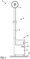
- Fig. 1 illustrates an antenna mast 2 according to embodiments.
- the antenna mast 2 comprises a mast body 4 comprising a lower module 6 and an upper module 8.
- the lower module 6 is attached to the ground 10 and supports the mast body 4 and the antenna mast 2 in its upright position.
- the lower module 6 and the upper module 8 have been assembled to form the mast body 4.
- the lower module 6 and the upper module 8 have been selected from a set of modules comprising different lower modules and different upper modules.
- the antenna mast 2 forms part of a wireless communication system.
- the upper module supports an antenna arrangement of the wireless communication system.
- the mast body 4 may house a transceiver arrangement and a processor of the wireless communication system.
- the transceiver arrangement may comprise a separate transmitter and a separate receiver, or a combined transceiver.
- the transceiver arrangement and the processor may be comprised in one unit.
- the antenna arrangement, the transceiver arrangement and the processor are involved in communication between random users of the wireless communication system, such as two persons communicating via mobile telephone or a wireless device which via a web browser accesses a website stored on a server.
- the lower module 6 carries the weight of the upper module 8, and the antenna arrangement as well as any transceiver arrangement and processor in the mast body 4.
- the upper module 8 comprises a device to be utilized for a further function, i.e. a function other than supporting the antenna arrangement.
- the device to be utilized for the further function of the upper module is a sign 12.
- the sign 12 indicates a vehicle parking facility.
- the antenna arrangement supported by the antenna mast is arranged inside the sign 12.
- the lower module 6 comprises devices to be utilized for further functions.
- a first device comprises an electronic screen 14 on which information may be presented.
- the screen 14 may be a touch screen such that a user may provide input to the first device.
- a second device comprises a card-reading device 16.
- the card-reading device 16 may for instance read plastic cards provided with a magnetic strip and/or a readable chip, such as a credit card.
- a third device to be utilized for a further function is a parking meter 18 comprising the electronic screen 14 and the card-reading device 16.
- a vehicle owner who desires to park his vehicle in the parking facility indicated by the sign 12 may thus receive information about the parking fee via the screen 14 and via the touch screen input the duration for parking the vehicle.
- the user may insert a credit card in the card-reading device 16 to pay for parking the vehicle.
- a receipt may be printed by a non-shown printer.
- the printer may form a fourth device to be utilized for a further function of the lower module 6.
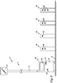
- Fig. 2 illustrates an antenna mast 2 according to embodiments.
- the antenna mast 2 comprises a mast body 4 comprising a lower module 6 and an upper module 8. Again, the lower module 6 is attached to the ground 10 and supports the mast body 4 and the antenna mast 2 in its upright position.
- the mast body 4 has been assembled from the lower module 6 and the upper module 8, which have been selected from a set of modules comprising different lower modules and different upper modules.
- the antenna mast 2 forms part of a wireless communication system and at an upper end of the antenna mast 2, the upper module 8 supports an antenna arrangement of the wireless communication system.
- the mast body 4 may house a transceiver arrangement and a processor of the wireless communication system.
- the upper module 8 comprises a device to be utilized for a further function in the form of a sign 12 and the lower module 6 comprises several devices to be utilized for further functions.
- the antenna mast 2 comprises an arrangement 20 for charging an electric vehicle.
- the sign 12 indicates such an arrangement.
- the lower module 6 thus comprises a device to be utilized for a further function in the form of an arrangement 20 for charging an electric vehicle.
- the arrangement 20 comprises three devices to be utilized for a further function; a first device comprising an electronic screen 14, a second device comprising a card-reading device 16, and a third device comprising an electric power socket 22.
- the electronic screen 14 and the card-reading device 16 may function as mentioned above in connection with the parking meter.
- the electric power socket 22 is provided for an owner of an electric vehicle to charge the electric vehicle.
- a number of separate charging posts 24, each comprising one or more electric power sockets 22, may be connected to the arrangement 20 for charging an electronic vehicle. A user desiring to charge a vehicle may thus be directed by instructions on the screen 14 to an available power socket 22 on one of the posts 24 for charging the vehicle.
- the lower modules 6 and the upper modules 8 illustrated in Figs. 1 and 2 form part of a set of modules. Accordingly, the set of modules comprises at least two different lower modules 6 and at least two different upper modules 8.
- the set of modules may comprise further lower modules 6 and/or upper modules 8 of the same kind as illustrated in Figs. 1 and 2 and/or of a different kind than illustrated in Figs. 1 and 2 .
- An antenna mast system may comprise the set of modules.
- differently configured mast bodies 4 may be assembled from the set of modules.
- a method of providing an antenna mast 2 may thus comprise selecting a lower module 6 and an upper module 8 from a set of modules, and assembling a mast body 4 including the selected lower module 6 and the selected upper module 8 to form an assembled mast body 4.
- Fig. 3 illustrates an antenna mast 2 according to embodiments.
- the antenna mast 2 comprises a mast body 4 comprising a lower module 6, a middle module 30, and an upper module 8.
- the lower module 6 is attached to the ground and supports the mast body 4 and the antenna mast 2 in its upright position.
- the mast body 4 has been assembled from the lower module 6, the middle module 30, and the upper module 8, which have been selected from a set of modules comprising different lower modules, different middle modules, and different upper modules.
- the antenna mast 2 forms part of a wireless communication system and at an upper end of the antenna mast 2, the upper module 8 supports an antenna arrangement of the wireless communication system.
- the mast body 4 may house a transceiver arrangement and a processor of the wireless communication system.
- the antenna mast 2 is adapted to be placed at an antenna site where members of the public may want to sit down or may want to know the time of day, such as at a public transportation station or at a shopping centre.
- the upper module comprises a device to be utilized for a further function other than supporting the antenna arrangement in the form of a clock 32.
- the lower module 6 thus comprises a device to be utilized for a further function in the form of a bench 34.
- the middle module 30 in these embodiments forms an extension for positioning the clock 32 and the antenna arrangement of the upper module 8 at a suitable height, such as at 3 - 8 metres above the ground.
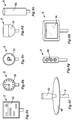
- Figs. 4a - 4i illustrate embodiments of lower modules 6 of antenna masts.
- the lower modules 6 illustrated in Figs. 4a - 4e, and 4g - 4i each comprise at least one device to be utilized for a further function, i.e. a function other than supporting an antenna arrangement of a relevant antenna mast.
- Fig. 4a illustrates a lower module 6 comprising a device to be utilized for a further function in the form of a vending machine 40.
- Fig. 4b illustrates a lower module 6 comprising a device to be utilized for a further function in the form of a parking meter 18.
- Fig. 4c illustrates a lower module 6 comprising a device to be utilized for a further function in the form of an electronic screen 14.
- Fig. 4a - 4i illustrate embodiments of lower modules 6 of antenna masts.
- the lower modules 6 illustrated in Figs. 4a - 4e, and 4g - 4i each comprise at least one device to be utilized for
- FIG. 4d illustrates a lower module 6 comprising a device to be utilized for a further function in the form of an electronic screen 14.
- the electronic screens illustrated in Figs. 4c and 4d are of different sizes. The larger screen 14 of Fig. 4d may be suited for public announcements or commercial messages whereas the smaller screen of Fig. 4c may be utilized for providing information to one person.
- Fig. 4e illustrates a lower module 6 comprising a device to be utilized for a further function in the form of a waste bin 42.
- Fig. 4f illustrates a lower module 6 without any device to be utilized for a further function. However, inside this lower module 6 there may be arranged parts of the wireless communication system.
- FIG. 4g illustrates a lower module 6 comprising a device to be utilized for a further function in the form of a traffic light 44 for a pedestrian or bicycle crossing.
- Fig. 4h illustrates a lower module 6 comprising a first device to be utilized for a further function in the form of a lighting arrangement 45, such as an electric lamp, and a second device to be utilized for a further function in the form of a roof arrangement 46.
- Fig. 4i illustrates a lower module 6 comprising a device to be utilized for a further function in the form of a defibrillator 47. At least the electrodes of the defibrillator 47 are arranged in a compartment inside the lower module 6.
- At least the electrodes of the defibrillator 47 may be taken out of the compartment for aiding a person in need.
- At least one of the devices to be utilized for a further function illustrated in each of the Figs. 4a - 4e, and 4g - 4i is housed substantially within the lower modules 6 and thus within an outer surface of the lower module 6. Portions of the devices which need to be accessible or visible in use are arranged at an outer surface of the lower module 6.
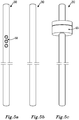
- Figs 5a - 5e illustrate embodiments of middle modules 30 of antenna masts.
- the middle modules 30 illustrated in Figs. 5a , and 5c - 5e each comprise at least one device to be utilized for a further function, i.e. a function other than supporting an antenna arrangement of a relevant antenna mast.
- Fig. 5a illustrates of a middle module 30 comprising a device to be utilized for a further function in the form of a traffic light 50.
- Fig. 5b illustrates a middle module 30 without any device to be utilized for a further function. Inside this middle module 30 there may be arranged parts of the wireless communication system.
- FIG. 5c illustrates embodiments of a middle module 30 comprising a device to be utilized for a further function in the form of a lighting arrangement 45.
- Fig. 5d illustrates embodiments of a middle module 30 comprising a device to be utilized for a further function in the form of a roof arrangement 46.
- Fig. 5e illustrates embodiments of a middle module 30 comprising a device to be utilized for a further function in the form of an electronic screen 14.
- the devices to be utilized for a further function illustrated in Figs. 5a, 5c , and 5e are housed substantially within the middle modules 30 and thus within an outer surface of the middle modules 30. Portions of the devices which need to be accessible or visible in use are arranged at an outer surface of the middle modules 30.
- Figs. 6a - 6h illustrate embodiments of upper modules 8 of antenna masts.
- the upper modules 8 illustrated in Figs. 6a - 6h support an antenna arrangement of a wireless communication system.
- Figs. 6a - 6d, and 6f - 6h each comprise at least one device to be utilized for a further function, i.e. a function other than supporting an antenna arrangement of a relevant antenna mast.
- Fig. 6a illustrates an upper module 8 comprising a device to be utilized for a further function in the form of a sign 12 for a public buss service.
- Fig. 6b illustrates an upper module 8 comprising a device to be utilized for a further function in the form of a clock 32.
- FIG. 6c illustrates an upper module 8 comprising a device to be utilized for a further function in the form of a parking sign 12.
- Fig. 6d illustrates an upper module 8 comprising a device to be utilized for a further function in the form of a lighting arrangement 45, such as an electric streetlamp.
- Fig. 6e illustrates an upper module 8 without any device to be utilized for a further function.
- Fig. 6f illustrates an upper module 8 comprising a device to be utilized for a further function in the form of a roof arrangement 46.
- Fig. 6g illustrates an upper module 8 comprising a device to be utilized for a further function in the form of a traffic light 50.
- Fig. 6h illustrates an upper module 8 comprising a device to be utilized for a further function in the form of an electronic screen 14.
- the antenna arrangement is arranged inside each of the upper modules 8 illustrated in Figs. 6a - 6h . At least a portion of an outer surface of the upper modules 8 is permeable to radio waves. Further parts of the wireless communication system may also be arranged in any of the upper modules 8 illustrated in Figs. 6a - 6h .
- the devices to be utilized for a further function illustrated in Figs. 6b, 6d, 6g, and 6h are housed substantially within the upper modules 8 and thus within an outer surface of the upper modules 8. Portions of the devices which need to be accessible or visible in use are arranged at an outer surface of the upper modules 8.
- the set of modules comprises at least two different lower modules 6, and/or at least two different middle modules 30, and/or at least two different upper modules 8.
- the set of modules may comprise all of, or a certain number of, the modules illustrated in Figs.
- An antenna mast system may comprise the set of modules.
- differently configured mast bodies 4 may be assembled from the set of modules.
- a method of providing an antenna mast 2 may thus comprise selecting a lower module 6, a middle module 30, and an upper module 8 from the set of modules, and assembling a mast body 4 including the selected lower module 6, the selected middle module 30, and the selected upper module 8 to form an assembled mast body.
- An assemble mast body may look like the mast body 4 illustrated in Fig. 3 when the set of modules also comprises a lower module 6 comprising a device to be utilized for a further function in the form of a bench 34.
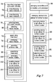
- Fig. 7 is a flow chart illustrating embodiments of a method of providing an antenna mast for a wireless communication system.
- the antenna mast 2 may be of the kind illustrated in Figs. 1 - 3 and may comprise modules 6, 8, 30 as illustrated in Figs. 4a - 4i , 5a - 5e , and 6a - 6h .
- the antenna mast comprises a mast body adapted to form a supporting structure for an antenna arrangement of the wireless communication system.
- the mast body comprises a lower module and an upper module.
- the upper module is adapted to comprise the antenna arrangement. At least one of the lower module and the upper module is adapted to comprise a device to be utilized for a further function other than supporting the antenna arrangement.
- the method comprises:
- Assembling may comprise:
- the method may comprise:
- the method may comprise:
- the method may comprise:
- the method may comprise:
- the method may comprise:
- the method may comprise:
- the method may comprise:
- the method may comprise:
- the method may comprise:
- the method may comprise:
- the method may comprise:
- An antenna mast may comprise more than three modules.
- One or more further modules may be placed on top of the upper module of a mast body of an antenna mast.
- the different modules of a mast body may be assembled in such a manner or using such method that they may be separated again, alternatively one or more of the different modules may be permanently attached to each other such that only mechanical damage will separate the modules.
- the modules may be provided with connecting elements, such as flanges or sleeves, to allow easy fitting and attachment of the lower module with a middle module or an upper module, and a middle module with an upper module.
- One or more antennas may be arranged such that they are visible from an outside of the antenna mast.
- a further device to be utilized for a further function may comprise a monitoring arrangement for instance comprising a surveillance camera.
- An antenna mast may have a height of 3-8 metres.
- Antenna masts may also have a higher height such as up to 15 metres.
- the common abbreviation " e.g .” which derives from the Latin phrase “exempli gratia,” may be used to introduce or specify a general example or examples of a previously mentioned item, and is not intended to be limiting of such item. If used herein, the common abbreviation “ i.e .”, which derives from the Latin phrase “id est,” may be used to specify a particular item from a more general recitation.
Landscapes
- Support Of Aerials (AREA)
Description
- The technical field concerned relates to a method of providing an antenna mast for a wireless communication system and a modular antenna mast system for providing antenna masts of a wireless communication system.
- Wireless communication systems using radio communication comprise transceiver arrangements and processors comprised in what may be referred to as base stations, radio network controllers, or node B:s. Furthermore, antennas are connected to the transceiver arrangements and are required for transmitting and receiving radio signals. The antennas may for instance be arranged on an antenna mast. A variety of masts have been suggested in the prior art but in practice a steel lattice mast is the most common type of mast used.
- Wireless communication such as mobile internet access by means of mobile communication equipment is demanded by more people and more devices. Thus, radio traffic within the wireless communication systems increases and so does the required number of access points for the mobile communication equipment. For each access point at least one antenna is required and thus the number of antennas that are required increases with the increased demand in mobile internet access.
-
EP1198024 discloses an antenna mast wherein an antenna is raised and lowered along a guiding means inside the antenna mast. According to one embodiment, the antenna mast comprises a carrying pipe for a lamp. -
US6335709 discloses a service tower integrating a water tank and an antenna mast in a single structure. -
EP1286412 discloses a radio tower with a central supporting tower structure comprising several modules of the same outer shape being arranged one above the other. The modules house for instance transmission and power supply equipment. Further the tower comprises stiff ring-shaped portions of covering made from glass fibre reinforced plastic material, inside which the modules of the radio tower are arranged. Each ringshaped covering is supported by a module of the radio tower. On the outside of the covering, screens for providing information or announcements may be arranged. Also the use of the covering for housing small shops or ticket machines Is suggested. -
WO98/58420 -
WO 02/073736 -
WO 02/50943 -
WO 2007/108731 discloses a hollow antenna tower structure for use in a wireless communications network. The tower comprises tubular tower sections made of concrete, and having a generally hollowed cross section. A movable base station unit, having at least one antenna and at least one micro wave link, is being disposed Inside the tubular tower. The whole base station unit Is movable up and down inside the tower by the aid of an elevator system. The tower further comprises at least one entrance into the tower and a climbing facility and/or a second elevator system, inside the tower, giving access to the base station unit. -
WO 2006/081679 discloses a method of modular pole construction and an elongate modular pole structure. A first step of the method involves providing hollow tapered pole section modules, each module having a first open end and an opposed second open end. A cross-section of the second end Is less than a cross-section of the first end. The modules are stacked to form an elongated modular pole structure of a selected length by mating the second end of a first module with the first end of a second module. The first and second modules may have different structural properties, such that poles having desired structural properties can be constructed by selectively combining modules having differing structural properties. -
WO 2007/136241 discloses a portable mobile communication tower use for wireless communication applications comprising: a) A portable cage having side panels and supporting frames assembled thereof forming an enclosed base structure for the tower, wherein the structure is provided with adjustable stabilizer stands and supporting legs for leveling and supporting the cage on uneven surface respectively. b) A mast or lattice tower constructed in modular form and having an identical but In different predetermined size of sectional mast permitting the sectional mast to be assembled section-by-section by eid of a removable winch assembly. c) A bracing member for supporting the mast or lattice tower and serve as a supporting means to restrict sway movement of the sectional mast during assembling process. The portable mobile communication tower can be easily transported and rapidly assembled in place of use; and is able to dismantled and removed from the place in a simple, quick and safe mode so that can be readily transportable elsewhere or to be stored. - A high number of access points, and accordingly antennas, for wireless communication systems puts a requirement on associated antenna masts to be accepted by the public. Providing a further function other than supporting an antenna arrangement in connection with an antenna mast, as disclosed in the above-mentioned prior art documents, may facilitate such acceptance.
- For instance in situations when a number of antenna masts are required in a restricted area, there exists a need to provide different further functions in the number of antenna masts to maintain the public acceptance. However, providing such a number of different further functions in connection with a number of antenna masts may prove to be a problem. The manufacturing and installation of such a number antenna masts may be complicated and costly.
- An object is thus to at least alleviate the above mentioned problem.
- According to an aspect, the object Is achieved by a method of providing an antenna mast for a wireless communication system. The antenna mast comprising a mast body adapted to form a supporting structure for an antenna arrangement of the wireless communication system. The mast body comprises a lower module and an upper module. The upper module Is adapted to comprise the antenna arrangement. At least one of the lower module and the upper module is adapted to comprise a device to be utilized for a further function other than supporting the antenna arrangement. The method comprises:
- selecting a lower module and an upper module from a set of modules comprising at least two different lower modules and/or at least two different upper modules, and
- assembling the mast body including the selected lower module and the selected upper module to form an assembled mast body.
- Since the antenna mast provided according to the method, assembled including the selected lower module and upper module, may be designed for a specific further function, which may be different than a further function provided in a different antenna mast assembled from the same set of modules, high flexibility in the adaptation of antenna masts is provided. As a result, the above mentioned object is achieved.
- The use of a set of modules comprising different lower modules and/or different upper modules may be a rational and advantageous way of manufacturing different antenna masts adapted to specific requirements at different antenna mast sites. For example, if the antenna mast site is an intersection between two streets, the device to be utilized for the further function may be a traffic light or a street sign. Accordingly, a lower module forming a base of the mast body may be selected from the set of modules and an upper module adapted to receive the lights of a traffic light, or adapted to form the street sign, may be selected from the set of modules. At a different example antenna mast site there may be a bus stop, in which case a lower module comprising a bench may be selected from the set of modules and an upper module adapted to support the antenna arrangement may be selected from the set of modules. A further example antenna mast site may be situated in a park area, in which case a lower module selected from the set of modules may comprise a waste bin and the upper module selected from the set of modules may be adapted to comprise a street light. Since different mast bodies may be provided, the antenna masts at different sites assembled from the set of modules may blend in well in a present environment. Public acceptance of antenna masts will thus be achieved in a rational manner.
- The upper module being adapted to comprise the antenna arrangement encompasses that the antenna arrangement may be mounted to the upper module or arranged inside the upper module. The antenna arrangement is arranged at an elevated position on the antenna mast. Accordingly, the antenna arrangement may be provided at a top of the upper module, or it is alternatively foreseen that some portions of the upper module may be provided above the antenna arrangement. It is to be understood that the set of modules comprises at least one lower and one upper module, and at least one further of the lower and upper modules.
- Different technologies may be used in wireless communication systems, such as Long Term Evolution (LTE), LTE-Advanced, 3rd Generation Partnership Project (3GPP) Wideband Code Division Multiple Access (WCDMA), Global System for Mobile Communications/Enhanced Data rate for GSM Evolution (GSM/EDGE), Worldwide Interoperability for Microwave Access (WiMax), or Ultra Mobile Broadband (UMB), just to mention a few possible implementations. A wireless communication system may comprise transceiver arrangements and processors providing radio coverage over at least one respective geographical area forming a cell. User equipment, such as mobile telephones, are served in the cells by the respective transceiver arrangements and processors and communicate with the respective transceiver arrangements and processors. An antenna mast may be erected at an antenna site in a cell. Typically, such antenna sites are outdoors in areas frequented by the public. In such areas, use of wireless communication systems is to be expected.
- According to embodiments the further function may be a function other than a function directly related to the wireless communication system. It is to be understood that the device to be utilized for the further function of a specific assembled antenna mast may make use of the wireless communication system but the device is not involved in communication between random users of the wireless communication system utilizing the antenna arrangement of the specific assembled antenna mast. Put differently, the communication between the random users of the wireless communication system is performed independently of any communication relating to the device to be utilized for the further function. A device to be utilized for a further function may communicate e.g. its status of operation to a service provider via the wireless communication system.
- According to embodiments assembling may comprise:
- arranging the lower module substantially below the upper module in the assembled mast body.
- According to embodiments the method may comprise:
- manufacturing the lower modules, and the upper modules of the set of modules to form at least part of an outer surface of the assembled mast body. In this manner a mast body assembled from the set of modules may comprise a continuous outer surface.
- According to embodiments the method may comprise:
- manufacturing lower modules to form a supporting structure which is adapted to carry at least a weight of an upper module and devices arranged in the upper module of an assembled mast body. In this manner a lower module may carry the weight of an assembled mast body and be fastened to the ground to support the relevant antenna mast.
- According to embodiments the method may comprise:
- arranging the device to be utilized for the further function substantially within the outer surface of the assembled mast body. In this manner the device to be utilized for the further function may blend in well with the mast body to form a homogeneous antenna mast. The device to be utilized for the further function may be protectedly arranged in the antenna mast body.
- According to embodiments the method may comprise:
- providing an antenna mast having a height of 3 - 8 metres.
- According to embodiments the method may comprise:
- arranging a particular device to be utilized for the further function in the assembled mast body in dependence of the selected modules from the set of modules. The arranging of a particular device to be utilized for the further function in the mast body may thus depend on which specific module is selected from the set of modules. The device may be arranged in a module before the mast body is assembled or after the mast body has been assembled.
- According to embodiments the method may comprise:
- arranging at least a transmitter, and/or a receiver, and a processor of the wireless communication system inside the selected lower and/or upper modules. In this manner the antenna mast may house these components of the wireless communication system. The arranging of the transmitter, and/or the receiver, and the processor inside the lower and/or upper modules may be done before the mast body is assembled or after the mast body has been assembled.
- According to embodiments the method may comprise:
- providing the device to be utilized for the further function in connection with the lower module of the assembled mast body.
- According to embodiments the method may comprise:
- selecting the device to be utilized for the further function from the group of: a bench, a roof arrangement, a waste bin, a vending machine, an electronic screen, a parking meter, a traffic light, a lighting arrangement, a card-reading device, an electric power socket, or a life-saving device such as a defibrillator. Different functions, services, and devices may thus be provided. A bench may be provided at antenna mast sites where members of the public may want to sit down. A roof arrangement may be provided at antenna mast sites where members of the public may need shelter from precipitation or the sun. A waste bin may be provided at an antenna mast site which is frequented by many people. A vending machine may be provided at an antenna mast site which is frequented by many people. An electronic screen may be provided at an antenna mast site where there is a need or requirement to provide information to one or more persons. A parking meter may be provided at an antenna mast site in vicinity of a vehicle parking facility. One or more traffic lights may be provided at an antenna mast site at a roadside, in a street intersection, or at a crossing for pedestrians. A card-reading device may be provided e.g. at an antenna mast sites where a service provider may want to charge for services provided, e.g. at a vehicle parking facility, an electric vehicle charging arrangement, a public transportation station, etc. An electric power socket may be provided at an antenna mast site where electric vehicles may be charged. A life-saving device, such as a defibrillator, or an oxygen container and mask, may be provided at an antenna mast site which is frequented by many people or a site where there may be a particular reason to provide such equipment.
- According to embodiments the method may comprise:
- providing the device to be utilized for performing the further function besides the antenna arrangement in connection with the upper module of the assembled mast body.
- According to embodiments the method may comprise:
- s electing the device to be utilized for the further function from a group of: a sign, a lighting arrangement, a clock, a roof arrangement, a traffic light, or an electronic screen. Different functions, services, and devices may thus be provided. A sign may be provided at an antenna mast site where information is to be displayed to members of the public. A lighting arrangement such as one or more lamps may be provided at an antenna mast site frequented by members of the public at dark hours. A clock may be provided at an antenna mast site near a public transportation station. A roof arrangement may be provided at an antenna mast site where members of the public may need shelter from precipitation or the sun. One or more traffic lights may be provided at an antenna mast site at a roadside, in a street intersection, or at a crossing for pedestrians. An electronic screen may be provided at an antenna mast site where there is a need or requirement to provide information to one or more persons.
- According to embodiments the set of modules may comprise at least two different lower modules and/or at least two different middle modules and/or at least two different upper modules, and wherein selecting may comprise:
- selecting a middle module from the set of modules, and assembling may comprise:
- assembling the mast body including the selected middle module to form the assembled mast body. In this manner antenna masts comprising a middle module besides upper and lower modules may be provided. The middle modules being comprised in the set of modules ensures flexibility to provide an antenna mast adapted for a specific antenna mast site. More and/or different combinations of modules are provided.
- According to embodiments, assembling the antenna mast body may comprise:
- arranging the middle module substantially between the lower module and the upper module.
- According to embodiments the method may comprise:
- providing the device to be utilized for the further function in connection with the middle module.
- According to embodiments the method may comprise:
- selecting the device to be utilized for the further function from a group of: a traffic light, an electronic screen, a roof arrangement, or a lighting arrangement. Different functions, services, and devices may thus be provided. One or more traffic lights may be provided at an antenna mast site at a roadside, in a street intersection, or at a crossing for pedestrians. An electronic screen may be provided at an antenna mast site where there is a need or requirement to provide information to one or more persons. A roof arrangement may be provided at an antenna mast site where members of the public may need shelter from precipitation or the sun. A lighting arrangement such as one or more lamps may be provided at an antenna mast site frequented by members of the public at dark hours.
- According to embodiments a lower module of the set of modules may form a supporting structure which is adapted to carry a weight of a middle module, an upper module, and devices arranged in the middle and upper modules. In this manner a lower module may carry the weight of an assembled mast body and be fastened to the ground to support the relevant antenna mast.
- According to a further aspect, the object is achieved by a modular antenna mast system for providing antenna masts of a wireless communication system, at least some of the antenna masts of the antenna mast system each comprising a mast body adapted to form a supporting structure for an antenna arrangement of the wireless communication system. The mast body comprises a lower module and an upper module, the upper module being adapted to comprise the antenna arrangement. At least one of the lower module and the upper module is adapted to comprise a device to be utilized for a further function other than supporting the antenna arrangement. The antenna mast system comprises a set of modules comprising lower and upper modules, wherein the set of modules comprises at least two different lower modules and/or at least two different upper modules such that differently configured mast bodies comprising a lower and an upper module are able to be assembled from the set of modules.
- Since the antenna mast system comprises a set of modules from which differently configured mast bodies are assembled, an antenna mast may be designed for a specific further function, which may be different than a further function provided in a different antenna mast assembled from the same set of modules. Again, high flexibility in the adaptation of antenna masts to a particular antenna site is provided. As a result, the above mentioned object is achieved.
- According to embodiments the further function may be a function other than a function directly related to the wireless communication system. It is to be understood that the device to be for the further function of a specific assembled antenna mast may make use of the wireless communication system but the device is not involved in communication between random users of the wireless communication system utilizing the antenna arrangement of the specific assembled antenna mast. For instance, a device to be utilized for a further function may communicate its status of operation to a service provider via the wireless communication system.
- According to embodiments a lower module may be arranged substantially below an upper module in an assembled mast body of an antenna mast of the antenna mast system.
- According to embodiments a lower module and an upper module may form at least part of an outer surface of an assembled mast body of an antenna mast of the antenna mast system. In this manner a mast body assembled from the set of modules may comprise a continuous outer surface.
- According to embodiments a lower module of the set of modules may form a supporting structure which is adapted to carry at least a weight of an upper module and devices arranged in the upper module of an assembled mast body. In this manner a lower module may carry the weight of an assembled mast body and be fastened to the ground to support the relevant antenna mast.
- According to embodiments an assembled mast body of an antenna mast of the antenna mast system may be adapted to house the device to be utilized for the further function substantially within the outer surface of the assembled mast body. In this manner the device to be utilized for the further function may blend in well with the mast body to form a homogeneous antenna mast. The device to be utilized for the further function may be protectedly arranged in the antenna mast body.
- According to embodiments at least some of the antennas masts of the antenna mast system may have a height of 3 - 8 metres.
- According to embodiments the differently configured mast bodies of the modular antenna mast system may be arranged to comprise different devices to be utilized for the further function depending on which modules are selected from the set of modules for a particular mast body. The arranging of a particular device to be utilized for the further function in the mast body may thus depend on which specific module is selected from the set of modules. The device may be arranged in a module before the mast body is assembled or after the mast body has been assembled.
- According to embodiments at least one of the differently configured mast bodies may be adapted to house therein at least a transmitter and/or a receiver and a processor of the wireless communication system. In this manner an antenna mast with a mast body may be provided, which may be adapted to provide for the device for performing the further function, and which also may house key components of the wireless communication system.
- According to embodiments at least one lower module of the set of modules may be adapted to comprise the device to be utilized for the further function.
- According to embodiments the device to be utilized for the further function may comprise a bench, a roof arrangement, a waste bin, a vending machine, an electronic screen, a parking meter, a traffic light, a lighting arrangement, a card-reading device, an electric power socket, or a life-saving device such as a defibrillator.
- According to embodiments at least one upper module of the set of modules may be adapted to comprise the device to be utilized for the further function, besides the antenna arrangement.
- According to embodiments the device to be utilized for the further function may comprises: a sign, a lighting arrangement, a clock, a roof arrangement, a traffic light, or an electronic screen.
- According to embodiments the set of modules may comprise at least two different lower modules and/or at least two different middle modules and/or at least two different upper modules such that differently configured mast bodies comprising a middle module are able to be assembled from the set of modules. In this manner antenna masts comprising a middle module besides upper and lower modules may be provided. The middle modules being comprised in the set of modules ensures flexibility to provide an antenna mast adapted for a specific antenna mast site.
- According to embodiments a middle module may be arranged substantially between a lower module and an upper module of an assembled mast body of an antenna mast of the antenna mast system.
- According to embodiments at least one middle module of the set of modules may be adapted to comprise the device to be utilized for the further function.
- According to embodiments the device to be utilized for the further function may comprise: a traffic light, an electronic screen, a roof arrangement, or a lighting arrangement.
- According to embodiments a lower module forms a supporting structure which is adapted to carry a weight of a middle module, an upper module, and devices arranged in the middle and upper modules. In this manner a lower module may carry the weight of an assembled mast body and be fastened to the ground to support the relevant antenna mast.
- Further features of, and advantages, will become apparent when studying the appended claims and the following detailed description. Those skilled in the art will realize that different features of embodiments may be combined to create embodiments other than those described in the following, without departing from the scope defined by the appended claims.
- The various aspects of embodiments, including particular features and advantages, will be readily understood from the following detailed description and the accompanying drawings, in which:
-
Figs. 1 - 3 illustrate antenna masts according to embodiments, -
Figs. 4a - 4i illustrate embodiments of lower modules of antenna masts, -
Figs 5a - 5e illustrate embodiments of middle modules of antenna masts, -
Figs. 6a - 6h illustrate embodiments of upper modules of antenna masts, and -
Fig. 7 is a flow chart illustrating embodiments of a method of providing an antenna mast for a wireless communication system. - Embodiments will now be described more fully with reference to the accompanying drawings, in which example embodiments are shown. The embodiments set forth herein should not be construed as limiting. Disclosed features of example embodiments may be combined as readily understood by one of ordinary skill in the art. Like numbers refer to like elements throughout.
- Well-known functions or constructions will not necessarily be described in detail for brevity and/or clarity.
-
Fig. 1 illustrates anantenna mast 2 according to embodiments. Theantenna mast 2 comprises amast body 4 comprising alower module 6 and anupper module 8. Thelower module 6 is attached to theground 10 and supports themast body 4 and theantenna mast 2 in its upright position. Thelower module 6 and theupper module 8 have been assembled to form themast body 4. Thelower module 6 and theupper module 8 have been selected from a set of modules comprising different lower modules and different upper modules. - The
antenna mast 2 forms part of a wireless communication system. At an upper end of theantenna mast 2 the upper module supports an antenna arrangement of the wireless communication system. Themast body 4 may house a transceiver arrangement and a processor of the wireless communication system. The transceiver arrangement may comprise a separate transmitter and a separate receiver, or a combined transceiver. Also the transceiver arrangement and the processor may be comprised in one unit. The antenna arrangement, the transceiver arrangement and the processor are involved in communication between random users of the wireless communication system, such as two persons communicating via mobile telephone or a wireless device which via a web browser accesses a website stored on a server. - The
lower module 6 carries the weight of theupper module 8, and the antenna arrangement as well as any transceiver arrangement and processor in themast body 4. - The
upper module 8 comprises a device to be utilized for a further function, i.e. a function other than supporting the antenna arrangement. In these embodiments the device to be utilized for the further function of the upper module is asign 12. In these embodiments thesign 12 indicates a vehicle parking facility. The antenna arrangement supported by the antenna mast is arranged inside thesign 12. - The
lower module 6 comprises devices to be utilized for further functions. A first device comprises anelectronic screen 14 on which information may be presented. Thescreen 14 may be a touch screen such that a user may provide input to the first device. A second device comprises a card-readingdevice 16. The card-readingdevice 16 may for instance read plastic cards provided with a magnetic strip and/or a readable chip, such as a credit card. A third device to be utilized for a further function is aparking meter 18 comprising theelectronic screen 14 and the card-readingdevice 16. A vehicle owner who desires to park his vehicle in the parking facility indicated by thesign 12 may thus receive information about the parking fee via thescreen 14 and via the touch screen input the duration for parking the vehicle. The user may insert a credit card in the card-readingdevice 16 to pay for parking the vehicle. A receipt may be printed by a non-shown printer. The printer may form a fourth device to be utilized for a further function of thelower module 6. -
Fig. 2 illustrates anantenna mast 2 according to embodiments. Theantenna mast 2 comprises amast body 4 comprising alower module 6 and anupper module 8. Again, thelower module 6 is attached to theground 10 and supports themast body 4 and theantenna mast 2 in its upright position. Themast body 4 has been assembled from thelower module 6 and theupper module 8, which have been selected from a set of modules comprising different lower modules and different upper modules. - Again, the
antenna mast 2 forms part of a wireless communication system and at an upper end of theantenna mast 2, theupper module 8 supports an antenna arrangement of the wireless communication system. Themast body 4 may house a transceiver arrangement and a processor of the wireless communication system. - The
upper module 8 comprises a device to be utilized for a further function in the form of asign 12 and thelower module 6 comprises several devices to be utilized for further functions. - In these embodiments the
antenna mast 2 comprises anarrangement 20 for charging an electric vehicle. Accordingly, thesign 12 indicates such an arrangement. Thelower module 6 thus comprises a device to be utilized for a further function in the form of anarrangement 20 for charging an electric vehicle. Thearrangement 20 comprises three devices to be utilized for a further function; a first device comprising anelectronic screen 14, a second device comprising a card-readingdevice 16, and a third device comprising anelectric power socket 22. Theelectronic screen 14 and the card-readingdevice 16 may function as mentioned above in connection with the parking meter. Theelectric power socket 22 is provided for an owner of an electric vehicle to charge the electric vehicle. A number of separate charging posts 24, each comprising one or moreelectric power sockets 22, may be connected to thearrangement 20 for charging an electronic vehicle. A user desiring to charge a vehicle may thus be directed by instructions on thescreen 14 to anavailable power socket 22 on one of theposts 24 for charging the vehicle. - The
lower modules 6 and theupper modules 8 illustrated inFigs. 1 and2 form part of a set of modules. Accordingly, the set of modules comprises at least two differentlower modules 6 and at least two differentupper modules 8. The set of modules may comprise furtherlower modules 6 and/orupper modules 8 of the same kind as illustrated inFigs. 1 and2 and/or of a different kind than illustrated inFigs. 1 and2 . An antenna mast system may comprise the set of modules. Thus, differently configuredmast bodies 4 may be assembled from the set of modules. A method of providing anantenna mast 2 may thus comprise selecting alower module 6 and anupper module 8 from a set of modules, and assembling amast body 4 including the selectedlower module 6 and the selectedupper module 8 to form an assembledmast body 4. -
Fig. 3 illustrates anantenna mast 2 according to embodiments. Theantenna mast 2 comprises amast body 4 comprising alower module 6, amiddle module 30, and anupper module 8. Thelower module 6 is attached to the ground and supports themast body 4 and theantenna mast 2 in its upright position. Themast body 4 has been assembled from thelower module 6, themiddle module 30, and theupper module 8, which have been selected from a set of modules comprising different lower modules, different middle modules, and different upper modules. - Again, the
antenna mast 2 forms part of a wireless communication system and at an upper end of theantenna mast 2, theupper module 8 supports an antenna arrangement of the wireless communication system. Themast body 4 may house a transceiver arrangement and a processor of the wireless communication system. In these embodiments theantenna mast 2 is adapted to be placed at an antenna site where members of the public may want to sit down or may want to know the time of day, such as at a public transportation station or at a shopping centre. The upper module comprises a device to be utilized for a further function other than supporting the antenna arrangement in the form of aclock 32. Thelower module 6 thus comprises a device to be utilized for a further function in the form of abench 34. Themiddle module 30 in these embodiments forms an extension for positioning theclock 32 and the antenna arrangement of theupper module 8 at a suitable height, such as at 3 - 8 metres above the ground. -
Figs. 4a - 4i illustrate embodiments oflower modules 6 of antenna masts. Thelower modules 6 illustrated inFigs. 4a - 4e, and 4g - 4i each comprise at least one device to be utilized for a further function, i.e. a function other than supporting an antenna arrangement of a relevant antenna mast.Fig. 4a illustrates alower module 6 comprising a device to be utilized for a further function in the form of avending machine 40.Fig. 4b illustrates alower module 6 comprising a device to be utilized for a further function in the form of aparking meter 18.Fig. 4c illustrates alower module 6 comprising a device to be utilized for a further function in the form of anelectronic screen 14.Fig. 4d illustrates alower module 6 comprising a device to be utilized for a further function in the form of anelectronic screen 14. The electronic screens illustrated inFigs. 4c and 4d are of different sizes. Thelarger screen 14 ofFig. 4d may be suited for public announcements or commercial messages whereas the smaller screen ofFig. 4c may be utilized for providing information to one person.Fig. 4e illustrates alower module 6 comprising a device to be utilized for a further function in the form of awaste bin 42.Fig. 4f illustrates alower module 6 without any device to be utilized for a further function. However, inside thislower module 6 there may be arranged parts of the wireless communication system.Fig. 4g illustrates alower module 6 comprising a device to be utilized for a further function in the form of atraffic light 44 for a pedestrian or bicycle crossing.Fig. 4h illustrates alower module 6 comprising a first device to be utilized for a further function in the form of alighting arrangement 45, such as an electric lamp, and a second device to be utilized for a further function in the form of aroof arrangement 46.Fig. 4i illustrates alower module 6 comprising a device to be utilized for a further function in the form of adefibrillator 47. At least the electrodes of thedefibrillator 47 are arranged in a compartment inside thelower module 6. By opening adoor 48 of the compartment at least the electrodes of thedefibrillator 47 may be taken out of the compartment for aiding a person in need. At least one of the devices to be utilized for a further function illustrated in each of theFigs. 4a - 4e, and 4g - 4i is housed substantially within thelower modules 6 and thus within an outer surface of thelower module 6. Portions of the devices which need to be accessible or visible in use are arranged at an outer surface of thelower module 6. -
Figs 5a - 5e illustrate embodiments ofmiddle modules 30 of antenna masts. Themiddle modules 30 illustrated inFigs. 5a , and5c - 5e each comprise at least one device to be utilized for a further function, i.e. a function other than supporting an antenna arrangement of a relevant antenna mast.Fig. 5a illustrates of amiddle module 30 comprising a device to be utilized for a further function in the form of atraffic light 50.Fig. 5b illustrates amiddle module 30 without any device to be utilized for a further function. Inside thismiddle module 30 there may be arranged parts of the wireless communication system.Fig. 5c illustrates embodiments of amiddle module 30 comprising a device to be utilized for a further function in the form of alighting arrangement 45.Fig. 5d illustrates embodiments of amiddle module 30 comprising a device to be utilized for a further function in the form of aroof arrangement 46.Fig. 5e illustrates embodiments of amiddle module 30 comprising a device to be utilized for a further function in the form of anelectronic screen 14. The devices to be utilized for a further function illustrated inFigs. 5a, 5c , and5e are housed substantially within themiddle modules 30 and thus within an outer surface of themiddle modules 30. Portions of the devices which need to be accessible or visible in use are arranged at an outer surface of themiddle modules 30. -
Figs. 6a - 6h illustrate embodiments ofupper modules 8 of antenna masts. Theupper modules 8 illustrated inFigs. 6a - 6h support an antenna arrangement of a wireless communication system.Figs. 6a - 6d, and 6f - 6h each comprise at least one device to be utilized for a further function, i.e. a function other than supporting an antenna arrangement of a relevant antenna mast.Fig. 6a illustrates anupper module 8 comprising a device to be utilized for a further function in the form of asign 12 for a public buss service.Fig. 6b illustrates anupper module 8 comprising a device to be utilized for a further function in the form of aclock 32.Fig. 6c illustrates anupper module 8 comprising a device to be utilized for a further function in the form of aparking sign 12.Fig. 6d illustrates anupper module 8 comprising a device to be utilized for a further function in the form of alighting arrangement 45, such as an electric streetlamp.Fig. 6e illustrates anupper module 8 without any device to be utilized for a further function. Inside ashell 62 permeable to radio waves the antenna arrangement of a wireless communication system is arranged.Fig. 6f illustrates anupper module 8 comprising a device to be utilized for a further function in the form of aroof arrangement 46. Inside ashell 62 permeable to radio waves the antenna arrangement of a wireless communication system is arranged.Fig. 6g illustrates anupper module 8 comprising a device to be utilized for a further function in the form of atraffic light 50.Fig. 6h illustrates anupper module 8 comprising a device to be utilized for a further function in the form of anelectronic screen 14. - The antenna arrangement is arranged inside each of the
upper modules 8 illustrated inFigs. 6a - 6h . At least a portion of an outer surface of theupper modules 8 is permeable to radio waves. Further parts of the wireless communication system may also be arranged in any of theupper modules 8 illustrated inFigs. 6a - 6h . The devices to be utilized for a further function illustrated inFigs. 6b, 6d, 6g, and 6h are housed substantially within theupper modules 8 and thus within an outer surface of theupper modules 8. Portions of the devices which need to be accessible or visible in use are arranged at an outer surface of theupper modules 8. - At least one of the
lower modules 6 ofFigs. 4a - 4i , at least one of themiddle modules 30 ofFigs. 5a - 5e , and at least one of theupper modules 8 ofFigs. 6a - 6h together with at least one further of thelower modules 6 ofFigs. 4a - 4i , or themiddle modules 30 ofFigs. 5a - 5e , or theupper modules 8 ofFigs. 6a - 6h form a set of modules. Accordingly, the set of modules comprises at least two differentlower modules 6, and/or at least two differentmiddle modules 30, and/or at least two differentupper modules 8. The set of modules may comprise all of, or a certain number of, the modules illustrated inFigs. 4a - 4i ,5a - 5e , and6a - 6h . An antenna mast system may comprise the set of modules. Thus, differently configuredmast bodies 4 may be assembled from the set of modules. A method of providing anantenna mast 2 may thus comprise selecting alower module 6, amiddle module 30, and anupper module 8 from the set of modules, and assembling amast body 4 including the selectedlower module 6, the selectedmiddle module 30, and the selectedupper module 8 to form an assembled mast body. An assemble mast body may look like themast body 4 illustrated inFig. 3 when the set of modules also comprises alower module 6 comprising a device to be utilized for a further function in the form of abench 34. -
Fig. 7 is a flow chart illustrating embodiments of a method of providing an antenna mast for a wireless communication system. Theantenna mast 2 may be of the kind illustrated inFigs. 1 - 3 and may comprisemodules Figs. 4a - 4i ,5a - 5e , and6a - 6h . The antenna mast comprises a mast body adapted to form a supporting structure for an antenna arrangement of the wireless communication system. The mast body comprises a lower module and an upper module. The upper module is adapted to comprise the antenna arrangement. At least one of the lower module and the upper module is adapted to comprise a device to be utilized for a further function other than supporting the antenna arrangement. The method comprises: - Selecting 70 a lower module and an upper module from a set of modules comprising at least two different lower modules and/or at least two different upper modules.
- Assembling 72 the mast body including the selected lower module and the selected upper module to form an assembled mast body. The further function may be a function other than a function directly related to the wireless communication system.
- Assembling may comprise:
- Arranging 74 the lower module substantially below the upper module in the assembled mast body.
- The method may comprise:
-
Manufacturing 76 the lower modules, and the upper modules of the set of modules to form at least part of an outer surface of the assembled mast body. - The method may comprise:
-
Manufacturing 78 lower modules to form a supporting structure which is adapted to carry at least a weight of an upper module and devices arranged in the upper module of an assembled mast body. - The method may comprise:
- Arranging 80 the device to be utilized for the further function substantially within the outer surface of the assembled mast body.
- The method may comprise:
- Providing 82 an antenna mast having a height of 3 - 8 metres.
- The method may comprise:
- Arranging 84 a particular device to be utilized for the further function in the assembled mast body in dependence of the selected modules from the set of modules.
- The method may comprise:
- Arranging 86 at least a transmitter, and/or a receiver, and a processor of the wireless communication system inside the selected lower and/or upper modules.
- The method may comprise:
- Providing 88 the device to be utilized for the further function in connection with the lower module of the assembled mast body.
- The method may comprise:
- Selecting 90 the device to be utilized for the further function from the group of: a bench, a roof arrangement, a waste bin, a vending machine, an electronic screen, a parking meter, a traffic light, a lighting arrangement, a card-reading device, an electric power socket, or a life-saving device such as a defibrillator.
- The method may comprise:
- Providing 92 the device to be utilized for performing the further function besides the antenna arrangement in connection with the upper module of the assembled mast body.
- The method may comprise:
- Selecting 94 the device to be utilized for the further function from a group of: a sign, a lighting arrangement, a clock, a roof arrangement, a traffic light, or an electronic screen.
- If the set of modules comprises at least two different middle modules the method may comprise:
- Selecting 96 a middle module from the set of modules, and assembling 72 comprises:
- Assembling 98 the mast body including the selected middle module to form the assembled mast body. Assembling 98 the antenna mast body may comprise:
- Arranging 100 the middle module substantially between the lower module and the upper module. The method may comprise:
- Providing 102 the device to be utilized for the further function in connection with the middle module. The method may comprise:
- Selecting 104 the device to be utilized for the further function in the middle module from a group of: a traffic light, an electronic screen, a roof arrangement, or a lighting arrangement. The method may comprise:
- Manufacturing 106 the lower modules of the set of modules to form a supporting structure which is adapted to carry a weight of a middle module, an upper module, and devices arranged in the middle and upper modules.
- Example embodiments described above may be combined as understood by a person skilled in the art. It is also understood by those skilled in the art that steps of the method illustrated in
Fig. 7 may be performed in a different order than illustrated inFig. 7 . An antenna mast may comprise more than three modules. One or more further modules may be placed on top of the upper module of a mast body of an antenna mast. The different modules of a mast body may be assembled in such a manner or using such method that they may be separated again, alternatively one or more of the different modules may be permanently attached to each other such that only mechanical damage will separate the modules. The modules may be provided with connecting elements, such as flanges or sleeves, to allow easy fitting and attachment of the lower module with a middle module or an upper module, and a middle module with an upper module. One or more antennas may be arranged such that they are visible from an outside of the antenna mast. A further device to be utilized for a further function may comprise a monitoring arrangement for instance comprising a surveillance camera. An antenna mast may have a height of 3-8 metres. Antenna masts may also have a higher height such as up to 15 metres. - Therefore, it is to be understood that the foregoing is illustrative of various example embodiments and that modifications to the disclosed embodiments, combinations of features of disclosed embodiments as well as other embodiments are intended to be included within the scope of the appended claims.
- As used herein, the term "comprising" or "comprises" is open-ended, and includes one or more stated features, elements, steps, components or functions but does not preclude the presence or addition of one or more other features, elements, steps, components, functions or groups thereof.
- As used herein, the term "and/or" includes any and all combinations of one or more of the associated listed items.
- As used herein, the common abbreviation "e.g.", which derives from the Latin phrase "exempli gratia," may be used to introduce or specify a general example or examples of a previously mentioned item, and is not intended to be limiting of such item. If used herein, the common abbreviation "i.e.", which derives from the Latin phrase "id est," may be used to specify a particular item from a more general recitation.
- The terminology used herein is for the purpose of describing particular embodiments only and is not intended to be limiting. As used herein, the singular forms "a", "an" and "the" are intended to include the plural forms as well, unless the context clearly indicates otherwise.
- Unless otherwise defined, all terms (including technical and scientific terms) used herein have the same meaning as commonly understood by one of ordinary skill in the art belongs. It will be further understood that terms, such as those defined in commonly used dictionaries, should be interpreted as having a meaning that is consistent with their meaning in the context of the relevant art and will not be interpreted in an idealized or overly formal sense unless expressly so defined herein.
- It will be understood that when an element is referred to as being "coupled" or "connected" to another element, it can be directly coupled or connected to the other element or intervening elements may also be present. In contrast, when an element is referred to as being "directly coupled" or "directly connected" to another element, there are no intervening elements present.
Claims (36)
- A method of providing an antenna mast (2) for a wireless communication system, the antenna mast comprising a mast body (4) forming a supporting structure for an antenna arrangement of the wireless communication system, wherein the mast body comprises a lower module (6) and an upper module (8), the upper module comprises the antenna arrangement, and wherein at least one of the lower module and the upper module comprises a device to be utilized for a further function other than supporting the antenna arrangement, the method comprising:- selecting (70) a lower module and an upper module from a set of modules comprising at least two different lower modules and at least two different upper modules, and- assembling (72) the mast body including the selected lower module and the selected upper module to form an assembled mast body.
- The method according to claim 1, wherein the further function is a function other than a function directly related to the wireless communication system.
- The method according to any one of the preceding claims, wherein assembling (72) comprises:- arranging (74) the lower module substantially below the upper module in the assembled mast body.
- The method according to any one of the preceding claims, wherein the method comprises:- manufacturing (78) the lower modules, and the upper modules of the set of modules to form at least part of an outer surface of the assembled mast body.
- The method according to any one of the preceding claims, wherein the method comprises:- manufacturing (78) lower modules to form a supporting structure which is adapted to carry at least a weight of an upper module and devices arranged in the upper module of an assembled mast body.
- The method according to claim 5, wherein the method comprises:- arranging (80) the device to be utilized for the further function substantially within the outer surface of the assembled mast body.
- The method according to any one of the preceding claims, wherein the method comprises:- providing (82) an antenna mast having a height of 3 - 8 metres.
- The method according to any one of the preceding claims, wherein the method comprises;- arranging (84) a particular device to be utilized for the further function in the assembled mast body in dependence of the selected modules from the set of modules.
- The method according to any one of the preceding claims, wherein the method comprises:- arranging (86) at least a transmitter, and/or a receiver, and a processor of the wireless communication system inside the selected lower and/or upper modules.
- The method according to any one of the preceding claims, wherein the method comprises:- providing (88) the device to be utilized for the further function in connection with the lower module of the assembled mast body.
- The method according to claim 10, wherein the method comprises:- selecting (90) the device to be utilized for the further function from the group of: a bench, a roof arrangement, a waste bin, a vending machine, an electronic screen, a parking meter, a traffic light, a lighting arrangement, a card-reading device, an electric power socket, or a life-saving device such as a defibrillator.
- The method according to any one of the preceding claims, wherein the method comprises:- providing (92) the device to be utilized for the further function besides the antenna arrangement in connection with the upper module of the assembled mast body.
- The method according to claim 12, wherein the method comprises:selecting (94) the device to be utilized for the further function from a group of: a sign,a lighting arrangement, a clock, a roof arrangement, a traffic light, or an electronic screen.
- The method according to any one of the preceding claims, wherein the set of modules comprises at least two different lower modules and at least two different middle modules and at least two different upper modules, and wherein selecting (70) comprises:- selecting (96) a middle module from the set of modules, and assembling (72) comprises;- assembling (98) the mast body including the selected middle module to form the assembled mast body.
- The method according to claim 14, wherein assembling the antenna mast body comprises:- arranging (100) the middle module substantially between the lower module and the upper module.
- The method according to any one of claims 14 and 15, wherein the method comprises:- providing (102) the device to be utilized for the further function in connection with the middle module.
- The method according to claim 16, wherein the method comprises:selecting (104) the device to be utilized for the further function from a group of: a traffic light, an electronic screen, a roof arrangement, or a lighting arrangement.
- The method according to any one of claims 14 - 17, wherein a lower module of the set of modules forms a supporting structure which is adapted to carry a weight of a middle module, an upper module, and devices arranged in the middle and upper modules.
- A modular antenna mast system for providing antenna masts (2) of a wireless communication system, the antenna masts (2) of the antenna mast system each comprising a mast body (4) forming a supporting structure for an antenna arrangement of the wireless communication system, wherein the mast body (4) comprises a lower module (6) and an upper module (8), the upper module (6) comprises the antenna arrangement, and wherein at least one of the lower module (6) and the upper module (8) comprises a device to be utilized for a further function other than supporting the antenna arrangement
characterized in that
the antenna mast system comprises a set of modules comprising lower and upper modules (6, 8), wherein the set of modules comprises at least two different lower modules (6) and at least two different upper modules (8) such that differently configured mast bodies (4) comprising a lower and an upper module (6, 8) are able to be assembled from the set of modules. - The modular antenna mast system according to claim 19, wherein the further function is a function other than a function directly related to the wireless communication system.
- The modular antenna mast system according to any one of the claims 19 and 20, wherein a lower module (6) is arranged substantially below an upper module (8) in an assembled mast body (4) of an antenna mast (2) of the antenna mast system.
- The modular antenna mast system according to any one of the claims 19 - 21, wherein a lower module (6) and an upper module (8) form at least part of an outer surface of an assembled mast body (4) of an antenna mast (2) of the antenna mast system.
- The modular antenna mast system according to any one of the claims 19 - 22, wherein a lower module (6) of the set of modules forms a supporting structure which is adapted to carry at least a weight of an upper module (8) and devices arranged in the upper module (8) of an assembled mast body (4).
- The modular antenna mast system according to claim 23, wherein an assembled mast body (4) of an antenna mast (2) of the antenna mast system is adapted to house the device to be utilized for the further function substantially within an outer surface of the assembled mast body (4).
- The modular antenna mast system according to any one of the claims 19 - 24, wherein the antennas masts (2) of the antenna mast system have a height of 3 - 8 metres.
- The modular antenna mast system according to any one of the claims 19 - 25, wherein the differently configured mast bodies (4) of the modular antenna mast system are arranged to comprise different devices to be utilized for the further function depending on which modules are selected from the set of modules for a particular mast body (4).
- The modular antenna mast system according to any one of the claims 19 - 26, wherein at least one of the differently configured mast bodies (4) are adapted to house therein at least a transmitter and/or receiver and a processor of the wireless communication system.
- The modular antenna mast system according to any one of the claims 19 - 27, wherein at least one lower module (6) of the set of modules is adapted to comprise the device to be utilized for the further function.
- The modular antenna mast system according to claim 28, wherein the device to be utilized for the further function comprises a bench (34), a roof arrangement (46), a waste bin (42), a vending machine (40), an electronic screen (14), a parking meter (18), a traffic light (44, 50), a lighting arrangement (45), a card-reading device (16), an electric power socket (22), or a life-saving device such as a defibrillator (47).
- The modular antenna mast system according to any one of the claims 19 - 29, wherein at least one upper module (8) of the set of modules is adapted to comprise the device to be utilized for the further function, besides the antenna arrangement.
- The modular antenna mast system according to claim 30, wherein the device to be utilized for the further function comprises: a sign (12), a lighting arrangement (45), a clock (32), a roof arrangement (46), a traffic light (44, 50), or an electronic screen (14).
- The modular antenna mast system according to any one of claims 19 - 30, wherein the set of modules comprises at least two different lower modules (6) and at least two different middle modules (30) and at least two different upper modules (6) such that differently configured mast bodies (4) comprising a middle module (30) are able to be assembled from the set of modules.
- The modular antenna mast system according to claim 32, wherein a middle module (30) is arranged substantially between a lower module (6) and an upper module (8) of an assembled mast body (4) of an antenna mast (2) of the antenna mast system.
- The modular antenna mast system according to any one of claims 32 and 33, wherein at least one middle module (30) of the set of modules is adapted to comprise the device to be utilized for the further function.
- The modular antenna mast system according to any one of claims 32 - 34, wherein the device to be utilized for the further function comprises: a traffic light (44, 50), an electronic screen (14), a roof arrangement (46), or a lighting arrangement (45).
- The method according to any one of claims 14 - 17, wherein a lower module (6) forms a supporting structure which is adapted to carry a weight of a middle module (30), an upper module (8), and devices arranged in the middle and upper modules (30, 8).
Applications Claiming Priority (1)
| Application Number | Priority Date | Filing Date | Title |
|---|---|---|---|
| PCT/SE2011/050150 WO2012108799A1 (en) | 2011-02-11 | 2011-02-11 | Method of providing an antenna mast and an antenna mast system |
Publications (2)
| Publication Number | Publication Date |
|---|---|
| EP2673832A1 EP2673832A1 (en) | 2013-12-18 |
| EP2673832B1 true EP2673832B1 (en) | 2017-05-10 |
Family
ID=44625351
Family Applications (1)
| Application Number | Title | Priority Date | Filing Date |
|---|---|---|---|
| EP11707723.0A Active EP2673832B1 (en) | 2011-02-11 | 2011-02-11 | Method of providing an antenna mast and an antenna mast system |
Country Status (5)
| Country | Link |
|---|---|
| EP (1) | EP2673832B1 (en) |
| JP (1) | JP5833676B2 (en) |
| CN (1) | CN103370833B (en) |
| MX (1) | MX2013007781A (en) |
| WO (1) | WO2012108799A1 (en) |
Families Citing this family (4)
| Publication number | Priority date | Publication date | Assignee | Title |
|---|---|---|---|---|
| JP2013227770A (en) * | 2012-04-25 | 2013-11-07 | Toyo Tire & Rubber Co Ltd | Road sign pole |
| CN104410433A (en) * | 2014-11-19 | 2015-03-11 | 中国电子科技集团公司第二十研究所 | A multi-frequency-band electromagnetic integrated mast |
| CN111916883A (en) * | 2019-05-08 | 2020-11-10 | 罗森伯格技术(昆山)有限公司 | Integrated 5G antenna system and communication network |
| WO2023282664A1 (en) * | 2021-07-07 | 2023-01-12 | 주식회사 케이엠더블유 | Multi-functional support pole assembly |
Family Cites Families (21)
| Publication number | Priority date | Publication date | Assignee | Title |
|---|---|---|---|---|
| JPH04223724A (en) * | 1990-12-26 | 1992-08-13 | Mitsubishi Electric Corp | base station equipment |
| JPH0653894A (en) * | 1991-08-23 | 1994-02-25 | Nippon Steel Corp | Radio base station for mobile communication |
| JP2531362B2 (en) * | 1993-09-20 | 1996-09-04 | 日本電気株式会社 | Installation structure for outdoor communication equipment |
| JP3007969U (en) * | 1994-08-19 | 1995-02-28 | 株式会社トーツー創研 | Support structure for mobile communication antenna device |
| US5963178A (en) | 1997-06-16 | 1999-10-05 | Telestructures, Inc. | Wireless communication pole system and method of use |
| US6912408B1 (en) * | 1998-03-31 | 2005-06-28 | Vodaphone Limited | Base station enclosure for incorporation with a light pole or street fixture |
| JP2001059365A (en) * | 1999-06-17 | 2001-03-06 | Nippon Steel Corp | A long metal straight pole standing on the ground |
| IT1315884B1 (en) * | 2000-04-06 | 2003-03-26 | Mario Gigli | BRAKE CALIPER FOR ANTI-POLLUTING DISC AND AUTOMATIC COOLED AND COOLING CIRCUITS. |
| US6335709B1 (en) | 2000-06-28 | 2002-01-01 | Utility Service Company | Integrated service tower |
| EP1198024A1 (en) | 2000-10-16 | 2002-04-17 | Simexgroup AG | Antenna mast |
| AT4900U1 (en) * | 2000-12-21 | 2001-12-27 | Andes Telecom Consulting Gmbh | HOUSING FOR ANTENNAS OR ANTENNA ARRANGEMENTS |
| AT5157U1 (en) * | 2001-02-15 | 2002-03-25 | Andes Telecom Consulting Gmbh | ANTENNA HOUSING |
| JP3923833B2 (en) * | 2001-03-29 | 2007-06-06 | 積水樹脂株式会社 | Information communication system for road |
| EP1286412A3 (en) | 2001-08-13 | 2003-03-12 | Ulrich Carthäuser | Aerial mast |
| JP2005318077A (en) * | 2004-04-27 | 2005-11-10 | Nec System Integration & Construction Ltd | Antenna support column and installation method thereof |
| CA2495596A1 (en) * | 2005-02-07 | 2006-08-07 | Resin Systems Inc. | Method of modular pole construction and modular pole assembly |
| US8125403B2 (en) * | 2006-03-20 | 2012-02-28 | Telefonaktiebolaget L M Ericsson (Publ) | Tubular telecom tower |
| WO2007136241A1 (en) * | 2006-05-18 | 2007-11-29 | Elite Comm Network Sdn. Bhd. | A portable mobile communication tower |
| CN201060944Y (en) * | 2007-06-05 | 2008-05-14 | 王剑 | Short wave fan conical bipolar wideband antenna |
| CN201188458Y (en) * | 2008-04-18 | 2009-01-28 | 咸阳广通电子科技有限公司 | Telescope-feed digital wide-band medium-wave transmitting antenna |
| KR200450063Y1 (en) * | 2009-03-10 | 2010-09-02 | 주식회사 케이엠더블유 | Antenna device for mobile communication system |
-
2011
- 2011-02-11 MX MX2013007781A patent/MX2013007781A/en active IP Right Grant
- 2011-02-11 WO PCT/SE2011/050150 patent/WO2012108799A1/en not_active Ceased
- 2011-02-11 CN CN201180067312.9A patent/CN103370833B/en active Active
- 2011-02-11 JP JP2013553393A patent/JP5833676B2/en not_active Expired - Fee Related
- 2011-02-11 EP EP11707723.0A patent/EP2673832B1/en active Active
Non-Patent Citations (1)
| Title |
|---|
| None * |
Also Published As
| Publication number | Publication date |
|---|---|
| EP2673832A1 (en) | 2013-12-18 |
| CN103370833A (en) | 2013-10-23 |
| JP2014512712A (en) | 2014-05-22 |
| CN103370833B (en) | 2016-07-06 |
| JP5833676B2 (en) | 2015-12-16 |
| MX2013007781A (en) | 2013-08-12 |
| WO2012108799A1 (en) | 2012-08-16 |
Similar Documents
| Publication | Publication Date | Title |
|---|---|---|
| US8970438B2 (en) | Method of providing an antenna mast and an antenna mast system | |
| US20120208521A1 (en) | Antenna Mast and a Method of Providing a Further Function in an Antenna Mast | |
| EP3855626B1 (en) | Advertising medium that repeats 5g telephone signal | |
| US10480489B2 (en) | Mobile renewable energy structures providing wireless networking and associated systems and methods | |
| CN101410581B (en) | Modular antenna tower structure | |
| US8203501B2 (en) | Antenna device for mobile communication system | |
| CN202095107U (en) | Integrated base station supporting structure and base station | |
| JP5833676B2 (en) | Method for providing antenna mast and antenna mast system | |
| US11114751B2 (en) | Small cell installation structure | |
| WO2016069024A1 (en) | Wireless equipment concealment system utilizing an aerial multimedia platform | |
| WO2006002259A2 (en) | Elevated antenna and mounting structure in a wireless network | |
| CN203232671U (en) | Intelligent information indicating board | |
| ES1072591U (en) | Single-column advertising structure including a mobile telephone station | |
| CN204850632U (en) | Miniature integrated communication base station | |
| US20190389323A1 (en) | Multifunctional utility box with display and vehicle charging station | |
| CN104265045B (en) | Base station communication signal transmitting tower | |
| CN106320784A (en) | Miniature integrated communication base station | |
| CN107444525B (en) | Three-dimensional parking system based on standardized bicycle | |
| WO2019073432A1 (en) | Telecommunication masts | |
| US20230146405A1 (en) | Vertically stacked, integratable, multipurpose platform configurable as wireless base stations | |
| CN203093832U (en) | Emergency communication vehicle | |
| WO2012108800A1 (en) | An antenna mast and a method of providing a further function in an antenna mast | |
| CN210443668U (en) | Glass fiber reinforced plastic camouflage antenna outer cover integrated system based on 4G and 5G base stations | |
| CN107862754A (en) | A kind of shared bicycle has the toll collection system based on wireless telecommunications for enclosing parking area | |
| RU57948U1 (en) | OUTDOOR ADVERTISING CARRIER STRUCTURE |
Legal Events
| Date | Code | Title | Description |
|---|---|---|---|
| PUAI | Public reference made under article 153(3) epc to a published international application that has entered the european phase |
Free format text: ORIGINAL CODE: 0009012 |
|
| 17P | Request for examination filed |
Effective date: 20130618 |
|
| AK | Designated contracting states |
Kind code of ref document: A1 Designated state(s): AL AT BE BG CH CY CZ DE DK EE ES FI FR GB GR HR HU IE IS IT LI LT LU LV MC MK MT NL NO PL PT RO RS SE SI SK SM TR |
|
| DAX | Request for extension of the european patent (deleted) | ||
| GRAP | Despatch of communication of intention to grant a patent |
Free format text: ORIGINAL CODE: EPIDOSNIGR1 |
|
| INTG | Intention to grant announced |
Effective date: 20170223 |
|
| GRAS | Grant fee paid |
Free format text: ORIGINAL CODE: EPIDOSNIGR3 |
|
| GRAA | (expected) grant |
Free format text: ORIGINAL CODE: 0009210 |
|
| AK | Designated contracting states |
Kind code of ref document: B1 Designated state(s): AL AT BE BG CH CY CZ DE DK EE ES FI FR GB GR HR HU IE IS IT LI LT LU LV MC MK MT NL NO PL PT RO RS SE SI SK SM TR |
|
| REG | Reference to a national code |
Ref country code: GB Ref legal event code: FG4D |
|
| REG | Reference to a national code |
Ref country code: AT Ref legal event code: REF Ref document number: 893209 Country of ref document: AT Kind code of ref document: T Effective date: 20170515 Ref country code: CH Ref legal event code: EP |
|
| REG | Reference to a national code |
Ref country code: IE Ref legal event code: FG4D |
|
| REG | Reference to a national code |
Ref country code: DE Ref legal event code: R096 Ref document number: 602011037778 Country of ref document: DE |
|
| REG | Reference to a national code |
Ref country code: NL Ref legal event code: FP |
|
| REG | Reference to a national code |
Ref country code: LT Ref legal event code: MG4D |
|
| REG | Reference to a national code |
Ref country code: AT Ref legal event code: MK05 Ref document number: 893209 Country of ref document: AT Kind code of ref document: T Effective date: 20170510 |
|
| PG25 | Lapsed in a contracting state [announced via postgrant information from national office to epo] |
Ref country code: NO Free format text: LAPSE BECAUSE OF FAILURE TO SUBMIT A TRANSLATION OF THE DESCRIPTION OR TO PAY THE FEE WITHIN THE PRESCRIBED TIME-LIMIT Effective date: 20170810 Ref country code: AT Free format text: LAPSE BECAUSE OF FAILURE TO SUBMIT A TRANSLATION OF THE DESCRIPTION OR TO PAY THE FEE WITHIN THE PRESCRIBED TIME-LIMIT Effective date: 20170510 Ref country code: GR Free format text: LAPSE BECAUSE OF FAILURE TO SUBMIT A TRANSLATION OF THE DESCRIPTION OR TO PAY THE FEE WITHIN THE PRESCRIBED TIME-LIMIT Effective date: 20170811 Ref country code: ES Free format text: LAPSE BECAUSE OF FAILURE TO SUBMIT A TRANSLATION OF THE DESCRIPTION OR TO PAY THE FEE WITHIN THE PRESCRIBED TIME-LIMIT Effective date: 20170510 Ref country code: LT Free format text: LAPSE BECAUSE OF FAILURE TO SUBMIT A TRANSLATION OF THE DESCRIPTION OR TO PAY THE FEE WITHIN THE PRESCRIBED TIME-LIMIT Effective date: 20170510 Ref country code: FI Free format text: LAPSE BECAUSE OF FAILURE TO SUBMIT A TRANSLATION OF THE DESCRIPTION OR TO PAY THE FEE WITHIN THE PRESCRIBED TIME-LIMIT Effective date: 20170510 Ref country code: HR Free format text: LAPSE BECAUSE OF FAILURE TO SUBMIT A TRANSLATION OF THE DESCRIPTION OR TO PAY THE FEE WITHIN THE PRESCRIBED TIME-LIMIT Effective date: 20170510 |
|
| PG25 | Lapsed in a contracting state [announced via postgrant information from national office to epo] |
Ref country code: LV Free format text: LAPSE BECAUSE OF FAILURE TO SUBMIT A TRANSLATION OF THE DESCRIPTION OR TO PAY THE FEE WITHIN THE PRESCRIBED TIME-LIMIT Effective date: 20170510 Ref country code: BG Free format text: LAPSE BECAUSE OF FAILURE TO SUBMIT A TRANSLATION OF THE DESCRIPTION OR TO PAY THE FEE WITHIN THE PRESCRIBED TIME-LIMIT Effective date: 20170810 Ref country code: RS Free format text: LAPSE BECAUSE OF FAILURE TO SUBMIT A TRANSLATION OF THE DESCRIPTION OR TO PAY THE FEE WITHIN THE PRESCRIBED TIME-LIMIT Effective date: 20170510 Ref country code: SE Free format text: LAPSE BECAUSE OF FAILURE TO SUBMIT A TRANSLATION OF THE DESCRIPTION OR TO PAY THE FEE WITHIN THE PRESCRIBED TIME-LIMIT Effective date: 20170510 Ref country code: PL Free format text: LAPSE BECAUSE OF FAILURE TO SUBMIT A TRANSLATION OF THE DESCRIPTION OR TO PAY THE FEE WITHIN THE PRESCRIBED TIME-LIMIT Effective date: 20170510 Ref country code: IS Free format text: LAPSE BECAUSE OF FAILURE TO SUBMIT A TRANSLATION OF THE DESCRIPTION OR TO PAY THE FEE WITHIN THE PRESCRIBED TIME-LIMIT Effective date: 20170910 |
|
| PG25 | Lapsed in a contracting state [announced via postgrant information from national office to epo] |
Ref country code: CZ Free format text: LAPSE BECAUSE OF FAILURE TO SUBMIT A TRANSLATION OF THE DESCRIPTION OR TO PAY THE FEE WITHIN THE PRESCRIBED TIME-LIMIT Effective date: 20170510 Ref country code: SK Free format text: LAPSE BECAUSE OF FAILURE TO SUBMIT A TRANSLATION OF THE DESCRIPTION OR TO PAY THE FEE WITHIN THE PRESCRIBED TIME-LIMIT Effective date: 20170510 Ref country code: RO Free format text: LAPSE BECAUSE OF FAILURE TO SUBMIT A TRANSLATION OF THE DESCRIPTION OR TO PAY THE FEE WITHIN THE PRESCRIBED TIME-LIMIT Effective date: 20170510 Ref country code: EE Free format text: LAPSE BECAUSE OF FAILURE TO SUBMIT A TRANSLATION OF THE DESCRIPTION OR TO PAY THE FEE WITHIN THE PRESCRIBED TIME-LIMIT Effective date: 20170510 Ref country code: DK Free format text: LAPSE BECAUSE OF FAILURE TO SUBMIT A TRANSLATION OF THE DESCRIPTION OR TO PAY THE FEE WITHIN THE PRESCRIBED TIME-LIMIT Effective date: 20170510 |
|
| REG | Reference to a national code |
Ref country code: DE Ref legal event code: R097 Ref document number: 602011037778 Country of ref document: DE |
|
| PG25 | Lapsed in a contracting state [announced via postgrant information from national office to epo] |
Ref country code: IT Free format text: LAPSE BECAUSE OF FAILURE TO SUBMIT A TRANSLATION OF THE DESCRIPTION OR TO PAY THE FEE WITHIN THE PRESCRIBED TIME-LIMIT Effective date: 20170510 Ref country code: SM Free format text: LAPSE BECAUSE OF FAILURE TO SUBMIT A TRANSLATION OF THE DESCRIPTION OR TO PAY THE FEE WITHIN THE PRESCRIBED TIME-LIMIT Effective date: 20170510 |
|
| PLBE | No opposition filed within time limit |
Free format text: ORIGINAL CODE: 0009261 |
|
| STAA | Information on the status of an ep patent application or granted ep patent |
Free format text: STATUS: NO OPPOSITION FILED WITHIN TIME LIMIT |
|
| 26N | No opposition filed |
Effective date: 20180213 |
|
| PG25 | Lapsed in a contracting state [announced via postgrant information from national office to epo] |
Ref country code: SI Free format text: LAPSE BECAUSE OF FAILURE TO SUBMIT A TRANSLATION OF THE DESCRIPTION OR TO PAY THE FEE WITHIN THE PRESCRIBED TIME-LIMIT Effective date: 20170510 |
|
| REG | Reference to a national code |
Ref country code: DE Ref legal event code: R082 Ref document number: 602011037778 Country of ref document: DE Representative=s name: BURCHARDI, THOMAS, DIPL.-ING. UNIV., DE |
|
| REG | Reference to a national code |
Ref country code: CH Ref legal event code: PL |
|
| PG25 | Lapsed in a contracting state [announced via postgrant information from national office to epo] |
Ref country code: MC Free format text: LAPSE BECAUSE OF FAILURE TO SUBMIT A TRANSLATION OF THE DESCRIPTION OR TO PAY THE FEE WITHIN THE PRESCRIBED TIME-LIMIT Effective date: 20170510 |
|
| REG | Reference to a national code |
Ref country code: IE Ref legal event code: MM4A |
|
| REG | Reference to a national code |
Ref country code: BE Ref legal event code: MM Effective date: 20180228 |
|
| PG25 | Lapsed in a contracting state [announced via postgrant information from national office to epo] |
Ref country code: CH Free format text: LAPSE BECAUSE OF NON-PAYMENT OF DUE FEES Effective date: 20180228 Ref country code: LI Free format text: LAPSE BECAUSE OF NON-PAYMENT OF DUE FEES Effective date: 20180228 Ref country code: LU Free format text: LAPSE BECAUSE OF NON-PAYMENT OF DUE FEES Effective date: 20180211 |
|
| REG | Reference to a national code |
Ref country code: FR Ref legal event code: ST Effective date: 20181031 |
|
| PG25 | Lapsed in a contracting state [announced via postgrant information from national office to epo] |
Ref country code: IE Free format text: LAPSE BECAUSE OF NON-PAYMENT OF DUE FEES Effective date: 20180211 |
|
| PG25 | Lapsed in a contracting state [announced via postgrant information from national office to epo] |
Ref country code: FR Free format text: LAPSE BECAUSE OF NON-PAYMENT OF DUE FEES Effective date: 20180228 Ref country code: BE Free format text: LAPSE BECAUSE OF NON-PAYMENT OF DUE FEES Effective date: 20180228 |
|
| PG25 | Lapsed in a contracting state [announced via postgrant information from national office to epo] |
Ref country code: MT Free format text: LAPSE BECAUSE OF NON-PAYMENT OF DUE FEES Effective date: 20180211 |
|
| PG25 | Lapsed in a contracting state [announced via postgrant information from national office to epo] |
Ref country code: TR Free format text: LAPSE BECAUSE OF FAILURE TO SUBMIT A TRANSLATION OF THE DESCRIPTION OR TO PAY THE FEE WITHIN THE PRESCRIBED TIME-LIMIT Effective date: 20170510 |
|
| PG25 | Lapsed in a contracting state [announced via postgrant information from national office to epo] |
Ref country code: PT Free format text: LAPSE BECAUSE OF FAILURE TO SUBMIT A TRANSLATION OF THE DESCRIPTION OR TO PAY THE FEE WITHIN THE PRESCRIBED TIME-LIMIT Effective date: 20170510 Ref country code: HU Free format text: LAPSE BECAUSE OF FAILURE TO SUBMIT A TRANSLATION OF THE DESCRIPTION OR TO PAY THE FEE WITHIN THE PRESCRIBED TIME-LIMIT; INVALID AB INITIO Effective date: 20110211 |
|
| PG25 | Lapsed in a contracting state [announced via postgrant information from national office to epo] |
Ref country code: MK Free format text: LAPSE BECAUSE OF NON-PAYMENT OF DUE FEES Effective date: 20170510 Ref country code: CY Free format text: LAPSE BECAUSE OF FAILURE TO SUBMIT A TRANSLATION OF THE DESCRIPTION OR TO PAY THE FEE WITHIN THE PRESCRIBED TIME-LIMIT Effective date: 20170510 |
|
| PG25 | Lapsed in a contracting state [announced via postgrant information from national office to epo] |
Ref country code: AL Free format text: LAPSE BECAUSE OF FAILURE TO SUBMIT A TRANSLATION OF THE DESCRIPTION OR TO PAY THE FEE WITHIN THE PRESCRIBED TIME-LIMIT Effective date: 20170510 |
|
| PGFP | Annual fee paid to national office [announced via postgrant information from national office to epo] |
Ref country code: NL Payment date: 20260226 Year of fee payment: 16 |
|
| PGFP | Annual fee paid to national office [announced via postgrant information from national office to epo] |
Ref country code: GB Payment date: 20260227 Year of fee payment: 16 |
|
| PGFP | Annual fee paid to national office [announced via postgrant information from national office to epo] |
Ref country code: DE Payment date: 20260227 Year of fee payment: 16 |