EP2673790B1 - Amorphous metal transformer - Google Patents
Amorphous metal transformer Download PDFInfo
- Publication number
- EP2673790B1 EP2673790B1 EP11704748.0A EP11704748A EP2673790B1 EP 2673790 B1 EP2673790 B1 EP 2673790B1 EP 11704748 A EP11704748 A EP 11704748A EP 2673790 B1 EP2673790 B1 EP 2673790B1
- Authority
- EP
- European Patent Office
- Prior art keywords
- supporting frame
- transformer
- supporting
- winding structure
- core
- Prior art date
- Legal status (The legal status is an assumption and is not a legal conclusion. Google has not performed a legal analysis and makes no representation as to the accuracy of the status listed.)
- Not-in-force
Links
Images



Classifications
-
- H—ELECTRICITY
- H01—ELECTRIC ELEMENTS
- H01F—MAGNETS; INDUCTANCES; TRANSFORMERS; SELECTION OF MATERIALS FOR THEIR MAGNETIC PROPERTIES
- H01F27/00—Details of transformers or inductances, in general
- H01F27/28—Coils; Windings; Conductive connections
- H01F27/30—Fastening or clamping coils, windings, or parts thereof together; Fastening or mounting coils or windings on core, casing, or other support
- H01F27/306—Fastening or mounting coils or windings on core, casing or other support
Definitions
- the present invention relates to electrical transformer and particularly to transformers having cores made from amorphous metal alloys.
- Amorphous metals have a non-crystalline structure. Used as transformer core materials, core operating losses can be reduced dramatically. Such amorphous ferromagnetic strip is extremely thin, normally one mil versus ten mils of grain oriented silicon steel. Amorphous steel lamination is very brittle and easy fractured. Moreover, the magnetic properties of amorphous metals have been found to be deleteriously affected by mechanical stress during manufacturing of the transformer, e.g. mechanical fixing force crated by clamping the coil in the core window. In addition, mechanical stress acts on the transformer core because of displacement of the windings during transient operations of the transformer. In case of a short circuit dynamic forces can be very high.
- a still further object is to provide a method of manufacturing an amorphous transformer.
- a transformer with an amorphous core Attached to core legs is a winding structure.
- a clamping structure is provided in order to reduce mechanical stress of the core caused by dynamic and / or static displacement of the winding structure during transient operation of the transformer.
- the clamping structure essentially consists of at least two supporting elements. These supporting elements are fastened in the upper and lower supporting frame of the transformer by wedging. The wedging acts as an adjustable mechanical linkage between supporting element and the frame. This linkage allows to adept the clamping structure to permissible variations in the radial dimensions of the winding structure.
- the winding structure is clamped between supporting plates located in the window of the transformer core.
- Fig. 1 is a perspective view showing a clamping structure 14 applied to windings 4 of a 3-leg-transformer 21 (the core of the transformer is not shown in Fig. 1 ). To keep the three coils 4 together the winding structure is fastened between the two ridged supporting elements 1. The winding structure 4 is sandwiched between the supporting elements. A upper supporting frame 2 and a lower supporting frame 3 are fixed by tie rods. Fig. 1 shows the two supporting elements 1 in a mounted position. Each side element 1 is attached laterally on a outer winding 4. Each supporting element 1 has end sections 22 with vertical extensions 15. In the mounted position ( Fig. 1 ) each extension 15 projects into a corresponding recess 18 provided in the upper and lower supporting frame 2, 3 respectively.
- Each extension 15 is fastened in the recess 18 by a wedge 5.
- This wedging allows adjustment of the distance between the two supporting elements 1 relative to the outer coil 4. Since the dimension of a coil 4 can vary within approximately 2-3 mm it is necessary to adept the clamping structure 14 to these permissible variations in the size of the winding structure 4.
- the supporting elements 1 act in radial direction on the outer coils 4. During transient operations of the transformer the influence of variations in the shape of the coil 4 is limited by the clamping structure 14. Prejudice of magnetic properties of the amorphous magnetic material is reduced.
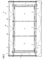
- Fig. 2 shows a side view of a 3-leg-transformer 21.
- the core 20 has three core legs 17. On each core leg 17 a coil 4 is attached.
- the clamping structure 14 keeps the coils together.
- the magnetic material of the inner core loop 16 and the side core loop 6 is an amorphous alloy.
- a supporting element 1 is installed in each window 12 of a side core loop 6 .
- the supporting element 1 extends from the upper supporting frame 2 to the lower supporting frame 3.
- Both supporting frames 2 and 3 are arranged in a horizontal direction and in parallel to each other. Since the plates 1 are installed in the window 12 of the side core loops 6 they have to be electrically insulated from the supporting frames 2, 3. Therefore an insulation 7 is applied at the joining area between the extensions 15 of the supporting plate 1 and the frames 2, 3.
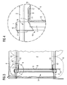
- Fig. 3 is a side view of a core segment of the 3-leg-transformer showing the side core loop 6.
- the supporting structure 1 is in tight contact with the outer circumferential surface 9 of the winding 4. This clamping of the winding structure 4 reduces the displacement of the coils during transient operation of the transformer. Between the supporting structure 1 and the circumferential surface 9 of the windings 4 an electric insulation 8 is arranged.
- Fig. 4 is an enlarged view of detail "X" in Fig. 3 .
- the extension 15 projects in the recess 18 and is surrounded by insulation 7 and fixed by the wedge 5.
- the plane area 13 of the coil and the supporting element 1 is separated by the insulation 8.
- Two radial extensions 11 of the supporting plate 1 hold the coil 4 in the window 12 of the core 20.
- the insulation 8 extends also in radial direction and separates the radial extension 11 and the adjacent end surface 11 of the coil 4. For safety reason each wedge 5 is secured in the recess 18 by an adhesive.
- Fig. 5 is a top view of a core segment of the 3-leg-transformer showing the area of the side core loop 6.
- the winding 4 has rectangular cross section with rounded edges.
- the contact area of supporting element 1 is a plane structure. As mentioned above, this plane structure 1 of the supporting element is in tight contact with the plane area 13 of the circumferential surface 9 of the coil 4. The wedging generates a radial force pressing the supporting element 1 on to the plane area 13. The winding structure 4 is clamped between the lateral supporting elements 1.
- Fig. 6 shows detail "Y" of Fig. 5 in an enlarged view.
- the recess 18 is of rectangular shape.
- the extension 15 in the recess 18 is surrounded by insulation 7.
- the wedge 5 is pressing the supporting element 1 in direction of the coil 4 (in fig. 6 from left to right).
- the clamping structure 14 is adjustable in respect of the distance between the supporting plates 1 and plain area 13 of the coil 4 by wedging 5.
- Fig. 7 shows a perspective view of a supporting element 1.
- the supporting element 1 essentially consists of plane area. On each end section 22 there are two extensions 15. To increase the section modulus of element 1 the edge of plane area shows a deflection.
- the supporting element 1 is made of steel.
- a transformer according to the invention can be manufactured by a process comprising the steps:
- the invention provides sufficient support of the windings against dynamic forces which makes the winding structure 4 "short-circuit-proof". In case of a short circuit the core 20 is not damaged. During operation of the transformer displacement of the windings is reduced. Dynamic forces of the winding have a reduced effect on the magnetic properties of the amorphous magnetic material.
Landscapes
- Engineering & Computer Science (AREA)
- Power Engineering (AREA)
- Coils Of Transformers For General Uses (AREA)
- Manufacturing Cores, Coils, And Magnets (AREA)
- Coils Or Transformers For Communication (AREA)
Description
- The present invention relates to electrical transformer and particularly to transformers having cores made from amorphous metal alloys.
- Traditionally, electrical transformer cores have been formed of grain oriented silicon steel laminations. With the introduction of high grain oriented silicon steel operating losses could be reduced. However, cost of electrical energy continues to rise and reductions in magnetic losses have become an increasingly important design consideration in all sizes of transformers used in an electrical distribution system.
- Amorphous metals have a non-crystalline structure. Used as transformer core materials, core operating losses can be reduced dramatically. Such amorphous ferromagnetic strip is extremely thin, normally one mil versus ten mils of grain oriented silicon steel. Amorphous steel lamination is very brittle and easy fractured. Moreover, the magnetic properties of amorphous metals have been found to be deleteriously affected by mechanical stress during manufacturing of the transformer, e.g. mechanical fixing force crated by clamping the coil in the core window. In addition, mechanical stress acts on the transformer core because of displacement of the windings during transient operations of the transformer. In case of a short circuit dynamic forces can be very high.
- Especially in the case of shell-type-transformers with 5 core legs there is no proper solution for radial support of the windings.
- In power transformers based on amorphous metal cores it is usual, to have the core carrying the coils directly (
DE 195 05 529 A1 ,DE 27 53 952 A1 ) or to have the coils carried indirectly by a separate structure (WO 2010/102669 A1 ). - It is accordingly an object of the present invention to provide an amorphous metal transformer where magnetic properties of the amorphous core materiel are less affected by mechanical forces caused by static and dynamic displacement of the windings.
- A still further object is to provide a method of manufacturing an amorphous transformer.
- In accordance with the present invention there is provided a transformer with an amorphous core. Attached to core legs is a winding structure. In order to reduce mechanical stress of the core caused by dynamic and / or static displacement of the winding structure during transient operation of the transformer a clamping structure is provided. The clamping structure essentially consists of at least two supporting elements. These supporting elements are fastened in the upper and lower supporting frame of the transformer by wedging. The wedging acts as an adjustable mechanical linkage between supporting element and the frame. This linkage allows to adept the clamping structure to permissible variations in the radial dimensions of the winding structure. The winding structure is clamped between supporting plates located in the window of the transformer core.
- In the accompanying drawing,
- Fig. 1
- is a perspective view showing a clamping structure applied to windings of 3-leg-transformer;
- Fig. 2
- is a side view of the 3-leg-transformer;
- Fig. 3
- is a side view of a core segment of a transformer showing a side core loop;
- Fig. 4
- is an enlarged view of detail "X" in
Fig. 3 - Fig. 5
- is a top view of a core segment of a transformer showing a side core loop;
- Fig. 6
- is an enlarged view of detail "Y" in
Fig. 5 ; - Fig. 7
- is a perspective view of a supporting element.
-
Fig. 1 is a perspective view showing aclamping structure 14 applied towindings 4 of a 3-leg-transformer 21 (the core of the transformer is not shown inFig. 1 ). To keep the threecoils 4 together the winding structure is fastened between the two ridged supportingelements 1. Thewinding structure 4 is sandwiched between the supporting elements. A upper supportingframe 2 and a lower supportingframe 3 are fixed by tie rods.Fig. 1 shows the two supportingelements 1 in a mounted position. Eachside element 1 is attached laterally on aouter winding 4. Each supportingelement 1 hasend sections 22 withvertical extensions 15. In the mounted position (Fig. 1 ) eachextension 15 projects into acorresponding recess 18 provided in the upper and lower supportingframe extension 15 is fastened in therecess 18 by awedge 5. This wedging allows adjustment of the distance between the two supportingelements 1 relative to theouter coil 4. Since the dimension of acoil 4 can vary within approximately 2-3 mm it is necessary to adept theclamping structure 14 to these permissible variations in the size of thewinding structure 4. The supportingelements 1 act in radial direction on theouter coils 4. During transient operations of the transformer the influence of variations in the shape of thecoil 4 is limited by theclamping structure 14. Prejudice of magnetic properties of the amorphous magnetic material is reduced. -
Fig. 2 shows a side view of a 3-leg-transformer 21. Thecore 20 has threecore legs 17. On each core leg 17 acoil 4 is attached. Theclamping structure 14 keeps the coils together. The magnetic material of theinner core loop 16 and theside core loop 6 is an amorphous alloy. In eachwindow 12 of a side core loop 6 a supportingelement 1 is installed. The supportingelement 1 extends from the upper supportingframe 2 to the lower supportingframe 3. Both supportingframes plates 1 are installed in thewindow 12 of theside core loops 6 they have to be electrically insulated from the supportingframes insulation 7 is applied at the joining area between theextensions 15 of the supportingplate 1 and theframes -
Fig. 3 is a side view of a core segment of the 3-leg-transformer showing theside core loop 6. The supportingstructure 1 is in tight contact with the outer circumferential surface 9 of the winding 4. This clamping of the windingstructure 4 reduces the displacement of the coils during transient operation of the transformer. Between the supportingstructure 1 and the circumferential surface 9 of thewindings 4 anelectric insulation 8 is arranged. -
Fig. 4 is an enlarged view of detail "X" inFig. 3 . Theextension 15 projects in therecess 18 and is surrounded byinsulation 7 and fixed by thewedge 5. Theplane area 13 of the coil and the supportingelement 1 is separated by theinsulation 8. Tworadial extensions 11 of the supportingplate 1 hold thecoil 4 in thewindow 12 of thecore 20. Theinsulation 8 extends also in radial direction and separates theradial extension 11 and theadjacent end surface 11 of thecoil 4. For safety reason eachwedge 5 is secured in therecess 18 by an adhesive. -
Fig. 5 is a top view of a core segment of the 3-leg-transformer showing the area of theside core loop 6. The winding 4 has rectangular cross section with rounded edges. The contact area of supportingelement 1 is a plane structure. As mentioned above, thisplane structure 1 of the supporting element is in tight contact with theplane area 13 of the circumferential surface 9 of thecoil 4. The wedging generates a radial force pressing the supportingelement 1 on to theplane area 13. The windingstructure 4 is clamped between thelateral supporting elements 1. -
Fig. 6 shows detail "Y" ofFig. 5 in an enlarged view. Therecess 18 is of rectangular shape. Theextension 15 in therecess 18 is surrounded byinsulation 7. Thewedge 5 is pressing the supportingelement 1 in direction of the coil 4 (infig. 6 from left to right). As already mentioned, the clampingstructure 14 is adjustable in respect of the distance between the supportingplates 1 andplain area 13 of thecoil 4 by wedging 5. -
Fig. 7 shows a perspective view of a supportingelement 1. The supportingelement 1 essentially consists of plane area. On eachend section 22 there are twoextensions 15. To increase the section modulus ofelement 1 the edge of plane area shows a deflection. The supportingelement 1 is made of steel. - A transformer according to the invention can be manufactured by a process comprising the steps:
- a. forming a winding structure (4) having a circumferential surface (9);
- b. fixing a insulation (8) on the surface (9);
- c. providing at least two supporting elements (1) having end sections (22) with extensions (15);
- d. fixing an insulation (7) on each extension (15);
- e. providing a opened side core loop (6) made of laminations of amorphous material;
- f. inserting the opened side core loop (6) into the winding structure (4);
- g. closing lamination of side core loop (6);
- h. providing a first supporting frame (2) and a second supporting frame (3), each supporting frame (2, 3) having recesses (8);
- i. fixing an insulation (7) between a supporting plate (1) and a winding structure (4);
- j. joining the first supporting frame (2) and the second supporting frame (3), whereby each extension (15) is put into a corresponding recess (18) and whereby the winding structure (4) is clamped between the first supporting frame (2) and the second supporting frame (3) by tie rods;
- k. inserting a wedge (5) in each recess (18);
- l. applying a force on the wedge (5) in order clamp the windings structure (4) between the supporting plates (1).
- The invention provides sufficient support of the windings against dynamic forces which makes the winding
structure 4 "short-circuit-proof". In case of a short circuit thecore 20 is not damaged. During operation of the transformer displacement of the windings is reduced. Dynamic forces of the winding have a reduced effect on the magnetic properties of the amorphous magnetic material. - The foregoing merely illustrates the principal of the invention. Those skilled in the art will be able to diverse numerous arrangements which, although not explicitly described or shown herein, embody those principles and are within the scope of the invention.
-
- 1
- supporting element
- 2
- first supporting frame, upper frame
- 3
- second supporting frame, lower frame
- 4
- winding structure, coil
- 5
- wedge
- 6
- side core loop
- 7
- insulation between 1 and 2
- 8
- insulation between 1 and 4
- 9
- circumferential surface of the coil
- 10
- end-surface of the coil
- 11
- radial extension
- 12
- window
- 13
- plane area of 9
- 14
- clamping structure
- 15
- extension of 1
- 16
- inner core loop
- 17
- core leg
- 18
- recess
- 19
- 20
- core
- 21
- 3-leg-transformer
- 22
- end section
Claims (10)
- Amorphous metal transformer, comprising:a magnetic core (20), the core (20) comprising a core leg (17) with a winding structure (4) attached to this leg (17), the winding structure (4) having an outer circumferential surface (9), whereby the outer circumferential surface (9) has a plane area (13) located in a window (12) of the core (20);a clamping structure (14), arranged to reduce mechanical stress of the core (20) caused by the dynamic and / or static displacement of the winding structure during transient operations of the transformer, the clamping structure (14) comprising:- a first supporting frame (2);- a second supporting frame (3);- at least two supporting elements (1), dedicated to the winding structure (4), wherein each supporting element (1) supports the plane area (13) of the outer circumferential surface (9) of the winding structure (4);- means for adjustably interconnecting each supporting element (1) with the first supporting frame (2) and the second supporting frame (3).
- Transformer as claimed in Claim 1, wherein the means for adjustably interconnecting each supporting element (1) with the first supporting frame (2) and the second supporting frame (3) comprises a wedging.
- Transformer as claimed in to Claim 2, wherein the wedging comprises a wedge (5) which is in a mounted position inserted in a corresponding recess (18) provided in the first supporting frame (2) and the second supporting frame (3) configured to press the supporting element (1) against the plane area (13).
- Transformer as claimed in Claim 3, further comprising an insulation (7) configured to separate electrically the extension (15) and the corresponding supporting frame (2, 3).
- Transformer as claimed in Claim 3, wherein, in the mounted position, the wedge (5) is arranged to taper in plumb line.
- Transformer as claimed in Claim 3, wherein, in the mounted position, the wedge (5) is fixed in the recess (18) by an adhesive.
- Transformer as claimed in Claim 1, wherein the at least two supporting elements (1) are C-shaped, having radial extensions (11), whereby in the mounting position each of these radial extensions (11) support a lateral subarea of a dedicated end-surface (10) of the winding structure (4).
- Transformer as claimed in Claim 1, wherein the at least two supporting elements (1) are arranged essentially parallel to each other.
- Transformer as claimed in Claim 1, wherein each supporting element (1) has end sections (22) having two extensions (15) and wherein in a mounting position each extension is fixed in a corresponding recess (18) by a wedge (5).
- A method of manufacturing an amorphous transformer comprising the steps of:a. forming a winding structure(4) having a circumferential surface (9);b. fixing an insulation (8) on, the surface (9) ;c. providing at least two supporting elements (1) having end sections (22) with extensions (15);d. fixing an insulation (7) on each extension (15);e. providing an opened side core loop (6) made of laminations of amorphous material;f. inserting the opened side core loop (6) into the winding structure;g. closing the lamination of the side core loop (6);h. providing a first supporting frame (2) and a second supporting frame (3), each supporting frame (2, 3) having recesses (8);i. fixing an insulation (7) between a supporting plate (1) and the winding structure (4);j. joining the first supporting frame (2) and the second supporting frame (3), whereby each extension (15) is put into a corresponding recess (18) and whereby the winding structure (4) is clamped between the first supporting frame (2) and the second supporting frame (3) by tie rods;k. inserting a wedge (5) in each recess (18);l. fastening by applying a force on the wedge (5).
Priority Applications (1)
| Application Number | Priority Date | Filing Date | Title |
|---|---|---|---|
| PL11704748T PL2673790T3 (en) | 2011-02-08 | 2011-02-08 | Amorphous metal transformer |
Applications Claiming Priority (1)
| Application Number | Priority Date | Filing Date | Title |
|---|---|---|---|
| PCT/EP2011/051809 WO2012107078A1 (en) | 2011-02-08 | 2011-02-08 | Amorphous metal transformer |
Publications (2)
| Publication Number | Publication Date |
|---|---|
| EP2673790A1 EP2673790A1 (en) | 2013-12-18 |
| EP2673790B1 true EP2673790B1 (en) | 2015-04-01 |
Family
ID=43923629
Family Applications (1)
| Application Number | Title | Priority Date | Filing Date |
|---|---|---|---|
| EP11704748.0A Not-in-force EP2673790B1 (en) | 2011-02-08 | 2011-02-08 | Amorphous metal transformer |
Country Status (5)
| Country | Link |
|---|---|
| EP (1) | EP2673790B1 (en) |
| CN (1) | CN103348424B (en) |
| ES (1) | ES2536958T3 (en) |
| PL (1) | PL2673790T3 (en) |
| WO (1) | WO2012107078A1 (en) |
Families Citing this family (3)
| Publication number | Priority date | Publication date | Assignee | Title |
|---|---|---|---|---|
| KR102018867B1 (en) * | 2015-03-31 | 2019-09-09 | 현대일렉트릭앤에너지시스템(주) | Shunt reactor core fixing device |
| CN109786068B (en) * | 2019-01-31 | 2024-04-16 | 上海置信电气非晶有限公司 | Impact-resistant supporting structure applied to amorphous planar coiled iron core body and transformer |
| KR102699497B1 (en) * | 2023-03-29 | 2024-08-30 | 에이치디현대일렉트릭 주식회사 | Reactor |
Family Cites Families (5)
| Publication number | Priority date | Publication date | Assignee | Title |
|---|---|---|---|---|
| SE403208B (en) * | 1976-12-14 | 1978-07-31 | Asea Ab | DEVICE FOR RECEIVING SHORT CIRCUIT FORCES IN POWER TRANSFORMERS |
| DE19505529A1 (en) * | 1994-12-24 | 1996-06-27 | Abb Patent Gmbh | Three=phase power transformer with load-bearing rated coil former |
| BRPI0924023B1 (en) * | 2009-03-12 | 2024-04-30 | Hitachi Energy Ltd | ELECTRICAL TRANSFORMER WITH AN IMPROVED COOLING SYSTEM |
| CN201489974U (en) * | 2009-06-15 | 2010-05-26 | 苏州工业园区隆盛电器成套设备制造有限公司 | Lateral side compression structure of transformer body with rectangle roll iron core structure |
| CN201478078U (en) * | 2009-07-31 | 2010-05-19 | 杭州钱江电气集团股份有限公司 | Amorphous alloy distribution transformer and inner core thereof |
-
2011
- 2011-02-08 ES ES11704748.0T patent/ES2536958T3/en active Active
- 2011-02-08 WO PCT/EP2011/051809 patent/WO2012107078A1/en not_active Ceased
- 2011-02-08 PL PL11704748T patent/PL2673790T3/en unknown
- 2011-02-08 EP EP11704748.0A patent/EP2673790B1/en not_active Not-in-force
- 2011-02-08 CN CN201180067093.4A patent/CN103348424B/en active Active
Also Published As
| Publication number | Publication date |
|---|---|
| CN103348424A (en) | 2013-10-09 |
| ES2536958T3 (en) | 2015-06-01 |
| PL2673790T3 (en) | 2015-09-30 |
| CN103348424B (en) | 2016-11-09 |
| WO2012107078A9 (en) | 2013-08-08 |
| WO2012107078A1 (en) | 2012-08-16 |
| EP2673790A1 (en) | 2013-12-18 |
Similar Documents
| Publication | Publication Date | Title |
|---|---|---|
| US10978237B2 (en) | Core for stationary induction apparatus | |
| EP2590187A2 (en) | Amorphous core transformer | |
| CN101388279B (en) | A shell-type amorphous alloy transformer body | |
| JP6453120B2 (en) | Transformer | |
| US8610318B2 (en) | Moving magnet actuator magnet carrier | |
| JP6198978B2 (en) | Transformer | |
| US10199913B2 (en) | Primary part for a linear motor, a linear motor comprising the same, and method for manufacturing such primary part | |
| WO2012107078A1 (en) | Amorphous metal transformer | |
| JP6407549B2 (en) | Static induction machine | |
| JP6158579B2 (en) | Static induction machine | |
| JP5969755B2 (en) | Amorphous iron core transformer | |
| JP2010171313A (en) | Stationary induction electrical apparatus | |
| KR20160052214A (en) | Structure of Tie Plate of Transformer | |
| US9142349B2 (en) | Method for achieving converter transformer for DC magnetic bias | |
| CN204066967U (en) | Shell type reactor | |
| KR102135201B1 (en) | Transformer | |
| CN102388424A (en) | Power transformer with amorphous core | |
| JP6491835B2 (en) | Static induction machine | |
| US20180358160A1 (en) | Stationary Induction Apparatus | |
| JP2019029505A (en) | Transformer core support structure | |
| CN102867708A (en) | Short circuit trigger with optimised coil connection | |
| CN103827995A (en) | Press frame structure for a transformer | |
| JP7032257B2 (en) | Transformers and steel cores | |
| JP2012004345A (en) | Stationary induction apparatus and method of manufacturing the same | |
| JP2016207845A (en) | Static induction machine |
Legal Events
| Date | Code | Title | Description |
|---|---|---|---|
| PUAI | Public reference made under article 153(3) epc to a published international application that has entered the european phase |
Free format text: ORIGINAL CODE: 0009012 |
|
| 17P | Request for examination filed |
Effective date: 20130620 |
|
| AK | Designated contracting states |
Kind code of ref document: A1 Designated state(s): AL AT BE BG CH CY CZ DE DK EE ES FI FR GB GR HR HU IE IS IT LI LT LU LV MC MK MT NL NO PL PT RO RS SE SI SK SM TR |
|
| DAX | Request for extension of the european patent (deleted) | ||
| GRAP | Despatch of communication of intention to grant a patent |
Free format text: ORIGINAL CODE: EPIDOSNIGR1 |
|
| INTG | Intention to grant announced |
Effective date: 20141024 |
|
| GRAS | Grant fee paid |
Free format text: ORIGINAL CODE: EPIDOSNIGR3 |
|
| GRAA | (expected) grant |
Free format text: ORIGINAL CODE: 0009210 |
|
| AK | Designated contracting states |
Kind code of ref document: B1 Designated state(s): AL AT BE BG CH CY CZ DE DK EE ES FI FR GB GR HR HU IE IS IT LI LT LU LV MC MK MT NL NO PL PT RO RS SE SI SK SM TR |
|
| REG | Reference to a national code |
Ref country code: GB Ref legal event code: FG4D |
|
| REG | Reference to a national code |
Ref country code: CH Ref legal event code: EP |
|
| REG | Reference to a national code |
Ref country code: IE Ref legal event code: FG4D |
|
| REG | Reference to a national code |
Ref country code: DE Ref legal event code: R096 Ref document number: 602011015213 Country of ref document: DE Effective date: 20150513 |
|
| REG | Reference to a national code |
Ref country code: AT Ref legal event code: REF Ref document number: 719504 Country of ref document: AT Kind code of ref document: T Effective date: 20150515 |
|
| REG | Reference to a national code |
Ref country code: ES Ref legal event code: FG2A Ref document number: 2536958 Country of ref document: ES Kind code of ref document: T3 Effective date: 20150601 |
|
| REG | Reference to a national code |
Ref country code: SE Ref legal event code: TRGR |
|
| REG | Reference to a national code |
Ref country code: NL Ref legal event code: VDEP Effective date: 20150401 |
|
| REG | Reference to a national code |
Ref country code: AT Ref legal event code: MK05 Ref document number: 719504 Country of ref document: AT Kind code of ref document: T Effective date: 20150401 |
|
| REG | Reference to a national code |
Ref country code: LT Ref legal event code: MG4D |
|
| PG25 | Lapsed in a contracting state [announced via postgrant information from national office to epo] |
Ref country code: NL Free format text: LAPSE BECAUSE OF FAILURE TO SUBMIT A TRANSLATION OF THE DESCRIPTION OR TO PAY THE FEE WITHIN THE PRESCRIBED TIME-LIMIT Effective date: 20150401 |
|
| REG | Reference to a national code |
Ref country code: PL Ref legal event code: T3 |
|
| PG25 | Lapsed in a contracting state [announced via postgrant information from national office to epo] |
Ref country code: CZ Free format text: LAPSE BECAUSE OF FAILURE TO SUBMIT A TRANSLATION OF THE DESCRIPTION OR TO PAY THE FEE WITHIN THE PRESCRIBED TIME-LIMIT Effective date: 20150401 Ref country code: FI Free format text: LAPSE BECAUSE OF FAILURE TO SUBMIT A TRANSLATION OF THE DESCRIPTION OR TO PAY THE FEE WITHIN THE PRESCRIBED TIME-LIMIT Effective date: 20150401 Ref country code: PT Free format text: LAPSE BECAUSE OF FAILURE TO SUBMIT A TRANSLATION OF THE DESCRIPTION OR TO PAY THE FEE WITHIN THE PRESCRIBED TIME-LIMIT Effective date: 20150803 Ref country code: NO Free format text: LAPSE BECAUSE OF FAILURE TO SUBMIT A TRANSLATION OF THE DESCRIPTION OR TO PAY THE FEE WITHIN THE PRESCRIBED TIME-LIMIT Effective date: 20150701 Ref country code: HR Free format text: LAPSE BECAUSE OF FAILURE TO SUBMIT A TRANSLATION OF THE DESCRIPTION OR TO PAY THE FEE WITHIN THE PRESCRIBED TIME-LIMIT Effective date: 20150401 Ref country code: LT Free format text: LAPSE BECAUSE OF FAILURE TO SUBMIT A TRANSLATION OF THE DESCRIPTION OR TO PAY THE FEE WITHIN THE PRESCRIBED TIME-LIMIT Effective date: 20150401 |
|
| PG25 | Lapsed in a contracting state [announced via postgrant information from national office to epo] |
Ref country code: AT Free format text: LAPSE BECAUSE OF FAILURE TO SUBMIT A TRANSLATION OF THE DESCRIPTION OR TO PAY THE FEE WITHIN THE PRESCRIBED TIME-LIMIT Effective date: 20150401 Ref country code: IS Free format text: LAPSE BECAUSE OF FAILURE TO SUBMIT A TRANSLATION OF THE DESCRIPTION OR TO PAY THE FEE WITHIN THE PRESCRIBED TIME-LIMIT Effective date: 20150801 Ref country code: GR Free format text: LAPSE BECAUSE OF FAILURE TO SUBMIT A TRANSLATION OF THE DESCRIPTION OR TO PAY THE FEE WITHIN THE PRESCRIBED TIME-LIMIT Effective date: 20150702 Ref country code: RS Free format text: LAPSE BECAUSE OF FAILURE TO SUBMIT A TRANSLATION OF THE DESCRIPTION OR TO PAY THE FEE WITHIN THE PRESCRIBED TIME-LIMIT Effective date: 20150401 Ref country code: LV Free format text: LAPSE BECAUSE OF FAILURE TO SUBMIT A TRANSLATION OF THE DESCRIPTION OR TO PAY THE FEE WITHIN THE PRESCRIBED TIME-LIMIT Effective date: 20150401 |
|
| REG | Reference to a national code |
Ref country code: HU Ref legal event code: AG4A Ref document number: E024801 Country of ref document: HU |
|
| REG | Reference to a national code |
Ref country code: DE Ref legal event code: R097 Ref document number: 602011015213 Country of ref document: DE |
|
| PG25 | Lapsed in a contracting state [announced via postgrant information from national office to epo] |
Ref country code: DK Free format text: LAPSE BECAUSE OF FAILURE TO SUBMIT A TRANSLATION OF THE DESCRIPTION OR TO PAY THE FEE WITHIN THE PRESCRIBED TIME-LIMIT Effective date: 20150401 Ref country code: EE Free format text: LAPSE BECAUSE OF FAILURE TO SUBMIT A TRANSLATION OF THE DESCRIPTION OR TO PAY THE FEE WITHIN THE PRESCRIBED TIME-LIMIT Effective date: 20150401 |
|
| PLBE | No opposition filed within time limit |
Free format text: ORIGINAL CODE: 0009261 |
|
| STAA | Information on the status of an ep patent application or granted ep patent |
Free format text: STATUS: NO OPPOSITION FILED WITHIN TIME LIMIT |
|
| REG | Reference to a national code |
Ref country code: FR Ref legal event code: PLFP Year of fee payment: 6 |
|
| PG25 | Lapsed in a contracting state [announced via postgrant information from national office to epo] |
Ref country code: RO Free format text: LAPSE BECAUSE OF NON-PAYMENT OF DUE FEES Effective date: 20150401 Ref country code: SK Free format text: LAPSE BECAUSE OF FAILURE TO SUBMIT A TRANSLATION OF THE DESCRIPTION OR TO PAY THE FEE WITHIN THE PRESCRIBED TIME-LIMIT Effective date: 20150401 |
|
| 26N | No opposition filed |
Effective date: 20160105 |
|
| PG25 | Lapsed in a contracting state [announced via postgrant information from national office to epo] |
Ref country code: IT Free format text: LAPSE BECAUSE OF FAILURE TO SUBMIT A TRANSLATION OF THE DESCRIPTION OR TO PAY THE FEE WITHIN THE PRESCRIBED TIME-LIMIT Effective date: 20150401 |
|
| PG25 | Lapsed in a contracting state [announced via postgrant information from national office to epo] |
Ref country code: SI Free format text: LAPSE BECAUSE OF FAILURE TO SUBMIT A TRANSLATION OF THE DESCRIPTION OR TO PAY THE FEE WITHIN THE PRESCRIBED TIME-LIMIT Effective date: 20150401 |
|
| PG25 | Lapsed in a contracting state [announced via postgrant information from national office to epo] |
Ref country code: LU Free format text: LAPSE BECAUSE OF FAILURE TO SUBMIT A TRANSLATION OF THE DESCRIPTION OR TO PAY THE FEE WITHIN THE PRESCRIBED TIME-LIMIT Effective date: 20160208 Ref country code: MC Free format text: LAPSE BECAUSE OF FAILURE TO SUBMIT A TRANSLATION OF THE DESCRIPTION OR TO PAY THE FEE WITHIN THE PRESCRIBED TIME-LIMIT Effective date: 20150401 |
|
| REG | Reference to a national code |
Ref country code: CH Ref legal event code: PL |
|
| GBPC | Gb: european patent ceased through non-payment of renewal fee |
Effective date: 20160208 |
|
| PG25 | Lapsed in a contracting state [announced via postgrant information from national office to epo] |
Ref country code: LI Free format text: LAPSE BECAUSE OF NON-PAYMENT OF DUE FEES Effective date: 20160229 Ref country code: CH Free format text: LAPSE BECAUSE OF NON-PAYMENT OF DUE FEES Effective date: 20160229 |
|
| REG | Reference to a national code |
Ref country code: IE Ref legal event code: MM4A |
|
| PG25 | Lapsed in a contracting state [announced via postgrant information from national office to epo] |
Ref country code: IE Free format text: LAPSE BECAUSE OF NON-PAYMENT OF DUE FEES Effective date: 20160208 Ref country code: GB Free format text: LAPSE BECAUSE OF NON-PAYMENT OF DUE FEES Effective date: 20160208 |
|
| REG | Reference to a national code |
Ref country code: FR Ref legal event code: PLFP Year of fee payment: 7 |
|
| PG25 | Lapsed in a contracting state [announced via postgrant information from national office to epo] |
Ref country code: MT Free format text: LAPSE BECAUSE OF FAILURE TO SUBMIT A TRANSLATION OF THE DESCRIPTION OR TO PAY THE FEE WITHIN THE PRESCRIBED TIME-LIMIT Effective date: 20150401 |
|
| REG | Reference to a national code |
Ref country code: FR Ref legal event code: PLFP Year of fee payment: 8 |
|
| PG25 | Lapsed in a contracting state [announced via postgrant information from national office to epo] |
Ref country code: SM Free format text: LAPSE BECAUSE OF FAILURE TO SUBMIT A TRANSLATION OF THE DESCRIPTION OR TO PAY THE FEE WITHIN THE PRESCRIBED TIME-LIMIT Effective date: 20150401 Ref country code: CY Free format text: LAPSE BECAUSE OF FAILURE TO SUBMIT A TRANSLATION OF THE DESCRIPTION OR TO PAY THE FEE WITHIN THE PRESCRIBED TIME-LIMIT Effective date: 20150401 |
|
| PG25 | Lapsed in a contracting state [announced via postgrant information from national office to epo] |
Ref country code: MK Free format text: LAPSE BECAUSE OF FAILURE TO SUBMIT A TRANSLATION OF THE DESCRIPTION OR TO PAY THE FEE WITHIN THE PRESCRIBED TIME-LIMIT Effective date: 20150401 Ref country code: TR Free format text: LAPSE BECAUSE OF FAILURE TO SUBMIT A TRANSLATION OF THE DESCRIPTION OR TO PAY THE FEE WITHIN THE PRESCRIBED TIME-LIMIT Effective date: 20150401 Ref country code: MT Free format text: LAPSE BECAUSE OF FAILURE TO SUBMIT A TRANSLATION OF THE DESCRIPTION OR TO PAY THE FEE WITHIN THE PRESCRIBED TIME-LIMIT Effective date: 20160229 |
|
| PG25 | Lapsed in a contracting state [announced via postgrant information from national office to epo] |
Ref country code: BG Free format text: LAPSE BECAUSE OF FAILURE TO SUBMIT A TRANSLATION OF THE DESCRIPTION OR TO PAY THE FEE WITHIN THE PRESCRIBED TIME-LIMIT Effective date: 20150401 |
|
| PG25 | Lapsed in a contracting state [announced via postgrant information from national office to epo] |
Ref country code: AL Free format text: LAPSE BECAUSE OF FAILURE TO SUBMIT A TRANSLATION OF THE DESCRIPTION OR TO PAY THE FEE WITHIN THE PRESCRIBED TIME-LIMIT Effective date: 20150401 |
|
| REG | Reference to a national code |
Ref country code: DE Ref legal event code: R081 Ref document number: 602011015213 Country of ref document: DE Owner name: SIEMENS ENERGY GLOBAL GMBH & CO. KG, DE Free format text: FORMER OWNER: SIEMENS AKTIENGESELLSCHAFT, 80333 MUENCHEN, DE |
|
| REG | Reference to a national code |
Ref country code: HU Ref legal event code: GB9C Owner name: SIEMENS ENERGY GLOBAL GMBH & CO. KG, DE Free format text: FORMER OWNER(S): SIEMENS AKTIENGESELLSCHAFT, DE Ref country code: HU Ref legal event code: FH1C Free format text: FORMER REPRESENTATIVE(S): MAK ANDRAS, SBGK SZABADALMI UEGYVIVOEI IRODA, HU Representative=s name: SBGK SZABADALMI UEGYVIVOEI IRODA, HU |
|
| REG | Reference to a national code |
Ref country code: BE Ref legal event code: PD Owner name: SIEMENS ENERGY GLOBAL GMBH & CO. KG; DE Free format text: DETAILS ASSIGNMENT: CHANGE OF OWNER(S), ASSIGNMENT; FORMER OWNER NAME: SIEMENS AKTIENGESELLSCHAFT Effective date: 20230125 |
|
| PGFP | Annual fee paid to national office [announced via postgrant information from national office to epo] |
Ref country code: FR Payment date: 20230221 Year of fee payment: 13 Ref country code: ES Payment date: 20230321 Year of fee payment: 13 |
|
| PGFP | Annual fee paid to national office [announced via postgrant information from national office to epo] |
Ref country code: SE Payment date: 20230208 Year of fee payment: 13 Ref country code: PL Payment date: 20230127 Year of fee payment: 13 Ref country code: HU Payment date: 20230303 Year of fee payment: 13 Ref country code: DE Payment date: 20220617 Year of fee payment: 13 Ref country code: BE Payment date: 20230216 Year of fee payment: 13 |
|
| REG | Reference to a national code |
Ref country code: ES Ref legal event code: PC2A Owner name: SIEMENS ENERGY GLOBAL GMBH & CO. KG Effective date: 20240403 |
|
| REG | Reference to a national code |
Ref country code: DE Ref legal event code: R119 Ref document number: 602011015213 Country of ref document: DE |
|
| REG | Reference to a national code |
Ref country code: SE Ref legal event code: EUG |
|
| PG25 | Lapsed in a contracting state [announced via postgrant information from national office to epo] |
Ref country code: HU Free format text: LAPSE BECAUSE OF NON-PAYMENT OF DUE FEES Effective date: 20240209 |
|
| PG25 | Lapsed in a contracting state [announced via postgrant information from national office to epo] |
Ref country code: HU Free format text: LAPSE BECAUSE OF NON-PAYMENT OF DUE FEES Effective date: 20240209 |
|
| REG | Reference to a national code |
Ref country code: BE Ref legal event code: MM Effective date: 20240229 |
|
| PG25 | Lapsed in a contracting state [announced via postgrant information from national office to epo] |
Ref country code: DE Free format text: LAPSE BECAUSE OF NON-PAYMENT OF DUE FEES Effective date: 20240903 |
|
| PG25 | Lapsed in a contracting state [announced via postgrant information from national office to epo] |
Ref country code: BE Free format text: LAPSE BECAUSE OF NON-PAYMENT OF DUE FEES Effective date: 20240229 |
|
| PG25 | Lapsed in a contracting state [announced via postgrant information from national office to epo] |
Ref country code: FR Free format text: LAPSE BECAUSE OF NON-PAYMENT OF DUE FEES Effective date: 20240229 |
|
| PG25 | Lapsed in a contracting state [announced via postgrant information from national office to epo] |
Ref country code: FR Free format text: LAPSE BECAUSE OF NON-PAYMENT OF DUE FEES Effective date: 20240229 Ref country code: DE Free format text: LAPSE BECAUSE OF NON-PAYMENT OF DUE FEES Effective date: 20240903 Ref country code: BE Free format text: LAPSE BECAUSE OF NON-PAYMENT OF DUE FEES Effective date: 20240229 |
|
| REG | Reference to a national code |
Ref country code: ES Ref legal event code: FD2A Effective date: 20250326 |
|
| PG25 | Lapsed in a contracting state [announced via postgrant information from national office to epo] |
Ref country code: ES Free format text: LAPSE BECAUSE OF NON-PAYMENT OF DUE FEES Effective date: 20240209 |
|
| PG25 | Lapsed in a contracting state [announced via postgrant information from national office to epo] |
Ref country code: PL Free format text: LAPSE BECAUSE OF NON-PAYMENT OF DUE FEES Effective date: 20240208 |
|
| PG25 | Lapsed in a contracting state [announced via postgrant information from national office to epo] |
Ref country code: SE Free format text: LAPSE BECAUSE OF NON-PAYMENT OF DUE FEES Effective date: 20240209 |