EP2673627B1 - Two-dimensional gel electrophoresis apparatus and method - Google Patents
Two-dimensional gel electrophoresis apparatus and method Download PDFInfo
- Publication number
- EP2673627B1 EP2673627B1 EP12712143.2A EP12712143A EP2673627B1 EP 2673627 B1 EP2673627 B1 EP 2673627B1 EP 12712143 A EP12712143 A EP 12712143A EP 2673627 B1 EP2673627 B1 EP 2673627B1
- Authority
- EP
- European Patent Office
- Prior art keywords
- electrodes
- electrophoresis
- edges
- group
- gel
- Prior art date
- Legal status (The legal status is an assumption and is not a legal conclusion. Google has not performed a legal analysis and makes no representation as to the accuracy of the status listed.)
- Not-in-force
Links
- 238000000034 method Methods 0.000 title claims description 25
- 238000000539 two dimensional gel electrophoresis Methods 0.000 title claims description 25
- 238000001962 electrophoresis Methods 0.000 claims description 120
- 230000005684 electric field Effects 0.000 claims description 34
- 239000003795 chemical substances by application Substances 0.000 claims description 13
- 108020004707 nucleic acids Proteins 0.000 claims description 9
- 102000039446 nucleic acids Human genes 0.000 claims description 9
- 150000007523 nucleic acids Chemical class 0.000 claims description 9
- 230000015572 biosynthetic process Effects 0.000 claims description 8
- 239000000203 mixture Substances 0.000 claims description 8
- 230000000717 retained effect Effects 0.000 claims description 6
- 102000004169 proteins and genes Human genes 0.000 claims description 2
- 108090000623 proteins and genes Proteins 0.000 claims description 2
- 230000003213 activating effect Effects 0.000 claims 1
- 239000011159 matrix material Substances 0.000 description 24
- 238000000926 separation method Methods 0.000 description 10
- 238000004891 communication Methods 0.000 description 8
- 239000007789 gas Substances 0.000 description 8
- 108020004414 DNA Proteins 0.000 description 7
- 238000007373 indentation Methods 0.000 description 7
- 229910052751 metal Inorganic materials 0.000 description 6
- 239000002184 metal Substances 0.000 description 6
- 125000006850 spacer group Chemical group 0.000 description 6
- 102000053602 DNA Human genes 0.000 description 5
- 229920002401 polyacrylamide Polymers 0.000 description 5
- XSQUKJJJFZCRTK-UHFFFAOYSA-N Urea Chemical compound NC(N)=O XSQUKJJJFZCRTK-UHFFFAOYSA-N 0.000 description 4
- 239000000872 buffer Substances 0.000 description 4
- 239000004202 carbamide Substances 0.000 description 4
- 108091032973 (ribonucleotides)n+m Proteins 0.000 description 3
- 239000004593 Epoxy Substances 0.000 description 3
- 230000001276 controlling effect Effects 0.000 description 3
- 238000002372 labelling Methods 0.000 description 3
- OKTJSMMVPCPJKN-UHFFFAOYSA-N Carbon Chemical compound [C] OKTJSMMVPCPJKN-UHFFFAOYSA-N 0.000 description 2
- KCXVZYZYPLLWCC-UHFFFAOYSA-N EDTA Chemical compound OC(=O)CN(CC(O)=O)CCN(CC(O)=O)CC(O)=O KCXVZYZYPLLWCC-UHFFFAOYSA-N 0.000 description 2
- UFHFLCQGNIYNRP-UHFFFAOYSA-N Hydrogen Chemical compound [H][H] UFHFLCQGNIYNRP-UHFFFAOYSA-N 0.000 description 2
- BQCADISMDOOEFD-UHFFFAOYSA-N Silver Chemical compound [Ag] BQCADISMDOOEFD-UHFFFAOYSA-N 0.000 description 2
- 108020004682 Single-Stranded DNA Proteins 0.000 description 2
- 238000004458 analytical method Methods 0.000 description 2
- QVGXLLKOCUKJST-UHFFFAOYSA-N atomic oxygen Chemical compound [O] QVGXLLKOCUKJST-UHFFFAOYSA-N 0.000 description 2
- 229910052799 carbon Inorganic materials 0.000 description 2
- 239000004020 conductor Substances 0.000 description 2
- 230000001419 dependent effect Effects 0.000 description 2
- 239000007850 fluorescent dye Substances 0.000 description 2
- 238000001502 gel electrophoresis Methods 0.000 description 2
- 239000001257 hydrogen Substances 0.000 description 2
- 229910052739 hydrogen Inorganic materials 0.000 description 2
- 238000011065 in-situ storage Methods 0.000 description 2
- 238000002955 isolation Methods 0.000 description 2
- 238000004519 manufacturing process Methods 0.000 description 2
- 239000002773 nucleotide Substances 0.000 description 2
- 125000003729 nucleotide group Chemical group 0.000 description 2
- 239000001301 oxygen Substances 0.000 description 2
- 229910052760 oxygen Inorganic materials 0.000 description 2
- BASFCYQUMIYNBI-UHFFFAOYSA-N platinum Chemical compound [Pt] BASFCYQUMIYNBI-UHFFFAOYSA-N 0.000 description 2
- 230000001105 regulatory effect Effects 0.000 description 2
- 229910052709 silver Inorganic materials 0.000 description 2
- 239000004332 silver Substances 0.000 description 2
- 239000007787 solid Substances 0.000 description 2
- 102000040650 (ribonucleotides)n+m Human genes 0.000 description 1
- JUGIMJPUWBIDPN-UHFFFAOYSA-N 2-[2-[bis(carboxymethyl)amino]ethyl-(carboxymethyl)amino]acetic acid;boric acid Chemical compound OB(O)O.OC(=O)CN(CC(O)=O)CCN(CC(O)=O)CC(O)=O JUGIMJPUWBIDPN-UHFFFAOYSA-N 0.000 description 1
- 229920000936 Agarose Polymers 0.000 description 1
- 239000007983 Tris buffer Substances 0.000 description 1
- 238000005452 bending Methods 0.000 description 1
- 238000010586 diagram Methods 0.000 description 1
- 239000000975 dye Substances 0.000 description 1
- 230000000694 effects Effects 0.000 description 1
- 238000005868 electrolysis reaction Methods 0.000 description 1
- 238000001704 evaporation Methods 0.000 description 1
- 230000008020 evaporation Effects 0.000 description 1
- 238000010438 heat treatment Methods 0.000 description 1
- 150000002500 ions Chemical class 0.000 description 1
- 238000001155 isoelectric focusing Methods 0.000 description 1
- 238000012986 modification Methods 0.000 description 1
- 230000004048 modification Effects 0.000 description 1
- 230000005405 multipole Effects 0.000 description 1
- 229910052697 platinum Inorganic materials 0.000 description 1
- 238000002264 polyacrylamide gel electrophoresis Methods 0.000 description 1
- 230000002285 radioactive effect Effects 0.000 description 1
- 239000000243 solution Substances 0.000 description 1
- 238000010186 staining Methods 0.000 description 1
- 238000010561 standard procedure Methods 0.000 description 1
- LENZDBCJOHFCAS-UHFFFAOYSA-N tris Chemical compound OCC(N)(CO)CO LENZDBCJOHFCAS-UHFFFAOYSA-N 0.000 description 1
- PIEPQKCYPFFYMG-UHFFFAOYSA-N tris acetate Chemical compound CC(O)=O.OCC(N)(CO)CO PIEPQKCYPFFYMG-UHFFFAOYSA-N 0.000 description 1
- 238000007693 zone electrophoresis Methods 0.000 description 1
Images



Classifications
-
- G—PHYSICS
- G01—MEASURING; TESTING
- G01N—INVESTIGATING OR ANALYSING MATERIALS BY DETERMINING THEIR CHEMICAL OR PHYSICAL PROPERTIES
- G01N27/00—Investigating or analysing materials by the use of electric, electrochemical, or magnetic means
- G01N27/26—Investigating or analysing materials by the use of electric, electrochemical, or magnetic means by investigating electrochemical variables; by using electrolysis or electrophoresis
- G01N27/416—Systems
- G01N27/447—Systems using electrophoresis
- G01N27/44756—Apparatus specially adapted therefor
- G01N27/44773—Multi-stage electrophoresis, e.g. two-dimensional electrophoresis
- G01N27/44778—Multi-stage electrophoresis, e.g. two-dimensional electrophoresis on a common gel carrier, i.e. 2D gel electrophoresis
-
- B—PERFORMING OPERATIONS; TRANSPORTING
- B01—PHYSICAL OR CHEMICAL PROCESSES OR APPARATUS IN GENERAL
- B01D—SEPARATION
- B01D57/00—Separation, other than separation of solids, not fully covered by a single other group or subclass, e.g. B03C
- B01D57/02—Separation, other than separation of solids, not fully covered by a single other group or subclass, e.g. B03C by electrophoresis
-
- G—PHYSICS
- G01—MEASURING; TESTING
- G01N—INVESTIGATING OR ANALYSING MATERIALS BY DETERMINING THEIR CHEMICAL OR PHYSICAL PROPERTIES
- G01N27/00—Investigating or analysing materials by the use of electric, electrochemical, or magnetic means
- G01N27/26—Investigating or analysing materials by the use of electric, electrochemical, or magnetic means by investigating electrochemical variables; by using electrolysis or electrophoresis
- G01N27/416—Systems
- G01N27/447—Systems using electrophoresis
- G01N27/44704—Details; Accessories
- G01N27/44713—Particularly adapted electric power supply
Definitions
- the invention concerns apparatus and a method for separating a mixture of molecules using two-dimensional gel electrophoresis.
- PAGE polyacrylamide-gel electrophoresis
- the speed at which the molecules migrate is dependent on their mass, charge and conformation where the smaller molecules, or molecules with a high charge/mass ratio migrate at a faster rate than the larger molecules or molecules with a lower charge/mass ratio.
- a distribution of bands is revealed in order of molecular mass.
- Electrophoresis can be performed to separate molecules by properties other than their mass by appropriate treatment of the gel matrix.
- molecules can be separated by isoelectric focussing, whereby a pH gradient is formed across the gel matrix prior to electrophoresis and molecules are drawn to the point on the gradient where their overall charge is zero (otherwise known as their isoelectric point).
- electrophoresis In order to better separate molecules within a sample, it is known to carry out two-dimensional electrophoresis in which a sample is subjected first to an electric field in a first direction and then a second direction. Either the electrophoresis gel will have a property which varies parallel to the first or second direction (e.g. pH) or a treatment will be applied to molecules within the sample, for example a treatment which denatures molecules within the sample, between electrophoresis in the first direction and electrophoresis in the second direction.
- a treatment will be applied to molecules within the sample, for example a treatment which denatures molecules within the sample, between electrophoresis in the first direction and electrophoresis in the second direction.
- a sample in order to analyse the composition of a mixture of RNA and DNA molecules of a range of lengths and potentially including both single- and double-stranded molecules, a sample may be separated by electrophoresis in a first dimension, and then denatured to separate double-stranded molecules, and then separated by electrophoresis in a second dimension.
- One known way of carrying out two-dimensional gel electrophoresis is to provide a single pair of spaced apart electrodes which are positioned on opposing sides of a region of an electrophoresis gel. Electrophoresis is then carried out in a first direction. After an electrophoresis process, the gel is rotated relative to the electrodes enabling electrophoresis to then be carried out in a second direction.
- each set of opposed electrodes comprises a single elongate electrode extending along one edge of the zone within which electrophoresis can occur.
- a problem with this arrangement is that because the electrodes are conductors which must remain at substantially the same electrical potential along their entire length, the pair of electrodes which are not in use distort the electrical field generated by a pair of electrodes which are in use, distorting the distribution of sample molecules after electrophoresis and reducing the surface area within which two-dimensional gel electrophoresis can be effectively carried out.
- some aspects of the current invention aim to provide a two-dimensional gel electrophoresis system in which a more uniform electric field can be produced across the electrophoresis gel in both dimensions to provide a more even distribution of separated molecules and to maximise the useful area of the electrophoresis gel.
- a two-dimensional gel electrophoresis apparatus comprising groups of discrete electrodes is known from US 5,405,519 A .
- two-dimensional gel electrophoresis apparatus comprising: a plurality of electrodes defining an electrophoresis zone and a gel support for retaining an electrophoresis gel in the electrophoresis zone, the electrophoresis zone having at least four edges, each of which is defined by at least one of the said plurality of electrodes, the at least four edges comprising first and second pairs of opposed edges, wherein at least one of the second pair of edges is defined by a group of discrete electrodes, characterised in that some or all of the electrodes have an outer wall with a concave formation on the side facing the opposed edge of the electrophoresis zone.
- some or all of the electrodes may have a plurality of lobes on the side facing the opposed edge of the electrophoresis zone. This provides a more even electrical field and reduces the risk of electrode burning.
- the invention extends in a second aspect to electrophoresis apparatus according to the first aspect of the invention further comprising electrophoresis gel retained in the electrophoresis zone by the gel support.
- the electrophoresis apparatus may take the form of a cassette having a body which comprises the gel support and retains electrophoresis gel within the electrophoresis zone.
- the invention also extends in a third aspect of the invention to a method of carrying out two-dimensional gel electrophoresis comprising the steps of: providing a plurality of electrodes which define an electrophoresis zone and providing electrophoresis gel in the electrophoresis zone, the electrophoresis zone having at least four edges, each edge defined by at least one of the said plurality of electrodes, the at least four edges comprising first and second pairs of opposed edges, wherein at least one of the second pair of edges is defined by a group of discrete electrodes and some or all of the electrodes have an outer wall with a generally concave formation on the side facing the opposed edge of the electrophoresis zone; and applying a potential difference between the electrodes defining the first pair of opposed edges, to generate an electrical field in a first direction across the electrophoresis zone, whilst the electrodes within the or each group of discrete electrodes which define the at least one of the second pair of edges are electrically isolated from each other.
- each of the second pairs of edges are defined by a group of discrete electrodes.
- the electrodes within the groups of discrete electrodes which define each of the second pairs of edges are electrically isolated from each other whilst a potential difference is applied between the electrodes defining the first pair of edges to generate an electrical field across the electrophoresis zone.
- each of the second pair of edges is defined by a single elongate electrode, short circuiting the electric field generated by the electrodes, defining the first pair of edges, and bending electrical field lines.
- a more uniform electrical field can be generated in the first direction, providing a more controlled and precisely defined separation of molecules.
- a larger portion of the electrophoresis zone defined by the electrodes may be used.
- At least one (and typically both) of the first pair of edges is defined by a group of discrete electrodes.
- the method typically comprises the step of applying a potential difference between the electrodes defining the second pair of opposed edges, to generate an electrical field in a second direction across the electrophoresis zone, whilst at least two (and typically each) electrode within the (or typically each) group of discrete electrodes which define the at least one (and typically both) of the first pair of edges are electrically isolated from each other.
- the first and second directions are at an angle to each other.
- the first and second directions are typically orthogonal to each other.
- the electrophoresis zone is typically rectangular, for example square or oblong.
- the method typically comprises the step of treating the sample within the electrophoresis zone after the application of an electrical field in the first direction and before the application of an electrical field in the second direction, so that molecules within the sample respond differently to the electrical field in the second direction.
- Gel within the electrophoresis zone may comprise an activatable denaturing agent.
- the activatable denaturing agent may be operable to separate double stranded nucleic acid molecules, or a mixture of proteins.
- the activatable denaturing agent may be temperature activatable, for example, the activatable denaturing agent may be urea. Thus, the treatment may be heating. However, the activatable denaturing agent may be activatable by another means, for example light.
- the discrete electrodes within the or each group of discrete electrodes are electrically isolatable from one another.
- each of the plurality of electrodes within a group has a respective electrical contact, in direct electrical communication with only one said electrode, for connection to isolating means thereby enabling the electrodes within each group to be isolatable from each other or connectable to each other by way of isolating means.
- the isolating means is operable in an isolating mode, in which discrete electrodes within a group are isolated, and in an operational mode, in which the discrete electrodes within a group are electrically connected to one or more electrical terminals.
- Isolating means may be provided externally to the electrophoresis apparatus.
- the electrophoresis apparatus may be a cassette having a separate electrical contact associated with each electrode and in direct electrical communication with only one said electrode. Some or all said electrical contacts may be a surface of an electrode. During use, the electrical contacts may be in electrical communication with external electrical circuits associated with each group of discrete electrodes. Said electrical circuits may comprise isolating means for each electrode within the groups of discrete electrodes.
- the electrophoresis apparatus may comprise isolating means.
- the electrophoresis apparatus may comprise an electrical terminal for connection to a pole of a power supply in direct electrical communication with all electrodes within each individual group of discrete electrodes, and isolating means between said electrical terminal and individual electrodes within each group of discrete electrodes.
- the isolating means may comprise an electrical circuit extending between the electrodes in a group of discrete electrodes and an electrical terminal, the electrical circuit operable between an isolating mode and an operational mode.
- a said electrical circuit is typically provided for each group of discrete electrodes.
- the electrodes in the group are typically substantially electrically isolated from each other and from any electrical terminal.
- the electrodes in the group are electrically connected to an electrical terminal. Several or all of the electrodes may in that case be connected to the same electrical terminal.
- Each electrode in the group may adopt the same potential in the operational mode, for example, each electrode in the group may be in direct electrical communication in the operational mode.
- the electrical circuit associated with the group of electrodes determines that at least two of the electrodes within the group of electrodes have different potentials in use. The electrical circuit may be selected to determine the relative potentials of each electrode in the group in the operational mode to apply a uniform electric field to the electrophoresis zone.
- the isolating means typically comprises one or more switches, for example one or more relays or solid state switches.
- the method may comprise controlling one or more switches to electrically isolate electrodes within a group of discrete electrodes from each other.
- the electrical terminal may be a connection to an internal power supply, such as a battery, but is typically a connection to an external power supply.
- the electrical circuit may be adapted to switch from the isolating mode to the operational mode when a potential difference is applied between two electrical terminals, each of which is for providing an electrical potential to opposed groups of discrete electrodes.
- the electrophoresis apparatus may be connectable to an external power supply and external isolating means.
- the electrophoresis apparatus may comprise a cassette having a separate electrical terminal in electric communication with each electrode, or a separate aperture for receiving an external electrical terminal, such as a connecting pin, to form an electrical connection with each electrode.
- the gel support may comprise a body defining a gel retaining volume therein.
- the electrophoresis apparatus may be in the form of a cassette having a body defining a gel retaining volume therein.
- the gel support may comprise a tray defining a gel retaining volume. Electrophoresis gel may be provided within the gel retaining volume.
- the gel support comprises a gel supporting sheet. Electrophoresis gel is typically retained as a sheet on the gel supporting sheet.
- the gel support may further comprise a facing sheet such that electrophoresis gel may be retained between the gel supporting sheet and the facing sheet.
- the gel supporting sheet is typically planar.
- the facing sheet is typically planar.
- the electrodes may be formed on a gel facing surface of the gel support, for example, on the gel facing surface of the gel supporting sheet.
- the electrodes may be electrodes formed by printing.
- the electrodes, or groups of discrete electrodes typically comprise carbon epoxy, but may, for example, comprise silver epoxy or silver paste, platinum paste or another metal or conducting oxide.
- the facing sheet may comprise access ports having electrical conductors extending therethrough for providing electrical connections to the electrodes.
- the gel support may further comprise an insulating spacer around the periphery of the gel support such that at least part of the discrete electrodes extend into or beneath the insulating spacer.
- the gel support may comprise one or more apertures to enable gas produced during electrophoresis to egress from the gel support.
- the one or more apertures preferably enable gas produced during electrophoresis to egress from the electrophoresis apparatus.
- the gel support may comprise one or more apertures, each of which is associated with a said electrode, to enable gas produced by the respective electrode to egress from the gel support.
- the gel supporting sheet or, more typically, the facing sheet may comprise one or more said apertures. This is a significant safety feature, minimising the build up of hydrogen and oxygen.
- the electrodes may comprise a gas guiding formation operable to direct generated gas towards a said aperture.
- the electrodes may have an outer wall having a concave indentation and the respective aperture may be located adjacent to the concave indentation so that a portion of the outer wall forming the concave indentation functions as a gas guiding formation.
- some or all of the electrodes comprise a smooth continuous surface such that there are no sharp corners or vertices to further reduce the risk of electrode burning.
- discrete electrodes in a group of discrete electrodes are arranged in a line defining part of an edge of the electrophoresis zone.
- the current supplied to individual discrete electrodes may be regulated by a current regulator such that the current at any one discrete electrode is maintained within predetermined bounds to prevent the discrete electrodes short circuiting.
- Each group of discrete electrodes preferably comprises three or more discrete electrodes.
- the opposed groups of discrete electrodes defining the second pair of edges preferably each comprise four or more discrete electrodes.
- the electrophoresis gel may be polyacrylamide with the common buffer Tris Borate Ethylenediaminetetraacetic acid, or EDTA (TBE) but may be other gel matrices and buffers used in electrophoresis such as agarose and Tris Acetate EDTA (TAE).
- Electrophoresis gel may be pre-cast within the gel support, for example when the electrophoresis apparatus is provided as a cassette. Alternatively, electrophoresis gel may be cast within the gel support just prior to use, or a pre-cast gel placed within the gel support prior to use.
- the apparatus does not comprise an external buffer reservoir, as normally required in conventional gel electrophoresis.
- the electrophoresis gel may comprise a temperature activated denaturing agent, such as urea.
- the electrophoresis gel may further comprise a labelling agent operable to label sample molecules introduced to the electrophoresis gel such that after electrophoresis the sample molecule are detectable, for example visually observable.
- the labelling agent is typically a fluorescent species such as Ribo Green, SYBR Green or LC Green, but may be a non-fluorescent dye or a radioactive species.
- two-dimensional electrophoresis apparatus comprising a cassette 2 having a body 4 functioning as the gel support.
- the gel support retains a gel matrix formed of electrophoresis gel.
- the cassette includes four groups of discrete electrodes 6a, 6b, 6c, 6d, which are formed around the edges of and define an electrophoresis zone 8, within which electrical fields can be created between opposed groups of discrete electrodes to carry out electrophoresis.
- Each of the four groups of discrete electrodes comprises a plurality of discrete electrodes.
- a first set of electrodes 6a, 6b, defining a first pair of opposed edges of the electrophoresis zone is used to generate an electrical field in a first direction and a second set of electrodes 6c, 6d, defining a second pair of opposed edges of the electrophoresis zone, is used to generate an electrical field in a second direction, orthogonal to the first direction.
- the gel support comprises a gel supporting sheet 10 and a facing sheet 12, which are opposed and which together retain gel matrix. Substantially enclosing the electrophoresis gel facilitates polymerisation and reduces evaporation.
- the gel supporting sheet may be underneath the gel in use, although in some embodiments the gel may be oriented vertically in use and the gel supporting sheet and facing sheet may each provide equivalent support to gel matrix.
- the gel support further includes an electrically insulating spacer 14 around the periphery of the gel support. Part of each of the discrete electrodes extends between the electrically insulating spacer and the gel supporting sheet.
- the facing sheet comprises a sample loading aperture 16, through which a sample can be introduced to a gel matrix 18 retained by the gel support within the electrophoresis zone.
- the gel matrix extends beyond the electrophoresis zone such that the discrete electrode elements are in electrical contact with the ions within the gel matrix.
- the facing sheet also includes two pouring apertures 20 which are provided to enable gel matrix to be poured into the gel support.
- the gel matrix will typically be preloaded into the cassette, in which case the pouring apertures will have been used during manufacture although, in alternative embodiments, apparatus may be provided without gel matrix present, in which case the pouring apertures are employed to enable gel matrix to be loaded.
- a cassette may have been preformed without pouring apertures by providing an open gel support which is subsequently sealed during manufacture.
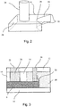
- Each electrode (one of which is shown generally as 6 in Figures 2 and 3 ) is formed on the gel supporting sheet by the printing of carbon epoxy.
- the facing sheet includes access ports 22 to enable electrodes within the cassette to be individually connected in use to an electrical circuit by way of metal connecting pins 24 extending from an interface unit, described below.
- the ports connect with bores 26 through the electrically insulating spacer to electrically insulate metal connecting pins from the gel matrix within the cassette.
- Each electrode has a smooth continuous outer surface 28 extending around the electrode.
- the electrode has two lobes 30 facing towards the opposed electrodes across the electrophoresis zone. Between the lobes, the outer surface includes a concave indentation 32 having a midpoint 34.
- the facing sheet includes an aperture 36 adjacent each electrode and overlapping with the said midpoint of the concave indentation.
- the bilobal shape of the electrodes enables the generation of a regular electrical field.
- the outer surface of the electrode which forms the concave indentation acts as a gas guiding formation, guiding gas bubbles 38, which are formed during use, to the midpoint of the concave indentation, adjacent the respective aperture.
- a path is provided for hydrogen and oxygen formed during electrolysis to egress from the cassette.
- the electrodes are typically spaced apart equally and the separation between electrodes is substantially the same as the width of the electrodes. We have found that this gives a good surface area of uniform electrical field.
- the current supplied to each discrete electrode is typically regulated by a current regulator to maintain the current within predetermined bounds. Such regulation has been found to prevent the current at any single discrete electrode from becoming too high such that short circuits may arise.
- the dimensions of the cassette will be selected depending on the intended application of the apparatus but may, for example, be 66 x 90 x 4.5 mm with a gel thickness of 2.5 mm.
- the cassette is mounted in use within an interface unit 40, which comprises a support block 42, a temperature regulation plate 44, a power supply 46 and a control unit 48.
- the support block has a base 50 and a detachable lid 52.
- the base has an aperture 54 through which the temperature regulation plate extends to contact the gel supporting sheet of a cassette retained within a cassette support 56 in use.
- the detachable lid has a central window 58 through which a mounted cassette may be viewed, four electrical circuits 60 and an electrical terminal 62 associated with each electrical circuit for connection to an external electrophoresis power supply.
- Each of the four electrical circuits extends to metal pins around the central window which, when a cassette is located within the cassette support and the lid is closed, extends through a respective access port and bore through the insulating spacer, to connect an individual electrode to the respective electrical circuit.
- each electrical circuit comprises a wired connection 64 extending from each of the electrodes through the respective metal connecting pin to a junction 66 and a wire 68 extending from the junction to the respective electrical terminal 62.
- a relay 70 switched by a switch regulator 72.
- Figure 6 illustrates electrical circuits including a separate relay for each electrode, a one or more multi-pole relays, operable to connect or disconnect a plurality of electrodes from the electrical terminal, could be provided for each group of discrete electrodes.
- relays other electronic switches, such as solid state switches, may be employed.
- the potential difference applied in use between opposed groups of discrete electrodes may be several hundred volts (for example, 400V), but the potential difference output by the switch regulator typically may be much less, for example 5V, enabling the switch regulator to readily interface with a microprocessor 74 or other controller provided within the control unit and operable to control the electrophoresis process by providing signals to the switch regulators and by controlling other functions, for example, controlling the temperature of the temperature regulation plate.
- a microprocessor 74 or other controller provided within the control unit and operable to control the electrophoresis process by providing signals to the switch regulators and by controlling other functions, for example, controlling the temperature of the temperature regulation plate.
- a cassette comprising polyacrylamide/TBE gel matrix containing urea (a temperature-dependent denaturing agent) is mounted onto the interface unit.
- urea a temperature-dependent denaturing agent
- a user sets the experimental conditions, if required, through a user interface of the control unit.
- the user will set a desired temperature, for example 4°C.
- the control unit causes the temperature regulation plate to regulate the temperature of the cassette to reach the desired temperature.
- a sample is then introduced into the gel matrix through the sample loading aperture and the user presses a button to indicate that the separation process should begin. In some applications, the sample will be introduced into the gel matrix before the temperature of the gel is set.
- each electrode is electrically isolated from all other electrodes and from the power supply by way of the relays.
- the controller signals the switch regulators associated with the electrical circuits connected with group of discrete electrodes 6a and opposed group of discrete electrodes 6b to close the respective relays which they regulate.
- a potential difference supplied by an external electrophoresis power supply is supplied to the electrodes such that each of the electrodes 6a within one group are connected to each other and to one pole of the power supply and each of the electrodes 6b within the other opposing group are connected to each other and to another pole of the power supply, thereby generating an electrical field through the electrophoresis zone in a first direction.
- Charged molecules within the sample begin to move in the first direction at a rate determined by their net charge, size and conformation.
- the electrodes within the two groups 6c, 6d which form the second set of electrodes are electrically isolated from each other and from the electrophoresis power supply. As a result, they distort the electrical field generated by the first set of electrodes less than would be the case if a single elongate electrode extended along each of the second pair edges of electrophoresis zone or if the electrodes within each group were in electrical communication with each other.
- the controller After a preset period of time, the controller signals the switch regulators to cause the respective relays to isolate each electrode, switching off the potential difference in the electrophoresis zone.
- the temperature of the temperature regulation plate is increased, for example to 37°C, and the gel support is incubated at that temperature until the gel matrix within the electrophoresis zone has reached 37°C. At this temperature, urea within the gel matrix denatures nucleic acids with the sample, separating strands of double stranded nucleic acids
- the controller After a further preset period of time, the controller signals the switch regulators associated with the electrical circuits connected with the group of discrete electrodes 6c and the opposed group of discrete electrodes 6d which together form the second set of electrodes, to close the respective relays which they regulate.
- a potential difference supplied by an external electrophoresis power supply is supplied to the electrodes such that each of the electrodes 6c within one group are connected to each other and to one pole of the power supply and each of the electrodes 6d within the other opposing group are connected to each other and to another pole of the power supply, thereby generating an electrical field through the electrophoresis zone in a second direction.
- Charged molecules within the sample begin to move in the second direction at a rate determined by their net charge, size and conformation in their denatured state.
- the electrodes within the two groups of discrete electrodes which form the first set of electrodes are electrically isolated from each other. Again, this arrangement distorts the electrical field generated by the second set of electrodes less than would be the case if a single elongate electrode extended along each of the first pair of edges of the electrophoresis zone or if the electrodes within each group were in electrical communication with each other.
- the power supply to the temperature regulation plate and the electrodes is cut and the electrophoresis procedure is completed.
- the gel matrix is removed from the gel support and incubated within a solution or buffer comprising a dye agent operable to label any nucleic acid present within the gel matrix. After labelling the gel matrix is imaged and the image is recorded for analysis.
- FIG. 7 The effect of the above electrophoresis method is shown in Figure 7 , illustrating a sample of DNA molecules separated in a first direction 76 and then a second direction 78.
- Single stranded DNA molecules (in the original sample) have been separated, by length, along the diagonal axis 80.
- Double stranded DNA molecules have been separated, by length, on the curved line 82 beneath the diagonal axis. If the sample were to include RNA-DNA hybrid molecules, they would be separated, by length, on the curved line 84 below both the diagonal axis and the curved line of the double stranded DNA molecules.
- a user can rapidly assess the proportion of single stranded DNA and double stranded DNA (or single stranded RNA and double stranded RNA or RNA-DNA hybrids) within the original sample, and the length distribution of molecules of each strandedness.
- Another cassette may be introduced into the electrophoresis apparatus and the process repeated to separate molecules within another sample. Due to the high level of automation, the process can be carried out efficiently with minimal user input.
- the electrophoresis apparatus is used to separate nucleic acid samples, for example samples of nucleic acids from 100 nucleotides to 2,000 nucleotides in length.
- the degree of separation may be varied by using gel matrices with a higher or lower percentage of polyacrylamide. For example, using a gel matrix with six percent polyacrylamide will allow molecules of a similar mass to migrate further in a given time for a given potential difference than a gel matrix with twelve percent polyacrylamide.
- the automated process controlled by the controller is carried out manually by the user.
- the voltage applied to a group of discrete electrodes is set by the user and the time the set voltage is applied to the group of discrete electrodes is controlled directly by the user. Whilst such a manual control system is user intensive, it allows the process to dynamically change upon unexpected or unwanted events. For example, the sample may run through the gel in one direction faster than expected and the running time be adjusted accordingly to compensate.
- the sample or gel further comprises a fluorescent dye operable to label the nucleic acid molecules present within the sample.
- the interface unit further comprises a camera operable to image the electrophoresis zone electrophoresis in both the first and second directions. Therefore, it is possible to observe the sample whilst electrophoresis is occurring. In this way it is possible to halt electrophoresis when sufficient molecular separation has occurred, or when the molecules to be separated are in danger of migrating out of the electrophoresis zone.
- the labelled sample within the gel may be imaged during or after electrophoresis using a scanner.
- the electrodes defining the first pair of edges of the electrophoresis zone do not extend along the full length of the first pair of edges.
- a single electrode may be provided on each of the first pair of edges located towards one side of the first pair of edges. This is sufficient for many applications as, during the first electrophoresis step, the sample remains with a linear zone of minimal breadth.
Landscapes
- Chemical & Material Sciences (AREA)
- Health & Medical Sciences (AREA)
- Life Sciences & Earth Sciences (AREA)
- Molecular Biology (AREA)
- Electrochemistry (AREA)
- Chemical Kinetics & Catalysis (AREA)
- Analytical Chemistry (AREA)
- Physics & Mathematics (AREA)
- Dispersion Chemistry (AREA)
- Biochemistry (AREA)
- General Health & Medical Sciences (AREA)
- General Physics & Mathematics (AREA)
- Immunology (AREA)
- Pathology (AREA)
- Engineering & Computer Science (AREA)
- Environmental & Geological Engineering (AREA)
- Investigating Or Analysing Biological Materials (AREA)
- Peptides Or Proteins (AREA)
- Apparatus Associated With Microorganisms And Enzymes (AREA)
Description
- The invention concerns apparatus and a method for separating a mixture of molecules using two-dimensional gel electrophoresis.
- The separation of biologically active or important molecules is a key area for biochemistry and molecular biology. One standard method for isolating or identifying such molecules is polyacrylamide-gel electrophoresis (PAGE), for example, where the molecules in question are induced to migrate through a polyacrylamide-gel matrix by an electric field. For a given magnitude of the electric field, the speed at which the molecules migrate is dependent on their mass, charge and conformation where the smaller molecules, or molecules with a high charge/mass ratio migrate at a faster rate than the larger molecules or molecules with a lower charge/mass ratio. After staining of the resultant gel with an appropriate agent able to stain the target molecules, a distribution of bands is revealed in order of molecular mass. Use of molecular markers (a mixture of standard molecules whose masses are known) running in parallel to the sample to be identified or separated allows the molecular masses to be accurately assessed.
- Electrophoresis can be performed to separate molecules by properties other than their mass by appropriate treatment of the gel matrix. For example, molecules can be separated by isoelectric focussing, whereby a pH gradient is formed across the gel matrix prior to electrophoresis and molecules are drawn to the point on the gradient where their overall charge is zero (otherwise known as their isoelectric point).
- In order to better separate molecules within a sample, it is known to carry out two-dimensional electrophoresis in which a sample is subjected first to an electric field in a first direction and then a second direction. Either the electrophoresis gel will have a property which varies parallel to the first or second direction (e.g. pH) or a treatment will be applied to molecules within the sample, for example a treatment which denatures molecules within the sample, between electrophoresis in the first direction and electrophoresis in the second direction. For example, in order to analyse the composition of a mixture of RNA and DNA molecules of a range of lengths and potentially including both single- and double-stranded molecules, a sample may be separated by electrophoresis in a first dimension, and then denatured to separate double-stranded molecules, and then separated by electrophoresis in a second dimension.
- One known way of carrying out two-dimensional gel electrophoresis is to provide a single pair of spaced apart electrodes which are positioned on opposing sides of a region of an electrophoresis gel. Electrophoresis is then carried out in a first direction. After an electrophoresis process, the gel is rotated relative to the electrodes enabling electrophoresis to then be carried out in a second direction.
- This process does, however, require manual intervention or complex automation. Accordingly, it has been proposed to provide two-dimensional gel electrophoresis apparatus having two sets of opposed electrodes in situ for carrying out electrophoresis in a first direction (between a first set of opposed electrodes) and then in a second direction (between the other set of opposed electrodes). For example,
US 2009/0107841 (Gunnarsson et al. ) discloses gel electrophoresis apparatus having two sets of electrodes, arranged such that two electric fields normal to each other can be alternatively applied to the gel without a requirement for the gel to be rotated in between. Gel can be provided in a cassette form enabling rapid separation of mixtures of molecules. - However, in known two-dimensional gel electrophoresis apparatus with two sets of opposed electrodes, each set of opposed electrodes comprises a single elongate electrode extending along one edge of the zone within which electrophoresis can occur. A problem with this arrangement is that because the electrodes are conductors which must remain at substantially the same electrical potential along their entire length, the pair of electrodes which are not in use distort the electrical field generated by a pair of electrodes which are in use, distorting the distribution of sample molecules after electrophoresis and reducing the surface area within which two-dimensional gel electrophoresis can be effectively carried out.
- Therefore, some aspects of the current invention aim to provide a two-dimensional gel electrophoresis system in which a more uniform electric field can be produced across the electrophoresis gel in both dimensions to provide a more even distribution of separated molecules and to maximise the useful area of the electrophoresis gel.
- A two-dimensional gel electrophoresis apparatus comprising groups of discrete electrodes is known from
US 5,405,519 A . - According to a first aspect of the invention there is provided two-dimensional gel electrophoresis apparatus comprising: a plurality of electrodes defining an electrophoresis zone and a gel support for retaining an electrophoresis gel in the electrophoresis zone, the electrophoresis zone having at least four edges, each of which is defined by at least one of the said plurality of electrodes, the at least four edges comprising first and second pairs of opposed edges, wherein at least one of the second pair of edges is defined by a group of discrete electrodes, characterised in that some or all of the electrodes have an outer wall with a concave formation on the side facing the opposed edge of the electrophoresis zone.
- Thus, some or all of the electrodes may have a plurality of lobes on the side facing the opposed edge of the electrophoresis zone. This provides a more even electrical field and reduces the risk of electrode burning.
- The invention extends in a second aspect to electrophoresis apparatus according to the first aspect of the invention further comprising electrophoresis gel retained in the electrophoresis zone by the gel support. The electrophoresis apparatus may take the form of a cassette having a body which comprises the gel support and retains electrophoresis gel within the electrophoresis zone.
- The invention also extends in a third aspect of the invention to a method of carrying out two-dimensional gel electrophoresis comprising the steps of: providing a plurality of electrodes which define an electrophoresis zone and providing electrophoresis gel in the electrophoresis zone, the electrophoresis zone having at least four edges, each edge defined by at least one of the said plurality of electrodes, the at least four edges comprising first and second pairs of opposed edges, wherein at least one of the second pair of edges is defined by a group of discrete electrodes and some or all of the electrodes have an outer wall with a generally concave formation on the side facing the opposed edge of the electrophoresis zone; and applying a potential difference between the electrodes defining the first pair of opposed edges, to generate an electrical field in a first direction across the electrophoresis zone, whilst the electrodes within the or each group of discrete electrodes which define the at least one of the second pair of edges are electrically isolated from each other.
- Typically, each of the second pairs of edges are defined by a group of discrete electrodes. Typically, the electrodes within the groups of discrete electrodes which define each of the second pairs of edges are electrically isolated from each other whilst a potential difference is applied between the electrodes defining the first pair of edges to generate an electrical field across the electrophoresis zone.
- By defining the at least one (and typically both) of the second pair of edges using a group of discrete electrodes and carrying out electrophoresis by applying a potential difference to the electrodes defining the first pair of opposed edges to generate an electrical field across the electrophoresis zone whilst at least two (and typically each) of the electrodes within the (or typically each) group of discrete electrodes which define at least one (and typically both) of the second pair of opposed edges are electrically isolated from each other, distortion of the electrical field generated in the first direction by the electrodes defining the second pair of opposed edges is reduced. This contrasts with known electrophoresis apparatus in which each of the second pair of edges is defined by a single elongate electrode, short circuiting the electric field generated by the electrodes, defining the first pair of edges, and bending electrical field lines.
- Thus, a more uniform electrical field can be generated in the first direction, providing a more controlled and precisely defined separation of molecules. Furthermore, a larger portion of the electrophoresis zone defined by the electrodes may be used.
- Preferably, at least one (and typically both) of the first pair of edges is defined by a group of discrete electrodes. In this case, the method typically comprises the step of applying a potential difference between the electrodes defining the second pair of opposed edges, to generate an electrical field in a second direction across the electrophoresis zone, whilst at least two (and typically each) electrode within the (or typically each) group of discrete electrodes which define the at least one (and typically both) of the first pair of edges are electrically isolated from each other.
- The first and second directions are at an angle to each other. However, the first and second directions are typically orthogonal to each other. In this case, the electrophoresis zone is typically rectangular, for example square or oblong.
- The method typically comprises the step of treating the sample within the electrophoresis zone after the application of an electrical field in the first direction and before the application of an electrical field in the second direction, so that molecules within the sample respond differently to the electrical field in the second direction. Gel within the electrophoresis zone may comprise an activatable denaturing agent. The activatable denaturing agent may be operable to separate double stranded nucleic acid molecules, or a mixture of proteins. The activatable denaturing agent may be temperature activatable, for example, the activatable denaturing agent may be urea. Thus, the treatment may be heating. However, the activatable denaturing agent may be activatable by another means, for example light.
- Preferably, the discrete electrodes within the or each group of discrete electrodes are electrically isolatable from one another. Typically each of the plurality of electrodes within a group has a respective electrical contact, in direct electrical communication with only one said electrode, for connection to isolating means thereby enabling the electrodes within each group to be isolatable from each other or connectable to each other by way of isolating means.
- Preferably, the isolating means is operable in an isolating mode, in which discrete electrodes within a group are isolated, and in an operational mode, in which the discrete electrodes within a group are electrically connected to one or more electrical terminals.
- Isolating means may be provided externally to the electrophoresis apparatus. For example, the electrophoresis apparatus may be a cassette having a separate electrical contact associated with each electrode and in direct electrical communication with only one said electrode. Some or all said electrical contacts may be a surface of an electrode. During use, the electrical contacts may be in electrical communication with external electrical circuits associated with each group of discrete electrodes. Said electrical circuits may comprise isolating means for each electrode within the groups of discrete electrodes.
- Alternatively, the electrophoresis apparatus may comprise isolating means. For example, the electrophoresis apparatus may comprise an electrical terminal for connection to a pole of a power supply in direct electrical communication with all electrodes within each individual group of discrete electrodes, and isolating means between said electrical terminal and individual electrodes within each group of discrete electrodes.
- The isolating means may comprise an electrical circuit extending between the electrodes in a group of discrete electrodes and an electrical terminal, the electrical circuit operable between an isolating mode and an operational mode. A said electrical circuit is typically provided for each group of discrete electrodes.
- Typically, in the isolating mode the electrodes in the group are typically substantially electrically isolated from each other and from any electrical terminal. In the operational mode the electrodes in the group are electrically connected to an electrical terminal. Several or all of the electrodes may in that case be connected to the same electrical terminal. Each electrode in the group may adopt the same potential in the operational mode, for example, each electrode in the group may be in direct electrical communication in the operational mode. However, it may be that the electrical circuit associated with the group of electrodes determines that at least two of the electrodes within the group of electrodes have different potentials in use. The electrical circuit may be selected to determine the relative potentials of each electrode in the group in the operational mode to apply a uniform electric field to the electrophoresis zone.
- The isolating means typically comprises one or more switches, for example one or more relays or solid state switches. The method may comprise controlling one or more switches to electrically isolate electrodes within a group of discrete electrodes from each other.
- The electrical terminal may be a connection to an internal power supply, such as a battery, but is typically a connection to an external power supply. The electrical circuit may be adapted to switch from the isolating mode to the operational mode when a potential difference is applied between two electrical terminals, each of which is for providing an electrical potential to opposed groups of discrete electrodes.
- The electrophoresis apparatus may be connectable to an external power supply and external isolating means. For example, the electrophoresis apparatus may comprise a cassette having a separate electrical terminal in electric communication with each electrode, or a separate aperture for receiving an external electrical terminal, such as a connecting pin, to form an electrical connection with each electrode.
- The gel support may comprise a body defining a gel retaining volume therein. The electrophoresis apparatus may be in the form of a cassette having a body defining a gel retaining volume therein. The gel support may comprise a tray defining a gel retaining volume. Electrophoresis gel may be provided within the gel retaining volume.
- Typically, the gel support comprises a gel supporting sheet. Electrophoresis gel is typically retained as a sheet on the gel supporting sheet. The gel support may further comprise a facing sheet such that electrophoresis gel may be retained between the gel supporting sheet and the facing sheet. The gel supporting sheet is typically planar. The facing sheet is typically planar.
- The electrodes may be formed on a gel facing surface of the gel support, for example, on the gel facing surface of the gel supporting sheet. The electrodes may be electrodes formed by printing. The electrodes, or groups of discrete electrodes, typically comprise carbon epoxy, but may, for example, comprise silver epoxy or silver paste, platinum paste or another metal or conducting oxide. The facing sheet may comprise access ports having electrical conductors extending therethrough for providing electrical connections to the electrodes.
- The gel support may further comprise an insulating spacer around the periphery of the gel support such that at least part of the discrete electrodes extend into or beneath the insulating spacer.
- The gel support may comprise one or more apertures to enable gas produced during electrophoresis to egress from the gel support. Where the gel support encloses the electrophoresis gel, the one or more apertures preferably enable gas produced during electrophoresis to egress from the electrophoresis apparatus.
- For example, the gel support may comprise one or more apertures, each of which is associated with a said electrode, to enable gas produced by the respective electrode to egress from the gel support. The gel supporting sheet or, more typically, the facing sheet, may comprise one or more said apertures. This is a significant safety feature, minimising the build up of hydrogen and oxygen.
- Some or all of the electrodes may comprise a gas guiding formation operable to direct generated gas towards a said aperture. For example, the electrodes may have an outer wall having a concave indentation and the respective aperture may be located adjacent to the concave indentation so that a portion of the outer wall forming the concave indentation functions as a gas guiding formation.
- Preferably, some or all of the electrodes comprise a smooth continuous surface such that there are no sharp corners or vertices to further reduce the risk of electrode burning.
- Preferably, discrete electrodes in a group of discrete electrodes are arranged in a line defining part of an edge of the electrophoresis zone. Preferably, the ratio of the discrete electrode width parallel to the respective edge (w) to the sum of said width and the space (s) between discrete electrodes,

- The current supplied to individual discrete electrodes may be regulated by a current regulator such that the current at any one discrete electrode is maintained within predetermined bounds to prevent the discrete electrodes short circuiting.
- Each group of discrete electrodes preferably comprises three or more discrete electrodes. The opposed groups of discrete electrodes defining the second pair of edges preferably each comprise four or more discrete electrodes. The provision of a relatively large number of electrodes enables relatively even electrical fields to be generated.
- The electrophoresis gel may be polyacrylamide with the common buffer Tris Borate Ethylenediaminetetraacetic acid, or EDTA (TBE) but may be other gel matrices and buffers used in electrophoresis such as agarose and Tris Acetate EDTA (TAE). Electrophoresis gel may be pre-cast within the gel support, for example when the electrophoresis apparatus is provided as a cassette. Alternatively, electrophoresis gel may be cast within the gel support just prior to use, or a pre-cast gel placed within the gel support prior to use.
- Preferably, the apparatus does not comprise an external buffer reservoir, as normally required in conventional gel electrophoresis.
- The electrophoresis gel may comprise a temperature activated denaturing agent, such as urea. The electrophoresis gel may further comprise a labelling agent operable to label sample molecules introduced to the electrophoresis gel such that after electrophoresis the sample molecule are detectable, for example visually observable. The labelling agent is typically a fluorescent species such as Ribo Green, SYBR Green or LC Green, but may be a non-fluorescent dye or a radioactive species.
- An example embodiment of the present invention will now be illustrated with reference to the following Figures in which:
-
Figure 1 is a plan view of a two-dimensional gel electrophoresis cassette; -
Figure 2 is a perspective view of a single discrete electrode; -
Figure 3 is a side view of a discrete electrode in situ within the gel support; -
Figure 4 is a plan view of a two-dimensional gel electrophoresis cassette mounted on an interface unit; -
Figure 5 is a plan view of an electrical interface unit base 5(a) and detachable lid 5(b); -
Figure 6 is (a) an electrical circuit for isolation of one group of discrete electrodes and (b) an array of relay isolation switches; and -
Figure 7 is a schematic diagram of the separation of a sample of nucleic acid, by the two-dimensional gel electrophoresis process of the present invention. - With reference to
Figures 1 to 6 , there is provided two-dimensional electrophoresis apparatus comprising acassette 2 having abody 4 functioning as the gel support. The gel support retains a gel matrix formed of electrophoresis gel. The cassette includes four groups ofdiscrete electrodes electrophoresis zone 8, within which electrical fields can be created between opposed groups of discrete electrodes to carry out electrophoresis. - Each of the four groups of discrete electrodes comprises a plurality of discrete electrodes. A first set of
electrodes electrodes - With references to
Figures 2 and 3 , the gel support comprises agel supporting sheet 10 and a facingsheet 12, which are opposed and which together retain gel matrix. Substantially enclosing the electrophoresis gel facilitates polymerisation and reduces evaporation. The gel supporting sheet may be underneath the gel in use, although in some embodiments the gel may be oriented vertically in use and the gel supporting sheet and facing sheet may each provide equivalent support to gel matrix. The gel support further includes an electrically insulatingspacer 14 around the periphery of the gel support. Part of each of the discrete electrodes extends between the electrically insulating spacer and the gel supporting sheet. - The facing sheet comprises a
sample loading aperture 16, through which a sample can be introduced to agel matrix 18 retained by the gel support within the electrophoresis zone. The gel matrix extends beyond the electrophoresis zone such that the discrete electrode elements are in electrical contact with the ions within the gel matrix. The facing sheet also includes two pouringapertures 20 which are provided to enable gel matrix to be poured into the gel support. In this example, the gel matrix will typically be preloaded into the cassette, in which case the pouring apertures will have been used during manufacture although, in alternative embodiments, apparatus may be provided without gel matrix present, in which case the pouring apertures are employed to enable gel matrix to be loaded. In further alternative embodiments, a cassette may have been preformed without pouring apertures by providing an open gel support which is subsequently sealed during manufacture. - Each electrode (one of which is shown generally as 6 in
Figures 2 and 3 ) is formed on the gel supporting sheet by the printing of carbon epoxy. The facing sheet includesaccess ports 22 to enable electrodes within the cassette to be individually connected in use to an electrical circuit by way ofmetal connecting pins 24 extending from an interface unit, described below. The ports connect withbores 26 through the electrically insulating spacer to electrically insulate metal connecting pins from the gel matrix within the cassette. - Each electrode has a smooth continuous
outer surface 28 extending around the electrode. The electrode has twolobes 30 facing towards the opposed electrodes across the electrophoresis zone. Between the lobes, the outer surface includes aconcave indentation 32 having amidpoint 34. The facing sheet includes anaperture 36 adjacent each electrode and overlapping with the said midpoint of the concave indentation. - This configuration has two purposes. Firstly, the bilobal shape of the electrodes enables the generation of a regular electrical field. Secondly, the outer surface of the electrode which forms the concave indentation acts as a gas guiding formation, guiding gas bubbles 38, which are formed during use, to the midpoint of the concave indentation, adjacent the respective aperture. Thus, a path is provided for hydrogen and oxygen formed during electrolysis to egress from the cassette.
- The electrodes are typically spaced apart equally and the separation between electrodes is substantially the same as the width of the electrodes. We have found that this gives a good surface area of uniform electrical field.
- The current supplied to each discrete electrode is typically regulated by a current regulator to maintain the current within predetermined bounds. Such regulation has been found to prevent the current at any single discrete electrode from becoming too high such that short circuits may arise.
- The dimensions of the cassette will be selected depending on the intended application of the apparatus but may, for example, be 66 x 90 x 4.5 mm with a gel thickness of 2.5 mm.
- The cassette is mounted in use within an
interface unit 40, which comprises asupport block 42, atemperature regulation plate 44, apower supply 46 and acontrol unit 48. The support block has abase 50 and adetachable lid 52. The base has anaperture 54 through which the temperature regulation plate extends to contact the gel supporting sheet of a cassette retained within acassette support 56 in use. The detachable lid has acentral window 58 through which a mounted cassette may be viewed, fourelectrical circuits 60 and anelectrical terminal 62 associated with each electrical circuit for connection to an external electrophoresis power supply. Each of the four electrical circuits extends to metal pins around the central window which, when a cassette is located within the cassette support and the lid is closed, extends through a respective access port and bore through the insulating spacer, to connect an individual electrode to the respective electrical circuit. - When the cassette is mounted within the interface unit in this way, the discrete electrodes within a group of discrete electrodes (6a, 6b, 6c or 6d) are connected by way of an electrical circuit which extends between each electrode within the group and the respective electrical terminal for attachment to a pole of an electrophoresis power supply. Each electrical circuit comprises a
wired connection 64 extending from each of the electrodes through the respective metal connecting pin to ajunction 66 and awire 68 extending from the junction to the respectiveelectrical terminal 62. Between each electrode and the junction is located arelay 70 switched by aswitch regulator 72. AlthoughFigure 6 illustrates electrical circuits including a separate relay for each electrode, a one or more multi-pole relays, operable to connect or disconnect a plurality of electrodes from the electrical terminal, could be provided for each group of discrete electrodes. Instead of relays, other electronic switches, such as solid state switches, may be employed. - The potential difference applied in use between opposed groups of discrete electrodes may be several hundred volts (for example, 400V), but the potential difference output by the switch regulator typically may be much less, for example 5V, enabling the switch regulator to readily interface with a
microprocessor 74 or other controller provided within the control unit and operable to control the electrophoresis process by providing signals to the switch regulators and by controlling other functions, for example, controlling the temperature of the temperature regulation plate. - In use, a cassette comprising polyacrylamide/TBE gel matrix containing urea (a temperature-dependent denaturing agent) is mounted onto the interface unit. When the lid is closed, the metal pins extend into the cassette to contact the electrodes within the cassette.
- A user sets the experimental conditions, if required, through a user interface of the control unit. Typically, the user will set a desired temperature, for example 4°C. The control unit causes the temperature regulation plate to regulate the temperature of the cassette to reach the desired temperature. A sample is then introduced into the gel matrix through the sample loading aperture and the user presses a button to indicate that the separation process should begin. In some applications, the sample will be introduced into the gel matrix before the temperature of the gel is set.
- Before separation commences, each electrode is electrically isolated from all other electrodes and from the power supply by way of the relays. To commence separation, the controller signals the switch regulators associated with the electrical circuits connected with group of
discrete electrodes 6a and opposed group ofdiscrete electrodes 6b to close the respective relays which they regulate. A potential difference supplied by an external electrophoresis power supply is supplied to the electrodes such that each of theelectrodes 6a within one group are connected to each other and to one pole of the power supply and each of theelectrodes 6b within the other opposing group are connected to each other and to another pole of the power supply, thereby generating an electrical field through the electrophoresis zone in a first direction. Charged molecules within the sample begin to move in the first direction at a rate determined by their net charge, size and conformation. - Whilst electrophoresis occurs in the first direction, the electrodes within the two
groups - After a preset period of time, the controller signals the switch regulators to cause the respective relays to isolate each electrode, switching off the potential difference in the electrophoresis zone.
- Under the control of the controller, the temperature of the temperature regulation plate is increased, for example to 37°C, and the gel support is incubated at that temperature until the gel matrix within the electrophoresis zone has reached 37°C. At this temperature, urea within the gel matrix denatures nucleic acids with the sample, separating strands of double stranded nucleic acids
- After a further preset period of time, the controller signals the switch regulators associated with the electrical circuits connected with the group of
discrete electrodes 6c and the opposed group ofdiscrete electrodes 6d which together form the second set of electrodes, to close the respective relays which they regulate. A potential difference supplied by an external electrophoresis power supply is supplied to the electrodes such that each of theelectrodes 6c within one group are connected to each other and to one pole of the power supply and each of theelectrodes 6d within the other opposing group are connected to each other and to another pole of the power supply, thereby generating an electrical field through the electrophoresis zone in a second direction. Charged molecules within the sample begin to move in the second direction at a rate determined by their net charge, size and conformation in their denatured state. - Whilst an electric field is applied in the second direction the electrodes within the two groups of discrete electrodes which form the first set of electrodes are electrically isolated from each other. Again, this arrangement distorts the electrical field generated by the second set of electrodes less than would be the case if a single elongate electrode extended along each of the first pair of edges of the electrophoresis zone or if the electrodes within each group were in electrical communication with each other.
- After a preset period of time, the power supply to the temperature regulation plate and the electrodes is cut and the electrophoresis procedure is completed. The gel matrix is removed from the gel support and incubated within a solution or buffer comprising a dye agent operable to label any nucleic acid present within the gel matrix. After labelling the gel matrix is imaged and the image is recorded for analysis.
- The effect of the above electrophoresis method is shown in
Figure 7 , illustrating a sample of DNA molecules separated in afirst direction 76 and then asecond direction 78. Single stranded DNA molecules (in the original sample) have been separated, by length, along thediagonal axis 80. Double stranded DNA molecules have been separated, by length, on thecurved line 82 beneath the diagonal axis. If the sample were to include RNA-DNA hybrid molecules, they would be separated, by length, on thecurved line 84 below both the diagonal axis and the curved line of the double stranded DNA molecules. Thus, a user can rapidly assess the proportion of single stranded DNA and double stranded DNA (or single stranded RNA and double stranded RNA or RNA-DNA hybrids) within the original sample, and the length distribution of molecules of each strandedness. - Another cassette may be introduced into the electrophoresis apparatus and the process repeated to separate molecules within another sample. Due to the high level of automation, the process can be carried out efficiently with minimal user input.
- In a typical application, the electrophoresis apparatus is used to separate nucleic acid samples, for example samples of nucleic acids from 100 nucleotides to 2,000 nucleotides in length. However, for samples of molecules of similar size ranges, the degree of separation may be varied by using gel matrices with a higher or lower percentage of polyacrylamide. For example, using a gel matrix with six percent polyacrylamide will allow molecules of a similar mass to migrate further in a given time for a given potential difference than a gel matrix with twelve percent polyacrylamide.
- In an alternative embodiment, the automated process controlled by the controller is carried out manually by the user. The voltage applied to a group of discrete electrodes is set by the user and the time the set voltage is applied to the group of discrete electrodes is controlled directly by the user. Whilst such a manual control system is user intensive, it allows the process to dynamically change upon unexpected or unwanted events. For example, the sample may run through the gel in one direction faster than expected and the running time be adjusted accordingly to compensate.
- In an alternative embodiment the sample or gel further comprises a fluorescent dye operable to label the nucleic acid molecules present within the sample. In this embodiment the interface unit further comprises a camera operable to image the electrophoresis zone electrophoresis in both the first and second directions. Therefore, it is possible to observe the sample whilst electrophoresis is occurring. In this way it is possible to halt electrophoresis when sufficient molecular separation has occurred, or when the molecules to be separated are in danger of migrating out of the electrophoresis zone.
- In an alternative embodiment, the labelled sample within the gel may be imaged during or after electrophoresis using a scanner.
- In an alternative embodiment the electrodes defining the first pair of edges of the electrophoresis zone do not extend along the full length of the first pair of edges. For example, a single electrode may be provided on each of the first pair of edges located towards one side of the first pair of edges. This is sufficient for many applications as, during the first electrophoresis step, the sample remains with a linear zone of minimal breadth.
- Further variations and modifications may be made within the scope of the appended claims.
Claims (15)
- Two-dimensional gel electrophoresis apparatus (2) comprising: a plurality of electrodes (6a, 6b, 6c, 6d) defining an electrophoresis zone (8) and a gel support (4) for retaining an electrophoresis gel in the electrophoresis zone, the electrophoresis zone having at least four edges, each of which is defined by at least one of the said plurality of electrodes, the at least four edges comprising first and second pairs of opposed edges, wherein at least one of the second pair of edges is defined by a group of discrete electrodes, characterised in that some or all of the electrodes have an outer wall (28) with a generally concave formation (32) on the side facing the opposed edge of the electrophoresis zone.
- Two-dimensional gel electrophoresis apparatus according to claim 1, wherein both of the second pair of edges and/or one or both of the first pair of edges are defined by respective groups of discrete electrodes.
- Two-dimensional gel electrophoresis apparatus according to any one preceding claim, further comprising isolating means (70) operable in an isolating mode, in which discrete electrodes within a group are isolated, and in an operational mode, in which the discrete electrodes within a group are electrically connected to one or more electrical terminals (62).
- Two-dimensional gel electrophoresis apparatus according to claim 3, wherein the isolating means comprises an electrical circuit (60, 64, 66, 68, 70) extending between the electrodes in a group of discrete electrodes and an electrical terminal, the electrical circuit operable between an isolating mode and an operational mode.
- Two-dimensional gel electrophoresis apparatus according to claim 4, wherein the electrical circuit associated with the group of electrodes determines that at least two of the electrodes within the group of electrodes have different potentials in use.
- Two-dimensional gel electrophoresis apparatus according to any one preceding claim, wherein the gel support comprises one or more apertures (36), each of which is associated with a said electrode, to enable gas produced by the respective electrode to egress from the gel support.
- Two-dimensional gel electrophoresis apparatus according to claim 6, wherein some or all of the electrodes comprise a gas guiding formation (32) operable to direct generated gas towards a said aperture (36) associated with the respective electrode.
- Two-dimensional gel electrophoresis apparatus according to any one preceding claim, wherein discrete electrodes in a group of discrete electrodes are arranged in a line defining part of an edge of the electrophoresis zone and wherein the ratio of the discrete electrode width parallel to the respective edge to the sum of said width and the space between discrete electrodes, is between 0.3 and 0.7.
- Two-dimensional gel electrophoresis apparatus according to any one preceding claim further comprising electrophoresis gel (18) retained in the electrophoresis zone by the gel support.
- A method of carrying out two-dimensional gel electrophoresis comprising the steps of: providing a plurality of electrodes (6a, 6b, 6c, 6d) which define an electrophoresis zone (8) and providing electrophoresis gel (18) in the electrophoresis zone, the electrophoresis zone having at least four edges, each edge defined by at least one of the said plurality of electrodes, the at least four edges comprising first and second pairs of opposed edges, wherein at least one of the second pair of edges is defined by a group of discrete electrodes and some or all of the electrodes have an outer wall (28) with a generally concave formation (32) on the side facing the opposed edge of the electrophoresis zone; and applying a potential difference between the electrodes defining the first pair of opposed edges, to generate an electrical field in a first direction across the electrophoresis zone, whilst the electrodes within the or each group of discrete electrodes which define the at least one of the second pair of edges are electrically isolated from each other.
- A method according to claim 10, wherein both of the second pair of edges are defined by respective groups of discrete electrodes and a potential difference is applied between the group of discrete electrodes which defines one of the first pair of opposed edges and the group of discrete electrodes which defined the other of the first pair of opposed edges to generate an electrical field in a first direction across the electrophoresis zone, whilst the electrodes within the or each group of discrete electrodes which define the at least one of the second pair of edges are electrically isolated from each other, and wherein one or both of the first pair of edges are defined by respective groups of discrete electrodes, and wherein the method comprises the step of applying a potential difference between the electrodes defining the second pair of opposed edges to generate an electrical field in a second direction across the electrophoresis zone, whilst the electrodes within the or each group of discrete electrodes which define the at least one of the first pair of edges are electrically isolated from each other.
- A method according to claim 10 or claim 11, wherein an electrical circuit (60, 64, 66, 68, 70) extends between the electrodes in a group and an electrical terminal, and the method comprises operating the electrical circuit between an isolating mode where the electrodes in the group are electrically isolated from each other and an operational mode in which the electrodes in the group are electrically connected to each other and to the electrical terminal (62) and/or are each electrically connected to the electrical terminal.
- A method according to any one of claims 10 to 12, wherein gas generated at some or all of the electrodes during use egresses from the gel support through an aperture (36) associated with each respective electrode.
- A method according to any one of claims 10 to 13, wherein the electrophoresis gel comprises an activatable denaturing agent and the method comprises the step of activating the activatable denaturing agent after carrying out electrophoresis in a first direction and before carrying out electrophoresis in a second direction.
- A method according to claim 14, comprising separating a mixture of single stranded and double stranded nucleic acids, or a mixture of proteins
Applications Claiming Priority (2)
| Application Number | Priority Date | Filing Date | Title |
|---|---|---|---|
| GBGB1102385.0A GB201102385D0 (en) | 2011-02-10 | 2011-02-10 | Two-dimensional gel electrophoresis apparatus and method |
| PCT/GB2012/050295 WO2012107774A1 (en) | 2011-02-10 | 2012-02-10 | Two-dimensional gel electrophoresis apparatus and method |
Publications (2)
| Publication Number | Publication Date |
|---|---|
| EP2673627A1 EP2673627A1 (en) | 2013-12-18 |
| EP2673627B1 true EP2673627B1 (en) | 2017-08-23 |
Family
ID=43859256
Family Applications (1)
| Application Number | Title | Priority Date | Filing Date |
|---|---|---|---|
| EP12712143.2A Not-in-force EP2673627B1 (en) | 2011-02-10 | 2012-02-10 | Two-dimensional gel electrophoresis apparatus and method |
Country Status (5)
| Country | Link |
|---|---|
| US (2) | US20140054172A1 (en) |
| EP (1) | EP2673627B1 (en) |
| AU (1) | AU2012215131A1 (en) |
| GB (1) | GB201102385D0 (en) |
| WO (1) | WO2012107774A1 (en) |
Families Citing this family (11)
| Publication number | Priority date | Publication date | Assignee | Title |
|---|---|---|---|---|
| WO2013158686A1 (en) | 2012-04-16 | 2013-10-24 | Biological Dynamics, Inc. | Nucleic acid sample preparation |
| US8932815B2 (en) | 2012-04-16 | 2015-01-13 | Biological Dynamics, Inc. | Nucleic acid sample preparation |
| CN106459966A (en) * | 2014-04-08 | 2017-02-22 | 生物动力学公司 | Improved devices for separation of biological materials |
| WO2017165852A1 (en) | 2016-03-24 | 2017-09-28 | Biological Dynamics, Inc. | Disposable fluidic cartridge and components |
| IL270445B2 (en) | 2017-05-08 | 2024-06-01 | Biological dynamics inc | Methods and systems for processing information on tested material |
| EP3652314B1 (en) | 2017-07-12 | 2023-08-23 | Illumina, Inc. | Nucleic acid extraction materials and methods |
| WO2019126388A1 (en) | 2017-12-19 | 2019-06-27 | Biological Dynamics, Inc. | Methods and devices for detection of multiple analytes from a biological sample |
| US11883833B2 (en) | 2018-04-02 | 2024-01-30 | Biological Dynamics, Inc. | Dielectric materials |
| JP6903617B2 (en) * | 2018-09-19 | 2021-07-14 | 株式会社東芝 | How to determine the molecular probe |
| US20210109615A1 (en) * | 2019-10-14 | 2021-04-15 | RET Equipment Inc. | Resistive pressure sensor device system |
| US20220397550A1 (en) * | 2019-11-12 | 2022-12-15 | T-Mac Co., Ltd. | Horizontal electrophoresis apparatus |
Family Cites Families (44)
| Publication number | Priority date | Publication date | Assignee | Title |
|---|---|---|---|---|
| US4148703A (en) * | 1976-02-11 | 1979-04-10 | Morton Weintraub | Method of electrophoretic purification of enzymes and peptides by means of an adjustable, specialized, geometrically located electrode system |
| US4861448A (en) * | 1982-11-18 | 1989-08-29 | The Trustees Of Columbia University In The City Of New York | Electrophoretic methods employing gel inserts |
| SE452853B (en) | 1986-02-13 | 1987-12-21 | Pharmacia Ab | WAY TO SUPPLY BUFFER SOLUTIONS FOR ELECTROPHORETIC SEPARATION |
| US5549796A (en) * | 1986-08-14 | 1996-08-27 | The Board Of Trustees Of The Leland Stanford Junior University | Electrophoresis using contour-clamped electric fields |
| US4892639A (en) | 1987-07-17 | 1990-01-09 | Helena Laboratories Corporation | Electrophoresis plate and method of making same |
| FR2620230B1 (en) * | 1987-09-07 | 1990-02-23 | Ari Sa | METHOD AND DEVICE FOR THE ELECTROPHORESIS OF LARGE-DIMENSIONAL MACROMOLECULES |
| US5084157A (en) * | 1988-03-21 | 1992-01-28 | California Institute Of Technology | Gel electrophoresis using time dependent contour controlled electric fields |
| JPH02176457A (en) * | 1988-09-15 | 1990-07-09 | Carnegie Inst Of Washington | Pulse oriented electrophoresis |
| US4911817A (en) * | 1988-10-20 | 1990-03-27 | Eastman Kodak Company | Electrophoresis apparatus |
| US5045164A (en) | 1990-05-23 | 1991-09-03 | Helena Laboratories Corporation | Electrophoresis plate for diverting generated fluid |
| US5209831A (en) | 1991-06-14 | 1993-05-11 | Macconnell William P | Bufferless electrophoresis system and method |
| GB9305052D0 (en) | 1993-03-12 | 1993-04-28 | Univ Reading The | Gel electrophoresis apparatus |
| US6379516B1 (en) | 1995-04-26 | 2002-04-30 | Ethrog Biotechnology Ltd. | Apparatus and method for electrophoresis |
| US5582702A (en) | 1995-04-26 | 1996-12-10 | Ethrog Biotechnology Ltd. | Apparatus and method for electrophoresis |
| US5702898A (en) | 1995-06-06 | 1997-12-30 | The Trustees Of Columbia University In The City Of New York | Procedure for normalization of cDNA libraries |
| SE9703578D0 (en) | 1997-10-01 | 1997-10-01 | Pharmacia Biotech Ab | Cassette for electrophoresis system |
| DE19849278C1 (en) | 1998-10-15 | 2000-07-06 | Atotech Deutschland Gmbh | Method and device for the electrodialytic regeneration of an electroless plating bath |
| US6165337A (en) | 1998-12-23 | 2000-12-26 | Shelton Scientific Manufacturing, Inc. | Semi-dry electrophoresis apparatus and method |
| US6682641B1 (en) | 1999-04-26 | 2004-01-27 | Mj Research, Inc. | Electrophoresis assembly and method of casting electrophoresis gels |
| JP2003500662A (en) | 1999-05-25 | 2003-01-07 | ディジタル・ジーン・テクノロジーズ・インコーポレーテッド | Method and system for amplitude normalization and data peak selection |
| DE19926985B4 (en) | 1999-06-14 | 2004-12-02 | Richard Dr. Reinhardt | Method and device for gel electrophoresis |
| US6379519B1 (en) | 1999-09-01 | 2002-04-30 | Mirador Dna Design Inc. | Disposable thermoformed electrophoresis cassette |
| US20020096431A1 (en) | 1999-09-01 | 2002-07-25 | Pierre Sevigny | Apparatus for the manufacture of a disposable electrophoresis cassette and method thereof |
| US6569306B1 (en) | 2000-04-10 | 2003-05-27 | Amersham Pharmacia Biotech, Inc. | Cassette for gel electrophoresis having solid buffer reservoirs |
| US6982143B1 (en) | 2000-06-20 | 2006-01-03 | The Regents Of The University Of California | Normalizing and amplifying RNA |
| US6544741B1 (en) | 2000-07-12 | 2003-04-08 | Quark Biotech, Inc. | Sequence specific and sequence non-specific methods and materials for cDNA normalization and subtraction |
| DE60124363T2 (en) | 2000-08-25 | 2007-09-06 | Riken, Wako | Method for the production of standardized and / or subtracted cDNA |
| US6562213B1 (en) | 2000-08-30 | 2003-05-13 | Ethrog Biotechnology Ltd. | Electrophoresis apparatus for simultaneous loading of multiple samples |
| AU2001286929A1 (en) | 2000-09-01 | 2002-03-13 | Board Of Regents, The University Of Texas System | Compositions and methods for the generation of single stranded cdna microarrays with accurate universal quantitation reference |
| CA2327527A1 (en) | 2000-12-27 | 2002-06-27 | Geneka Biotechnologie Inc. | Method for the normalization of the relative fluorescence intensities of two rna samples in hybridization arrays |
| CA2390426A1 (en) | 2000-12-27 | 2002-07-04 | Geneka Biotechnology Inc. | Method for normalizing the relative intensities of detection signals in hybridization arrays |
| CA2443978A1 (en) | 2001-04-17 | 2002-10-24 | Nextgen Sciences Ltd. | Electrophoretic separation system |
| US20030032014A1 (en) | 2001-05-23 | 2003-02-13 | Chia-Lin Wei | Colony array-based cDNA library normalization by hybridizations of complex RNA probes and gene specific probes |
| CU22855A1 (en) * | 2001-06-08 | 2003-05-26 | Cnic Ct Nac Investigaciones | CIRCUIT TO IMPOSE THE VOLTAGES ON THE ELECTRODES OF THE CHEF SYSTEMS OF ELECTROPHORESIS OF PULSING FIELDS |
| AUPR800701A0 (en) | 2001-09-28 | 2001-10-25 | Proteome Systems Ltd | Cassette for electrophoresis |
| US7306912B2 (en) * | 2002-02-25 | 2007-12-11 | Lifeind Ehf. | Method for two-dimensional conformation-dependent separation of non-circular nucleic acids |
| US6905585B2 (en) | 2002-09-11 | 2005-06-14 | Temple University Of The Commonwealth System Of Higher Education | Automated system for high-throughput electrophoretic separations |
| US7250100B2 (en) | 2003-06-17 | 2007-07-31 | Duke University | Two dimensional electrophoresis cassette |
| JP4424938B2 (en) | 2003-08-19 | 2010-03-03 | タイテック株式会社 | Microgel cassette for electrophoresis |
| ATE498682T1 (en) | 2004-09-02 | 2011-03-15 | Lifeind Ehf | TWO-DIMENSIONAL STRAND SHAPE AND LENGTH-DEPENDENT SEPARATION OF NUCLEIC ACID FRAGMENTS |
| US20060228721A1 (en) | 2005-04-12 | 2006-10-12 | Leamon John H | Methods for determining sequence variants using ultra-deep sequencing |
| EP1877576B1 (en) | 2005-04-12 | 2013-01-23 | 454 Life Sciences Corporation | Methods for determining sequence variants using ultra-deep sequencing |
| EP1804058A1 (en) | 2005-12-28 | 2007-07-04 | Roche Diagnostics GmbH | Integrated two-dimensional gel electrophoresis |
| US20080318233A1 (en) | 2007-03-30 | 2008-12-25 | Glenn Travis C | Source tagging and normalization of DNA for parallel DNA sequencing, and direct measurement of mutation rates using the same |
-
2011
- 2011-02-10 GB GBGB1102385.0A patent/GB201102385D0/en not_active Ceased
-
2012
- 2012-02-10 US US13/984,616 patent/US20140054172A1/en not_active Abandoned
- 2012-02-10 WO PCT/GB2012/050295 patent/WO2012107774A1/en not_active Ceased
- 2012-02-10 EP EP12712143.2A patent/EP2673627B1/en not_active Not-in-force
- 2012-02-10 AU AU2012215131A patent/AU2012215131A1/en not_active Abandoned
-
2015
- 2015-12-16 US US14/971,216 patent/US9753010B2/en not_active Expired - Fee Related
Also Published As
| Publication number | Publication date |
|---|---|
| US9753010B2 (en) | 2017-09-05 |
| US20140054172A1 (en) | 2014-02-27 |
| EP2673627A1 (en) | 2013-12-18 |
| AU2012215131A1 (en) | 2013-09-26 |
| GB201102385D0 (en) | 2011-03-30 |
| WO2012107774A1 (en) | 2012-08-16 |
| US20160178575A1 (en) | 2016-06-23 |
Similar Documents
| Publication | Publication Date | Title |
|---|---|---|
| US9753010B2 (en) | Two-dimensional gel electrophoresis apparatus and method | |
| EP0313293B1 (en) | Method and apparatus for use in biological testing | |
| EP1486783B1 (en) | Apparatus and method for electrophoresis | |
| US6379516B1 (en) | Apparatus and method for electrophoresis | |
| CA2264688A1 (en) | Apparatus and methods for active biological sample preparation | |
| WO1998057161A1 (en) | Device for rehydration and electrophoresis of gel strips and method of using the same | |
| US20090145759A1 (en) | Methods, Cassettes, Gels and Apparatuses for Isolation and Collection of Biomolecules from Electrophoresis Gels | |
| EP0979403A1 (en) | Membrane loader for gel electrophoresis | |
| US20110011741A1 (en) | Apparatus and method for electrophoresis | |
| US8702950B2 (en) | Device for electrophoresis, device for transfer, device for electrophoresis and transfer, chip for electrophoresis and transfer, and method for electrophoresis, method for transfer, and method for electrophoresis and transfer | |
| US20020134680A1 (en) | Apparatus and method for electrophoresis | |
| WO2006082575A1 (en) | Double chamber tank for horizontal gel electrophoresis | |
| JP4362660B2 (en) | Electrophoresis and transfer device, electrophoresis and transfer chip, and electrophoresis and transfer method | |
| AU2015268739B2 (en) | Two-dimensional gel electrophoresis apparatus and method | |
| AU679628B2 (en) | Notched spacer for slab-gel electrophoresis | |
| WO1996027787A1 (en) | Membrane loader for gel electrophoresis | |
| KR100661482B1 (en) | Electrophoresis apparatus with collection groove for DNA purification | |
| WO2000002039A1 (en) | Method and device for separating biomolecules | |
| JP3541971B2 (en) | Analysis method using electrophoresis device | |
| JP2007010649A (en) | Gel dyeing and decoloring method, gel electrophoresis decoloring device and gel dyeing and decoloring kit | |
| Kalidas et al. | Gel Electrophoresis and its Applications to Biochemical Analysis | |
| Yoshida et al. | Versatile apparatuses for electrogene mapping, electrophoresis and electrofusion | |
| Ferretti et al. | phoresis of Plant DNA | |
| CN110527626A (en) | A kind of pin electrode device being used cooperatively with porous plate | |
| AU2002236183A1 (en) | Apparatus and method for electrophoresis |
Legal Events
| Date | Code | Title | Description |
|---|---|---|---|
| PUAI | Public reference made under article 153(3) epc to a published international application that has entered the european phase |
Free format text: ORIGINAL CODE: 0009012 |
|
| 17P | Request for examination filed |
Effective date: 20130909 |
|
| AK | Designated contracting states |
Kind code of ref document: A1 Designated state(s): AL AT BE BG CH CY CZ DE DK EE ES FI FR GB GR HR HU IE IS IT LI LT LU LV MC MK MT NL NO PL PT RO RS SE SI SK SM TR |
|
| RIN1 | Information on inventor provided before grant (corrected) |
Inventor name: ESTIBEIRO, JACINTO PETER Inventor name: LEOSSON, KRISTJAN Inventor name: GUDMUNDSSON, BJARKI Inventor name: JONSSON, JON JOHANNES Inventor name: GUNNARSSON, GUDMUNDUR HEIDAR Inventor name: THORMAR, HANS GUTTORMUR |
|
| DAX | Request for extension of the european patent (deleted) | ||
| REG | Reference to a national code |
Ref country code: DE Ref legal event code: R079 Ref document number: 602012036261 Country of ref document: DE Free format text: PREVIOUS MAIN CLASS: G01N0027447000 Ipc: B01D0057020000 |
|
| GRAP | Despatch of communication of intention to grant a patent |
Free format text: ORIGINAL CODE: EPIDOSNIGR1 |
|
| RIC1 | Information provided on ipc code assigned before grant |
Ipc: B01D 57/02 20060101AFI20160914BHEP Ipc: G01N 27/447 20060101ALI20160914BHEP |
|
| INTG | Intention to grant announced |
Effective date: 20161004 |
|
| GRAS | Grant fee paid |
Free format text: ORIGINAL CODE: EPIDOSNIGR3 |
|
| GRAA | (expected) grant |
Free format text: ORIGINAL CODE: 0009210 |
|
| AK | Designated contracting states |
Kind code of ref document: B1 Designated state(s): AL AT BE BG CH CY CZ DE DK EE ES FI FR GB GR HR HU IE IS IT LI LT LU LV MC MK MT NL NO PL PT RO RS SE SI SK SM TR |
|
| REG | Reference to a national code |
Ref country code: GB Ref legal event code: FG4D |
|
| REG | Reference to a national code |
Ref country code: CH Ref legal event code: EP |
|
| REG | Reference to a national code |
Ref country code: AT Ref legal event code: REF Ref document number: 920737 Country of ref document: AT Kind code of ref document: T Effective date: 20170915 |
|
| REG | Reference to a national code |
Ref country code: IE Ref legal event code: FG4D |
|
| REG | Reference to a national code |
Ref country code: DE Ref legal event code: R096 Ref document number: 602012036261 Country of ref document: DE |
|
| REG | Reference to a national code |
Ref country code: NL Ref legal event code: MP Effective date: 20170823 |
|
| REG | Reference to a national code |
Ref country code: LT Ref legal event code: MG4D |
|
| REG | Reference to a national code |
Ref country code: AT Ref legal event code: MK05 Ref document number: 920737 Country of ref document: AT Kind code of ref document: T Effective date: 20170823 |
|
| PG25 | Lapsed in a contracting state [announced via postgrant information from national office to epo] |
Ref country code: FI Free format text: LAPSE BECAUSE OF FAILURE TO SUBMIT A TRANSLATION OF THE DESCRIPTION OR TO PAY THE FEE WITHIN THE PRESCRIBED TIME-LIMIT Effective date: 20170823 Ref country code: HR Free format text: LAPSE BECAUSE OF FAILURE TO SUBMIT A TRANSLATION OF THE DESCRIPTION OR TO PAY THE FEE WITHIN THE PRESCRIBED TIME-LIMIT Effective date: 20170823 Ref country code: NL Free format text: LAPSE BECAUSE OF FAILURE TO SUBMIT A TRANSLATION OF THE DESCRIPTION OR TO PAY THE FEE WITHIN THE PRESCRIBED TIME-LIMIT Effective date: 20170823 Ref country code: SE Free format text: LAPSE BECAUSE OF FAILURE TO SUBMIT A TRANSLATION OF THE DESCRIPTION OR TO PAY THE FEE WITHIN THE PRESCRIBED TIME-LIMIT Effective date: 20170823 Ref country code: NO Free format text: LAPSE BECAUSE OF FAILURE TO SUBMIT A TRANSLATION OF THE DESCRIPTION OR TO PAY THE FEE WITHIN THE PRESCRIBED TIME-LIMIT Effective date: 20171123 Ref country code: AT Free format text: LAPSE BECAUSE OF FAILURE TO SUBMIT A TRANSLATION OF THE DESCRIPTION OR TO PAY THE FEE WITHIN THE PRESCRIBED TIME-LIMIT Effective date: 20170823 Ref country code: LT Free format text: LAPSE BECAUSE OF FAILURE TO SUBMIT A TRANSLATION OF THE DESCRIPTION OR TO PAY THE FEE WITHIN THE PRESCRIBED TIME-LIMIT Effective date: 20170823 |
|
| PG25 | Lapsed in a contracting state [announced via postgrant information from national office to epo] |
Ref country code: ES Free format text: LAPSE BECAUSE OF FAILURE TO SUBMIT A TRANSLATION OF THE DESCRIPTION OR TO PAY THE FEE WITHIN THE PRESCRIBED TIME-LIMIT Effective date: 20170823 Ref country code: PL Free format text: LAPSE BECAUSE OF FAILURE TO SUBMIT A TRANSLATION OF THE DESCRIPTION OR TO PAY THE FEE WITHIN THE PRESCRIBED TIME-LIMIT Effective date: 20170823 Ref country code: BG Free format text: LAPSE BECAUSE OF FAILURE TO SUBMIT A TRANSLATION OF THE DESCRIPTION OR TO PAY THE FEE WITHIN THE PRESCRIBED TIME-LIMIT Effective date: 20171123 Ref country code: LV Free format text: LAPSE BECAUSE OF FAILURE TO SUBMIT A TRANSLATION OF THE DESCRIPTION OR TO PAY THE FEE WITHIN THE PRESCRIBED TIME-LIMIT Effective date: 20170823 Ref country code: GR Free format text: LAPSE BECAUSE OF FAILURE TO SUBMIT A TRANSLATION OF THE DESCRIPTION OR TO PAY THE FEE WITHIN THE PRESCRIBED TIME-LIMIT Effective date: 20171124 Ref country code: IS Free format text: LAPSE BECAUSE OF FAILURE TO SUBMIT A TRANSLATION OF THE DESCRIPTION OR TO PAY THE FEE WITHIN THE PRESCRIBED TIME-LIMIT Effective date: 20171223 Ref country code: RS Free format text: LAPSE BECAUSE OF FAILURE TO SUBMIT A TRANSLATION OF THE DESCRIPTION OR TO PAY THE FEE WITHIN THE PRESCRIBED TIME-LIMIT Effective date: 20170823 |
|
| PG25 | Lapsed in a contracting state [announced via postgrant information from national office to epo] |
Ref country code: DK Free format text: LAPSE BECAUSE OF FAILURE TO SUBMIT A TRANSLATION OF THE DESCRIPTION OR TO PAY THE FEE WITHIN THE PRESCRIBED TIME-LIMIT Effective date: 20170823 Ref country code: RO Free format text: LAPSE BECAUSE OF FAILURE TO SUBMIT A TRANSLATION OF THE DESCRIPTION OR TO PAY THE FEE WITHIN THE PRESCRIBED TIME-LIMIT Effective date: 20170823 Ref country code: CZ Free format text: LAPSE BECAUSE OF FAILURE TO SUBMIT A TRANSLATION OF THE DESCRIPTION OR TO PAY THE FEE WITHIN THE PRESCRIBED TIME-LIMIT Effective date: 20170823 |
|
| REG | Reference to a national code |
Ref country code: DE Ref legal event code: R097 Ref document number: 602012036261 Country of ref document: DE |
|
| PG25 | Lapsed in a contracting state [announced via postgrant information from national office to epo] |
Ref country code: EE Free format text: LAPSE BECAUSE OF FAILURE TO SUBMIT A TRANSLATION OF THE DESCRIPTION OR TO PAY THE FEE WITHIN THE PRESCRIBED TIME-LIMIT Effective date: 20170823 Ref country code: IT Free format text: LAPSE BECAUSE OF FAILURE TO SUBMIT A TRANSLATION OF THE DESCRIPTION OR TO PAY THE FEE WITHIN THE PRESCRIBED TIME-LIMIT Effective date: 20170823 Ref country code: SM Free format text: LAPSE BECAUSE OF FAILURE TO SUBMIT A TRANSLATION OF THE DESCRIPTION OR TO PAY THE FEE WITHIN THE PRESCRIBED TIME-LIMIT Effective date: 20170823 Ref country code: SK Free format text: LAPSE BECAUSE OF FAILURE TO SUBMIT A TRANSLATION OF THE DESCRIPTION OR TO PAY THE FEE WITHIN THE PRESCRIBED TIME-LIMIT Effective date: 20170823 |
|
| PLBE | No opposition filed within time limit |
Free format text: ORIGINAL CODE: 0009261 |
|
| STAA | Information on the status of an ep patent application or granted ep patent |
Free format text: STATUS: NO OPPOSITION FILED WITHIN TIME LIMIT |
|
| 26N | No opposition filed |
Effective date: 20180524 |
|
| REG | Reference to a national code |
Ref country code: FR Ref legal event code: PLFP Year of fee payment: 7 |
|
| PG25 | Lapsed in a contracting state [announced via postgrant information from national office to epo] |
Ref country code: SI Free format text: LAPSE BECAUSE OF FAILURE TO SUBMIT A TRANSLATION OF THE DESCRIPTION OR TO PAY THE FEE WITHIN THE PRESCRIBED TIME-LIMIT Effective date: 20170823 |
|
| PG25 | Lapsed in a contracting state [announced via postgrant information from national office to epo] |
Ref country code: MC Free format text: LAPSE BECAUSE OF FAILURE TO SUBMIT A TRANSLATION OF THE DESCRIPTION OR TO PAY THE FEE WITHIN THE PRESCRIBED TIME-LIMIT Effective date: 20170823 |
|
| PGFP | Annual fee paid to national office [announced via postgrant information from national office to epo] |
Ref country code: DE Payment date: 20180831 Year of fee payment: 7 Ref country code: IE Payment date: 20180809 Year of fee payment: 7 Ref country code: FR Payment date: 20180809 Year of fee payment: 7 |
|
| PG25 | Lapsed in a contracting state [announced via postgrant information from national office to epo] |
Ref country code: LU Free format text: LAPSE BECAUSE OF NON-PAYMENT OF DUE FEES Effective date: 20180210 |
|
| PGFP | Annual fee paid to national office [announced via postgrant information from national office to epo] |
Ref country code: SI Payment date: 20180725 Year of fee payment: 9 Ref country code: BE Payment date: 20180831 Year of fee payment: 7 |
|
| REG | Reference to a national code |
Ref country code: DE Ref legal event code: R119 Ref document number: 602012036261 Country of ref document: DE |
|
| REG | Reference to a national code |
Ref country code: CH Ref legal event code: PL |
|
| REG | Reference to a national code |
Ref country code: BE Ref legal event code: MM Effective date: 20190228 |
|
| REG | Reference to a national code |
Ref country code: IE Ref legal event code: MM4A |
|
| PG25 | Lapsed in a contracting state [announced via postgrant information from national office to epo] |
Ref country code: LI Free format text: LAPSE BECAUSE OF NON-PAYMENT OF DUE FEES Effective date: 20190228 Ref country code: CH Free format text: LAPSE BECAUSE OF NON-PAYMENT OF DUE FEES Effective date: 20190228 |
|
| PGFP | Annual fee paid to national office [announced via postgrant information from national office to epo] |
Ref country code: GB Payment date: 20190902 Year of fee payment: 8 |
|
| PG25 | Lapsed in a contracting state [announced via postgrant information from national office to epo] |
Ref country code: IE Free format text: LAPSE BECAUSE OF NON-PAYMENT OF DUE FEES Effective date: 20190210 Ref country code: MT Free format text: LAPSE BECAUSE OF NON-PAYMENT OF DUE FEES Effective date: 20180210 Ref country code: DE Free format text: LAPSE BECAUSE OF NON-PAYMENT OF DUE FEES Effective date: 20190903 |
|
| PG25 | Lapsed in a contracting state [announced via postgrant information from national office to epo] |
Ref country code: BE Free format text: LAPSE BECAUSE OF NON-PAYMENT OF DUE FEES Effective date: 20190228 Ref country code: FR Free format text: LAPSE BECAUSE OF NON-PAYMENT OF DUE FEES Effective date: 20190228 |
|
| PG25 | Lapsed in a contracting state [announced via postgrant information from national office to epo] |
Ref country code: TR Free format text: LAPSE BECAUSE OF FAILURE TO SUBMIT A TRANSLATION OF THE DESCRIPTION OR TO PAY THE FEE WITHIN THE PRESCRIBED TIME-LIMIT Effective date: 20170823 |
|
| PG25 | Lapsed in a contracting state [announced via postgrant information from national office to epo] |
Ref country code: PT Free format text: LAPSE BECAUSE OF FAILURE TO SUBMIT A TRANSLATION OF THE DESCRIPTION OR TO PAY THE FEE WITHIN THE PRESCRIBED TIME-LIMIT Effective date: 20170823 Ref country code: HU Free format text: LAPSE BECAUSE OF FAILURE TO SUBMIT A TRANSLATION OF THE DESCRIPTION OR TO PAY THE FEE WITHIN THE PRESCRIBED TIME-LIMIT; INVALID AB INITIO Effective date: 20120210 |
|
| PG25 | Lapsed in a contracting state [announced via postgrant information from national office to epo] |
Ref country code: MK Free format text: LAPSE BECAUSE OF NON-PAYMENT OF DUE FEES Effective date: 20170823 Ref country code: CY Free format text: LAPSE BECAUSE OF FAILURE TO SUBMIT A TRANSLATION OF THE DESCRIPTION OR TO PAY THE FEE WITHIN THE PRESCRIBED TIME-LIMIT Effective date: 20170823 |
|
| PG25 | Lapsed in a contracting state [announced via postgrant information from national office to epo] |
Ref country code: AL Free format text: LAPSE BECAUSE OF FAILURE TO SUBMIT A TRANSLATION OF THE DESCRIPTION OR TO PAY THE FEE WITHIN THE PRESCRIBED TIME-LIMIT Effective date: 20170823 |
|
| GBPC | Gb: european patent ceased through non-payment of renewal fee |
Effective date: 20200210 |
|
| PG25 | Lapsed in a contracting state [announced via postgrant information from national office to epo] |
Ref country code: GB Free format text: LAPSE BECAUSE OF NON-PAYMENT OF DUE FEES Effective date: 20200210 |