EP2672855B1 - Molded snowshoe with compound deck - Google Patents
Molded snowshoe with compound deck Download PDFInfo
- Publication number
- EP2672855B1 EP2672855B1 EP11734963.9A EP11734963A EP2672855B1 EP 2672855 B1 EP2672855 B1 EP 2672855B1 EP 11734963 A EP11734963 A EP 11734963A EP 2672855 B1 EP2672855 B1 EP 2672855B1
- Authority
- EP
- European Patent Office
- Prior art keywords
- snowshoe
- molded
- traction
- rail
- section
- Prior art date
- Legal status (The legal status is an assumption and is not a legal conclusion. Google has not performed a legal analysis and makes no representation as to the accuracy of the status listed.)
- Active
Links
Images




Classifications
-
- A—HUMAN NECESSITIES
- A43—FOOTWEAR
- A43C—FASTENINGS OR ATTACHMENTS OF FOOTWEAR; LACES IN GENERAL
- A43C15/00—Non-skid devices or attachments
- A43C15/06—Ice-gripping devices or attachments, e.g. ice-spurs, ice-cleats, ice-creepers, crampons; Climbing devices or attachments, e.g. mountain climbing irons
- A43C15/068—Climbing devices or attachments, e.g. glacier crampons, mountain climbing irons
-
- A—HUMAN NECESSITIES
- A63—SPORTS; GAMES; AMUSEMENTS
- A63C—SKATES; SKIS; ROLLER SKATES; DESIGN OR LAYOUT OF COURTS, RINKS OR THE LIKE
- A63C13/00—Snow shoes
- A63C13/003—Means thereof for preventing slipping, e.g. crampons, e.g. on frame or shoe plate
-
- A—HUMAN NECESSITIES
- A63—SPORTS; GAMES; AMUSEMENTS
- A63C—SKATES; SKIS; ROLLER SKATES; DESIGN OR LAYOUT OF COURTS, RINKS OR THE LIKE
- A63C13/00—Snow shoes
- A63C13/005—Frames therefor
Definitions
- This invention concerns snowshoes, particularly snowshoes of molded plastic or composite material, and the invention encompasses a molded snowshoe with improved ability to adapt to uneven terrain.
- Traction and stability on a varied terrain are valuable attributes for a snowshoe.
- One way to allow enhanced traction and stability is to provide a snowshoe structure which can adapt to various surface contours to effect better contact with the surface, and thus enhanced traction and stability.
- This invention provides a structure with improved ability to adapt to and make contact with the snow or ice surface on which the snowshoe is used.
- Typical snowshoes provide flotation, traction and stability by the incorporation of flotation means (primarily a deck), traction means (cleats or rails), and a means to attach the user's foot to a relatively rigid structure (a boot binding).
- flotation means primarily a deck
- traction means cleats or rails
- boot binding a relatively rigid structure
- the traditional frame based snowshoe has a peripheral framed structure that is essentially rigid. This is required to suspend and support the traditional flotation surfaces that consist of flexible members such as rawhide strips, coated fabrics or thin plastic sheets. Traction elements are attached to the underside of this construction for improved traction on ice and snow surfaces. A binding of some type is attached to the structure to receive the user's foot.
- the traditional framed snowshoe construction thus teaches the need for a rigid frame surrounding the periphery of the snowshoe, and a flexible decking material suspended within the frame. The flexible decking is inherently too flexible to bear the flotation loads of the snowshoe without the support of the peripheral frame.
- the binding of the snowshoe was attached to the longitudinal traction rails in a pivoting fashion.
- a certain degree of structural flexibility of the overall structure is obtained by this arrangement.
- the structural rigidity of this construction is also somewhat limiting on the degree to which the structure can conform to the underlying contours.
- the need to use one material for the entire deck surface for such constructions can be a limitation in the selection of materials to meet the various requirements of the snowshoe structure.
- the prior art also discloses a compound deck snowshoe, with an additional piece of deck structure or "tail extender" that can be added or taken off the snowshoe body by the user, as a means to alter the degree of flotation of the snowshoe, as in Patents Nos. 5,517,773 and 6,195,919 ; see also Patents Nos. 6,006,453 and 6,226,899 . While such prior art does disclose a deck comprised of two or more pieces, it does not teach any method for substantially affecting the overall structural flexibility of the snowshoe structure, for adaptation to terrain. Further, the loads that can be imparted into the second decking section in Patent No. 6,195,919 are limited by the absence of any substantial structural member spanning the mating region.
- US 4,720,927 describes a snowshoe having a flexible framework demountably engaged in a fabric shell.
- the individual elements of the framework are rigid but are releasably joined together through rotatable joints so as to provide the flexible framework.
- the fabric shell forms the deck for the snowshoe and holds the various rigid elements together into the flexible framework.
- a shoe clamp on the top surface of the fabric deck is mounted to a cleat on the bottom surface of the fabric deck.
- US 5,921,007 describes a snowshoe including at least one tail extender to provide variable flotation characteristics and traction bars to provide improved side slip protection such as when traversing steep terrain.
- the snowshoe is thereby especially advantageous for use in back country mountaineering.
- a three (or more) point attachment mechanism is disclosed for coupling the tail extender to the flotation plate of snowshoe so as to reduce stress on the coupling elements and provide a more secure interface.
- a molded snowshoe construction in accordance with the invention includes the features of appended independent claim 1. Further embodiments are defined in the dependent claims.
- the snowshoe further includes a decking surface constructed of a material and of such thickness that support from a peripheral frame is not needed.
- a typical such snowshoe decking can be formed of molded plastic materials of approximately 3 mm thickness, or molded fiber reinforced composite of somewhat lesser thickness.
- the molded snowshoe of the invention is constructed in a way so as to allow the cleats or traction elements of the snowshoe to contact the underlying terrain surface contours even when the surface is uneven, greatly improving traction. This is achieved by improving the structural flexibility of the snowshoe by forming the deck of the molded snowshoe in two or more separate pieces connected together. These pieces are molded of materials and of a thickness such they are able to bear the flotation loads required by the snowshoe. Structural integrity of the snowshoe is obtained by the use of elongated structural members, such as metal rails on the snowshoe bottom, which extend continuously through a joint between the deck segments, but the design affords torsional flexibility of the snowshoe.
- the multi-section deck structure is formed with a fore deck section and an aft deck section.
- the joint preferably is at two locations, both being narrow outer rims at left and right, adjacent to a large central opening in which the snowshoe binding is suspended.
- the sections are joined in these narrow regions in a way that allows for torsional flexibility of the snowshoe, improving flexibility to accommodate deformation so that the cleats or traction elements at the bottom of the snowshoe can better adapt to uneven terrain, to improve traction.
- the positioning of the joints is designed to allow conforming deformation in a way that will optimally adapt to terrain.
- two main longitudinal structural elements span the region where the two deck sections meet.
- These structural elements advantageously comprise metal rails extending through most of the length of the snowshoe and serving also as traction elements on the underside of the snowshoe.
- the boot binding can be supported by the metal rails, which applies the load from the user directly to these elongated metal structural elements that also preferably serve as traction rails.
- the compound molded deck structure of the invention has the further advantage that the fore deck and aft deck sections can be formed of materials with different properties, such that each section, and portions within each section (via thickness variation), can be tailored to achieve a degree of local flexibility which serves the objective of the overall structure.
- FIG 1 shows a snowshoe body 10 of the invention, in one preferred form.
- the snowshoe body 10 is molded of plastic material, preferably injection molded of an uncrosslinked polymer such as polypropylene, nylon or urethane.
- the plastic may be without reinforcing fibers, or it can be reinforced if desired.
- a compression molded thermoset resin reinforced with fibers such as glass could be used.
- the snowshoe body has a large central opening 11 for a crampon/boot binding assembly, in this case a boot binding that includes a heel support area (as opposed to snowshoes that allow the boot heel to rest on a rear deck area, such as in Figure 2 ).
- the snowshoe body has a fore section or fore deck 12 and an aft section or aft deck 14, these being secured together at a joint comprised of left and right junctures or joints 16 and 18 in narrow outer rim regions 20 and 22 of the snowshoe body structure.
- the width of the narrow neck or rim may be about 11 ⁇ 2" (or between about 1" and 2"), or each rim may have a width in the range of about 15% to 20% of the overall width of the snowshoe.
- a typical overall width of the snowshoe (at widest point) is about 8"; typical width of the opening is about 51 ⁇ 4"; typical overall snowshoe length is about 24".
- the joint formed by the connections 16 and 18 preferably is behind a snowshoe nose portion 24 and generally in a region where a snowshoe binding (not shown) will be supported for pitch pivoting movement.
- Figure 1 also shows a traction rail 26 included on each side, preferably extending from the nose back to a snowshoe tail 28.
- These rails 26 act as structural members as well, adding flexure strength, and are further discussed below. They can support the binding, such as by supporting a pivot shaft.
- Figure 2 shows a different snowshoe body 30, with a smaller central opening 32 for a binding, not shown.
- the user's boot will rest on the snowshoe deck, in a region generally indicated at 34.
- This view shows the snowshoe bottom, including the metal traction rails 26 at each side.
- the rails may be sinuous in shape to accommodate the shape of the snowshoe, or they could be linear, based on snowshoe configuration. The sinuous shape helps in achieving traction. It is important that these metal rails extend through the joint connections 16a and 18a for strength and integrity of the snowshoe. They act as spars that take the load that bears on the snowshoe.
- the nose of this snowshoe is indicated at 24a, and the tail at 28a.
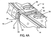
- Figures 3, 4 , 4A and 5 show one preferred structure of a joint as at 16 or 18 in Figure 1 . All are viewed from the outside edge of the snowshoe.
- Figure 3 shows the joint 16 as secured together, revealing the metal traction rail 26 extending from the bottom of the snowshoe body.
- Figure 4 shows the joint 16 opened prior to full assembly, with the fore deck section 12 separated and spaced slightly away from the aft deck section 14. The outside of the snowshoe is visible nearest in Figure 4 .
- the structural rail 26, which is generally a vertically-disposed member, with traction teeth such as shown in Figure 1 includes generally horizontal connecting flanges such as seen at 26b in the drawing. These are also visible in the embodiment in Figure 2 , shown with securement holes 26c.
- connection holes on the rail are not seen in Figure 4 , but mating fastener holes 36 and 38 are seen in the aft deck section 14 and fore deck section 12 in this narrow rim region where the joint 16 occurs.
- the fastener openings 36, 38 are shown with countersink recesses 36a and 38a for the heads of rivets, machine bolts or other fasteners. See also Figures 4A , 5 and 6 .
- Figures 4 , 4A and 5 also show that the narrow connecting portions of the fore deck section 12 and the aft deck section 14 are formed with an overlapping joint for a secure connection.
- the overlapping joint construction includes an inner flange or ridge 40 that extends forward from the aft section, at a laterally inward, receded position as shown.
- This member which is shaped and curved generally in accordance with the outer shape of the narrow region of the two sections 14 and 12, fits into a complementarily shaped socket 42 formed inward of an outer edge flange 43; the socket 42 extends around this region of the fore section 12, as illustrated particularly in Figure 4A , to form a tight joint.
- this joint connection can include a further, inner connector flange 44 on the fore section 12, to further overlap in the joint, just inside the flange 40 of the aft section 14.
- the connected joint 16 is composed of three overlapping layers, a layer or ridge 40 protruding from the aft deck section 14 extending between two layers 43 and 44 in the fore deck section 12. This produces a high integrity joint, but one which can allow some relative twisting motion at the joint.
- Figures 5 and 6 show fastener holes 26c in the metal rail 26, for receiving fasteners through the fastener holes 38 in the fore section 12 ( Figure 5 ) and 36 in the aft deck section 14 ( Figure 6 ). Rivets or machine bolts (not shown) pass through the fastener holes 36, 38 and through the rail holes 26c to secure the two deck sections to the rail 26 at the joint.
- the aft deck section 14 is shown in Figure 6 , along with the metal rail 26, again viewed from the outside edge of the snowshoe.
- the traction edge 26d extends down at the inner side of its narrow rim at the joint, that is, adjacent to the central opening 11 in the snowshoe.
- a fastener extends through the fastener opening 36 and through the fastener hole 26c in the rail, the latter being below the hole 36 bit not seen in Figure 6 .
- Figures 7 and 8 show a side view of a snowshoe 50 having a joint 52 between a fore snowshoe body section 54 and an aft snowshoe body section 56.
- the joint 52 can be made generally as described above, with both fore and aft sections 54 and 56 being bolted or riveted to a metal structural rail 58 that also serves as a traction element, as shown, with teeth 60 extending downward toward terrain.
- Figure 8 bottom plan shows that the metal rail/traction element 58 has several horizontal flanges 58b for fasteners 62 to secure the rail member to the fore and aft molded plastic sections.
- Figures 7 and 8 show a pin connection 64 that connects a footbed/crampon mounting 66 to the metal structural rail 58 to allow pivoting of the footbed/crampon assembly within a central opening of the snowshoe, such as the opening 11 or 32 shown in Figure 1 or 2 .
- Figures 9 and 10 show another form of rail joint wherein the joint is made flexible through an angled connection.
- the two snowshoe sections 70 and 72 joined via obliquely angled horizontal deck joint edges 74 and 76, as shown in both Figures 9 and 10 , and via abutting vertical plates 78 and 80 that are integrally molded with the sections.
- the vertical plates 78, 80 are shown abutted in contact, and they can be secured together by a fastener through those abutted plates (not shown).
- Figure 11 shows a snowshoe of the invention being subjected to torsion by a person applying a twisting moment, such that the forward end or nose 24 is twisted relative to the aft end 28.
- the crampon/binding assembly 82 is seen in this view, pivotally connected to the traction rail at each side.
- a torsional force applied to the snowshoe by uneven terrain and from a user of average weight (150 to 170 pounds) will create an angular deflection of about 15° to 20° or more in the snowshoe, between forward and aft ends. As explained above, this is achieved through the joints that connect fore and aft sections, as well as by the material and thickness of material used.
- the structural traction rails allow this torsional flexibility while acting as load-bearing spars for flexure strength for the length of the snowshoe.
- Figure 12 shows schematically a part of the snowshoe including a portion of the molded deck rim 20, 22 and a structural traction rail 26, secured to the underside of the deck.
- the drawing shows a metal portion 84 of the crampon/binding assembly 82, where this crampon assembly is secured to the rail 26 via the pin connection 64.
- the metal portion 84 extends away from the rail 26, which is inward of the snowshoe (toward the viewer in Figure 12 ), as indicated by the sectioned region 86.
- This drawing indicates one method for rotation-limiting the crampon/binding assembly.
- a tab 88 which is fixed to the rail (which can be an extension of a protruding end 90 of the tab into a hole in the rail), co-acts with the pivoting crampon/binding structure 84 to allow rotation only through an arc as defined by an arcuate cutout area 92 in the metal piece 84.
- the joints 16, 18 provide for the torsional flexibility of the snowshoe in combination with the flexibility of the snowshoe molded deck sections themselves, a function of material and thickness and any reinforcing patterns molded into the deck.
- the two deck sections can be of different materials, not only for torsional flexibility or rigidity but to provide one section with higher strength or toughness requirements than the other. Properties can be tailored; colors can be different.
Landscapes
- Road Paving Structures (AREA)
- Tires In General (AREA)
Description
- This invention concerns snowshoes, particularly snowshoes of molded plastic or composite material, and the invention encompasses a molded snowshoe with improved ability to adapt to uneven terrain.
- Traction and stability on a varied terrain are valuable attributes for a snowshoe. One way to allow enhanced traction and stability is to provide a snowshoe structure which can adapt to various surface contours to effect better contact with the surface, and thus enhanced traction and stability. This invention provides a structure with improved ability to adapt to and make contact with the snow or ice surface on which the snowshoe is used.
- Typical snowshoes provide flotation, traction and stability by the incorporation of flotation means (primarily a deck), traction means (cleats or rails), and a means to attach the user's foot to a relatively rigid structure (a boot binding).
- The traditional frame based snowshoe has a peripheral framed structure that is essentially rigid. This is required to suspend and support the traditional flotation surfaces that consist of flexible members such as rawhide strips, coated fabrics or thin plastic sheets. Traction elements are attached to the underside of this construction for improved traction on ice and snow surfaces. A binding of some type is attached to the structure to receive the user's foot. The traditional framed snowshoe construction thus teaches the need for a rigid frame surrounding the periphery of the snowshoe, and a flexible decking material suspended within the frame. The flexible decking is inherently too flexible to bear the flotation loads of the snowshoe without the support of the peripheral frame.
- It can be advantageous with such a construction to allow the traction elements attached to the snowshoe structure to conform to the contours of the snow and ice surface by providing some level of relative flexibility or suspension from the generally rigid structure of the snowshoe. The flexible decking snowshoe suspends some traction elements on the deck, and suspends the binding (with toe cleat) somewhat, and thus adapts to some extent to the terrain. Other prior approaches using this concept include the use of various suspension systems such as in K2 Snowshoes Patent No.
6,898,874 - More recently, constructions of snowshoes have been developed that consist of flotation surfaces formed of materials such as injection molded plastic, of a thickness and stiffness such as not to require peripheral frames to help resist and support the flotation loads associated with snowshoeing. One such prior art example can be found in the MSR Denali model snowshoe made of a molded one piece surface comprising the flotation surface of the snowshoe. Additional structure is provided in the form of two steel rails running longitudinally along the lower side of the molded decking surface, which also serve as traction elements. This prior art teaches the importance of structural rigidity through the combination of the structure of the longitudinal metal rails, along with structural channels molded into the decking structure of the snowshoe. See, for example, MSR Patents Nos.
5,469,643 5,517,773 5,921,007 - In the described MSR snowshoe, the binding of the snowshoe was attached to the longitudinal traction rails in a pivoting fashion. A certain degree of structural flexibility of the overall structure is obtained by this arrangement. However, the structural rigidity of this construction is also somewhat limiting on the degree to which the structure can conform to the underlying contours. Further, the need to use one material for the entire deck surface for such constructions can be a limitation in the selection of materials to meet the various requirements of the snowshoe structure.
- The above are examples of ways in which the prior art has achieved the required flotation and structure required of a snowshoe combined with contact and traction with the underlying terrain surface.
- The prior art also discloses a compound deck snowshoe, with an additional piece of deck structure or "tail extender" that can be added or taken off the snowshoe body by the user, as a means to alter the degree of flotation of the snowshoe, as in Patents Nos.
5,517,773 6,195,919 6,006,453 6,226,899 6,195,919 - There is a need for a molded or composite snowshoe that has a deck rigidity sufficient for the needed flotation while also affording a torsional (warping) flexibility that allows the traction elements or cleats on the snowshoe bottom to contact uneven terrain.
-
US 4,720,927 describes a snowshoe having a flexible framework demountably engaged in a fabric shell. The individual elements of the framework are rigid but are releasably joined together through rotatable joints so as to provide the flexible framework. The fabric shell forms the deck for the snowshoe and holds the various rigid elements together into the flexible framework. A shoe clamp on the top surface of the fabric deck is mounted to a cleat on the bottom surface of the fabric deck. -
US 5,921,007 describes a snowshoe including at least one tail extender to provide variable flotation characteristics and traction bars to provide improved side slip protection such as when traversing steep terrain. The snowshoe is thereby especially advantageous for use in back country mountaineering. A three (or more) point attachment mechanism is disclosed for coupling the tail extender to the flotation plate of snowshoe so as to reduce stress on the coupling elements and provide a more secure interface. - A molded snowshoe construction in accordance with the invention includes the features of appended independent claim 1. Further embodiments are defined in the dependent claims. The snowshoe further includes a decking surface constructed of a material and of such thickness that support from a peripheral frame is not needed. A typical such snowshoe decking can be formed of molded plastic materials of approximately 3 mm thickness, or molded fiber reinforced composite of somewhat lesser thickness.
- The molded snowshoe of the invention is constructed in a way so as to allow the cleats or traction elements of the snowshoe to contact the underlying terrain surface contours even when the surface is uneven, greatly improving traction. This is achieved by improving the structural flexibility of the snowshoe by forming the deck of the molded snowshoe in two or more separate pieces connected together. These pieces are molded of materials and of a thickness such they are able to bear the flotation loads required by the snowshoe. Structural integrity of the snowshoe is obtained by the use of elongated structural members, such as metal rails on the snowshoe bottom, which extend continuously through a joint between the deck segments, but the design affords torsional flexibility of the snowshoe.
- Preferably the multi-section deck structure is formed with a fore deck section and an aft deck section. The joint preferably is at two locations, both being narrow outer rims at left and right, adjacent to a large central opening in which the snowshoe binding is suspended. The sections are joined in these narrow regions in a way that allows for torsional flexibility of the snowshoe, improving flexibility to accommodate deformation so that the cleats or traction elements at the bottom of the snowshoe can better adapt to uneven terrain, to improve traction. The positioning of the joints is designed to allow conforming deformation in a way that will optimally adapt to terrain.
- According to the invention, two main longitudinal structural elements span the region where the two deck sections meet. These structural elements advantageously comprise metal rails extending through most of the length of the snowshoe and serving also as traction elements on the underside of the snowshoe. Further, the boot binding can be supported by the metal rails, which applies the load from the user directly to these elongated metal structural elements that also preferably serve as traction rails.
- The compound molded deck structure of the invention has the further advantage that the fore deck and aft deck sections can be formed of materials with different properties, such that each section, and portions within each section (via thickness variation), can be tailored to achieve a degree of local flexibility which serves the objective of the overall structure.
- Accordingly, it is among the objects of this invention to achieve in a molded snowshoe a better ability to adapt to uneven terrain and to make good traction with the terrain, while still maintaining the strength, needed flotation and structural integrity of a molded snowshoe. These and other objects, advantages and features of the invention will be apparent from the following description of a preferred embodiment, considered along with the accompanying drawings.
-
-
Figure 1 is a perspective view showing a molded snowshoe body according to the invention, shown without binding. -
Figure 2 is a bottom view of a somewhat modified snowshoe body. -
Figure 3 is a perspective detail view showing one of a plurality of joints in the snowshoe body, between sections. -
Figures 4 and4A are enlarged perspective views again showing a portion of the snowshoe body and a joint between the sections, partially separated in these views. The two views are from different angles. -
Figure 5 is a perspective detail view showing the same region of the snowshoe, revealing a metal with reinforcing rail, and with one of the snowshoe sections removed. -
Figure 6 is another perspective view, showing the same structure from an opposite side. -
Figure 7 is a side elevation view showing another form of joint between snowshoe body sections and rail sections. -
Figure 8 is a bottom view showing the construction ofFigure 7 . -
Figure 9 is a perspective view showing a different embodiment of a joint between snowshoe sections, according to the invention. -
Figure 10 is another view of the joint construction shown inFigure 9 . -
Figure 11 is a perspective view showing a snowshoe of the invention exhibiting torsional flexibility and deflection. -
Figure 12 is a detailed elevation view showing a pivoted connector of a crampon/binding assembly to a traction rail in the snowshoe. -
Figure 1 shows asnowshoe body 10 of the invention, in one preferred form. Thesnowshoe body 10 is molded of plastic material, preferably injection molded of an uncrosslinked polymer such as polypropylene, nylon or urethane. The plastic may be without reinforcing fibers, or it can be reinforced if desired. A compression molded thermoset resin reinforced with fibers such as glass could be used. - In this form of the invention the snowshoe body has a large
central opening 11 for a crampon/boot binding assembly, in this case a boot binding that includes a heel support area (as opposed to snowshoes that allow the boot heel to rest on a rear deck area, such as inFigure 2 ). As seen in the drawing, the snowshoe body has a fore section orfore deck 12 and an aft section oraft deck 14, these being secured together at a joint comprised of left and right junctures orjoints outer rim regions joint connection - As the drawings indicate, the joint formed by the
connections snowshoe nose portion 24 and generally in a region where a snowshoe binding (not shown) will be supported for pitch pivoting movement. -
Figure 1 also shows atraction rail 26 included on each side, preferably extending from the nose back to asnowshoe tail 28. Theserails 26 act as structural members as well, adding flexure strength, and are further discussed below. They can support the binding, such as by supporting a pivot shaft. -
Figure 2 shows adifferent snowshoe body 30, with a smaller central opening 32 for a binding, not shown. In this design the user's boot will rest on the snowshoe deck, in a region generally indicated at 34. This view shows the snowshoe bottom, including the metal traction rails 26 at each side. The rails may be sinuous in shape to accommodate the shape of the snowshoe, or they could be linear, based on snowshoe configuration. The sinuous shape helps in achieving traction. It is important that these metal rails extend through thejoint connections -
Figures 3, 4 ,4A and5 show one preferred structure of a joint as at 16 or 18 inFigure 1 . All are viewed from the outside edge of the snowshoe.Figure 3 shows the joint 16 as secured together, revealing themetal traction rail 26 extending from the bottom of the snowshoe body.Figure 4 shows the joint 16 opened prior to full assembly, with thefore deck section 12 separated and spaced slightly away from theaft deck section 14. The outside of the snowshoe is visible nearest inFigure 4 . As illustrated, thestructural rail 26, which is generally a vertically-disposed member, with traction teeth such as shown inFigure 1 , includes generally horizontal connecting flanges such as seen at 26b in the drawing. These are also visible in the embodiment inFigure 2 , shown withsecurement holes 26c. These connection holes on the rail are not seen inFigure 4 , but mating fastener holes 36 and 38 are seen in theaft deck section 14 andfore deck section 12 in this narrow rim region where the joint 16 occurs. Thefastener openings countersink recesses Figures 4A ,5 and 6 . -
Figures 4 ,4A and5 also show that the narrow connecting portions of thefore deck section 12 and theaft deck section 14 are formed with an overlapping joint for a secure connection. The overlapping joint construction includes an inner flange orridge 40 that extends forward from the aft section, at a laterally inward, receded position as shown. This member, which is shaped and curved generally in accordance with the outer shape of the narrow region of the twosections socket 42 formed inward of anouter edge flange 43; thesocket 42 extends around this region of thefore section 12, as illustrated particularly inFigure 4A , to form a tight joint. As seen inFigure 4A , this joint connection can include a further,inner connector flange 44 on thefore section 12, to further overlap in the joint, just inside theflange 40 of theaft section 14. Thus, the connected joint 16 is composed of three overlapping layers, a layer orridge 40 protruding from theaft deck section 14 extending between twolayers fore deck section 12. This produces a high integrity joint, but one which can allow some relative twisting motion at the joint. -
Figures 5 and 6 show fastener holes 26c in themetal rail 26, for receiving fasteners through the fastener holes 38 in the fore section 12 (Figure 5 ) and 36 in the aft deck section 14 (Figure 6 ). Rivets or machine bolts (not shown) pass through the fastener holes 36, 38 and through the rail holes 26c to secure the two deck sections to therail 26 at the joint. Theaft deck section 14 is shown inFigure 6 , along with themetal rail 26, again viewed from the outside edge of the snowshoe. Thetraction edge 26d extends down at the inner side of its narrow rim at the joint, that is, adjacent to thecentral opening 11 in the snowshoe. Again, a fastener, not shown, extends through thefastener opening 36 and through thefastener hole 26c in the rail, the latter being below thehole 36 bit not seen inFigure 6 . -
Figures 7 and8 show a side view of a snowshoe 50 having a joint 52 between a foresnowshoe body section 54 and an aftsnowshoe body section 56. The joint 52 can be made generally as described above, with both fore andaft sections structural rail 58 that also serves as a traction element, as shown, withteeth 60 extending downward toward terrain.Figure 8 (bottom plan) shows that the metal rail/traction element 58 has severalhorizontal flanges 58b forfasteners 62 to secure the rail member to the fore and aft molded plastic sections.Figures 7 and8 show apin connection 64 that connects a footbed/crampon mounting 66 to the metalstructural rail 58 to allow pivoting of the footbed/crampon assembly within a central opening of the snowshoe, such as theopening 11 or 32 shown inFigure 1 or2 . -
Figures 9 and10 show another form of rail joint wherein the joint is made flexible through an angled connection. In this joint the twosnowshoe sections joint edges Figures 9 and10 , and via abuttingvertical plates Figure 10 thevertical plates -
Figure 11 shows a snowshoe of the invention being subjected to torsion by a person applying a twisting moment, such that the forward end ornose 24 is twisted relative to theaft end 28. The crampon/bindingassembly 82 is seen in this view, pivotally connected to the traction rail at each side. In a preferred embodiment, a torsional force applied to the snowshoe by uneven terrain and from a user of average weight (150 to 170 pounds) will create an angular deflection of about 15° to 20° or more in the snowshoe, between forward and aft ends. As explained above, this is achieved through the joints that connect fore and aft sections, as well as by the material and thickness of material used. The structural traction rails allow this torsional flexibility while acting as load-bearing spars for flexure strength for the length of the snowshoe. -
Figure 12 shows schematically a part of the snowshoe including a portion of the moldeddeck rim structural traction rail 26, secured to the underside of the deck. The drawing shows ametal portion 84 of the crampon/bindingassembly 82, where this crampon assembly is secured to therail 26 via thepin connection 64. Themetal portion 84 extends away from therail 26, which is inward of the snowshoe (toward the viewer inFigure 12 ), as indicated by the sectionedregion 86. This drawing indicates one method for rotation-limiting the crampon/binding assembly. Atab 88, which is fixed to the rail (which can be an extension of aprotruding end 90 of the tab into a hole in the rail), co-acts with the pivoting crampon/bindingstructure 84 to allow rotation only through an arc as defined by anarcuate cutout area 92 in themetal piece 84. - The
joints
Claims (7)
- A molded snowshoe with terrain adaptation,
comprising:a molded snowshoe body (10) in at least two sections (12, 14), the snowshoe body (10) having a large opening (11) in a forward portion (12) of the snowshoe body with a crampon/boot binding assembly for a user's boot supported in the opening,the at least two sections (12, 14) including a forward section (12) extending through a nose region (24) of the snowshoe, and an aft section (14) connected to the forward section (12),the two sections (12, 14) being connected together at left and right narrow rims on either side of the large central opening (11) of the snowshoe body, in a pair of joints (16) that provide for torsional, warping flexibility of the snowshoe body between the forward and aft sections (12, 14); anda left elongated metal traction rail (26) secured to the aft section (14) of the snowshoe body (10) and secured to the forward section (12) of the snowshoe body (10) such that the left metal rail (26) extends across a left one of the pair of joints (16) in the left narrow rim and a right elongated metal traction rail (26) secured to the aft section (14) of the snowshoe body (10) and secured to the forward section (12) of the snowshoe body (10) such that the right metal rail (26) extends across a right one of the pair of joints (16) in the right narrow rim,said elongated traction rails (26) are secured to the bottom of the snowshoe body (10). - The molded snowshoe of claim 1, wherein the crampon/boot binding assembly includes a pivot pin (64) at each side, connecting the crampon/boot binding assembly at each side to the metal traction rail (26) to provide for pitch pivoting of the crampon/boot binding assembly relative to the snowshoe body (10).
- The molded snowshoe of claim 2, further including a rotation limiter (88) at each side of the crampon/boot binding assembly, connected to the pin (64) and positioned to limit rotation of the crampon/boot binding assembly relative to the traction rail (26) and the snowshoe body (10).
- The molded snowshoe of claim 1, wherein the molded snowshoe body sections (12, 14) are secured to horizontal flanges (26b) on the metal traction rails (26), through the length of the metal traction rails (26) including adjacent to the joints (16).
- The molded snowshoe of claim 1, wherein the elongated metal traction rails (26) are sinuous in shape, curving laterally in the length of each rail (26) to enhance forward traction.
- The molded snowshoe of claim 1, wherein the large central opening (11) has a length in the range of about 9" to 16".
- The molded snowshoe of claim 1, including at each joint (16) a socket connection between the narrow rim of the forward section (12) and the narrow rim of the aft section (14), with a curved projecting flange or ridge (26b) of one of the sections extending into a similarly curved socket of the other section.
Applications Claiming Priority (2)
| Application Number | Priority Date | Filing Date | Title |
|---|---|---|---|
| US12/657,610 US8474158B2 (en) | 2010-01-21 | 2010-01-21 | Molded snowshoe with compound deck |
| PCT/US2011/000116 WO2011090797A2 (en) | 2010-01-21 | 2011-01-21 | Molded snowshoe with compound deck |
Publications (3)
| Publication Number | Publication Date |
|---|---|
| EP2672855A2 EP2672855A2 (en) | 2013-12-18 |
| EP2672855A4 EP2672855A4 (en) | 2017-11-22 |
| EP2672855B1 true EP2672855B1 (en) | 2019-05-01 |
Family
ID=44276440
Family Applications (1)
| Application Number | Title | Priority Date | Filing Date |
|---|---|---|---|
| EP11734963.9A Active EP2672855B1 (en) | 2010-01-21 | 2011-01-21 | Molded snowshoe with compound deck |
Country Status (4)
| Country | Link |
|---|---|
| US (1) | US8474158B2 (en) |
| EP (1) | EP2672855B1 (en) |
| CA (1) | CA2786390C (en) |
| WO (1) | WO2011090797A2 (en) |
Families Citing this family (6)
| Publication number | Priority date | Publication date | Assignee | Title |
|---|---|---|---|---|
| US8544193B2 (en) * | 2010-11-12 | 2013-10-01 | K-2 Corporation | Snowshoe with forward frame support |
| US9023455B2 (en) | 2013-01-30 | 2015-05-05 | Ford Global Technologies, Llc | Method of making reinforced composite articles with reduced fiber content in local areas and articles made by the method |
| US8826510B1 (en) * | 2013-02-15 | 2014-09-09 | Ford Global Technologies, Llc | Method of making assemblies including reinforced composite parts with pre-formed rivet receiving buttons and articles made by the method |
| EP2898932A1 (en) * | 2014-01-23 | 2015-07-29 | OBER ALP S.p.A. | Snowshoe with a frame and where the lateral struts are equiped with crampons |
| USD855133S1 (en) * | 2016-12-08 | 2019-07-30 | Jean-Marc Frénée | Snowshoe |
| FR3144525B1 (en) | 2023-01-04 | 2025-10-31 | Martin Plastiques Participations | Two-part snowshoe |
Family Cites Families (18)
| Publication number | Priority date | Publication date | Assignee | Title |
|---|---|---|---|---|
| US4348823A (en) * | 1980-07-24 | 1982-09-14 | Knapp Frank H | Snow life shoes |
| US4720927A (en) | 1986-12-03 | 1988-01-26 | Abegg Sherman T | Demountable snowshoe with flexible frame |
| US5921007A (en) * | 1993-10-22 | 1999-07-13 | Mountain Safety Research, Inc. | Mountaineering snowshoe |
| US5531035A (en) * | 1993-10-22 | 1996-07-02 | Mountain Safety Research | Snowshoe binding assembly |
| US5469643A (en) * | 1993-10-22 | 1995-11-28 | Mountain Safety Research | Snowshoe |
| US5517773A (en) * | 1993-10-22 | 1996-05-21 | Mountain Safety Research | Variable length snowshoe |
| CA2150978A1 (en) * | 1995-06-05 | 1996-12-06 | Maurice Vincent | Snowshoe with adjustable decking tension |
| FR2744642B1 (en) * | 1996-02-09 | 1998-03-20 | Folly S | SNOWSHOE WITH HANGING KNIVES |
| US5718068A (en) * | 1996-10-17 | 1998-02-17 | Sawyer; Ryan | Snowshoe frame with flexible rear section |
| US6006453A (en) * | 1997-01-23 | 1999-12-28 | Tubbs Snowshoe Company Llc | Snowshoe construction |
| FR2760374B1 (en) * | 1997-03-05 | 1999-06-04 | A J R | REMOVABLE SPATULA FOR SNOWSHOES |
| KR200191531Y1 (en) * | 2000-03-22 | 2000-08-16 | 남경호 | Crampons |
| KR200232605Y1 (en) * | 2001-02-21 | 2001-10-06 | 송정식 | Crampons |
| KR100394918B1 (en) * | 2001-07-12 | 2003-08-19 | 남경호 | Crampons |
| US6898874B2 (en) * | 2002-01-04 | 2005-05-31 | K2 Snowshoes, Inc. | Snowshoe with two degrees of rotational freedom |
| DE602006014935D1 (en) * | 2005-02-11 | 2010-07-29 | Tsl Sport Equipment | REPLACEABLE COW AND THANKS FOR SNOW SHOES AND SNOWSHOES WITH SUCH A COW AND THOSE THORN |
| FR2896169B1 (en) * | 2006-01-13 | 2010-10-08 | Tsl Sport Equipment | IMPROVEMENT FOR SNOW RACKET OF A TYPE OF WHICH THE SIEVE INCLUDES A TENDERED CANVAS WITHIN A FRAMEWORK |
| US20090007456A1 (en) * | 2007-07-05 | 2009-01-08 | Louis Garneau | Snowshoe accessory |
-
2010
- 2010-01-21 US US12/657,610 patent/US8474158B2/en active Active
-
2011
- 2011-01-21 WO PCT/US2011/000116 patent/WO2011090797A2/en not_active Ceased
- 2011-01-21 EP EP11734963.9A patent/EP2672855B1/en active Active
- 2011-01-21 CA CA2786390A patent/CA2786390C/en not_active Expired - Fee Related
Non-Patent Citations (1)
| Title |
|---|
| None * |
Also Published As
| Publication number | Publication date |
|---|---|
| WO2011090797A3 (en) | 2013-11-14 |
| US20110173844A1 (en) | 2011-07-21 |
| EP2672855A2 (en) | 2013-12-18 |
| WO2011090797A2 (en) | 2011-07-28 |
| EP2672855A4 (en) | 2017-11-22 |
| US8474158B2 (en) | 2013-07-02 |
| CA2786390A1 (en) | 2011-07-28 |
| CA2786390C (en) | 2016-12-13 |
Similar Documents
| Publication | Publication Date | Title |
|---|---|---|
| CA2786390C (en) | Molded snowshoe with compound deck | |
| US6502850B1 (en) | Core for a gliding board | |
| US8844945B2 (en) | Ice skate runner | |
| US10195514B2 (en) | Hockey skate including a one-piece frame with integral pedestals | |
| US5540002A (en) | Snowshoe having a claw plate on the underside of a snowshoe frame | |
| US6612605B2 (en) | Integrated modular glide board | |
| JPH10179835A (en) | Snowboard | |
| US10974123B2 (en) | Ice skate blade | |
| US20020092207A1 (en) | Sole for boot, in particular a sports boot, a method of manufacturing same, and a boot having such a sole | |
| EP2777418A1 (en) | Hockey skate | |
| US5809668A (en) | Composite snowshoe | |
| JPH04231984A (en) | Ski plate having ribs on the upperface | |
| US20030126764A1 (en) | Snowshoe with two degrees of rotational freedom | |
| CN102131554A (en) | An improved frame structure for skates | |
| US6045143A (en) | Toe plate with dual flanges for in-line skate frame | |
| CN88100614A (en) | Sole of sports shoes | |
| US20040187354A1 (en) | Sports boot for a board for gliding | |
| US20070170697A1 (en) | Device for receiving a foot or a boot on a sports apparatus | |
| JPH1066605A (en) | Structure of a spike shoe sole such as a sucker | |
| US20020089150A1 (en) | Snowboard boot with articulating binding interface | |
| JP2012101071A (en) | Snowshoe with forward frame support | |
| US6089580A (en) | Chassis for in-line roller skates | |
| EP2898933B1 (en) | Snowshoe with a frame and where the lateral struts are equiped with crampons | |
| US20090051142A1 (en) | Gliding board with lateral running edges | |
| US7320475B2 (en) | Device for retaining a foot or a boot on a sports apparatus |
Legal Events
| Date | Code | Title | Description |
|---|---|---|---|
| PUAI | Public reference made under article 153(3) epc to a published international application that has entered the european phase |
Free format text: ORIGINAL CODE: 0009012 |
|
| AK | Designated contracting states |
Kind code of ref document: A2 Designated state(s): AL AT BE BG CH CY CZ DE DK EE ES FI FR GB GR HR HU IE IS IT LI LT LU LV MC MK MT NL NO PL PT RO RS SE SI SK SM TR |
|
| 17P | Request for examination filed |
Effective date: 20140514 |
|
| RBV | Designated contracting states (corrected) |
Designated state(s): AL AT BE BG CH CY CZ DE DK EE ES FI FR GB GR HR HU IE IS IT LI LT LU LV MC MK MT NL NO PL PT RO RS SE SI SK SM TR |
|
| A4 | Supplementary search report drawn up and despatched |
Effective date: 20171024 |
|
| RIC1 | Information provided on ipc code assigned before grant |
Ipc: A43B 5/04 20060101AFI20171018BHEP Ipc: A43C 15/06 20060101ALI20171018BHEP Ipc: A43B 5/18 20060101ALI20171018BHEP Ipc: A63C 13/00 20060101ALI20171018BHEP |
|
| GRAP | Despatch of communication of intention to grant a patent |
Free format text: ORIGINAL CODE: EPIDOSNIGR1 |
|
| STAA | Information on the status of an ep patent application or granted ep patent |
Free format text: STATUS: GRANT OF PATENT IS INTENDED |
|
| INTG | Intention to grant announced |
Effective date: 20181204 |
|
| GRAS | Grant fee paid |
Free format text: ORIGINAL CODE: EPIDOSNIGR3 |
|
| GRAA | (expected) grant |
Free format text: ORIGINAL CODE: 0009210 |
|
| STAA | Information on the status of an ep patent application or granted ep patent |
Free format text: STATUS: THE PATENT HAS BEEN GRANTED |
|
| RAP1 | Party data changed (applicant data changed or rights of an application transferred) |
Owner name: K2 SPORTS, LLC |
|
| AK | Designated contracting states |
Kind code of ref document: B1 Designated state(s): AL AT BE BG CH CY CZ DE DK EE ES FI FR GB GR HR HU IE IS IT LI LT LU LV MC MK MT NL NO PL PT RO RS SE SI SK SM TR |
|
| REG | Reference to a national code |
Ref country code: GB Ref legal event code: FG4D |
|
| REG | Reference to a national code |
Ref country code: CH Ref legal event code: EP Ref country code: AT Ref legal event code: REF Ref document number: 1125738 Country of ref document: AT Kind code of ref document: T Effective date: 20190515 |
|
| REG | Reference to a national code |
Ref country code: DE Ref legal event code: R096 Ref document number: 602011058505 Country of ref document: DE |
|
| REG | Reference to a national code |
Ref country code: IE Ref legal event code: FG4D |
|
| REG | Reference to a national code |
Ref country code: NL Ref legal event code: MP Effective date: 20190501 |
|
| REG | Reference to a national code |
Ref country code: LT Ref legal event code: MG4D |
|
| PG25 | Lapsed in a contracting state [announced via postgrant information from national office to epo] |
Ref country code: FI Free format text: LAPSE BECAUSE OF FAILURE TO SUBMIT A TRANSLATION OF THE DESCRIPTION OR TO PAY THE FEE WITHIN THE PRESCRIBED TIME-LIMIT Effective date: 20190501 Ref country code: LT Free format text: LAPSE BECAUSE OF FAILURE TO SUBMIT A TRANSLATION OF THE DESCRIPTION OR TO PAY THE FEE WITHIN THE PRESCRIBED TIME-LIMIT Effective date: 20190501 Ref country code: NL Free format text: LAPSE BECAUSE OF FAILURE TO SUBMIT A TRANSLATION OF THE DESCRIPTION OR TO PAY THE FEE WITHIN THE PRESCRIBED TIME-LIMIT Effective date: 20190501 Ref country code: AL Free format text: LAPSE BECAUSE OF FAILURE TO SUBMIT A TRANSLATION OF THE DESCRIPTION OR TO PAY THE FEE WITHIN THE PRESCRIBED TIME-LIMIT Effective date: 20190501 Ref country code: ES Free format text: LAPSE BECAUSE OF FAILURE TO SUBMIT A TRANSLATION OF THE DESCRIPTION OR TO PAY THE FEE WITHIN THE PRESCRIBED TIME-LIMIT Effective date: 20190501 Ref country code: SE Free format text: LAPSE BECAUSE OF FAILURE TO SUBMIT A TRANSLATION OF THE DESCRIPTION OR TO PAY THE FEE WITHIN THE PRESCRIBED TIME-LIMIT Effective date: 20190501 Ref country code: HR Free format text: LAPSE BECAUSE OF FAILURE TO SUBMIT A TRANSLATION OF THE DESCRIPTION OR TO PAY THE FEE WITHIN THE PRESCRIBED TIME-LIMIT Effective date: 20190501 Ref country code: PT Free format text: LAPSE BECAUSE OF FAILURE TO SUBMIT A TRANSLATION OF THE DESCRIPTION OR TO PAY THE FEE WITHIN THE PRESCRIBED TIME-LIMIT Effective date: 20190901 Ref country code: NO Free format text: LAPSE BECAUSE OF FAILURE TO SUBMIT A TRANSLATION OF THE DESCRIPTION OR TO PAY THE FEE WITHIN THE PRESCRIBED TIME-LIMIT Effective date: 20190801 |
|
| PG25 | Lapsed in a contracting state [announced via postgrant information from national office to epo] |
Ref country code: GR Free format text: LAPSE BECAUSE OF FAILURE TO SUBMIT A TRANSLATION OF THE DESCRIPTION OR TO PAY THE FEE WITHIN THE PRESCRIBED TIME-LIMIT Effective date: 20190802 Ref country code: LV Free format text: LAPSE BECAUSE OF FAILURE TO SUBMIT A TRANSLATION OF THE DESCRIPTION OR TO PAY THE FEE WITHIN THE PRESCRIBED TIME-LIMIT Effective date: 20190501 Ref country code: RS Free format text: LAPSE BECAUSE OF FAILURE TO SUBMIT A TRANSLATION OF THE DESCRIPTION OR TO PAY THE FEE WITHIN THE PRESCRIBED TIME-LIMIT Effective date: 20190501 Ref country code: BG Free format text: LAPSE BECAUSE OF FAILURE TO SUBMIT A TRANSLATION OF THE DESCRIPTION OR TO PAY THE FEE WITHIN THE PRESCRIBED TIME-LIMIT Effective date: 20190801 |
|
| REG | Reference to a national code |
Ref country code: AT Ref legal event code: MK05 Ref document number: 1125738 Country of ref document: AT Kind code of ref document: T Effective date: 20190501 |
|
| PG25 | Lapsed in a contracting state [announced via postgrant information from national office to epo] |
Ref country code: IS Free format text: LAPSE BECAUSE OF FAILURE TO SUBMIT A TRANSLATION OF THE DESCRIPTION OR TO PAY THE FEE WITHIN THE PRESCRIBED TIME-LIMIT Effective date: 20190901 |
|
| PG25 | Lapsed in a contracting state [announced via postgrant information from national office to epo] |
Ref country code: SK Free format text: LAPSE BECAUSE OF FAILURE TO SUBMIT A TRANSLATION OF THE DESCRIPTION OR TO PAY THE FEE WITHIN THE PRESCRIBED TIME-LIMIT Effective date: 20190501 Ref country code: EE Free format text: LAPSE BECAUSE OF FAILURE TO SUBMIT A TRANSLATION OF THE DESCRIPTION OR TO PAY THE FEE WITHIN THE PRESCRIBED TIME-LIMIT Effective date: 20190501 Ref country code: CZ Free format text: LAPSE BECAUSE OF FAILURE TO SUBMIT A TRANSLATION OF THE DESCRIPTION OR TO PAY THE FEE WITHIN THE PRESCRIBED TIME-LIMIT Effective date: 20190501 Ref country code: RO Free format text: LAPSE BECAUSE OF FAILURE TO SUBMIT A TRANSLATION OF THE DESCRIPTION OR TO PAY THE FEE WITHIN THE PRESCRIBED TIME-LIMIT Effective date: 20190501 Ref country code: AT Free format text: LAPSE BECAUSE OF FAILURE TO SUBMIT A TRANSLATION OF THE DESCRIPTION OR TO PAY THE FEE WITHIN THE PRESCRIBED TIME-LIMIT Effective date: 20190501 Ref country code: DK Free format text: LAPSE BECAUSE OF FAILURE TO SUBMIT A TRANSLATION OF THE DESCRIPTION OR TO PAY THE FEE WITHIN THE PRESCRIBED TIME-LIMIT Effective date: 20190501 |
|
| REG | Reference to a national code |
Ref country code: DE Ref legal event code: R097 Ref document number: 602011058505 Country of ref document: DE |
|
| PG25 | Lapsed in a contracting state [announced via postgrant information from national office to epo] |
Ref country code: SM Free format text: LAPSE BECAUSE OF FAILURE TO SUBMIT A TRANSLATION OF THE DESCRIPTION OR TO PAY THE FEE WITHIN THE PRESCRIBED TIME-LIMIT Effective date: 20190501 Ref country code: IT Free format text: LAPSE BECAUSE OF FAILURE TO SUBMIT A TRANSLATION OF THE DESCRIPTION OR TO PAY THE FEE WITHIN THE PRESCRIBED TIME-LIMIT Effective date: 20190501 |
|
| PLBE | No opposition filed within time limit |
Free format text: ORIGINAL CODE: 0009261 |
|
| STAA | Information on the status of an ep patent application or granted ep patent |
Free format text: STATUS: NO OPPOSITION FILED WITHIN TIME LIMIT |
|
| PG25 | Lapsed in a contracting state [announced via postgrant information from national office to epo] |
Ref country code: TR Free format text: LAPSE BECAUSE OF FAILURE TO SUBMIT A TRANSLATION OF THE DESCRIPTION OR TO PAY THE FEE WITHIN THE PRESCRIBED TIME-LIMIT Effective date: 20190501 |
|
| 26N | No opposition filed |
Effective date: 20200204 |
|
| PG25 | Lapsed in a contracting state [announced via postgrant information from national office to epo] |
Ref country code: PL Free format text: LAPSE BECAUSE OF FAILURE TO SUBMIT A TRANSLATION OF THE DESCRIPTION OR TO PAY THE FEE WITHIN THE PRESCRIBED TIME-LIMIT Effective date: 20190501 |
|
| PG25 | Lapsed in a contracting state [announced via postgrant information from national office to epo] |
Ref country code: SI Free format text: LAPSE BECAUSE OF FAILURE TO SUBMIT A TRANSLATION OF THE DESCRIPTION OR TO PAY THE FEE WITHIN THE PRESCRIBED TIME-LIMIT Effective date: 20190501 |
|
| PG25 | Lapsed in a contracting state [announced via postgrant information from national office to epo] |
Ref country code: MC Free format text: LAPSE BECAUSE OF FAILURE TO SUBMIT A TRANSLATION OF THE DESCRIPTION OR TO PAY THE FEE WITHIN THE PRESCRIBED TIME-LIMIT Effective date: 20190501 |
|
| REG | Reference to a national code |
Ref country code: CH Ref legal event code: PL |
|
| GBPC | Gb: european patent ceased through non-payment of renewal fee |
Effective date: 20200121 |
|
| REG | Reference to a national code |
Ref country code: BE Ref legal event code: MM Effective date: 20200131 |
|
| PG25 | Lapsed in a contracting state [announced via postgrant information from national office to epo] |
Ref country code: LU Free format text: LAPSE BECAUSE OF NON-PAYMENT OF DUE FEES Effective date: 20200121 Ref country code: GB Free format text: LAPSE BECAUSE OF NON-PAYMENT OF DUE FEES Effective date: 20200121 |
|
| PG25 | Lapsed in a contracting state [announced via postgrant information from national office to epo] |
Ref country code: BE Free format text: LAPSE BECAUSE OF NON-PAYMENT OF DUE FEES Effective date: 20200131 Ref country code: LI Free format text: LAPSE BECAUSE OF NON-PAYMENT OF DUE FEES Effective date: 20200131 Ref country code: CH Free format text: LAPSE BECAUSE OF NON-PAYMENT OF DUE FEES Effective date: 20200131 |
|
| PG25 | Lapsed in a contracting state [announced via postgrant information from national office to epo] |
Ref country code: IE Free format text: LAPSE BECAUSE OF NON-PAYMENT OF DUE FEES Effective date: 20200121 |
|
| PGFP | Annual fee paid to national office [announced via postgrant information from national office to epo] |
Ref country code: DE Payment date: 20210127 Year of fee payment: 11 |
|
| PG25 | Lapsed in a contracting state [announced via postgrant information from national office to epo] |
Ref country code: MT Free format text: LAPSE BECAUSE OF FAILURE TO SUBMIT A TRANSLATION OF THE DESCRIPTION OR TO PAY THE FEE WITHIN THE PRESCRIBED TIME-LIMIT Effective date: 20190501 Ref country code: CY Free format text: LAPSE BECAUSE OF FAILURE TO SUBMIT A TRANSLATION OF THE DESCRIPTION OR TO PAY THE FEE WITHIN THE PRESCRIBED TIME-LIMIT Effective date: 20190501 |
|
| PG25 | Lapsed in a contracting state [announced via postgrant information from national office to epo] |
Ref country code: MK Free format text: LAPSE BECAUSE OF FAILURE TO SUBMIT A TRANSLATION OF THE DESCRIPTION OR TO PAY THE FEE WITHIN THE PRESCRIBED TIME-LIMIT Effective date: 20190501 |
|
| REG | Reference to a national code |
Ref country code: DE Ref legal event code: R119 Ref document number: 602011058505 Country of ref document: DE |
|
| PG25 | Lapsed in a contracting state [announced via postgrant information from national office to epo] |
Ref country code: DE Free format text: LAPSE BECAUSE OF NON-PAYMENT OF DUE FEES Effective date: 20220802 |
|
| PGFP | Annual fee paid to national office [announced via postgrant information from national office to epo] |
Ref country code: FR Payment date: 20230125 Year of fee payment: 13 |
|
| PG25 | Lapsed in a contracting state [announced via postgrant information from national office to epo] |
Ref country code: FR Free format text: LAPSE BECAUSE OF NON-PAYMENT OF DUE FEES Effective date: 20240131 |
|
| PG25 | Lapsed in a contracting state [announced via postgrant information from national office to epo] |
Ref country code: FR Free format text: LAPSE BECAUSE OF NON-PAYMENT OF DUE FEES Effective date: 20240131 |