EP2672543A1 - Rechargeable battery pack - Google Patents
Rechargeable battery pack Download PDFInfo
- Publication number
- EP2672543A1 EP2672543A1 EP13163987.4A EP13163987A EP2672543A1 EP 2672543 A1 EP2672543 A1 EP 2672543A1 EP 13163987 A EP13163987 A EP 13163987A EP 2672543 A1 EP2672543 A1 EP 2672543A1
- Authority
- EP
- European Patent Office
- Prior art keywords
- rechargeable battery
- pcm
- insulating member
- battery according
- buffer
- Prior art date
- Legal status (The legal status is an assumption and is not a legal conclusion. Google has not performed a legal analysis and makes no representation as to the accuracy of the status listed.)
- Granted
Links
Images







Classifications
-
- H—ELECTRICITY
- H01—ELECTRIC ELEMENTS
- H01M—PROCESSES OR MEANS, e.g. BATTERIES, FOR THE DIRECT CONVERSION OF CHEMICAL ENERGY INTO ELECTRICAL ENERGY
- H01M10/00—Secondary cells; Manufacture thereof
- H01M10/04—Construction or manufacture in general
- H01M10/0431—Cells with wound or folded electrodes
-
- H—ELECTRICITY
- H01—ELECTRIC ELEMENTS
- H01M—PROCESSES OR MEANS, e.g. BATTERIES, FOR THE DIRECT CONVERSION OF CHEMICAL ENERGY INTO ELECTRICAL ENERGY
- H01M50/00—Constructional details or processes of manufacture of the non-active parts of electrochemical cells other than fuel cells, e.g. hybrid cells
- H01M50/50—Current conducting connections for cells or batteries
- H01M50/572—Means for preventing undesired use or discharge
-
- H—ELECTRICITY
- H01—ELECTRIC ELEMENTS
- H01M—PROCESSES OR MEANS, e.g. BATTERIES, FOR THE DIRECT CONVERSION OF CHEMICAL ENERGY INTO ELECTRICAL ENERGY
- H01M10/00—Secondary cells; Manufacture thereof
- H01M10/42—Methods or arrangements for servicing or maintenance of secondary cells or secondary half-cells
- H01M10/425—Structural combination with electronic components, e.g. electronic circuits integrated to the outside of the casing
-
- H—ELECTRICITY
- H01—ELECTRIC ELEMENTS
- H01M—PROCESSES OR MEANS, e.g. BATTERIES, FOR THE DIRECT CONVERSION OF CHEMICAL ENERGY INTO ELECTRICAL ENERGY
- H01M50/00—Constructional details or processes of manufacture of the non-active parts of electrochemical cells other than fuel cells, e.g. hybrid cells
- H01M50/10—Primary casings; Jackets or wrappings
- H01M50/116—Primary casings; Jackets or wrappings characterised by the material
- H01M50/121—Organic material
-
- H—ELECTRICITY
- H01—ELECTRIC ELEMENTS
- H01M—PROCESSES OR MEANS, e.g. BATTERIES, FOR THE DIRECT CONVERSION OF CHEMICAL ENERGY INTO ELECTRICAL ENERGY
- H01M50/00—Constructional details or processes of manufacture of the non-active parts of electrochemical cells other than fuel cells, e.g. hybrid cells
- H01M50/10—Primary casings; Jackets or wrappings
- H01M50/172—Arrangements of electric connectors penetrating the casing
- H01M50/174—Arrangements of electric connectors penetrating the casing adapted for the shape of the cells
- H01M50/178—Arrangements of electric connectors penetrating the casing adapted for the shape of the cells for pouch or flexible bag cells
-
- H—ELECTRICITY
- H01—ELECTRIC ELEMENTS
- H01M—PROCESSES OR MEANS, e.g. BATTERIES, FOR THE DIRECT CONVERSION OF CHEMICAL ENERGY INTO ELECTRICAL ENERGY
- H01M50/00—Constructional details or processes of manufacture of the non-active parts of electrochemical cells other than fuel cells, e.g. hybrid cells
- H01M50/50—Current conducting connections for cells or batteries
- H01M50/528—Fixed electrical connections, i.e. not intended for disconnection
-
- H—ELECTRICITY
- H01—ELECTRIC ELEMENTS
- H01M—PROCESSES OR MEANS, e.g. BATTERIES, FOR THE DIRECT CONVERSION OF CHEMICAL ENERGY INTO ELECTRICAL ENERGY
- H01M50/00—Constructional details or processes of manufacture of the non-active parts of electrochemical cells other than fuel cells, e.g. hybrid cells
- H01M50/50—Current conducting connections for cells or batteries
- H01M50/543—Terminals
- H01M50/547—Terminals characterised by the disposition of the terminals on the cells
- H01M50/55—Terminals characterised by the disposition of the terminals on the cells on the same side of the cell
-
- H—ELECTRICITY
- H01—ELECTRIC ELEMENTS
- H01M—PROCESSES OR MEANS, e.g. BATTERIES, FOR THE DIRECT CONVERSION OF CHEMICAL ENERGY INTO ELECTRICAL ENERGY
- H01M50/00—Constructional details or processes of manufacture of the non-active parts of electrochemical cells other than fuel cells, e.g. hybrid cells
- H01M50/50—Current conducting connections for cells or batteries
- H01M50/543—Terminals
- H01M50/552—Terminals characterised by their shape
- H01M50/553—Terminals adapted for prismatic, pouch or rectangular cells
- H01M50/557—Plate-shaped terminals
-
- H—ELECTRICITY
- H01—ELECTRIC ELEMENTS
- H01M—PROCESSES OR MEANS, e.g. BATTERIES, FOR THE DIRECT CONVERSION OF CHEMICAL ENERGY INTO ELECTRICAL ENERGY
- H01M50/00—Constructional details or processes of manufacture of the non-active parts of electrochemical cells other than fuel cells, e.g. hybrid cells
- H01M50/50—Current conducting connections for cells or batteries
- H01M50/572—Means for preventing undesired use or discharge
- H01M50/574—Devices or arrangements for the interruption of current
-
- H—ELECTRICITY
- H01—ELECTRIC ELEMENTS
- H01M—PROCESSES OR MEANS, e.g. BATTERIES, FOR THE DIRECT CONVERSION OF CHEMICAL ENERGY INTO ELECTRICAL ENERGY
- H01M50/00—Constructional details or processes of manufacture of the non-active parts of electrochemical cells other than fuel cells, e.g. hybrid cells
- H01M50/50—Current conducting connections for cells or batteries
- H01M50/572—Means for preventing undesired use or discharge
- H01M50/584—Means for preventing undesired use or discharge for preventing incorrect connections inside or outside the batteries
- H01M50/588—Means for preventing undesired use or discharge for preventing incorrect connections inside or outside the batteries outside the batteries, e.g. incorrect connections of terminals or busbars
-
- H—ELECTRICITY
- H01—ELECTRIC ELEMENTS
- H01M—PROCESSES OR MEANS, e.g. BATTERIES, FOR THE DIRECT CONVERSION OF CHEMICAL ENERGY INTO ELECTRICAL ENERGY
- H01M50/00—Constructional details or processes of manufacture of the non-active parts of electrochemical cells other than fuel cells, e.g. hybrid cells
- H01M50/50—Current conducting connections for cells or batteries
- H01M50/572—Means for preventing undesired use or discharge
- H01M50/584—Means for preventing undesired use or discharge for preventing incorrect connections inside or outside the batteries
- H01M50/59—Means for preventing undesired use or discharge for preventing incorrect connections inside or outside the batteries characterised by the protection means
- H01M50/593—Spacers; Insulating plates
-
- H—ELECTRICITY
- H01—ELECTRIC ELEMENTS
- H01M—PROCESSES OR MEANS, e.g. BATTERIES, FOR THE DIRECT CONVERSION OF CHEMICAL ENERGY INTO ELECTRICAL ENERGY
- H01M2200/00—Safety devices for primary or secondary batteries
-
- H—ELECTRICITY
- H01—ELECTRIC ELEMENTS
- H01M—PROCESSES OR MEANS, e.g. BATTERIES, FOR THE DIRECT CONVERSION OF CHEMICAL ENERGY INTO ELECTRICAL ENERGY
- H01M50/00—Constructional details or processes of manufacture of the non-active parts of electrochemical cells other than fuel cells, e.g. hybrid cells
- H01M50/10—Primary casings; Jackets or wrappings
- H01M50/116—Primary casings; Jackets or wrappings characterised by the material
- H01M50/117—Inorganic material
- H01M50/119—Metals
-
- H—ELECTRICITY
- H01—ELECTRIC ELEMENTS
- H01M—PROCESSES OR MEANS, e.g. BATTERIES, FOR THE DIRECT CONVERSION OF CHEMICAL ENERGY INTO ELECTRICAL ENERGY
- H01M50/00—Constructional details or processes of manufacture of the non-active parts of electrochemical cells other than fuel cells, e.g. hybrid cells
- H01M50/10—Primary casings; Jackets or wrappings
- H01M50/116—Primary casings; Jackets or wrappings characterised by the material
- H01M50/124—Primary casings; Jackets or wrappings characterised by the material having a layered structure
- H01M50/126—Primary casings; Jackets or wrappings characterised by the material having a layered structure comprising three or more layers
- H01M50/129—Primary casings; Jackets or wrappings characterised by the material having a layered structure comprising three or more layers with two or more layers of only organic material
-
- Y—GENERAL TAGGING OF NEW TECHNOLOGICAL DEVELOPMENTS; GENERAL TAGGING OF CROSS-SECTIONAL TECHNOLOGIES SPANNING OVER SEVERAL SECTIONS OF THE IPC; TECHNICAL SUBJECTS COVERED BY FORMER USPC CROSS-REFERENCE ART COLLECTIONS [XRACs] AND DIGESTS
- Y02—TECHNOLOGIES OR APPLICATIONS FOR MITIGATION OR ADAPTATION AGAINST CLIMATE CHANGE
- Y02E—REDUCTION OF GREENHOUSE GAS [GHG] EMISSIONS, RELATED TO ENERGY GENERATION, TRANSMISSION OR DISTRIBUTION
- Y02E60/00—Enabling technologies; Technologies with a potential or indirect contribution to GHG emissions mitigation
- Y02E60/10—Energy storage using batteries
-
- Y—GENERAL TAGGING OF NEW TECHNOLOGICAL DEVELOPMENTS; GENERAL TAGGING OF CROSS-SECTIONAL TECHNOLOGIES SPANNING OVER SEVERAL SECTIONS OF THE IPC; TECHNICAL SUBJECTS COVERED BY FORMER USPC CROSS-REFERENCE ART COLLECTIONS [XRACs] AND DIGESTS
- Y02—TECHNOLOGIES OR APPLICATIONS FOR MITIGATION OR ADAPTATION AGAINST CLIMATE CHANGE
- Y02P—CLIMATE CHANGE MITIGATION TECHNOLOGIES IN THE PRODUCTION OR PROCESSING OF GOODS
- Y02P70/00—Climate change mitigation technologies in the production process for final industrial or consumer products
- Y02P70/50—Manufacturing or production processes characterised by the final manufactured product
Definitions
- a force of restitution by elasticity of the insulating member 30 may be reduced or eliminated, so a phenomenon that the insulating member 30 is separated to come off from the right-angle corner set by the first surface portion 125 and the second portion 126 can be reduced.
- attachment performance of the PCM attached to the insulating member 30 can be enhanced.
Landscapes
- Chemical & Material Sciences (AREA)
- Chemical Kinetics & Catalysis (AREA)
- Electrochemistry (AREA)
- General Chemical & Material Sciences (AREA)
- Engineering & Computer Science (AREA)
- Manufacturing & Machinery (AREA)
- Microelectronics & Electronic Packaging (AREA)
- Inorganic Chemistry (AREA)
- Battery Mounting, Suspending (AREA)
- Connection Of Batteries Or Terminals (AREA)
Abstract
Description
- The present disclosure relates to a rechargeable battery comprising a protection circuit module attached to a bare cell.
- Unlike a primary battery which is not rechargeable, a rechargeable battery can be recharged and discharged. A small-capacity rechargeable battery is used for small portable electronic devices such as mobile phones, notebook computers, camcorders, and the like, while a large-capacity rechargeable battery is used as a motor-driving power source for an electric bike, an electric vehicle, a fork lift, or the like.
- A rechargeable battery pack includes a bare cell and a protection circuit module (PCM) protecting the bare cell. The PCM includes a circuit board forming a protection circuit for protecting the bare cell against an overcharge, an overdischarge, an overcurrent, and a short, and protection elements mounted on the circuit board.
- A pouch type bare cell is configured as a tablet type bare cell, and the bare cell includes a end portion formed at one side of a heat fusion portion of a pouch and the PCM is attached to the end portion by using a double-sided tape. One side of the bare cell and the end portion are formed to be substantially perpendicular to each other, so the double-sided tape is bent at a right angle so as to be attached thereto.
- Thus, a process of attaching the PCM is difficult. Also, due to force of restitution of the double-sided tape at the bent portion, the double-sided tape may be separated from the end portion or come off to cause a defective attachment of the PCM and defective pack dimensions.
- The above information disclosed in this Background section is only for enhancement of understanding of the background of the described technology and therefore it may contain information that does not form the prior art that is already known in this country to a person of ordinary skill in the art.
- The described technology has been made in an effort to provide a rechargeable battery pack having advantages of enhancing workability of attaching a bare cell and a protection circuit module (PCM) and enhancing attachment performance and accuracy of pack dimensions.
- The present invention provides a rechargeable battery according to claim 1. The present invention also provides a method of assembling a rechargeable battery according to claim 16.
- Since the insulating member is bent on the hinge portion and attached to the end portion, when a PCM is attached to the insulating member, the insulating member can be prevented from coming off.
- Preferred features of the invention are defined in claims 2 to 15.
- Thus, workability of attaching the PCM to the bare cell can be enhanced, and performance of attaching the PCM by the insulating member and accuracy of pack dimensions can be enhanced.
-
-
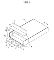
FIG. 1 is a partial exploded perspective view of a rechargeable battery pack according to a first embodiment of the present invention. -
FIG. 2 is a perspective view showing an assembled rechargeable battery pack according to the first embodiment of the present invention. -
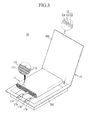
FIG. 3 is an exploded perspective view of a bare cell of the rechargeable battery pack ofFIG. 1 . -
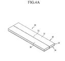
FIG. 4(a) is an unfolded perspective view of a insulating member,FIG 4(b) is an exploded perspective view of the insulating member, andFIG. 4(c) is a perspective view showing a bent state of the insulating member. -
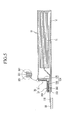
FIG. 5 is a cross-sectional view taken along line V-V of the assembled rechargeable battery pack illustrated inFIG. 1 . -
FIG. 6 is a cross-sectional view taken along line VI-VI inFIG. 2 . -
FIG. 7 is a cross-sectional view taken along line VII-VII inFIG. 2 . -
FIG. 8 is a partial sectional view of a rechargeable battery pack according to a second embodiment of the present invention. -
FIG. 9 is a partial sectional view of a rechargeable battery pack according to a third embodiment of the present invention. -
FIG. 10(a) is an exploded perspective view of the insulating member, andFIG. 10(b) is a perspective view showing a bent state of the insulating member according to a third embodiment of the present invention. - The present invention will be described more fully hereinafter with reference to the accompanying drawings, in which embodiments of the invention are shown. As those skilled in the art would realize, the described embodiments may be modified in various different ways, all without departing from the scope of the present invention. The drawings and description are to be regarded as illustrative in nature and not restrictive. Like reference numerals designate like elements throughout the specification.
-
FIG. 1 is a partial exploded perspective view of a rechargeable battery pack according to a first embodiment of the present invention, andFIG. 2 is a perspective view showing an assembled rechargeable battery pack according to the first embodiment of the present invention. - With reference to
FIGS. 1 and2 , a rechargeable battery pack according to an embodiment of the present invention includes abare cell 10, a protection circuit module (PCM) 20 electrically connected to thebare cell 10, and ainsulating member 30 attaching the PCM to thebare cell 10. -
FIG. 3 is an exploded perspective view of a bare cell accommodated in the rechargeable battery pack ofFIG. 1 . With reference toFIG. 3 , thebare cell 10 includes anelectrode assembly 11 performs charging and discharging, and apouch 12 accommodating theelectrode assembly 11 therein. - The
electrode assembly 11 has a jelly roll shape by disposing a first electrode ('positive electrode' for the sake of convenience) 111 and a second electrode ('negative electrode' for the sake of convenience) with aseparator 113 interposed therebetween and winding them. Theseparator 113 is formed as a polymer film allowing lithium ions to pass therethrough. - The
pouch 12 has a multi-sheet structure covering the exterior of theelectrode assembly 11. For example, thepouch 12 includes apolymer sheet 121 forming an inner surface of thepouch 12 and performing insulation and heat fusion, a PET (polyethyleneterephthalate) sheet, a nylon sheet, or a PET-nylon composite sheet 122 (hereinafter, 'nylon sheet' will be described as an example for the sake of convenience) forming an outer surface to protect the pouch, and ametal sheet 123 providing mechanical strength. Themetal sheet 123 is interposed between thepolymer sheet 121 and thenylon sheet 122 and may be formed as, for example, an aluminum sheet. - Also, the
pouch 12 includes a firstexterior member 201 accommodating theelectrode assembly 11 and a secondexterior member 202 covering theelectrode assembly 11 and heat-fused to the firstexterior member 201 at an outer side of theelectrode assembly 11. The first and secondexterior members polymer sheet 121, thenylon sheet 122, and themetal sheet 123 having the same structure. - The first
exterior member 201 is formed to have a recess structure to accommodate theelectrode assembly 11, and the secondexterior member 202 is formed to be flat to cover theelectrode assembly 11 accommodated in the firstexterior member 201. - Also, the
electrode assembly 11 is formed as a flat plate type electrode assembly, and accordingly, thepouch 12 is formed as a rectangular flat type pouch. Thebare cell 10 is formed by surrounding theelectrode assembly 11 with thepouch 12, thebare cell 10 is formed as a rectangular flat type bare cell overall. - The
electrode assembly 11 further includes a positiveelectrode lead tab 114 connected to an uncoated portion of thepositive electrode 111 and anegative lead tab 115 connected to an uncoated portion of thenegative electrode 112. The positiveelectrode lead tab 114 and the negativeelectrode lead tab 115 are connected to the same lateral surface of theelectrode assembly 11 and led out of the same lateral surface of thepouch 12. - With reference back to
FIGS. 1 and2 , thepositive lead tab 114 and the negativeelectrode lead tab 115 are disposed in a penetrative manner between the first and secondexterior members end portion 124 formed at one side of thepouch 12. - Here, the positive
electrode lead tab 114 and the negativeelectrode lead tab 115 are electrically connected to thepouch 12 by insulatingmembers 18 and 19, respectively. - The
end portion 124 is formed by heat-fusing an end portion of the firstexterior member 201 bent along theelectrode assembly 11 to a planar end portion of the secondexterior member 202 facing the end portion of the firstexterior member 201, at the side from which thepositive lead tab 114 and thenegative lead tab 115 are led out. - Thus, the
end portion 124 includes afirst surface portion 125 formed on a lateral surface of thepouch 12 corresponding to one section of theelectrode assembly 11 and asecond surface portion 126 projecting at a right angle from thefirst surface portion 125 and formed as a heat-fused plane of thepouch 12. Theend portion 124 is therefore formed as an inward facing corner. - In the state of
FIG. 3 , when the first and secondexterior members bare cell 10 in the state ofFIGS. 1 and2 is formed. The protection circuit module (PCM) 20 is attached to thebare cell 10 in the state ofFIGS. 1 and2 . - In order to protect the
bare cell 10 against an overcharge, an overdischarge, an overcurrent, and an external short, thePCM 20 is formed by forming a protection circuit on a substrate andmounting protection elements 21 on the protection circuit. -
FIG. 4(a) is an unfolded perspective view of a insulating member,FIG 4(b) is an exploded perspective view of the insulating member, andFIG. 4(c) is a perspective view showing a bent state of the insulating member. With reference toFIGS. 1 ,2 , and4 , theinsulating member 30 may be bent at a right angle, and formed to firmly maintain the bent state. - Namely, the
insulating member 30 has an area corresponding to theend portion 124, and includes afirst portion 31 corresponding to thefirst surface portion 125 and asecond portion 32 corresponding to thesecond surface portion 126. In the insulatingmember 30, the first andsecond portions - The insulating
member 30 includes a buffer portion 33 stacked in a depth direction of the insulatingmember 30, adhesive layer 34 and insulatinglayer 35 provided on both surfaces of the buffer portion 33. - The insulating
layer 35 may be formed of PET(polyethyleneterephthalate). The insulatinglayer 35 and the buffer portion 33 may be coupled. - For example, the perforated line CL may be formed only on the insulating layer. Alternatively, the perforated line CL may be formed on both the insulating
layer 35 and at least part of the buffer portion. - The buffer portion 33 and the adhesive layer 34 may be completely cut through in a depth direction of the insulating
member 30. (Refer to theFIG. 4(b) ). Accordingly, the buffer portion may be separated with afirst buffer portion 331 positioned on thefist portion 31 and asecond buffer portion 332 positioned on thesecond portion 32. - Accordingly, the adhesive layer 34 may include a first
adhesive layer 341 positioned on thefirst buffer portion 331 and a secondadhesive layer 342 on thesecond buffer portion 332. - The perforated line CL is formed of a plurality of holes which are formed on the insulating layer which includes a first insulating
layer 351 positioned on thefirst buffer portion 331 and a second insulatinglayer 352 positioned on thesecond buffer portion 332. - Accordingly, the perforated line CL allows the first and
second portions member 30 is attached to theend portion 124. Thefirst buffer portion 331 and thesecond buffer portion 332 are in a separated state, and then the firstadhesive layer 341 and the second adhesive layer are in a separated state. - Thus, the first and
second portions first surface portion 125 and thesecond portion surface 126, respectively, and the attached state thereof can be firmly maintained. - Namely, a force of restitution by elasticity of the insulating
member 30 may be reduced or eliminated, so a phenomenon that the insulatingmember 30 is separated to come off from the right-angle corner set by thefirst surface portion 125 and thesecond portion 126 can be reduced. Thus, attachment performance of the PCM attached to the insulatingmember 30 can be enhanced. -
FIG. 5 is a cross-sectional view taken along line V-V by combining the rechargeable battery pack illustrated inFIG. 1 . With reference toFIG. 5 , thePCM 20 is welded to the positive and negativeelectrode lead tabs bare cell 10 and electrically connected thereto. - The insulating
member 30 is attached to thefirst surface portion 125 and thesecond surface portion 126 of theend portion 124. ThePCM 20 is positioned on thesecond surface portion 126 on top of thesecond portion 32. - That is, the
first portion 341 of the first adhesive layer is positioned on thefirst surface portion 125, and the secondadhesive portion 342 of thesecond portion 32 is positioned on thesecond surface portion 126. -
FIG. 6 is a cross-sectional view taken along line VI-VI inFIG. 2 . With reference toFIG. 6 , as the positive and negativeelectrode lead tabs PCM 20 is attached to the secondadhesive portion 32 of the insulatingmember 30. - Here, the
second portion 32 is partially compressed to allow thePCM 20 to be positioned on thesecond surface portion 126 . - A surface on which the
protection elements 21 of thePCM 20 are installed contacts on thesecond surface portion 126 and an edge of thePCM 20 faces thefirst surface portion 125. - Thus, the
PCM 20 is stably positioned on the insulatingmember 30, since the first portion 311 and the second portion 322 are attached to theend portion 124. -
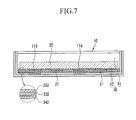
FIG. 7 is a cross-sectional view taken along line VII-VII inFIG. 2 . With reference toFIG. 7 , as thePCM 20 is attached to thesecond portion 32, theprotection elements 21 protruded from thePCM 20 are buried in thesecond portion 32. - The buffer portion 33 forms the majority of the thickness of the insulating
member 30, allowing theprotection elements 21 to be buried therein, and absorbing vibration of an impact transferred from thebare cell 10 or theend portion 124 to thePCM 20. For example, the buffer portion 33 may be made of an expandable cushion material, e.g., an urethane foam. - With reference back to
FIG. 4 , thefirst portion 31 of thefirst buffer portion 331 may be formed to have a thickness t1, and thesecond portion 32 of thesecond buffer portion 332 may be formed to have a second thickness t2 greater than the first thickness t1. As the second thickness t2 of thesecond portion 32 of thesecond buffer portion 332 is increased, thePCM 20 and theprotection elements 21 can be further effectively protected against vibration and impact. Also, the first andsecond portions second buffer portions member 30 may be more easily fabricated. -
FIG. 8 is a partial sectional view of a rechargeable battery pack according to a second embodiment of the present invention. With reference toFIG. 8 , in comparison to the first embodiment, an insulatingmember 230 of the second embodiment does not have a insulating layer on thefirst surface portion 125. - The
first portion 231 includes thefirst buffer portion 331 and the firstadhesive layer 341. In addition, thesecond portion 232 includes thefirst buffer portion 332, the secondadhesive layer 342 and the second insulatinglayer 352. - Thus, the adhesive layer 34 of the insulating
member 230 attaches the first andsecond buffer portions first surface portion 125 and thesecond surface portion 126 respectively. Here, the first andsecond buffer portions member 230. - The insulating
layer 352 electrically insulates thePCM 20 from thesecond surface portion 126. - The plane of the
PCM 20 on which the protection elements are mounted is positioned on thesecond surface portion 126, and an end portion of the PCM may not be attached to thefirst surface portion 125 or may be spaced apart from thefirst surface portion 125. -
FIG. 9 is a partial sectional view of a rechargeable battery pack according to a third embodiment of the present invention. With reference toFIG. 9 , in comparison to the first embodiment, an insulatingmember 330 of the third embodiment further includes a thirdadhesive layer 343 positioned on the second insulatinglayer 352. - That is, the
first portion 31 includes thefirst buffer portion 331, the firstadhesive layer 341 and the first insulatinglayer 351. In addition, thesecond portion 32 includes thesecond buffer portion 332, the secondadhesive layer 342, the second insulatinglayer 352 and the thirdadhesive layer 343. - In this case, the first and
second buffer portions second portions - Here, the third
adhesive layer 343 is formed only on the second insulatinglayer 352 of thesecond portion 32. - Thus, the first and second
adhesive layers member 330 attach the first andsecond buffer portions first surface portion 125 and thesecond surface portion 126 respectively. - The third
adhesive layer 343 attaches thePCM 20 to the second insulatinglayer 352 of thesecond surface portion 126. - Accordingly, the
PCM 20 may be stably position on the second insulatinglayer 352 of thesecond surface portion 126 and electrically insulated by the insulatingmember 330. -
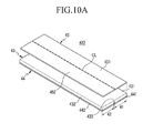
FIG. 10(a) is an exploded perspective view of the insulating member, andFIG. 10(b) is a perspective view showing a bent state of the insulating member according to a third embodiment of the present invention. - Referring to
FIG. 10(a) , an insulatingmember 430 has an area facing theend portion 124 of thebare cell 10. In addition, the insulatingmember 430 includes thefirst portion 41 facing thefirst surface portion 125, thesecond portion 42 facing thesecond surface portion 126, athird portion 433 connecting the first andsecond buffer portions second portions - The
buffer portion 43 is partially cut through along with the perforated line CL. Accordingly, thefirst buffer portion 431 is positioned on thefirst portion 41. Thesecond buffer portion 432 is positioned on thesecond portion 42. Thethird portion 433 connects the first andsecond buffer portions - Accordingly, the adhesive layer 444 includes a first
adhesive layer 441 positioned on thefirst buffer portion 431 and a secondadhesive layer 442 positioned on thesecond buffer portion 432. - That is, the adhesive layer 444 is not formed or positioned on the
third portion 433. - Accordingly, a resilience force on the insulating member is reduced since the first and
second portions third portion 433. - In addition, the first and second insulating
layers second buffer portions third portion 433 connects the insulatinglayer 45. - While this invention has been described in connection with what is presently considered to be practical embodiments, it is to be understood that the invention is not limited to the disclosed embodiments, but, on the contrary, is intended to cover various modifications and equivalent arrangements included within the scope of the appended claims.
Claims (15)
- A rechargeable battery including:a bare cell (10) having an end portion (124) including a first surface portion (125) and a second surface portion (126) projecting from the first surface portion;a protection circuit module (PCM) electrically connected to the bare cell;an insulating member having a first portion (31) attached to the first surface portion and a second portion (32) attached to the second surface portion, and a hinge portion connecting the first and second portions, wherein the hinge portion comprises a line of weakness configured to allow the insulating member to bend at the hinge portion for attachment to the end portion.
- A rechargeable battery according to claim 1, wherein the first surface projects at right angles from the second surface.
- A rechargeable battery according to claim 1 or 2, wherein the PCM is attached to the insulating member.
- A rechargeable battery according to claim 3, wherein the PCM is attached to the second portion of the insulating member.
- A rechargeable battery according to any one of the preceding claims, wherein the first portion and the second portion include a first buffer portion and a second buffer portion respectively, each formed of a cushion material.
- A rechargeable battery according to claim 5, further including a third buffer portion connecting the first and second buffer portions, the third buffer portion having a reduced thickness compared to the first and second buffer portions.
- A rechargeable battery according to claim 5, wherein the first and second buffer portions are separate.
- A rechargeable battery according to any one of the preceding claims, wherein the second portion includes a first adhesive layer (34) on a first side attaching the second portion to the second surface portion and a second adhesive layer (35) on an opposite side attaching the second adhesive portion to the PCM.
- A rechargeable battery according to any one of the preceding claims, wherein the first portion includes a first adhesive layer on a first side attaching the first portion to the first surface portion.
- A rechargeable battery according to claim 9, wherein the first portion does not have an adhesive layer on an opposite side facing the PCM.
- A rechargeable battery according to claim 9, wherein the first portion includes a second adhesive layer on an opposite side attaching the first portion to the PCM.
- A rechargeable battery according to any one of the preceding claims, wherein the insulating member includes an insulating sheet (36) connecting the first portion and the second portion and forming the hinge portion.
- A rechargeable battery according to claim 12, wherein the insulating sheet is disposed on the surfaces of the first and second portions of the insulating member facing the PCM.
- A rechargeable battery according to claim 12 or 13 when dependent on claim 8, wherein the second adhesive layer is disposed on the insulating sheet on the second portion.
- A rechargeable battery according to any one of the preceding claims, wherein the hinge portion comprises a perforated line formed on the insulating member.
Applications Claiming Priority (2)
| Application Number | Priority Date | Filing Date | Title |
|---|---|---|---|
| US201261657151P | 2012-06-08 | 2012-06-08 | |
| US13/792,520 US9196894B2 (en) | 2012-06-08 | 2013-03-11 | Rechargeable battery pack |
Publications (2)
| Publication Number | Publication Date |
|---|---|
| EP2672543A1 true EP2672543A1 (en) | 2013-12-11 |
| EP2672543B1 EP2672543B1 (en) | 2016-06-08 |
Family
ID=48095730
Family Applications (1)
| Application Number | Title | Priority Date | Filing Date |
|---|---|---|---|
| EP13163987.4A Active EP2672543B1 (en) | 2012-06-08 | 2013-04-16 | Rechargeable battery pack |
Country Status (4)
| Country | Link |
|---|---|
| US (1) | US9196894B2 (en) |
| EP (1) | EP2672543B1 (en) |
| KR (1) | KR20130138110A (en) |
| CN (1) | CN103490034B (en) |
Families Citing this family (10)
| Publication number | Priority date | Publication date | Assignee | Title |
|---|---|---|---|---|
| KR101699855B1 (en) * | 2013-09-30 | 2017-01-25 | 주식회사 엘지화학 | Battery Pack Having Electric Insulating Member |
| KR102373583B1 (en) * | 2015-07-07 | 2022-03-10 | 에스케이온 주식회사 | Pouch type secondary cell |
| KR102270512B1 (en) * | 2016-07-12 | 2021-06-29 | 삼성에스디아이 주식회사 | Rechargeable battery |
| KR102183995B1 (en) | 2016-10-31 | 2020-11-27 | 삼성에스디아이 주식회사 | Battery pack |
| KR102331065B1 (en) * | 2017-04-06 | 2021-11-25 | 삼성에스디아이 주식회사 | Battery pack |
| KR102760183B1 (en) * | 2019-08-09 | 2025-02-03 | 주식회사 엘지에너지솔루션 | Electrochemical Device Comprising Short Circuit Induction Member and Method of Evaluation for Battery Safety Using Thereof |
| EP4489215A4 (en) * | 2022-03-24 | 2025-10-01 | Ningde Amperex Technology Ltd | BATTERY AND ELECTRONIC DEVICE |
| WO2024098423A1 (en) * | 2022-11-11 | 2024-05-16 | 深圳海润新能源科技有限公司 | Energy storage device and electric device |
| US20240322289A1 (en) * | 2023-03-26 | 2024-09-26 | Samsung Sdi Co., Ltd | Portable battery pack having improved heat dissipation structure |
| KR20250140747A (en) * | 2024-03-19 | 2025-09-26 | 삼성에스디아이 주식회사 | Battery Pack |
Citations (3)
| Publication number | Priority date | Publication date | Assignee | Title |
|---|---|---|---|---|
| US20060099503A1 (en) * | 2004-09-24 | 2006-05-11 | Lee Hyung B | Lithium polymer battery and method for manufacturing the same |
| EP1717881A1 (en) * | 2005-04-26 | 2006-11-02 | Samsung SDI Co., Ltd. | Polymer battery pack and manufacturing method of the same |
| US20090087693A1 (en) * | 2007-09-28 | 2009-04-02 | Heongsin Kim | Secondary battery |
Family Cites Families (3)
| Publication number | Priority date | Publication date | Assignee | Title |
|---|---|---|---|---|
| KR100561284B1 (en) | 2003-12-26 | 2006-03-15 | 삼성에스디아이 주식회사 | Pouch Type Lithium Secondary Battery |
| KR100922469B1 (en) | 2007-09-21 | 2009-10-21 | 삼성에스디아이 주식회사 | Battery pack |
| KR101059756B1 (en) | 2009-05-08 | 2011-08-26 | 주식회사 엘지화학 | New rechargeable battery pack |
-
2013
- 2013-03-11 US US13/792,520 patent/US9196894B2/en active Active
- 2013-04-16 EP EP13163987.4A patent/EP2672543B1/en active Active
- 2013-05-24 KR KR1020130059311A patent/KR20130138110A/en not_active Ceased
- 2013-06-05 CN CN201310220411.7A patent/CN103490034B/en active Active
Patent Citations (3)
| Publication number | Priority date | Publication date | Assignee | Title |
|---|---|---|---|---|
| US20060099503A1 (en) * | 2004-09-24 | 2006-05-11 | Lee Hyung B | Lithium polymer battery and method for manufacturing the same |
| EP1717881A1 (en) * | 2005-04-26 | 2006-11-02 | Samsung SDI Co., Ltd. | Polymer battery pack and manufacturing method of the same |
| US20090087693A1 (en) * | 2007-09-28 | 2009-04-02 | Heongsin Kim | Secondary battery |
Also Published As
| Publication number | Publication date |
|---|---|
| KR20130138110A (en) | 2013-12-18 |
| CN103490034A (en) | 2014-01-01 |
| US9196894B2 (en) | 2015-11-24 |
| EP2672543B1 (en) | 2016-06-08 |
| US20130330575A1 (en) | 2013-12-12 |
| CN103490034B (en) | 2017-03-01 |
Similar Documents
| Publication | Publication Date | Title |
|---|---|---|
| EP2672543B1 (en) | Rechargeable battery pack | |
| EP2838135B1 (en) | Rechargeable battery pack | |
| US9083040B2 (en) | Rechargeable battery pack | |
| EP2843750B1 (en) | Rechargeable battery pack | |
| JP6399688B2 (en) | Battery pack | |
| CN103972461B (en) | Rechargeable battery bag | |
| US9786958B2 (en) | Rechargeable battery with temperature-protecting element | |
| KR101885908B1 (en) | Rechargeable battery pack | |
| US12034128B2 (en) | Battery pack | |
| US20230299431A1 (en) | Battery cell, battery module, and battery pack including the same | |
| EP2680337B1 (en) | Rechargeable battery | |
| KR20160013758A (en) | Battery pack | |
| KR102483883B1 (en) | Rechargeable battery | |
| US12627009B2 (en) | Secondary battery | |
| US9123933B2 (en) | Rechargeable battery pack | |
| EP2854195A1 (en) | Batterypack with protective circuit module | |
| JP6288721B2 (en) | Assembled battery | |
| US20140255731A1 (en) | Rechargeable battery pack | |
| JP2025517191A (en) | Impact-resistant battery pack | |
| JP2013258093A (en) | Battery pack | |
| JP2018200761A (en) | Battery pack and electric power unit including the same and manufacturing method of battery pack |
Legal Events
| Date | Code | Title | Description |
|---|---|---|---|
| PUAI | Public reference made under article 153(3) epc to a published international application that has entered the european phase |
Free format text: ORIGINAL CODE: 0009012 |
|
| AK | Designated contracting states |
Kind code of ref document: A1 Designated state(s): AL AT BE BG CH CY CZ DE DK EE ES FI FR GB GR HR HU IE IS IT LI LT LU LV MC MK MT NL NO PL PT RO RS SE SI SK SM TR |
|
| AX | Request for extension of the european patent |
Extension state: BA ME |
|
| 17P | Request for examination filed |
Effective date: 20140611 |
|
| RBV | Designated contracting states (corrected) |
Designated state(s): AL AT BE BG CH CY CZ DE DK EE ES FI FR GB GR HR HU IE IS IT LI LT LU LV MC MK MT NL NO PL PT RO RS SE SI SK SM TR |
|
| REG | Reference to a national code |
Ref country code: DE Ref legal event code: R079 Ref document number: 602013008318 Country of ref document: DE Free format text: PREVIOUS MAIN CLASS: H01M0002020000 Ipc: H01M0002340000 |
|
| GRAP | Despatch of communication of intention to grant a patent |
Free format text: ORIGINAL CODE: EPIDOSNIGR1 |
|
| RIC1 | Information provided on ipc code assigned before grant |
Ipc: H01M 10/04 20060101ALI20151202BHEP Ipc: H01M 2/06 20060101ALI20151202BHEP Ipc: H01M 2/34 20060101AFI20151202BHEP Ipc: H01M 2/02 20060101ALI20151202BHEP Ipc: H01M 2/22 20060101ALI20151202BHEP Ipc: H01M 10/42 20060101ALI20151202BHEP |
|
| INTG | Intention to grant announced |
Effective date: 20151223 |
|
| GRAS | Grant fee paid |
Free format text: ORIGINAL CODE: EPIDOSNIGR3 |
|
| GRAA | (expected) grant |
Free format text: ORIGINAL CODE: 0009210 |
|
| AK | Designated contracting states |
Kind code of ref document: B1 Designated state(s): AL AT BE BG CH CY CZ DE DK EE ES FI FR GB GR HR HU IE IS IT LI LT LU LV MC MK MT NL NO PL PT RO RS SE SI SK SM TR |
|
| REG | Reference to a national code |
Ref country code: GB Ref legal event code: FG4D |
|
| REG | Reference to a national code |
Ref country code: CH Ref legal event code: EP |
|
| REG | Reference to a national code |
Ref country code: IE Ref legal event code: FG4D |
|
| REG | Reference to a national code |
Ref country code: AT Ref legal event code: REF Ref document number: 805790 Country of ref document: AT Kind code of ref document: T Effective date: 20160715 |
|
| REG | Reference to a national code |
Ref country code: DE Ref legal event code: R096 Ref document number: 602013008318 Country of ref document: DE |
|
| REG | Reference to a national code |
Ref country code: LT Ref legal event code: MG4D |
|
| REG | Reference to a national code |
Ref country code: NL Ref legal event code: MP Effective date: 20160608 |
|
| PG25 | Lapsed in a contracting state [announced via postgrant information from national office to epo] |
Ref country code: LT Free format text: LAPSE BECAUSE OF FAILURE TO SUBMIT A TRANSLATION OF THE DESCRIPTION OR TO PAY THE FEE WITHIN THE PRESCRIBED TIME-LIMIT Effective date: 20160608 Ref country code: FI Free format text: LAPSE BECAUSE OF FAILURE TO SUBMIT A TRANSLATION OF THE DESCRIPTION OR TO PAY THE FEE WITHIN THE PRESCRIBED TIME-LIMIT Effective date: 20160608 Ref country code: NO Free format text: LAPSE BECAUSE OF FAILURE TO SUBMIT A TRANSLATION OF THE DESCRIPTION OR TO PAY THE FEE WITHIN THE PRESCRIBED TIME-LIMIT Effective date: 20160908 |
|
| REG | Reference to a national code |
Ref country code: AT Ref legal event code: MK05 Ref document number: 805790 Country of ref document: AT Kind code of ref document: T Effective date: 20160608 |
|
| PG25 | Lapsed in a contracting state [announced via postgrant information from national office to epo] |
Ref country code: LV Free format text: LAPSE BECAUSE OF FAILURE TO SUBMIT A TRANSLATION OF THE DESCRIPTION OR TO PAY THE FEE WITHIN THE PRESCRIBED TIME-LIMIT Effective date: 20160608 Ref country code: RS Free format text: LAPSE BECAUSE OF FAILURE TO SUBMIT A TRANSLATION OF THE DESCRIPTION OR TO PAY THE FEE WITHIN THE PRESCRIBED TIME-LIMIT Effective date: 20160608 Ref country code: HR Free format text: LAPSE BECAUSE OF FAILURE TO SUBMIT A TRANSLATION OF THE DESCRIPTION OR TO PAY THE FEE WITHIN THE PRESCRIBED TIME-LIMIT Effective date: 20160608 Ref country code: ES Free format text: LAPSE BECAUSE OF FAILURE TO SUBMIT A TRANSLATION OF THE DESCRIPTION OR TO PAY THE FEE WITHIN THE PRESCRIBED TIME-LIMIT Effective date: 20160608 Ref country code: NL Free format text: LAPSE BECAUSE OF FAILURE TO SUBMIT A TRANSLATION OF THE DESCRIPTION OR TO PAY THE FEE WITHIN THE PRESCRIBED TIME-LIMIT Effective date: 20160608 Ref country code: SE Free format text: LAPSE BECAUSE OF FAILURE TO SUBMIT A TRANSLATION OF THE DESCRIPTION OR TO PAY THE FEE WITHIN THE PRESCRIBED TIME-LIMIT Effective date: 20160608 Ref country code: GR Free format text: LAPSE BECAUSE OF FAILURE TO SUBMIT A TRANSLATION OF THE DESCRIPTION OR TO PAY THE FEE WITHIN THE PRESCRIBED TIME-LIMIT Effective date: 20160909 |
|
| PG25 | Lapsed in a contracting state [announced via postgrant information from national office to epo] |
Ref country code: IT Free format text: LAPSE BECAUSE OF FAILURE TO SUBMIT A TRANSLATION OF THE DESCRIPTION OR TO PAY THE FEE WITHIN THE PRESCRIBED TIME-LIMIT Effective date: 20160608 Ref country code: SK Free format text: LAPSE BECAUSE OF FAILURE TO SUBMIT A TRANSLATION OF THE DESCRIPTION OR TO PAY THE FEE WITHIN THE PRESCRIBED TIME-LIMIT Effective date: 20160608 Ref country code: EE Free format text: LAPSE BECAUSE OF FAILURE TO SUBMIT A TRANSLATION OF THE DESCRIPTION OR TO PAY THE FEE WITHIN THE PRESCRIBED TIME-LIMIT Effective date: 20160608 Ref country code: IS Free format text: LAPSE BECAUSE OF FAILURE TO SUBMIT A TRANSLATION OF THE DESCRIPTION OR TO PAY THE FEE WITHIN THE PRESCRIBED TIME-LIMIT Effective date: 20161008 Ref country code: CZ Free format text: LAPSE BECAUSE OF FAILURE TO SUBMIT A TRANSLATION OF THE DESCRIPTION OR TO PAY THE FEE WITHIN THE PRESCRIBED TIME-LIMIT Effective date: 20160608 Ref country code: RO Free format text: LAPSE BECAUSE OF FAILURE TO SUBMIT A TRANSLATION OF THE DESCRIPTION OR TO PAY THE FEE WITHIN THE PRESCRIBED TIME-LIMIT Effective date: 20160608 |
|
| PG25 | Lapsed in a contracting state [announced via postgrant information from national office to epo] |
Ref country code: PT Free format text: LAPSE BECAUSE OF FAILURE TO SUBMIT A TRANSLATION OF THE DESCRIPTION OR TO PAY THE FEE WITHIN THE PRESCRIBED TIME-LIMIT Effective date: 20161010 Ref country code: SM Free format text: LAPSE BECAUSE OF FAILURE TO SUBMIT A TRANSLATION OF THE DESCRIPTION OR TO PAY THE FEE WITHIN THE PRESCRIBED TIME-LIMIT Effective date: 20160608 Ref country code: AT Free format text: LAPSE BECAUSE OF FAILURE TO SUBMIT A TRANSLATION OF THE DESCRIPTION OR TO PAY THE FEE WITHIN THE PRESCRIBED TIME-LIMIT Effective date: 20160608 Ref country code: PL Free format text: LAPSE BECAUSE OF FAILURE TO SUBMIT A TRANSLATION OF THE DESCRIPTION OR TO PAY THE FEE WITHIN THE PRESCRIBED TIME-LIMIT Effective date: 20160608 Ref country code: BE Free format text: LAPSE BECAUSE OF FAILURE TO SUBMIT A TRANSLATION OF THE DESCRIPTION OR TO PAY THE FEE WITHIN THE PRESCRIBED TIME-LIMIT Effective date: 20160608 |
|
| REG | Reference to a national code |
Ref country code: DE Ref legal event code: R097 Ref document number: 602013008318 Country of ref document: DE |
|
| REG | Reference to a national code |
Ref country code: FR Ref legal event code: PLFP Year of fee payment: 5 |
|
| PLBE | No opposition filed within time limit |
Free format text: ORIGINAL CODE: 0009261 |
|
| STAA | Information on the status of an ep patent application or granted ep patent |
Free format text: STATUS: NO OPPOSITION FILED WITHIN TIME LIMIT |
|
| 26N | No opposition filed |
Effective date: 20170309 |
|
| PG25 | Lapsed in a contracting state [announced via postgrant information from national office to epo] |
Ref country code: DK Free format text: LAPSE BECAUSE OF FAILURE TO SUBMIT A TRANSLATION OF THE DESCRIPTION OR TO PAY THE FEE WITHIN THE PRESCRIBED TIME-LIMIT Effective date: 20160608 Ref country code: SI Free format text: LAPSE BECAUSE OF FAILURE TO SUBMIT A TRANSLATION OF THE DESCRIPTION OR TO PAY THE FEE WITHIN THE PRESCRIBED TIME-LIMIT Effective date: 20160608 |
|
| REG | Reference to a national code |
Ref country code: CH Ref legal event code: PL |
|
| REG | Reference to a national code |
Ref country code: IE Ref legal event code: MM4A |
|
| PG25 | Lapsed in a contracting state [announced via postgrant information from national office to epo] |
Ref country code: MC Free format text: LAPSE BECAUSE OF FAILURE TO SUBMIT A TRANSLATION OF THE DESCRIPTION OR TO PAY THE FEE WITHIN THE PRESCRIBED TIME-LIMIT Effective date: 20160608 |
|
| PG25 | Lapsed in a contracting state [announced via postgrant information from national office to epo] |
Ref country code: CH Free format text: LAPSE BECAUSE OF NON-PAYMENT OF DUE FEES Effective date: 20170430 Ref country code: LI Free format text: LAPSE BECAUSE OF NON-PAYMENT OF DUE FEES Effective date: 20170430 Ref country code: LU Free format text: LAPSE BECAUSE OF NON-PAYMENT OF DUE FEES Effective date: 20170416 |
|
| REG | Reference to a national code |
Ref country code: FR Ref legal event code: PLFP Year of fee payment: 6 |
|
| PG25 | Lapsed in a contracting state [announced via postgrant information from national office to epo] |
Ref country code: IE Free format text: LAPSE BECAUSE OF NON-PAYMENT OF DUE FEES Effective date: 20170416 |
|
| PG25 | Lapsed in a contracting state [announced via postgrant information from national office to epo] |
Ref country code: MT Free format text: LAPSE BECAUSE OF NON-PAYMENT OF DUE FEES Effective date: 20170416 |
|
| PG25 | Lapsed in a contracting state [announced via postgrant information from national office to epo] |
Ref country code: AL Free format text: LAPSE BECAUSE OF FAILURE TO SUBMIT A TRANSLATION OF THE DESCRIPTION OR TO PAY THE FEE WITHIN THE PRESCRIBED TIME-LIMIT Effective date: 20160608 |
|
| PG25 | Lapsed in a contracting state [announced via postgrant information from national office to epo] |
Ref country code: HU Free format text: LAPSE BECAUSE OF FAILURE TO SUBMIT A TRANSLATION OF THE DESCRIPTION OR TO PAY THE FEE WITHIN THE PRESCRIBED TIME-LIMIT; INVALID AB INITIO Effective date: 20130416 |
|
| PG25 | Lapsed in a contracting state [announced via postgrant information from national office to epo] |
Ref country code: BG Free format text: LAPSE BECAUSE OF FAILURE TO SUBMIT A TRANSLATION OF THE DESCRIPTION OR TO PAY THE FEE WITHIN THE PRESCRIBED TIME-LIMIT Effective date: 20160608 |
|
| PG25 | Lapsed in a contracting state [announced via postgrant information from national office to epo] |
Ref country code: CY Free format text: LAPSE BECAUSE OF NON-PAYMENT OF DUE FEES Effective date: 20160608 |
|
| PG25 | Lapsed in a contracting state [announced via postgrant information from national office to epo] |
Ref country code: MK Free format text: LAPSE BECAUSE OF FAILURE TO SUBMIT A TRANSLATION OF THE DESCRIPTION OR TO PAY THE FEE WITHIN THE PRESCRIBED TIME-LIMIT Effective date: 20160608 |
|
| PG25 | Lapsed in a contracting state [announced via postgrant information from national office to epo] |
Ref country code: TR Free format text: LAPSE BECAUSE OF FAILURE TO SUBMIT A TRANSLATION OF THE DESCRIPTION OR TO PAY THE FEE WITHIN THE PRESCRIBED TIME-LIMIT Effective date: 20160608 |
|
| REG | Reference to a national code |
Ref country code: DE Ref legal event code: R079 Ref document number: 602013008318 Country of ref document: DE Free format text: PREVIOUS MAIN CLASS: H01M0002340000 Ipc: H01M0050572000 |
|
| P01 | Opt-out of the competence of the unified patent court (upc) registered |
Effective date: 20230528 |
|
| PGFP | Annual fee paid to national office [announced via postgrant information from national office to epo] |
Ref country code: DE Payment date: 20250408 Year of fee payment: 13 |
|
| PGFP | Annual fee paid to national office [announced via postgrant information from national office to epo] |
Ref country code: GB Payment date: 20250403 Year of fee payment: 13 |
|
| PGFP | Annual fee paid to national office [announced via postgrant information from national office to epo] |
Ref country code: FR Payment date: 20250409 Year of fee payment: 13 |