EP2672235A1 - Optical fiber characteristics measurement device and method - Google Patents
Optical fiber characteristics measurement device and method Download PDFInfo
- Publication number
- EP2672235A1 EP2672235A1 EP12742488.5A EP12742488A EP2672235A1 EP 2672235 A1 EP2672235 A1 EP 2672235A1 EP 12742488 A EP12742488 A EP 12742488A EP 2672235 A1 EP2672235 A1 EP 2672235A1
- Authority
- EP
- European Patent Office
- Prior art keywords
- light
- optical fiber
- detection signal
- measurement device
- period
- Prior art date
- Legal status (The legal status is an assumption and is not a legal conclusion. Google has not performed a legal analysis and makes no representation as to the accuracy of the status listed.)
- Granted
Links
Images



Classifications
-
- G—PHYSICS
- G01—MEASURING; TESTING
- G01M—TESTING STATIC OR DYNAMIC BALANCE OF MACHINES OR STRUCTURES; TESTING OF STRUCTURES OR APPARATUS, NOT OTHERWISE PROVIDED FOR
- G01M11/00—Testing of optical apparatus; Testing structures by optical methods not otherwise provided for
- G01M11/30—Testing of optical devices, constituted by fibre optics or optical waveguides
- G01M11/33—Testing of optical devices, constituted by fibre optics or optical waveguides with a light emitter being disposed at one fibre or waveguide end-face, and a light receiver at the other end-face
-
- G—PHYSICS
- G01—MEASURING; TESTING
- G01M—TESTING STATIC OR DYNAMIC BALANCE OF MACHINES OR STRUCTURES; TESTING OF STRUCTURES OR APPARATUS, NOT OTHERWISE PROVIDED FOR
- G01M11/00—Testing of optical apparatus; Testing structures by optical methods not otherwise provided for
- G01M11/30—Testing of optical devices, constituted by fibre optics or optical waveguides
- G01M11/39—Testing of optical devices, constituted by fibre optics or optical waveguides in which light is projected from both sides of the fiber or waveguide end-face
-
- G—PHYSICS
- G01—MEASURING; TESTING
- G01D—MEASURING NOT SPECIALLY ADAPTED FOR A SPECIFIC VARIABLE; ARRANGEMENTS FOR MEASURING TWO OR MORE VARIABLES NOT COVERED IN A SINGLE OTHER SUBCLASS; TARIFF METERING APPARATUS; MEASURING OR TESTING NOT OTHERWISE PROVIDED FOR
- G01D5/00—Mechanical means for transferring the output of a sensing member; Means for converting the output of a sensing member to another variable where the form or nature of the sensing member does not constrain the means for converting; Transducers not specially adapted for a specific variable
- G01D5/26—Mechanical means for transferring the output of a sensing member; Means for converting the output of a sensing member to another variable where the form or nature of the sensing member does not constrain the means for converting; Transducers not specially adapted for a specific variable characterised by optical transfer means, i.e. using infrared, visible, or ultraviolet light
- G01D5/32—Mechanical means for transferring the output of a sensing member; Means for converting the output of a sensing member to another variable where the form or nature of the sensing member does not constrain the means for converting; Transducers not specially adapted for a specific variable characterised by optical transfer means, i.e. using infrared, visible, or ultraviolet light with attenuation or whole or partial obturation of beams of light
- G01D5/34—Mechanical means for transferring the output of a sensing member; Means for converting the output of a sensing member to another variable where the form or nature of the sensing member does not constrain the means for converting; Transducers not specially adapted for a specific variable characterised by optical transfer means, i.e. using infrared, visible, or ultraviolet light with attenuation or whole or partial obturation of beams of light the beams of light being detected by photocells
- G01D5/353—Mechanical means for transferring the output of a sensing member; Means for converting the output of a sensing member to another variable where the form or nature of the sensing member does not constrain the means for converting; Transducers not specially adapted for a specific variable characterised by optical transfer means, i.e. using infrared, visible, or ultraviolet light with attenuation or whole or partial obturation of beams of light the beams of light being detected by photocells influencing the transmission properties of an optical fibre
- G01D5/35338—Mechanical means for transferring the output of a sensing member; Means for converting the output of a sensing member to another variable where the form or nature of the sensing member does not constrain the means for converting; Transducers not specially adapted for a specific variable characterised by optical transfer means, i.e. using infrared, visible, or ultraviolet light with attenuation or whole or partial obturation of beams of light the beams of light being detected by photocells influencing the transmission properties of an optical fibre using other arrangements than interferometer arrangements
- G01D5/35341—Sensor working in transmission
- G01D5/35348—Sensor working in transmission using stimulated emission to detect the measured quantity
Definitions
- the present invention relates to an optical fiber characteristics measurement device and method.
- Priority is claimed on Japanese Patent Application No. 2011-018951, filed on January 31, 2011 , the content of which is incorporated herein by reference.
- An optical fiber characteristics measurement device is a device that inputs continuous light or pulse light into an optical fiber, receives scattered light or reflected light that occurs within the optical fiber, and measures temperature distribution, strain distribution, and other characteristics in the longitudinal direction of the optical fiber.
- the optical fiber characteristics measurement device because the received scattered light or reflected light varies in response to physical quantities (for example, temperature and strain) that influence the optical fiber, the optical fiber itself is used as a sensor.
- Patent Document 1 discloses an optical fiber characteristics measurement device in which frequency-modulated continuous light (pump light and probe light) is sent into each respective end of the optical fiber, thereby forming periodic correlation peaks between the pump light and the probe light along the optical fiber, a characteristic of the optical fiber being measured by utilizing the property that the probe light is amplified by the stimulated Brillouin scattering only a positions of the correlation peaks.
- This optical fiber characteristics measurement device by receiving amplified probe light at each position while varying the correlation peak positions within the optical fiber, can measure the characteristics of an optical fiber in the longitudinal direction.
- Patent Document 2 discloses an optical fiber characteristics measurement device in which frequency-modulated continuous light (probe light) and pulse light (pump light) are sent into one and into the other end of an optical fiber, causing successive correlation peaks in accordance with the position of the pump light that propagates within the optical fiber, so as to obtain only light (stimulated Brillouin scattered light) in the vicinity of a measurement point of the light exiting from the optical fiber, so as to measure the characteristics of the optical fiber at the measurement point.
- This optical fiber characteristics measurement device adjusts the modulation frequency of the probe light and the pump light and the timing of receiving the light exiting from the optical fiber, so as to move the measurement point, thereby enabling measurement of the characteristics at an arbitrary position along the longitudinal direction of the optical fiber.
- the optical fiber characteristics measurement device disclosed in Patent Document 2 has a timing adjuster in the front end of the optical detector that receives light exiting from the optical fiber and, by separating out light exiting from the optical fiber by the timing adjuster, receives at the optical detector only light from the vicinity of the measurement point.
- the above-noted optical switch can switch between the on state (state that passes light) and the off state (state that blocks light) at a high speed, and can, for example, also separate out light exiting from the optical fiber with a time interval of approximately several nanoseconds.
- an optical switch such as this is used as a timing adjuster, an optical fiber characteristics measurement device having a high spatial resolution of approximately 1 cm can be achieved.
- the above-noted optical switch has a large insertion loss, has polarization dependency, and is expensive. For this reason, it can be envisioned that the following problems might occur in the future in improving the spatial resolution and reducing the cost of an optical fiber characteristics measurement device.
- the signal level (intensity of the received light signal) obtained by an optical fiber characteristics measurement device decreases as the spatial resolution increases, if the spatial resolution is made high, the S/N ratio (signal-to-noise ratio) inevitably decreases. Because the above-described optical switch has a high insertion loss of approximately 3 to 5 dB and further decreases the S/N ratio, an attempt to improve the spatial resolution of the optical fiber characteristics measurement device has the problem of causing a worsening of the measurement accuracy.
- the above-noted optical switch has polarization dependency, whereby the intensity of the passed light varies in accordance with the polarization direction of the incident light and, according to this characteristic, the insertion loss of the optical switch also varies in accordance with the polarization direction of the incident light.
- the above-noted optical switch often has a control device that performs feedback control of a bias voltage for the purpose of preventing temperature variations and time variations of the operating characteristics, this not only makes the constitution complex, but also, with a control signal for feedback control being superimposed on the light exiting from the optical fiber, has the problem of being a factor in lowering the S/N ratio. Also, because the above-noted optical switch is itself expensive, there is a problem of a disadvantage in terms of trying to reduce the cost of the optical fiber characteristics measurement device.
- the present invention was made in consideration of the above-noted situation, and has an object to provide an optical fiber characteristics measurement device and method that, without leading to a worsening of measurement accuracy, or a worsening of stability and reproducibility, can improve the spatial resolution and reduce the cost.
- an optical fiber characteristics measurement device (1,2) in accordance with the present invention may include: a light source (11) configured to emit a laser light modulated by a prescribed modulation frequency; a light inputting means (12, 13, 15, 16) configured to cause the laser light from the light source to enter one end and another end of an optical fiber (14) as continuous light (L1) and pulse light (L2), respectively; and a light detector (17) configured to detect light exiting from the optical fiber, and to measure a characteristic of the optical fiber by using a detection result of the light detector, characterized in that the optical fiber characteristics measurement device comprises: a synchronous detection device (18, 30) configured to separate out, of a detection signal (D1) output from the light detector, a detection signal obtained by detecting light in the vicinity of a measurement point set in the optical fiber, and to detect synchronously a detection signal separated out by using a synchronization signal (SY, SY1) having a prescribed period.
- a synchronous detection device (18, 30) configured to separate out, of a detection signal (D1) output
- the following steps are performed; separating out a detection signal obtaining by detecting light in the vicinity of the measurement point set in an optical fiber from a detection signal output from a light detector; and synchronously detecting the separated out detection signal using a synchronization signal having a prescribed period.
- the synchronous detection device may include: a timing adjuster (18a) configured to separate out by passing, of the detection signal output from the light detector, a detection signal obtained by detecting light in the vicinity of a measurement point set in the optical fiber; and a synchronous detector (18b) configured to use the synchronization signal to synchronously detect the detection signal passed through the timing adjuster.
- an operating period of the timing adjuster may be a period that is one-half a period of the synchronization signal.
- the synchronous detection device may include: an inverter (21 b) configured to output an inverted signal that is the detection signal output from the light detector, with the polarity thereof inverted; a non-inverter (21a) configured to output a non-inverted signal that is the detection signal output from the light detector, with the polarity thereof not inverted; a switching unit (31) configured to separate out by alternately outputting the inverted signal output from the inverter and the non-inverted signal output from the non-inverter at a timing of the output from the light detector of a detection signal obtained by detecting light in the vicinity of the measurement point set in the optical fiber; and a lowpass filter (24) configured to filter a signal (S1) output from the switching unit.
- a period of the pulse light input to the other end of the optical fiber may be set to at least two times an amount of time required for the pulse light to make a round trip from one end to the other end of the optical fiber, and a period of the synchronization signal may be the same as the period of the pulse light being input to the other end of the optical fiber.
- a method of measuring a characteristics of an optical fiber in accordance with the present invention may include: inputting laser light modulated by a prescribed modulation frequency to one end and another end of the optical fiber (14) as continuous light (L1) and pulse light (L2), respectively; and detecting with a light detector (17) light exiting from the optical fiber, characterized in that the method comprises: separating out, of a detection signal output from the light detector, a detection signal obtained by detecting light in the vicinity of a measurement point set in the optical fiber; and synchronously detecting a detection signal separated out by using a synchronization signal having a prescribed period.
- the present invention by separating out a detection signal obtaining by detecting light in the vicinity of the measurement point set in an optical fiber from a detection signal output from a light detector, and synchronously detecting the separated out detection signal using a synchronization signal having a prescribed period, it is possible to achieve the effect of improving the spatial resolution and reducing cost, without leading to a worsening of measurement accuracy or a worsening of stability and reproducibility.
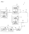
- FIG. 1 is a block diagram illustrating the constitution of the main part of an optical fiber characteristics measurement device in accordance with a first preferred embodiment of the present invention.
- the optical fiber characteristics measurement device 1 of the first preferred embodiment has a light source 11, an optical splitter 12 (light inputting means), an optical modulator 13 (light inputting means), an optical fiber 14, a pulse modulator 15 (light inputting means), a directional coupler 16 (light inputting means), a light detector 17, and a synchronous detection device 18, and measures the characteristics (for example temperature distribution or strain distribution) of the optical fiber 14 in the longitudinal direction.
- the light source 11 has a semiconductor laser 11a and a signal generator 11b, and emits laser light modulated by a prescribed modulation frequency f m .
- the semiconductor laser 11a that is used can be, for example, an MQW DFB (multi-quantum well, distributed feedback) laser diode that is compact and emits laser light having a narrow spectral width.
- the signal generator 11b outputs to the semiconductor laser 11a a sinewave signal (modulation signal) that frequency modulates the laser light exiting from the semiconductor laser 11a by the modulation frequency f m .
- the optical splitter 12 splits the laser light exiting from the light source 11 into two, for example, with a 1:1 intensity ratio.
- the optical modulator 13 has a microwave generator 13a and an SSB (single sideband) optical modulator 13b, and modulates (shifts the light frequency of) one of the laser lights split by the optical splitter 12 to generate a sideband (single sideband) with respect to the center frequency of the laser light.
- the single sideband on the low-frequency side is taken as the output from the optical modulator 13.
- the microwave generator 13a outputs a microwave signal having the frequency of the frequency shift imparted to one of the laser lights split by the optical splitter 12.
- the SSB optical modulator 13b generates a single sideband signal having a frequency difference with respect to the center frequency of the input light that is equal to the frequency of the microwave signal output from the microwave generator 13a.
- the frequency of the microwave signal output from the microwave generator 13a is variable.
- the light modulated by the optical modulator 13 is input as the probe light L1 (continuous light) into the optical fiber 14 from one end thereof.
- the pulse modulator 15 has a signal generator 15a and a light intensity modulator 15b, and generates a pulse light by making the other laser light split by the optical splitter 12 into a pulse.
- the signal generator 15a outputs a timing signal that establishes the timing of making the laser light into a pulse light.
- the light intensity modulator 15b is, for example, an EO (electro-optical) switch, which forms the laser light from the optical splitter 12 into a pulse light at a timing that is established by the timing signal output from the signal generator 15a.
- the pulse modulator 15 generates a pulse light with the period T given by the following Equation (1) and having a pulse width t pw given by the following Equation (2).
- Equation (1) and Equation (2) below L is the length of the optical fiber 14 (from one end to the other end), n is the refractive index of the optical fiber 14, c is the speed of light, d m is the interval of the correlation peaks formed in the optical fiber 14, and f m is the modulation frequency of the laser light exiting from the light source 11.
- the period T with which the pulse modulator 15 generates the pulse light is set to at least two times the amount of time required for the pulse light to make a round trip between one end and the other end of the optical fiber 14.
- the directional coupler 16 inputs laser light that has been made pulse light and output from the pulse modulator 15 as a pump light L2 into the optical fiber 14 from the other end thereof, and causes light (detection light L11) that includes a probe light L1 that has propagated through and exited from the other end of the optical fiber 14 to be incident toward the light detector 17.
- detection light L11 includes a probe light L1 that has propagated through and exited from the other end of the optical fiber 14 to be incident toward the light detector 17.
- the stimulated Brillouin scattering phenomenon occurring within the optical fiber 14 influences the intensity of the detection light L11.
- the light detector 17 has, for example, a high-sensitivity light-receiving element such as an avalanche photodiode, detects (receives) the above-noted detection light L11 (light exiting from the other end of the optical fiber 14 via the directional coupler 16), and outputs a detection signal D1.
- the light detector 17 has, in addition to the above-noted light-receiving element, a light wavelength filter, and selects and detects, of the probe light L1 from the detection light L11, the power of only light of the sideband on the low-frequency side.
- the above-noted light wavelength filter may be omitted.
- the synchronous detection device 18 has a timing adjuster 18a and a lock-in amplifier 18b (synchronous detector) and synchronously detects the detection signal D1 output from the light detector 17. Specifically, the synchronous detection device 18, of the detection signal D1 output from the light detector 17, detects and separates out light that includes stimulated Brillouin scattered light occurring at the measurement point set within the optical fiber 14 and in the vicinity thereof, and uses a synchronization signal SY (refer to FIG. 2 and FIG. 4 ) having a prescribed period to synchronously detect the separated out detection signal D2.
- a synchronization signal SY (refer to FIG. 2 and FIG. 4 ) having a prescribed period to synchronously detect the separated out detection signal D2.
- the timing adjuster 18a is implemented by, for example, an electrical switch (high-speed analog switch) that can switch at high speed between the on state (state in which the detection signal D1 is passed) and the off state (state in which the detection signal D1 is blocked).
- the timing adjuster 18a separates out the detection signal detected by passing a detection signal obtained by detecting light that includes stimulated Brillouin scattered light occurring at the measurement point set within the optical fiber 14 and in the vicinity thereof.
- the operating period of the timing adjuster 18a is set to a period that is one-half of the period of the above-noted synchronization signal SY.
- the timing adjuster 18a be capable of separating out the detection signal D1 with a time interval of approximately several nanoseconds and have low loss (for example, 1 dB or lower). If separation out with a time interval of approximately several nanoseconds is possible, a spatial resolution of 1 cm or better can be achieved, and if the loss is low, because there is no great reduction in the S/N ratio, measurement accuracy can be improved.
- an electrical switch as the timing adjuster 18a, compactness and low cost can be achieved. Additionally, because there is no polarization dependency as there is with an optical switch, there is no worsening of stability or reproducibility, and also it is possible to perform measurement over a wide temperature range from -40 to +80°C.
- the lock-in amplifier 18b uses the above-described synchronization signal SY to synchronously detect the detection signal D2 that has passed through the timing adjuster 18a (the detection signal separated out by the timing adjuster 18a).
- the period of the synchronization signal SY is set to a period that is the same as the period of the pump light L2 incident to the other end of the optical fiber 14 (at least two times the amount of time required for the pulse light to make a round trip between one end and the other end of the optical fiber 14).
- FIG. 2 is a block diagram illustrating the constitution of the main part of the lock-in amplifier of the optical fiber characteristics measurement device in accordance with the first preferred embodiment of the present invention.
- the lock-in amplifier 18b has a non-inverter 21a, an inverter 21b, a switching unit 22, a phase shifter 23, a lowpass filter 24, and a DC voltmeter 25, and uses the synchronization signal SY input to the synchronization signal input terminal Q2 to synchronously detect the detection signal D2 input to the signal input terminal Q1.
- the non-inverter 21a outputs the detection signal D2 input to the signal input terminal Q1 as is, without inverting the polarity thereof, and the inverter 21 b inverts and outputs the detection signal D2 input to the signal input terminal Q1. That is, the non-inverter 21a outputs a non-inverted signal that does not invert the polarity of the detection signal D2, and the inverter 21b outputs an inverted signal that inverts the polarity of the detection signal D2.
- the switching unit 22 has an input terminal a1, to which the output terminal of the non-inverter 21a is connected, an input terminal a2, to which the output terminal of the inverter 21b is connected, and an output terminal b1, to which the lowpass filter 24 is connected, and, based on the synchronization signal SY via the phase shifter 23, switches the output terminal b1 between the input terminals a1 and a2.
- the phase shifter 23 adjusts the phase by changing the phase of the synchronization signal SY input to the synchronization signal input terminal Q2.
- the lowpass filter 24 filters the output signal S1 output from the output terminal b1 of the switching unit 22. Specifically, it passes low-frequency components of the output signal S1 (frequency components lower than the cutoff frequency) and blocks high-frequency components that are above the cutoff frequency.
- the DC voltmeter 25 measures the voltage (DC voltage) value of the signal output from the lowpass filter 24.
- the optical splitter 12 splits laser light that is frequency modulated with the modulation frequency of f m when it is incident from the light source 11.
- One part of the laser light split by the optical splitter 12 is input to the optical modulator 13 and is modulated by the SSB optical modulator 13b, thereby generating a single sideband with respect to the center frequency of the laser light.
- the laser light (continuous light) having a signal sideband that has exited from the optical modulator 13 enters one end of the optical fiber 14 as the probe light L1.
- the other laser light split by the optical splitter 12 enters the pulse modulator 15 and becomes pulse light by intensity modulation by the light intensity modulator 15b.
- a pulse light having a pulse width given by the above-described Equation (2) is generated with a period T given by the above-described Equation (1).
- This pulse light via the directional coupler 16, enters the other end of the optical fiber 14 as the pump light L2.
- FIG. 3 shows the condition in which correlation peaks occur within the optical fiber 14 accompanying the advancing of the pump light.
- FIG. 3 shows the condition in which correlation peaks occur within the optical fiber 14 accompanying the advancing of the pump light.
- FIG. 3 to avoid having the drawing become complex, only the five correlation peaks P0 to P4 are shown.
- the correlation peaks P0 and P1 shown by broken lines are correlation peaks that have already been passed, and the correlation peaks P3 and P4 are correlation peaks that are going to be passed as the pump light L2 advances.
- the interval d m of the correlation peaks is given by the following Equation (3).
- d m c / n / 2 ⁇ f m That is, the interval d m of the correlation peaks can be changed by changing the modulation frequency f m in the light source 11, thereby moving the positions at which the correlation peaks P1 to Pn occur.
- the position at which the zero-order correlation peak P0 occurs, at which the difference between the light paths of the probe light L1 and the pump light L2 is zero cannot be changed by changing the modulation frequency f m .
- the position of occurrence of the zero-order correlation peak P0 is set to fall outside the optical fiber 14.
- the probe light L1 obtains a gain by stimulated Brillouin amplification by the pump light L2.
- a spectrum known as the Brillouin gain spectrum (BGS) having a Lorentzian function profile is obtained, with the center frequency as the Brillouin frequency shift v B .
- the Brillouin frequency shift v B varies and is dependent upon the material, temperature, and strain of the optical fiber 14, and it is known in particular to exhibit a linear change with respect to the strain. For this reason, by detecting the peak frequency of the Brillouin gain spectrum, it is possible to determine the amount of strain of the optical fiber 14.
- the detection signal D1 output from the light detector 17 is input to the synchronous detection device 18 and is synchronously detected.
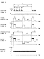
- FIG. 4 describes the processing performed by the synchronous detection device in accordance with the first preferred embodiment of the present invention.
- the period T (period of the synchronization signal SY) with which the pump light L2 is input to the other end of the optical fiber 14 is set to be two times the amount of time required for the pump light L2 to make a round trip between one end and the other end of the optical fiber 14. If this setting is made, both the amount of time required for the pump light L2 input from the other end of the optical fiber 14 to reach the one end of the optical fiber 14 and the amount of time required for the stimulated Brillouin scattered light occurring at one end of the optical fiber to reach the other end thereof are T/4.
- the detection light L11 including the probe light L1 via the optical fiber 14 and the stimulated Brillouin scattered light occurring in the optical fiber 14 is input to the light detector 17.
- the detection signal D1 that has been influenced by the stimulated Brillouin scattered light is output from the light detector 17.
- parts that have been influenced by stimulated Brillouin scattered light are represented by black stripes, and the parts marked by the reference symbols P1 to P4 each indicate parts that have been influenced by the stimulated Brillouin scattered light occurring at the positions P1 to P4 of the correlation peaks in FIG. 3 .
- the detection light L11 including the probe light L1 via the optical fiber 14 but not including the stimulated Brillouin scattered light is input to the light detector 17.
- the detection signal D1 that has not been influenced by stimulated Brillouin scattered light is not marked by black stripes
- the detection signal D1 influenced by the stimulated Brillouin scattered light and the detection signal D2 not influenced by the stimulated Brillouin scattered light are alternately output each T/2.
- the operating period of the timing adjuster 18a is set to T/2, so that, in each period thereof, a detection signal obtained by detecting light including the stimulated Brillouin scattered light occurring at the measurement point set within the optical fiber 14 and in the vicinity thereof is passed.
- the measurement point is set at the position of the correlation peak P1 shown in FIG. 3
- the timing adjuster 18a switches the on and off states so that, of the detection signals D1 output from the light detector 17, the part that has been influenced by the stimulated Brillouin scattered light occurring at the position of the correlation peak P1 and the vicinity thereof is passed.
- This inputs the detection signal D2 shown in FIG. 4 which is separated out by the timing adjuster 18a, to the lock-in amplifier 18b.
- the detection signal D2 When this detection signal D2 is input to the lock-in amplifier 18b, the detection signal D2, the polarity of which is not inverted, is output as a non-inverted signal from the non-inverter 21a, and the detection signal D2, the polarity of which is inverted, is output as an inverted signal from the inverter 21b.
- the synchronization signal SY having a period ofT is input to the synchronization signal input terminal Q2 of the lock-in amplifier 18b, and the connection between the input terminals a1 and a2 and the output terminal b1 of the switching unit 22 is switched each T/2.
- the output signal S1 of the switching unit 22 is the detection signal D2 in which the part not influenced by the stimulated Brillouin scattered light has its polarity inverted.
- the signal d11 corresponding to the detection signal obtained by detecting only the probe light L1 in the former half part T1 and the signal d12 corresponding to the detection signal obtained by detecting only the probe light L1 in the latter half part T2 cancel each other out.
- the measured value V1 of the DC voltmeter 25, as shown in FIG. 4 indicates the level of the stimulated Brillouin scattered light.
- the characteristics of the optical fiber 14 in the length direction can be measured by repeating the above-described operation while changing the position of the measurement point set in the optical fiber 14 by changing the separation timing of the timing adjuster 18a.
- the light detector 17 detects the probe light L1 via the optical fiber 14 and the detection light L11 including stimulated Brillouin scattered light occurring in the optical fiber 14, and, of the detection signal D1 output from the light detector 17, the timing adjuster 18a separates out the detection signal obtained by detecting the light in the vicinity of the measurement point set in the optical fiber 14, the separated out detection signal D2 being synchronously detected by the lock-in amplifier 18b.
- the timing adjuster 18a separates out the detection signal obtained by detecting the light in the vicinity of the measurement point set in the optical fiber 14, the separated out detection signal D2 being synchronously detected by the lock-in amplifier 18b.
- FIG. 5 is a block diagram illustrating the constitution of the main part of an optical fiber characteristics measurement device in accordance with a second preferred embodiment of the present invention.
- the optical fiber characteristics measurement device 2 of the second preferred embodiment differs from the optical fiber characteristics measurement device 1 of the first preferred embodiment by having a lock-in amplifier 30 (synchronous detection device) in place of the synchronous detection device 18.
- the optical fiber characteristics measurement device 1 of the first preferred embodiment is constituted with the timing adjuster 18a and the lock-in amplifier 18b provided as separate elements
- the optical fiber characteristics measurement device 2 of the second preferred embodiment is constituted to have a lock-in amplifier 30 having the timing adjuster 18a and the lock-in amplifier 18b provided integrally.
- the signal d11 corresponding to the detection signal obtained by detecting only the probe light L1 in the former half part T1 and the signal d12 corresponding to the detection signal obtained by detecting only the probe light L1 in the latter hall part T2 cancel each other out, and the measured value V1 of the DC voltmeter 25 indicates the level of the stimulated Brillouin scattered light.
- optical fiber characteristics measurement device and optical fiber characteristics measurement method of the present invention it is not necessary to use a relatively expensive optical switch as a timing adjuster as is conventionally done, and, using a low-cost electrical switch, it is possible to measure strain (temperature) as with conventional art.
Landscapes
- Physics & Mathematics (AREA)
- General Physics & Mathematics (AREA)
- Optics & Photonics (AREA)
- Chemical & Material Sciences (AREA)
- Analytical Chemistry (AREA)
- Optical Transform (AREA)
- Testing Of Optical Devices Or Fibers (AREA)
- Photometry And Measurement Of Optical Pulse Characteristics (AREA)
Abstract
Description
- The present invention relates to an optical fiber characteristics measurement device and method.
Priority is claimed on Japanese Patent Application No.2011-018951, filed on January 31, 2011 - All patents, patent applications, patent publications, scientific articles, and the like, which will hereinafter be cited or identified in the present application, will hereby be incorporated by reference in their entirety in order to describe more fully the state of the art to which the present invention pertains.
An optical fiber characteristics measurement device, as is widely known, is a device that inputs continuous light or pulse light into an optical fiber, receives scattered light or reflected light that occurs within the optical fiber, and measures temperature distribution, strain distribution, and other characteristics in the longitudinal direction of the optical fiber. In this optical fiber characteristics measurement device, because the received scattered light or reflected light varies in response to physical quantities (for example, temperature and strain) that influence the optical fiber, the optical fiber itself is used as a sensor. -
Patent Document 1 noted below discloses an optical fiber characteristics measurement device in which frequency-modulated continuous light (pump light and probe light) is sent into each respective end of the optical fiber, thereby forming periodic correlation peaks between the pump light and the probe light along the optical fiber, a characteristic of the optical fiber being measured by utilizing the property that the probe light is amplified by the stimulated Brillouin scattering only a positions of the correlation peaks. This optical fiber characteristics measurement device, by receiving amplified probe light at each position while varying the correlation peak positions within the optical fiber, can measure the characteristics of an optical fiber in the longitudinal direction. -
Patent Document 2 discloses an optical fiber characteristics measurement device in which frequency-modulated continuous light (probe light) and pulse light (pump light) are sent into one and into the other end of an optical fiber, causing successive correlation peaks in accordance with the position of the pump light that propagates within the optical fiber, so as to obtain only light (stimulated Brillouin scattered light) in the vicinity of a measurement point of the light exiting from the optical fiber, so as to measure the characteristics of the optical fiber at the measurement point. This optical fiber characteristics measurement device adjusts the modulation frequency of the probe light and the pump light and the timing of receiving the light exiting from the optical fiber, so as to move the measurement point, thereby enabling measurement of the characteristics at an arbitrary position along the longitudinal direction of the optical fiber. -
- [Patent Document 1] Japanese Patent (Granted) Publication No.
3667132 - [Patent Document 2] Japanese Patent (Granted) Publication No.
3607930 - The optical fiber characteristics measurement device disclosed in
Patent Document 2 has a timing adjuster in the front end of the optical detector that receives light exiting from the optical fiber and, by separating out light exiting from the optical fiber by the timing adjuster, receives at the optical detector only light from the vicinity of the measurement point. An optical switch that applies an LN (lithium niobate) modulator using an electro-optical effect, for example, implements such a timing adjuster (Pockels effect). - The above-noted optical switch can switch between the on state (state that passes light) and the off state (state that blocks light) at a high speed, and can, for example, also separate out light exiting from the optical fiber with a time interval of approximately several nanoseconds. Thus, if an optical switch such as this is used as a timing adjuster, an optical fiber characteristics measurement device having a high spatial resolution of approximately 1 cm can be achieved. However, the above-noted optical switch has a large insertion loss, has polarization dependency, and is expensive. For this reason, it can be envisioned that the following problems might occur in the future in improving the spatial resolution and reducing the cost of an optical fiber characteristics measurement device.
- Because the signal level (intensity of the received light signal) obtained by an optical fiber characteristics measurement device decreases as the spatial resolution increases, if the spatial resolution is made high, the S/N ratio (signal-to-noise ratio) inevitably decreases. Because the above-described optical switch has a high insertion loss of approximately 3 to 5 dB and further decreases the S/N ratio, an attempt to improve the spatial resolution of the optical fiber characteristics measurement device has the problem of causing a worsening of the measurement accuracy.
- The above-noted optical switch has polarization dependency, whereby the intensity of the passed light varies in accordance with the polarization direction of the incident light and, according to this characteristic, the insertion loss of the optical switch also varies in accordance with the polarization direction of the incident light. As a result, if an attempt is made to improve the spatial resolution of the optical fiber characteristics measurement device, there is the problem that the above-noted optical switch is a factor in worsening the measurement accuracy and a factor in worsening the stability and reproducibility of measurements.
- Although the above-noted optical switch often has a control device that performs feedback control of a bias voltage for the purpose of preventing temperature variations and time variations of the operating characteristics, this not only makes the constitution complex, but also, with a control signal for feedback control being superimposed on the light exiting from the optical fiber, has the problem of being a factor in lowering the S/N ratio. Also, because the above-noted optical switch is itself expensive, there is a problem of a disadvantage in terms of trying to reduce the cost of the optical fiber characteristics measurement device.
- The present invention was made in consideration of the above-noted situation, and has an object to provide an optical fiber characteristics measurement device and method that, without leading to a worsening of measurement accuracy, or a worsening of stability and reproducibility, can improve the spatial resolution and reduce the cost.
- To solve the above-described problems, an optical fiber characteristics measurement device (1,2) in accordance with the present invention may include: a light source (11) configured to emit a laser light modulated by a prescribed modulation frequency; a light inputting means (12, 13, 15, 16) configured to cause the laser light from the light source to enter one end and another end of an optical fiber (14) as continuous light (L1) and pulse light (L2), respectively; and a light detector (17) configured to detect light exiting from the optical fiber, and to measure a characteristic of the optical fiber by using a detection result of the light detector, characterized in that the optical fiber characteristics measurement device comprises: a synchronous detection device (18, 30) configured to separate out, of a detection signal (D1) output from the light detector, a detection signal obtained by detecting light in the vicinity of a measurement point set in the optical fiber, and to detect synchronously a detection signal separated out by using a synchronization signal (SY, SY1) having a prescribed period.
According to the present invention, the following steps are performed; separating out a detection signal obtaining by detecting light in the vicinity of the measurement point set in an optical fiber from a detection signal output from a light detector; and synchronously detecting the separated out detection signal using a synchronization signal having a prescribed period.
Also, in the optical fiber characteristics measurement device in accordance with the present invention, the synchronous detection device may include: a timing adjuster (18a) configured to separate out by passing, of the detection signal output from the light detector, a detection signal obtained by detecting light in the vicinity of a measurement point set in the optical fiber; and a synchronous detector (18b) configured to use the synchronization signal to synchronously detect the detection signal passed through the timing adjuster.
Also, in the optical fiber characteristics measurement device in accordance with the present invention, an operating period of the timing adjuster may be a period that is one-half a period of the synchronization signal.
Also, in the optical fiber characteristics measurement device in accordance with the present invention, the synchronous detection device may include: an inverter (21 b) configured to output an inverted signal that is the detection signal output from the light detector, with the polarity thereof inverted; a non-inverter (21a) configured to output a non-inverted signal that is the detection signal output from the light detector, with the polarity thereof not inverted; a switching unit (31) configured to separate out by alternately outputting the inverted signal output from the inverter and the non-inverted signal output from the non-inverter at a timing of the output from the light detector of a detection signal obtained by detecting light in the vicinity of the measurement point set in the optical fiber; and a lowpass filter (24) configured to filter a signal (S1) output from the switching unit.
Also, in the optical fiber characteristics measurement device in accordance with the present invention, a period of the pulse light input to the other end of the optical fiber may be set to at least two times an amount of time required for the pulse light to make a round trip from one end to the other end of the optical fiber, and a period of the synchronization signal may be the same as the period of the pulse light being input to the other end of the optical fiber.
A method of measuring a characteristics of an optical fiber in accordance with the present invention may include: inputting laser light modulated by a prescribed modulation frequency to one end and another end of the optical fiber (14) as continuous light (L1) and pulse light (L2), respectively; and detecting with a light detector (17) light exiting from the optical fiber, characterized in that the method comprises: separating out, of a detection signal output from the light detector, a detection signal obtained by detecting light in the vicinity of a measurement point set in the optical fiber; and synchronously detecting a detection signal separated out by using a synchronization signal having a prescribed period. - According to the present invention, by separating out a detection signal obtaining by detecting light in the vicinity of the measurement point set in an optical fiber from a detection signal output from a light detector, and synchronously detecting the separated out detection signal using a synchronization signal having a prescribed period, it is possible to achieve the effect of improving the spatial resolution and reducing cost, without leading to a worsening of measurement accuracy or a worsening of stability and reproducibility.
-
-
FIG. 1 is a block diagram illustrating the constitution of the main part of an optical fiber characteristics measurement device in accordance with a first preferred embodiment of the present invention. -
FIG. 2 is a block diagram illustrating the constitution of the main part of the lock-in amplifier of the optical fiber characteristics measurement device in accordance with the first preferred embodiment of the present invention. -
FIG. 3 is a diagram illustrating the condition in which correlation peaks occur within the optical fiber accompanying the advancing of the pump light. -
FIG. 4 is a diagram for describing the processing performed by the synchronous detection device in accordance with the first preferred embodiment of the present invention. -
FIG. 5 is a block diagram illustrating the constitution of the main part of an optical fiber characteristics measurement device in accordance with a second preferred embodiment of the present invention. -
FIG. 6 is a block diagram illustrating the constitution of the main part of the lock-in amplifier of the optical fiber characteristics measurement device in accordance with the second preferred embodiment of the present invention. -
FIG. 7 is a diagram for describing the processing performed by the synchronous detection device as a lock-in amplifier in accordance with the second preferred embodiment of the present invention. - An optical fiber characteristics measurement device and method in accordance with preferred embodiments of the present invention will be described in detail below, with references made to the drawings. The descriptions of preferred embodiments of the present invention to follow are merely specific descriptions of the invention set forth in the attached claims and equivalents thereto, and it will be clear to a person skilled in the art, based on the present disclosure, that these are not intended to impose restrictions.
-
FIG. 1 is a block diagram illustrating the constitution of the main part of an optical fiber characteristics measurement device in accordance with a first preferred embodiment of the present invention. As shown inFIG. 1 , the optical fibercharacteristics measurement device 1 of the first preferred embodiment has alight source 11, an optical splitter 12 (light inputting means), an optical modulator 13 (light inputting means), anoptical fiber 14, a pulse modulator 15 (light inputting means), a directional coupler 16 (light inputting means), alight detector 17, and asynchronous detection device 18, and measures the characteristics (for example temperature distribution or strain distribution) of theoptical fiber 14 in the longitudinal direction. - The
light source 11 has asemiconductor laser 11a and asignal generator 11b, and emits laser light modulated by a prescribed modulation frequency fm. In this case, thesemiconductor laser 11a that is used can be, for example, an MQW DFB (multi-quantum well, distributed feedback) laser diode that is compact and emits laser light having a narrow spectral width. Thesignal generator 11b outputs to thesemiconductor laser 11a a sinewave signal (modulation signal) that frequency modulates the laser light exiting from thesemiconductor laser 11a by the modulation frequency fm. Theoptical splitter 12 splits the laser light exiting from thelight source 11 into two, for example, with a 1:1 intensity ratio. - The
optical modulator 13 has amicrowave generator 13a and an SSB (single sideband)optical modulator 13b, and modulates (shifts the light frequency of) one of the laser lights split by theoptical splitter 12 to generate a sideband (single sideband) with respect to the center frequency of the laser light. In the first preferred embodiment, the single sideband on the low-frequency side is taken as the output from theoptical modulator 13. Themicrowave generator 13a outputs a microwave signal having the frequency of the frequency shift imparted to one of the laser lights split by theoptical splitter 12. The SSBoptical modulator 13b generates a single sideband signal having a frequency difference with respect to the center frequency of the input light that is equal to the frequency of the microwave signal output from themicrowave generator 13a. The frequency of the microwave signal output from themicrowave generator 13a is variable. The light modulated by theoptical modulator 13 is input as the probe light L1 (continuous light) into theoptical fiber 14 from one end thereof. - The
pulse modulator 15 has asignal generator 15a and alight intensity modulator 15b, and generates a pulse light by making the other laser light split by theoptical splitter 12 into a pulse. Thesignal generator 15a outputs a timing signal that establishes the timing of making the laser light into a pulse light. Thelight intensity modulator 15b is, for example, an EO (electro-optical) switch, which forms the laser light from theoptical splitter 12 into a pulse light at a timing that is established by the timing signal output from thesignal generator 15a. - In this case, the
pulse modulator 15 generates a pulse light with the period T given by the following Equation (1) and having a pulse width tpw given by the following Equation (2). In Equation (1) and Equation (2) below, L is the length of the optical fiber 14 (from one end to the other end), n is the refractive index of theoptical fiber 14, c is the speed of light, dm is the interval of the correlation peaks formed in theoptical fiber 14, and fm is the modulation frequency of the laser light exiting from thelight source 11.

That is, from the above Equation (1), the period T with which thepulse modulator 15 generates the pulse light is set to at least two times the amount of time required for the pulse light to make a round trip between one end and the other end of theoptical fiber 14. - The
directional coupler 16 inputs laser light that has been made pulse light and output from thepulse modulator 15 as a pump light L2 into theoptical fiber 14 from the other end thereof, and causes light (detection light L11) that includes a probe light L1 that has propagated through and exited from the other end of theoptical fiber 14 to be incident toward thelight detector 17. The stimulated Brillouin scattering phenomenon occurring within theoptical fiber 14 influences the intensity of the detection light L11. - The
light detector 17 has, for example, a high-sensitivity light-receiving element such as an avalanche photodiode, detects (receives) the above-noted detection light L11 (light exiting from the other end of theoptical fiber 14 via the directional coupler 16), and outputs a detection signal D1. InFIG. 1 , although omitted from the illustration, thelight detector 17 has, in addition to the above-noted light-receiving element, a light wavelength filter, and selects and detects, of the probe light L1 from the detection light L11, the power of only light of the sideband on the low-frequency side. In the first preferred embodiment, because the SSBoptical modulator 13b is used, the above-noted light wavelength filter may be omitted. By providing the light wavelength filter, however, although there is an increase in cost, because unwanted frequency components can be suppressed, the measurement accuracy can be improved. - The
synchronous detection device 18 has atiming adjuster 18a and a lock-inamplifier 18b (synchronous detector) and synchronously detects the detection signal D1 output from thelight detector 17. Specifically, thesynchronous detection device 18, of the detection signal D1 output from thelight detector 17, detects and separates out light that includes stimulated Brillouin scattered light occurring at the measurement point set within theoptical fiber 14 and in the vicinity thereof, and uses a synchronization signal SY (refer toFIG. 2 andFIG. 4 ) having a prescribed period to synchronously detect the separated out detection signal D2. - The
timing adjuster 18a is implemented by, for example, an electrical switch (high-speed analog switch) that can switch at high speed between the on state (state in which the detection signal D1 is passed) and the off state (state in which the detection signal D1 is blocked). Of the detection signal D1 output from thelight detector 17, thetiming adjuster 18a separates out the detection signal detected by passing a detection signal obtained by detecting light that includes stimulated Brillouin scattered light occurring at the measurement point set within theoptical fiber 14 and in the vicinity thereof. The operating period of thetiming adjuster 18a is set to a period that is one-half of the period of the above-noted synchronization signal SY. - In this case, it is desirable that the
timing adjuster 18a be capable of separating out the detection signal D1 with a time interval of approximately several nanoseconds and have low loss (for example, 1 dB or lower). If separation out with a time interval of approximately several nanoseconds is possible, a spatial resolution of 1 cm or better can be achieved, and if the loss is low, because there is no great reduction in the S/N ratio, measurement accuracy can be improved. By using an electrical switch as thetiming adjuster 18a, compactness and low cost can be achieved. Additionally, because there is no polarization dependency as there is with an optical switch, there is no worsening of stability or reproducibility, and also it is possible to perform measurement over a wide temperature range from -40 to +80°C. - The lock-in
amplifier 18b uses the above-described synchronization signal SY to synchronously detect the detection signal D2 that has passed through thetiming adjuster 18a (the detection signal separated out by thetiming adjuster 18a). In this case, the period of the synchronization signal SY is set to a period that is the same as the period of the pump light L2 incident to the other end of the optical fiber 14 (at least two times the amount of time required for the pulse light to make a round trip between one end and the other end of the optical fiber 14). -
FIG. 2 is a block diagram illustrating the constitution of the main part of the lock-in amplifier of the optical fiber characteristics measurement device in accordance with the first preferred embodiment of the present invention. As shown inFIG. 2 , the lock-inamplifier 18b has a non-inverter 21a, aninverter 21b, a switchingunit 22, aphase shifter 23, alowpass filter 24, and aDC voltmeter 25, and uses the synchronization signal SY input to the synchronization signal input terminal Q2 to synchronously detect the detection signal D2 input to the signal input terminal Q1. - The non-inverter 21a outputs the detection signal D2 input to the signal input terminal Q1 as is, without inverting the polarity thereof, and the
inverter 21 b inverts and outputs the detection signal D2 input to the signal input terminal Q1. That is, the non-inverter 21a outputs a non-inverted signal that does not invert the polarity of the detection signal D2, and theinverter 21b outputs an inverted signal that inverts the polarity of the detection signal D2. The switchingunit 22 has an input terminal a1, to which the output terminal of the non-inverter 21a is connected, an input terminal a2, to which the output terminal of theinverter 21b is connected, and an output terminal b1, to which thelowpass filter 24 is connected, and, based on the synchronization signal SY via thephase shifter 23, switches the output terminal b1 between the input terminals a1 and a2. - The
phase shifter 23 adjusts the phase by changing the phase of the synchronization signal SY input to the synchronization signal input terminal Q2. Thelowpass filter 24 filters the output signal S1 output from the output terminal b1 of the switchingunit 22. Specifically, it passes low-frequency components of the output signal S1 (frequency components lower than the cutoff frequency) and blocks high-frequency components that are above the cutoff frequency. TheDC voltmeter 25 measures the voltage (DC voltage) value of the signal output from thelowpass filter 24. - In the above-noted constitution, the
optical splitter 12 splits laser light that is frequency modulated with the modulation frequency of fm when it is incident from thelight source 11. One part of the laser light split by theoptical splitter 12 is input to theoptical modulator 13 and is modulated by the SSBoptical modulator 13b, thereby generating a single sideband with respect to the center frequency of the laser light. The laser light (continuous light) having a signal sideband that has exited from theoptical modulator 13 enters one end of theoptical fiber 14 as the probe light L1. - In contrast, the other laser light split by the
optical splitter 12 enters thepulse modulator 15 and becomes pulse light by intensity modulation by thelight intensity modulator 15b. Specifically, a pulse light having a pulse width given by the above-described Equation (2) is generated with a period T given by the above-described Equation (1). This pulse light, via thedirectional coupler 16, enters the other end of theoptical fiber 14 as the pump light L2. - When the probe light L1 as continuous light frequency modulated by the modulation frequency fm and the pump light L2 as pulse light enter the
optical fiber 14, as shown inFIG. 3 , as the pump light L2 propagates within theoptical fiber 14, correlation peaks P0 to P4 occur at different positions in theoptical fiber 14.FIG. 3 shows the condition in which correlation peaks occur within theoptical fiber 14 accompanying the advancing of the pump light. InFIG. 3 , to avoid having the drawing become complex, only the five correlation peaks P0 to P4 are shown. In the example shown inFIG. 3 , the condition in which the pump light L2 is passing the vicinity of the correlation peak P2 is shown. InFIG. 3 , the correlation peaks P0 and P1 shown by broken lines are correlation peaks that have already been passed, and the correlation peaks P3 and P4 are correlation peaks that are going to be passed as the pump light L2 advances. - The interval dm of the correlation peaks is given by the following Equation (3).

That is, the interval dm of the correlation peaks can be changed by changing the modulation frequency fm in thelight source 11, thereby moving the positions at which the correlation peaks P1 to Pn occur. However, the position at which the zero-order correlation peak P0 occurs, at which the difference between the light paths of the probe light L1 and the pump light L2 is zero cannot be changed by changing the modulation frequency fm. For this reason, as shown inFIG. 3 , the position of occurrence of the zero-order correlation peak P0 is set to fall outside theoptical fiber 14. - At the positions P1 to P4 of each of the correlation peaks, the probe light L1 obtains a gain by stimulated Brillouin amplification by the pump light L2. At the position of the correlation peaks, if the frequency difference between the pump light L2 and the probe light L1 is changed, with the pump light L2 as the reference, a spectrum known as the Brillouin gain spectrum (BGS) having a Lorentzian function profile is obtained, with the center frequency as the Brillouin frequency shift vB. The Brillouin frequency shift vB. varies and is dependent upon the material, temperature, and strain of the
optical fiber 14, and it is known in particular to exhibit a linear change with respect to the strain. For this reason, by detecting the peak frequency of the Brillouin gain spectrum, it is possible to determine the amount of strain of theoptical fiber 14. - The probe light L1 via the
optical fiber 14 and the stimulated Brillouin scattered light that has occurred in theoptical fiber 14 enter thelight detector 17 as the detected light L11 via thedirectional coupler 16, after exiting from the other end of theoptical fiber 14. Then, the non-illustrated light wavelength filter of thelight detector 17 selects the light of the sideband on the low-frequency side, the intensity of which is detected, the detection signal D1 indicating the detection result being output from thelight detector 17. The detection signal D1 output from thelight detector 17 is input to thesynchronous detection device 18 and is synchronously detected. -
FIG. 4 describes the processing performed by the synchronous detection device in accordance with the first preferred embodiment of the present invention. To simplify the description that follows, the period T (period of the synchronization signal SY) with which the pump light L2 is input to the other end of theoptical fiber 14 is set to be two times the amount of time required for the pump light L2 to make a round trip between one end and the other end of theoptical fiber 14. If this setting is made, both the amount of time required for the pump light L2 input from the other end of theoptical fiber 14 to reach the one end of theoptical fiber 14 and the amount of time required for the stimulated Brillouin scattered light occurring at one end of the optical fiber to reach the other end thereof are T/4. - In the former half part T1 of one period T of the synchronization signal SY, the detection light L11 including the probe light L1 via the
optical fiber 14 and the stimulated Brillouin scattered light occurring in theoptical fiber 14 is input to thelight detector 17. As a result, as shown inFIG. 4 , the detection signal D1 that has been influenced by the stimulated Brillouin scattered light is output from thelight detector 17. InFIG. 4 , parts that have been influenced by stimulated Brillouin scattered light are represented by black stripes, and the parts marked by the reference symbols P1 to P4 each indicate parts that have been influenced by the stimulated Brillouin scattered light occurring at the positions P1 to P4 of the correlation peaks inFIG. 3 . - In contrast, in the latter half part T2 of one period T of the synchronization signal SY, the detection light L11 including the probe light L1 via the
optical fiber 14 but not including the stimulated Brillouin scattered light is input to thelight detector 17. As a result, as shown inFIG. 4 , the detection signal D1 that has not been influenced by stimulated Brillouin scattered light (is not marked by black stripes) is output from thelight detector 17. Because the pump light L2 is input repeatedly with the period of T, the detection signal D1 influenced by the stimulated Brillouin scattered light and the detection signal D2 not influenced by the stimulated Brillouin scattered light are alternately output each T/2. - In this case, as shown in
FIG. 4 , the operating period of thetiming adjuster 18a is set to T/2, so that, in each period thereof, a detection signal obtained by detecting light including the stimulated Brillouin scattered light occurring at the measurement point set within theoptical fiber 14 and in the vicinity thereof is passed. In the example shown inFIG. 4 , the measurement point is set at the position of the correlation peak P1 shown inFIG. 3 , and thetiming adjuster 18a switches the on and off states so that, of the detection signals D1 output from thelight detector 17, the part that has been influenced by the stimulated Brillouin scattered light occurring at the position of the correlation peak P1 and the vicinity thereof is passed. This inputs the detection signal D2 shown inFIG. 4 , which is separated out by thetiming adjuster 18a, to the lock-inamplifier 18b. - When this detection signal D2 is input to the lock-in
amplifier 18b, the detection signal D2, the polarity of which is not inverted, is output as a non-inverted signal from the non-inverter 21a, and the detection signal D2, the polarity of which is inverted, is output as an inverted signal from theinverter 21b. In this case, the synchronization signal SY having a period ofT is input to the synchronization signal input terminal Q2 of the lock-inamplifier 18b, and the connection between the input terminals a1 and a2 and the output terminal b1 of the switchingunit 22 is switched each T/2. As a result, as shown inFIG. 4 , the output signal S1 of the switchingunit 22 is the detection signal D2 in which the part not influenced by the stimulated Brillouin scattered light has its polarity inverted. - When such an
output signal S 1 is input to thelowpass filter 24, the signal d11 corresponding to the detection signal obtained by detecting only the probe light L1 in the former half part T1 and the signal d12 corresponding to the detection signal obtained by detecting only the probe light L1 in the latter half part T2 cancel each other out. When these signals d11 and d12 cancel each other out over a plurality of periods, the measured value V1 of theDC voltmeter 25, as shown inFIG. 4 , indicates the level of the stimulated Brillouin scattered light. The characteristics of theoptical fiber 14 in the length direction can be measured by repeating the above-described operation while changing the position of the measurement point set in theoptical fiber 14 by changing the separation timing of thetiming adjuster 18a. - As described above, in the first preferred embodiment, the
light detector 17 detects the probe light L1 via theoptical fiber 14 and the detection light L11 including stimulated Brillouin scattered light occurring in theoptical fiber 14, and, of the detection signal D1 output from thelight detector 17, thetiming adjuster 18a separates out the detection signal obtained by detecting the light in the vicinity of the measurement point set in theoptical fiber 14, the separated out detection signal D2 being synchronously detected by the lock-inamplifier 18b. As a result, there is no worsening of measurement accuracy or stability as in the case of using a conventional optical switch, and it is possible to improve the spatial resolution and reduce the cost. - Specifically, whereas the insertion loss when using a conventional optical switch is approximately 3 to 5 dB, if this can be reduced to approximately 1 dB, even if the spatial resolution is improved it is possible to measure the characteristics of the
optical fiber 14 with high accuracy. For example, if the insertion loss is reduced from 3 dB to 1 dB, even if the spatial resolution is improved by approximately 1.5 times, good measurement accuracy is possible, and if the insertion loss is reduced from 5 dB to 1 dB, even if the spatial resolution is improved by approximately 2 times, good measurement accuracy is possible. -
FIG. 5 is a block diagram illustrating the constitution of the main part of an optical fiber characteristics measurement device in accordance with a second preferred embodiment of the present invention. As shown inFIG. 5 , the optical fibercharacteristics measurement device 2 of the second preferred embodiment differs from the optical fibercharacteristics measurement device 1 of the first preferred embodiment by having a lock-in amplifier 30 (synchronous detection device) in place of thesynchronous detection device 18. Whereas the optical fibercharacteristics measurement device 1 of the first preferred embodiment is constituted with thetiming adjuster 18a and the lock-inamplifier 18b provided as separate elements, the optical fibercharacteristics measurement device 2 of the second preferred embodiment is constituted to have a lock-inamplifier 30 having thetiming adjuster 18a and the lock-inamplifier 18b provided integrally. -
FIG. 6 is a block diagram illustrating the constitution of the main part of the lock-in amplifier of the optical fiber characteristics measurement device in accordance with the second preferred embodiment of the present invention. As shown inFIG. 6 , the lock-inamplifier 30 has a constitution in which aswitching unit 31 replaces the switchingunit 22 of the lock-inamplifier 18b shown inFIG. 2 . In the lock-inamplifier 30, a synchronization signal SY1 is used in place of the synchronization signal SY shown inFIG. 2 andFIG. 4 . Details of the synchronization signal SY1 will be described later. - The switching
unit 31, in addition to an input terminal a1 to which the output terminal of the non-inverter 21 a is connected, an input terminal a2 to which the output terminal of theinverter 21b is connected, and an output terminal b1 to which thelowpass filter 24 is connected, has an input terminal a3 that is electrically insulated from the input terminals a1 and a2 and, based on the synchronization signal SY1 via thephase shifter 23, switches the connection between the input terminals a1, a2, and a3 and the output terminal b1. If the input terminal a3 is electrically insulated from the input terminals a1 and a2, it may be open or shorted to ground or the like, or may be terminated. An electrical switch (high-speed analog switch), for example, similar to that used in thetiming adjuster 18a shown inFIG. 1 , may be used as the switchingunit 31. -
FIG. 7 describes the processing performed by the synchronous detection device as a lock-in amplifier in accordance with the second preferred embodiment of the present invention. In the second preferred embodiment as well, to simplify the description, the period T with which the pump light L2 is input to the other end of theoptical fiber 14 is set to be two times the amount of time required for the pump light L2 to make a round trip between one end and the other end of theoptical fiber 14. The period of the synchronization signal SY1 is the same as the period of the synchronization signal SY, in this case being the period T. - In the second preferred embodiment as well, similar to the first preferred embodiment, in the former half part T1 of one period T of the synchronization signal SY1, the detection light L11 including the probe light L1 via the
optical fiber 14 and the stimulated Brillouin scattered light occurring in theoptical fiber 14 is input to thelight detector 17. In the latter half part T2 of one period T of the synchronization signal SY1, the detection light L11 including the probe light L1 via theoptical fiber 14 but not including the stimulated Brillouin scattered light is input to thelight detector 17. As a result, the detection signal D1 output from thelight detector 17 is one that has been influenced by the stimulated Brillouin scattered light in the former half part T1, but is one that has not been influenced by the stimulated Brillouin scattered light in the latter half part T2, this detection signal D1 being input to the lock-inamplifier 30. - When the detection signal D1 is input to the lock-in
amplifier 30, the detection signal D1, the polarity of which is not inverted, is output as a non-inverted signal from the non-inverter 21 a, and the detection signal D1, the polarity of which is inverted, is output as an inverted signal from theinverter 21b. The non-inverted signal output from the non-inverter 21 a is input to the input terminal a1 of the switchingunit 31, and the inverted signal output form theinverter 21b is input to the input terminal a2 of the switchingunit 31. - In this case, as shown in
FIG. 7 , the synchronization signal SY1 used in the lock-inamplifier 30 is a signal having a period ofT, which is the same as the period of synchronization signal SY shown inFIG. 4 . However, the synchronization signal SY1 is a signal that, during almost all of one period T, causes the connection between the input terminal a3 and the output terminal b1 of the switchingunit 31, and causes connection between the input terminal a1 and the output terminal b1 of the switchingunit 31 at only a specific timing in the former half part T1, and a connection between the input terminal a2 and the output terminal b1 of the switchingunit 31 at only a specific timing in the latter half part T2. - Specifically, the synchronization signal SY1, in the former half part T1 of one period T, causes a connection between the input terminal a1 and the output terminal b1 of the switching
unit 31 at a timing at which the detection signal D1 obtained by detecting light including the stimulated Brillouin scattered light occurring at the measurement point set in theoptical fiber 14 and in the vicinity thereof is output from the light detector 17 (precisely, the timing at which the non-inverted signal of the detection signal D1 is output from the non-inverter 21 a). In the latter half part T2 of one period T, a connection is caused between the input terminal a2 and the output terminal b1 of the switchingunit 31 at only a timing similar to the timing in the former half part T1. - When the switching
unit 31 performs switching by the above-described synchronization signal SY1, the switchingunit 31 separates out the non-inverted signal input to the input terminal a1 and the inverted signal input to the input terminal a2. As a result, the switchingunit 31 outputs an output signal S I, as shown inFIG. 7 , similar to the output signal S1 shown inFIG. 4 . When this output signal S1 is input to thelowpass filter 24, similar to the first preferred embodiment, the signal d11 corresponding to the detection signal obtained by detecting only the probe light L1 in the former half part T1 and the signal d12 corresponding to the detection signal obtained by detecting only the probe light L1 in the latter hall part T2 cancel each other out, and the measured value V1 of theDC voltmeter 25 indicates the level of the stimulated Brillouin scattered light. - In this case, the timing of switching by the switching
unit 31 changes depending upon the synchronization signal SY1. As a result, in the second preferred embodiment, the characteristics of theoptical fiber 14 can be measured in the length direction, in the same manner as in the first preferred embodiment, by repeating the above-described operation while changing the position of the measurement point set in theoptical fiber 14 by changing the switching timing of the switchingunit 31 using the synchronization signal SY1. - As described above, in the second preferred embodiment, the lock-in
amplifier 30 implements the separation out performed by thetiming adjuster 18a and the synchronous detection performed by the lock-inamplifier 18b of the first preferred embodiment. As a result, similar to the first preferred embodiment, the spatial resolution can be improved, and the cost can be reduced, without a worsening of the measurement accuracy or a worsening of stability or reproducibility. Also, in the second preferred embodiment, the integration of the function of thetiming adjuster 18a and the function of the lock-inamplifier 18b into the lock-inamplifier 30 is advantageous in achieving compactness and cost reduction. - Although the foregoing has been a description of an optical fiber characteristics measurement device and method in accordance with preferred embodiments of the present invention, the present invention is not restricted to the above-described preferred embodiments, and can be freely changed within the scope thereof. For example, it is desirable to adopt a constitution providing an optical delay unit and an optical isolator between the
optical modulator 13 and the one end of theoptical fiber 14. Providing an optical delay unit enables adjustment of the positions of the correlation peaks formed in theoptical fiber 14 and, as described usingFIG. 3 , facilitates the setting of the position of occurrence of the zero-order correlation peak P0 outside theoptical fiber 14. Providing an optical isolator, because light directed from theoptical fiber 14 toward the optical modulator 13 (for example, the pump light L2) can be blocked, enables a reduction in noise and the like.
That is, the present invention is not restricted to the above-described preferred embodiments, but rather is restricted by the scope of the attached claims. - According to the optical fiber characteristics measurement device and optical fiber characteristics measurement method of the present invention, it is not necessary to use a relatively expensive optical switch as a timing adjuster as is conventionally done, and, using a low-cost electrical switch, it is possible to measure strain (temperature) as with conventional art.
-
- 1
- Optical fiber characteristics measurement device
- 2
- Optical fiber characteristics measurement device
- 11
- Light source
- 12
- Optical splitter
- 13
- Optical modulator
- 14
- Optical fiber
- 15
- Pulse modulator
- 16
- Directional coupler
- 17
- Light detector
- 18
- Synchronous detection device
- 18a
- Timing adjuster
- 18b
- Lock-in amplifier
- 21a
- Non-inverter
- 21b
- Inverter
- 24
- Lowpass filter
- 30
- Lock-in amplifier
- 31
- Switching unit
- D1
- Detection signal
- L1
- Probe light
- L2
- Pump light
- S1
- Output signal
- SY
- Synchronization signal
- SY1
- Synchronization signal
Claims (6)
- An optical fiber characteristics measurement device comprising:a light source configured to emit a laser light modulated by a prescribed modulation frequency;a light inputting means configured to cause the laser light from the light source to enter one end and another end of an optical fiber as continuous light and pulse light, respectively; anda light detector configured to detect light exiting from the optical fiber, and to measure a characteristic of the optical fiber by using a detection result of the light detector,characterized in that the optical fiber characteristics measurement device comprises:a synchronous detection device configured to separate out, of a detection signal output from the light detector, a detection signal obtained by detecting light in the vicinity of a measurement point set in the optical fiber, and to detect synchronously a detection signal separated out by using a synchronization signal having a prescribed period.
- The optical fiber characteristics measurement device according to claim 1, wherein the synchronous detection device comprises:a timing adjuster configured to separate out by passing, of the detection signal output from the light detector, a detection signal obtained by detecting light in the vicinity of a measurement point set in the optical fiber; anda synchronous detector configured to use the synchronization signal to synchronously detect the detection signal passed through the timing adjuster.
- The optical fiber characteristics measurement device according to claim 2, wherein an operating period of the timing adjuster is a period that is one-half a period of the synchronization signal.
- The optical fiber characteristics measurement device according to claim 1, wherein the synchronous detection device comprises:an inverter configured to output an inverted signal that is the detection signal output from the light detector, with the polarity thereof inverted;a non-inverter configured to output a non-inverted signal that is the detection signal output from the light detector, with the polarity thereof not inverted;a switching unit configured to separate out by alternately outputting the inverted signal output from the inverter and the non-inverted signal output from the non-inverter at a timing of the output from the light detector of a detection signal obtained by detecting light in the vicinity of the measurement point set in the optical fiber; anda lowpass filter configured to filter a signal output from the switching unit.
- The optical fiber characteristics measurement device according to any one of claim 1 to claim 4, wherein
a period of the pulse light input to the other end of the optical fiber is set to at least two times an amount of time required for the pulse light to make a round trip from one end to the other end of the optical fiber, and
a period of the synchronization signal is the same as the period of the pulse light being input to the other end of the optical fiber. - A method of measuring a characteristics of an optical fiber, comprising:inputting laser light modulated by a prescribed modulation frequency to one end and another end of the optical fiber as continuous light and pulse light, respectively; anddetecting with a light detector light exiting from the optical fiber,characterized in that the method comprises:separating out, of a detection signal output from the light detector, a detection signal obtained by detecting light in the vicinity of a measurement point set in the optical fiber; andsynchronously detecting a detection signal separated out by using a synchronization signal having a prescribed period.
Applications Claiming Priority (2)
| Application Number | Priority Date | Filing Date | Title |
|---|---|---|---|
| JP2011018951A JP5654891B2 (en) | 2011-01-31 | 2011-01-31 | Optical fiber characteristic measuring apparatus and method |
| PCT/JP2012/051754 WO2012105429A1 (en) | 2011-01-31 | 2012-01-27 | Optical fiber characteristics measurement device and method |
Publications (3)
| Publication Number | Publication Date |
|---|---|
| EP2672235A1 true EP2672235A1 (en) | 2013-12-11 |
| EP2672235A4 EP2672235A4 (en) | 2015-04-22 |
| EP2672235B1 EP2672235B1 (en) | 2016-09-28 |
Family
ID=46602645
Family Applications (1)
| Application Number | Title | Priority Date | Filing Date |
|---|---|---|---|
| EP12742488.5A Active EP2672235B1 (en) | 2011-01-31 | 2012-01-27 | Optical fiber characteristics measurement device and method |
Country Status (6)
| Country | Link |
|---|---|
| US (1) | US9109977B2 (en) |
| EP (1) | EP2672235B1 (en) |
| JP (1) | JP5654891B2 (en) |
| CN (1) | CN103328933B (en) |
| CA (1) | CA2826007C (en) |
| WO (1) | WO2012105429A1 (en) |
Cited By (1)
| Publication number | Priority date | Publication date | Assignee | Title |
|---|---|---|---|---|
| CN110631617A (en) * | 2019-09-23 | 2019-12-31 | 苏州光格设备有限公司 | Long-distance high-resolution Brillouin optical time domain analysis method |
Families Citing this family (15)
| Publication number | Priority date | Publication date | Assignee | Title |
|---|---|---|---|---|
| JPWO2014091754A1 (en) * | 2012-12-12 | 2017-01-05 | 日本電気株式会社 | Optical fiber sensor and sensing method thereof |
| CN104142224B (en) * | 2014-07-22 | 2015-05-20 | 河海大学 | Multi-target multi-degree-of-freedom static and dynamic testing device and method for distributed sensing optical fiber |
| FR3032323B1 (en) * | 2015-02-03 | 2017-03-17 | Commissariat Energie Atomique | METHOD AND DEVICE FOR PHASE MODULATION OF A CARRIER WAVE AND APPLICATION TO THE DETECTION OF PHASE CODED MULTI-LEVEL DIGITAL SIGNALS |
| JP6713679B2 (en) * | 2015-02-10 | 2020-06-24 | 国立大学法人 東京大学 | Optical fiber characteristic measuring device and optical fiber characteristic measuring method |
| JP6288013B2 (en) * | 2015-09-07 | 2018-03-07 | 横河電機株式会社 | Optical fiber characteristic measuring device |
| JPWO2017221890A1 (en) * | 2016-06-20 | 2019-05-16 | 住友電気工業株式会社 | Optical fiber wiring method, optical fiber wiring device and optical fiber transmission characteristic measurement system |
| CN107515100B (en) * | 2017-08-15 | 2019-08-20 | 昆山金鸣光电科技有限公司 | A kind of pulsed light fiber switch condition detecting system |
| JP6791113B2 (en) * | 2017-12-27 | 2020-11-25 | 横河電機株式会社 | Optical fiber characteristic measuring device and optical fiber characteristic measuring method |
| JP6773091B2 (en) * | 2018-09-07 | 2020-10-21 | 横河電機株式会社 | Optical fiber characteristic measuring device and optical fiber characteristic measuring method |
| JP6791218B2 (en) * | 2018-09-07 | 2020-11-25 | 横河電機株式会社 | Optical fiber characteristic measuring device and optical fiber characteristic measuring method |
| CN111609875B (en) * | 2020-06-10 | 2021-12-28 | 电子科技大学 | Digital domain adjustable distributed optical fiber sensing system and method based on chirp continuous light |
| JP7613421B2 (en) | 2022-06-29 | 2025-01-15 | 横河電機株式会社 | Signal detection device and optical fiber characteristic measuring device |
| WO2024047744A1 (en) * | 2022-08-30 | 2024-03-07 | 日本電気株式会社 | Relaxation control system, relaxation control device, and relaxation control method |
| JP7740194B2 (en) | 2022-10-13 | 2025-09-17 | 横河電機株式会社 | Optical fiber characteristic measuring device and optical fiber characteristic measuring method |
| JP2024150208A (en) | 2023-04-10 | 2024-10-23 | 横河電機株式会社 | Measurement device, measurement method, and measurement program |
Family Cites Families (8)
| Publication number | Priority date | Publication date | Assignee | Title |
|---|---|---|---|---|
| JPH1123419A (en) * | 1997-06-30 | 1999-01-29 | Ando Electric Co Ltd | Optical fiber characteristics measurement device |
| JP3667132B2 (en) | 1998-12-14 | 2005-07-06 | アンリツ株式会社 | Brillouin gain spectrum measurement method and apparatus |
| JP3607930B2 (en) * | 2001-07-02 | 2005-01-05 | 和夫 保立 | Optical fiber characteristic measuring apparatus and method |
| JP3905780B2 (en) * | 2002-03-01 | 2007-04-18 | 日本電信電話株式会社 | Brillouin spectral distribution measuring method and apparatus |
| JP2005147909A (en) * | 2003-11-18 | 2005-06-09 | Meisei Electric Co Ltd | Measuring instrument using optical fiber grating sensor |
| JP4100574B2 (en) * | 2005-12-01 | 2008-06-11 | 国立大学法人 東京大学 | Optical fiber characteristic measuring apparatus and optical fiber characteristic measuring method |
| EP2063245A4 (en) * | 2006-08-24 | 2012-03-14 | Sumitomo Electric Industries | SENSOR FOR DISTRIBUTING FIBER OPTIC CHARACTERISTICS |
| JP5043714B2 (en) * | 2008-02-21 | 2012-10-10 | 和夫 保立 | Optical fiber characteristic measuring apparatus and method |
-
2011
- 2011-01-31 JP JP2011018951A patent/JP5654891B2/en active Active
-
2012
- 2012-01-27 US US13/982,423 patent/US9109977B2/en active Active
- 2012-01-27 WO PCT/JP2012/051754 patent/WO2012105429A1/en not_active Ceased
- 2012-01-27 EP EP12742488.5A patent/EP2672235B1/en active Active
- 2012-01-27 CA CA2826007A patent/CA2826007C/en active Active
- 2012-01-27 CN CN201280005593.XA patent/CN103328933B/en active Active
Cited By (1)
| Publication number | Priority date | Publication date | Assignee | Title |
|---|---|---|---|---|
| CN110631617A (en) * | 2019-09-23 | 2019-12-31 | 苏州光格设备有限公司 | Long-distance high-resolution Brillouin optical time domain analysis method |
Also Published As
| Publication number | Publication date |
|---|---|
| JP5654891B2 (en) | 2015-01-14 |
| JP2012159387A (en) | 2012-08-23 |
| CN103328933B (en) | 2015-11-25 |
| US9109977B2 (en) | 2015-08-18 |
| US20130308123A1 (en) | 2013-11-21 |
| WO2012105429A1 (en) | 2012-08-09 |
| CA2826007A1 (en) | 2012-08-09 |
| CN103328933A (en) | 2013-09-25 |
| EP2672235A4 (en) | 2015-04-22 |
| CA2826007C (en) | 2016-01-12 |
| EP2672235B1 (en) | 2016-09-28 |
Similar Documents
| Publication | Publication Date | Title |
|---|---|---|
| EP2672235B1 (en) | Optical fiber characteristics measurement device and method | |
| US8724101B2 (en) | Optical fiber characteristic measuring device and method | |
| CN109556527B (en) | Optical fiber strain measuring device and optical fiber strain measuring method | |
| EP3848676B1 (en) | Optical fiber characteristic measuring device and optical fiber characteristic measuring method | |
| JP5021221B2 (en) | Distributed optical fiber sensor | |
| CN102809430B (en) | Device for Brillouin optical time domain reflectometer based on optical phase-locked ring | |
| KR101889351B1 (en) | Spatially-selective brillouin distributed optical fiber sensor with increased effective sensing points and sensing method using brillouin scattering | |
| JP6308184B2 (en) | Optical fiber strain measuring device and optical fiber strain measuring method | |
| JP6308183B2 (en) | Optical fiber strain measuring device and optical fiber strain measuring method | |
| JP7533031B2 (en) | Optical fiber strain measuring device and Brillouin frequency shift offset adjustment method | |
| JP7040386B2 (en) | Optical fiber strain and temperature measuring device and optical fiber strain and temperature measuring method | |
| JP6602689B2 (en) | Optical line characteristic analyzer and signal processing method | |
| KR100343812B1 (en) | Measurement system and the method for chromatic dispersion in optical fibers | |
| JP2023131864A (en) | Optical fiber sensor and method for measuring brillouin frequency shift | |
| CN119197605A (en) | A high spatial resolution multi-parameter fusion distributed optical fiber sensing system | |
| JP2024024903A (en) | Optical fiber sensor and Brillouin frequency shift measurement method | |
| CN119998632A (en) | Optical fiber characteristic measuring device and optical fiber characteristic measuring method | |
| Liang et al. | Comparison of return-to-zero and non-return-to-zero coded pulses for BOTDA | |
| Bueno et al. | Novel system to interrogate distributed fiber strain sensors and point temperature sensors based on pulse correlation and FBGs | |
| JP2017190965A (en) | Optical fiber line characteristics analyzer and signal processing method |
Legal Events
| Date | Code | Title | Description |
|---|---|---|---|
| PUAI | Public reference made under article 153(3) epc to a published international application that has entered the european phase |
Free format text: ORIGINAL CODE: 0009012 |
|
| 17P | Request for examination filed |
Effective date: 20130729 |
|
| AK | Designated contracting states |
Kind code of ref document: A1 Designated state(s): AL AT BE BG CH CY CZ DE DK EE ES FI FR GB GR HR HU IE IS IT LI LT LU LV MC MK MT NL NO PL PT RO RS SE SI SK SM TR |
|
| DAX | Request for extension of the european patent (deleted) | ||
| RA4 | Supplementary search report drawn up and despatched (corrected) |
Effective date: 20150319 |
|
| RIC1 | Information provided on ipc code assigned before grant |
Ipc: G01L 1/24 20060101ALI20150313BHEP Ipc: G01M 11/00 20060101ALI20150313BHEP Ipc: G01D 5/353 20060101AFI20150313BHEP |
|
| RIC1 | Information provided on ipc code assigned before grant |
Ipc: G01D 5/353 20060101AFI20160303BHEP Ipc: G01M 11/00 20060101ALI20160303BHEP |
|
| GRAP | Despatch of communication of intention to grant a patent |
Free format text: ORIGINAL CODE: EPIDOSNIGR1 |
|
| INTG | Intention to grant announced |
Effective date: 20160510 |
|
| GRAS | Grant fee paid |
Free format text: ORIGINAL CODE: EPIDOSNIGR3 |
|
| GRAA | (expected) grant |
Free format text: ORIGINAL CODE: 0009210 |
|
| AK | Designated contracting states |
Kind code of ref document: B1 Designated state(s): AL AT BE BG CH CY CZ DE DK EE ES FI FR GB GR HR HU IE IS IT LI LT LU LV MC MK MT NL NO PL PT RO RS SE SI SK SM TR |
|
| REG | Reference to a national code |
Ref country code: GB Ref legal event code: FG4D |
|
| REG | Reference to a national code |
Ref country code: CH Ref legal event code: EP |
|
| REG | Reference to a national code |
Ref country code: AT Ref legal event code: REF Ref document number: 833163 Country of ref document: AT Kind code of ref document: T Effective date: 20161015 |
|
| REG | Reference to a national code |
Ref country code: IE Ref legal event code: FG4D |
|
| REG | Reference to a national code |
Ref country code: DE Ref legal event code: R096 Ref document number: 602012023518 Country of ref document: DE |
|
| REG | Reference to a national code |
Ref country code: FR Ref legal event code: PLFP Year of fee payment: 6 |
|
| REG | Reference to a national code |
Ref country code: LT Ref legal event code: MG4D |
|
| PG25 | Lapsed in a contracting state [announced via postgrant information from national office to epo] |
Ref country code: FI Free format text: LAPSE BECAUSE OF FAILURE TO SUBMIT A TRANSLATION OF THE DESCRIPTION OR TO PAY THE FEE WITHIN THE PRESCRIBED TIME-LIMIT Effective date: 20160928 Ref country code: HR Free format text: LAPSE BECAUSE OF FAILURE TO SUBMIT A TRANSLATION OF THE DESCRIPTION OR TO PAY THE FEE WITHIN THE PRESCRIBED TIME-LIMIT Effective date: 20160928 Ref country code: RS Free format text: LAPSE BECAUSE OF FAILURE TO SUBMIT A TRANSLATION OF THE DESCRIPTION OR TO PAY THE FEE WITHIN THE PRESCRIBED TIME-LIMIT Effective date: 20160928 Ref country code: LT Free format text: LAPSE BECAUSE OF FAILURE TO SUBMIT A TRANSLATION OF THE DESCRIPTION OR TO PAY THE FEE WITHIN THE PRESCRIBED TIME-LIMIT Effective date: 20160928 Ref country code: NO Free format text: LAPSE BECAUSE OF FAILURE TO SUBMIT A TRANSLATION OF THE DESCRIPTION OR TO PAY THE FEE WITHIN THE PRESCRIBED TIME-LIMIT Effective date: 20161228 |
|
| REG | Reference to a national code |
Ref country code: NL Ref legal event code: MP Effective date: 20160928 |
|
| REG | Reference to a national code |
Ref country code: AT Ref legal event code: MK05 Ref document number: 833163 Country of ref document: AT Kind code of ref document: T Effective date: 20160928 |
|
| PG25 | Lapsed in a contracting state [announced via postgrant information from national office to epo] |
Ref country code: LV Free format text: LAPSE BECAUSE OF FAILURE TO SUBMIT A TRANSLATION OF THE DESCRIPTION OR TO PAY THE FEE WITHIN THE PRESCRIBED TIME-LIMIT Effective date: 20160928 Ref country code: SE Free format text: LAPSE BECAUSE OF FAILURE TO SUBMIT A TRANSLATION OF THE DESCRIPTION OR TO PAY THE FEE WITHIN THE PRESCRIBED TIME-LIMIT Effective date: 20160928 Ref country code: GR Free format text: LAPSE BECAUSE OF FAILURE TO SUBMIT A TRANSLATION OF THE DESCRIPTION OR TO PAY THE FEE WITHIN THE PRESCRIBED TIME-LIMIT Effective date: 20161229 Ref country code: NL Free format text: LAPSE BECAUSE OF FAILURE TO SUBMIT A TRANSLATION OF THE DESCRIPTION OR TO PAY THE FEE WITHIN THE PRESCRIBED TIME-LIMIT Effective date: 20160928 |
|
| PG25 | Lapsed in a contracting state [announced via postgrant information from national office to epo] |
Ref country code: RO Free format text: LAPSE BECAUSE OF FAILURE TO SUBMIT A TRANSLATION OF THE DESCRIPTION OR TO PAY THE FEE WITHIN THE PRESCRIBED TIME-LIMIT Effective date: 20160928 Ref country code: EE Free format text: LAPSE BECAUSE OF FAILURE TO SUBMIT A TRANSLATION OF THE DESCRIPTION OR TO PAY THE FEE WITHIN THE PRESCRIBED TIME-LIMIT Effective date: 20160928 |
|
| PG25 | Lapsed in a contracting state [announced via postgrant information from national office to epo] |
Ref country code: BE Free format text: LAPSE BECAUSE OF FAILURE TO SUBMIT A TRANSLATION OF THE DESCRIPTION OR TO PAY THE FEE WITHIN THE PRESCRIBED TIME-LIMIT Effective date: 20160928 Ref country code: SK Free format text: LAPSE BECAUSE OF FAILURE TO SUBMIT A TRANSLATION OF THE DESCRIPTION OR TO PAY THE FEE WITHIN THE PRESCRIBED TIME-LIMIT Effective date: 20160928 Ref country code: CZ Free format text: LAPSE BECAUSE OF FAILURE TO SUBMIT A TRANSLATION OF THE DESCRIPTION OR TO PAY THE FEE WITHIN THE PRESCRIBED TIME-LIMIT Effective date: 20160928 Ref country code: PL Free format text: LAPSE BECAUSE OF FAILURE TO SUBMIT A TRANSLATION OF THE DESCRIPTION OR TO PAY THE FEE WITHIN THE PRESCRIBED TIME-LIMIT Effective date: 20160928 Ref country code: ES Free format text: LAPSE BECAUSE OF FAILURE TO SUBMIT A TRANSLATION OF THE DESCRIPTION OR TO PAY THE FEE WITHIN THE PRESCRIBED TIME-LIMIT Effective date: 20160928 Ref country code: PT Free format text: LAPSE BECAUSE OF FAILURE TO SUBMIT A TRANSLATION OF THE DESCRIPTION OR TO PAY THE FEE WITHIN THE PRESCRIBED TIME-LIMIT Effective date: 20170130 Ref country code: SM Free format text: LAPSE BECAUSE OF FAILURE TO SUBMIT A TRANSLATION OF THE DESCRIPTION OR TO PAY THE FEE WITHIN THE PRESCRIBED TIME-LIMIT Effective date: 20160928 Ref country code: BG Free format text: LAPSE BECAUSE OF FAILURE TO SUBMIT A TRANSLATION OF THE DESCRIPTION OR TO PAY THE FEE WITHIN THE PRESCRIBED TIME-LIMIT Effective date: 20161228 Ref country code: IS Free format text: LAPSE BECAUSE OF FAILURE TO SUBMIT A TRANSLATION OF THE DESCRIPTION OR TO PAY THE FEE WITHIN THE PRESCRIBED TIME-LIMIT Effective date: 20170128 Ref country code: AT Free format text: LAPSE BECAUSE OF FAILURE TO SUBMIT A TRANSLATION OF THE DESCRIPTION OR TO PAY THE FEE WITHIN THE PRESCRIBED TIME-LIMIT Effective date: 20160928 |
|
| REG | Reference to a national code |
Ref country code: DE Ref legal event code: R097 Ref document number: 602012023518 Country of ref document: DE |
|
| PG25 | Lapsed in a contracting state [announced via postgrant information from national office to epo] |
Ref country code: IT Free format text: LAPSE BECAUSE OF FAILURE TO SUBMIT A TRANSLATION OF THE DESCRIPTION OR TO PAY THE FEE WITHIN THE PRESCRIBED TIME-LIMIT Effective date: 20160928 |
|
| PG25 | Lapsed in a contracting state [announced via postgrant information from national office to epo] |
Ref country code: DK Free format text: LAPSE BECAUSE OF FAILURE TO SUBMIT A TRANSLATION OF THE DESCRIPTION OR TO PAY THE FEE WITHIN THE PRESCRIBED TIME-LIMIT Effective date: 20160928 |
|
| PLBE | No opposition filed within time limit |
Free format text: ORIGINAL CODE: 0009261 |
|
| STAA | Information on the status of an ep patent application or granted ep patent |
Free format text: STATUS: NO OPPOSITION FILED WITHIN TIME LIMIT |
|
| REG | Reference to a national code |
Ref country code: CH Ref legal event code: PL |
|
| 26N | No opposition filed |
Effective date: 20170629 |
|
| PG25 | Lapsed in a contracting state [announced via postgrant information from national office to epo] |
Ref country code: MC Free format text: LAPSE BECAUSE OF FAILURE TO SUBMIT A TRANSLATION OF THE DESCRIPTION OR TO PAY THE FEE WITHIN THE PRESCRIBED TIME-LIMIT Effective date: 20160928 |
|
| PG25 | Lapsed in a contracting state [announced via postgrant information from national office to epo] |
Ref country code: LI Free format text: LAPSE BECAUSE OF NON-PAYMENT OF DUE FEES Effective date: 20170131 Ref country code: CH Free format text: LAPSE BECAUSE OF NON-PAYMENT OF DUE FEES Effective date: 20170131 |
|
| REG | Reference to a national code |
Ref country code: IE Ref legal event code: MM4A |
|
| PG25 | Lapsed in a contracting state [announced via postgrant information from national office to epo] |
Ref country code: SI Free format text: LAPSE BECAUSE OF FAILURE TO SUBMIT A TRANSLATION OF THE DESCRIPTION OR TO PAY THE FEE WITHIN THE PRESCRIBED TIME-LIMIT Effective date: 20160928 Ref country code: LU Free format text: LAPSE BECAUSE OF NON-PAYMENT OF DUE FEES Effective date: 20170127 |
|
| REG | Reference to a national code |
Ref country code: FR Ref legal event code: PLFP Year of fee payment: 7 |
|
| PG25 | Lapsed in a contracting state [announced via postgrant information from national office to epo] |
Ref country code: IE Free format text: LAPSE BECAUSE OF NON-PAYMENT OF DUE FEES Effective date: 20170127 |
|
| PG25 | Lapsed in a contracting state [announced via postgrant information from national office to epo] |
Ref country code: MT Free format text: LAPSE BECAUSE OF NON-PAYMENT OF DUE FEES Effective date: 20170127 |
|
| PG25 | Lapsed in a contracting state [announced via postgrant information from national office to epo] |
Ref country code: AL Free format text: LAPSE BECAUSE OF FAILURE TO SUBMIT A TRANSLATION OF THE DESCRIPTION OR TO PAY THE FEE WITHIN THE PRESCRIBED TIME-LIMIT Effective date: 20160928 |
|
| PG25 | Lapsed in a contracting state [announced via postgrant information from national office to epo] |
Ref country code: HU Free format text: LAPSE BECAUSE OF FAILURE TO SUBMIT A TRANSLATION OF THE DESCRIPTION OR TO PAY THE FEE WITHIN THE PRESCRIBED TIME-LIMIT; INVALID AB INITIO Effective date: 20120127 |
|
| PG25 | Lapsed in a contracting state [announced via postgrant information from national office to epo] |
Ref country code: CY Free format text: LAPSE BECAUSE OF NON-PAYMENT OF DUE FEES Effective date: 20160928 |
|
| PG25 | Lapsed in a contracting state [announced via postgrant information from national office to epo] |
Ref country code: MK Free format text: LAPSE BECAUSE OF FAILURE TO SUBMIT A TRANSLATION OF THE DESCRIPTION OR TO PAY THE FEE WITHIN THE PRESCRIBED TIME-LIMIT Effective date: 20160928 |
|
| PG25 | Lapsed in a contracting state [announced via postgrant information from national office to epo] |
Ref country code: TR Free format text: LAPSE BECAUSE OF FAILURE TO SUBMIT A TRANSLATION OF THE DESCRIPTION OR TO PAY THE FEE WITHIN THE PRESCRIBED TIME-LIMIT Effective date: 20160928 |
|
| REG | Reference to a national code |
Ref country code: DE Ref legal event code: R081 Ref document number: 602012023518 Country of ref document: DE Owner name: YOKOGAWA ELECTRIC CORPORATION, MUSASHINO-SHI, JP Free format text: FORMER OWNERS: MITSUBISHI HEAVY INDUSTRIES, LTD., TOKYO, JP; THE UNIVERSITY OF TOKYO, TOKIO/TOKYO, JP Ref country code: DE Ref legal event code: R081 Ref document number: 602012023518 Country of ref document: DE Owner name: THE UNIVERSITY OF TOKYO, JP Free format text: FORMER OWNERS: MITSUBISHI HEAVY INDUSTRIES, LTD., TOKYO, JP; THE UNIVERSITY OF TOKYO, TOKIO/TOKYO, JP Ref country code: DE Ref legal event code: R081 Ref document number: 602012023518 Country of ref document: DE Owner name: MITSUBISHI HEAVY INDUSTRIES, LTD., JP Free format text: FORMER OWNERS: MITSUBISHI HEAVY INDUSTRIES, LTD., TOKYO, JP; THE UNIVERSITY OF TOKYO, TOKIO/TOKYO, JP |
|
| REG | Reference to a national code |
Ref country code: DE Ref legal event code: R081 Ref document number: 602012023518 Country of ref document: DE Owner name: YOKOGAWA ELECTRIC CORPORATION, MUSASHINO-SHI, JP Free format text: FORMER OWNERS: MITSUBISHI HEAVY INDUSTRIES, LTD., TOKYO, JP; THE UNIVERSITY OF TOKYO, TOKIO/TOKYO, JP; YOKOGAWA ELECTRIC CORPORATION, MUSASHINO-SHI, TOKYO, JP Ref country code: DE Ref legal event code: R081 Ref document number: 602012023518 Country of ref document: DE Owner name: THE UNIVERSITY OF TOKYO, JP Free format text: FORMER OWNERS: MITSUBISHI HEAVY INDUSTRIES, LTD., TOKYO, JP; THE UNIVERSITY OF TOKYO, TOKIO/TOKYO, JP; YOKOGAWA ELECTRIC CORPORATION, MUSASHINO-SHI, TOKYO, JP |
|
| P01 | Opt-out of the competence of the unified patent court (upc) registered |
Effective date: 20240327 |
|
| PGFP | Annual fee paid to national office [announced via postgrant information from national office to epo] |
Ref country code: GB Payment date: 20251204 Year of fee payment: 15 |
|
| PGFP | Annual fee paid to national office [announced via postgrant information from national office to epo] |
Ref country code: FR Payment date: 20251128 Year of fee payment: 15 |
|
| PGFP | Annual fee paid to national office [announced via postgrant information from national office to epo] |
Ref country code: DE Payment date: 20251203 Year of fee payment: 15 |