EP2672069A2 - Transition piece for a gas turbomachine - Google Patents
Transition piece for a gas turbomachine Download PDFInfo
- Publication number
- EP2672069A2 EP2672069A2 EP13170418.1A EP13170418A EP2672069A2 EP 2672069 A2 EP2672069 A2 EP 2672069A2 EP 13170418 A EP13170418 A EP 13170418A EP 2672069 A2 EP2672069 A2 EP 2672069A2
- Authority
- EP
- European Patent Office
- Prior art keywords
- control element
- active control
- transition piece
- openings
- turbomachine
- Prior art date
- Legal status (The legal status is an assumption and is not a legal conclusion. Google has not performed a legal analysis and makes no representation as to the accuracy of the status listed.)
- Withdrawn
Links
- 230000007704 transition Effects 0.000 title claims abstract description 46
- 239000012530 fluid Substances 0.000 claims description 15
- 229910001285 shape-memory alloy Inorganic materials 0.000 claims description 6
- 239000007789 gas Substances 0.000 description 19
- 238000010790 dilution Methods 0.000 description 13
- 239000012895 dilution Substances 0.000 description 13
- 239000000567 combustion gas Substances 0.000 description 9
- 238000000034 method Methods 0.000 description 9
- 238000002485 combustion reaction Methods 0.000 description 5
- 239000000446 fuel Substances 0.000 description 4
- 230000011664 signaling Effects 0.000 description 4
- 238000010586 diagram Methods 0.000 description 2
- 239000000203 mixture Substances 0.000 description 2
- 230000009471 action Effects 0.000 description 1
- 229910045601 alloy Inorganic materials 0.000 description 1
- 239000000956 alloy Substances 0.000 description 1
- 230000004075 alteration Effects 0.000 description 1
- 230000008859 change Effects 0.000 description 1
- 230000003750 conditioning effect Effects 0.000 description 1
- 238000001816 cooling Methods 0.000 description 1
- 230000003247 decreasing effect Effects 0.000 description 1
- 239000000835 fiber Substances 0.000 description 1
- 238000006467 substitution reaction Methods 0.000 description 1
Images


Classifications
-
- F—MECHANICAL ENGINEERING; LIGHTING; HEATING; WEAPONS; BLASTING
- F01—MACHINES OR ENGINES IN GENERAL; ENGINE PLANTS IN GENERAL; STEAM ENGINES
- F01D—NON-POSITIVE DISPLACEMENT MACHINES OR ENGINES, e.g. STEAM TURBINES
- F01D9/00—Stators
- F01D9/02—Nozzles; Nozzle boxes; Stator blades; Guide conduits, e.g. individual nozzles
- F01D9/023—Transition ducts between combustor cans and first stage of the turbine in gas-turbine engines; their cooling or sealings
Definitions
- the subject matter disclosed herein relates generally to the art of turbomachines and, more particularly, to a transition piece for a gas turbomachine.
- a turbomachine air is passed into an inlet of a compressor.
- the air is passed through various stages of the compressor to form a compressed airflow.
- a portion of the compressed airflow is passed to a combustion assembly and another portion of the compressed airflow is passed to a turbine portion and used for cooling.
- the combustion assembly the compressed airflow is mixed with fuel and combusted to form a high temperature gas stream and exhaust gases.
- the high temperature gas stream is channeled to the turbine portion via a transition piece.
- the transition piece guides the high temperature gas stream toward a hot gas path of the turbine portion.
- the high temperature gas stream expands through various stages of the turbine portion converting thermal energy to mechanical energy that rotates a turbine shaft.
- the turbine portion may be used in a variety of applications including providing power to a pump, an electrical generator, a vehicle, or the like.
- a transition piece for a gas turbomachine includes a body having an outer surface and an inner surface that defines a flow duct.
- a plurality of openings extend through the body, and an active control element provided at one or more of the plurality of openings.
- the active control element being configured and disposed to selectively establish a dimension of the one or more of the plurality of openings.
- a turbomachine includes a compressor portion, a turbine portion, and a combustor assembly fluidically connected to the compressor portion and the turbine portion.
- a transition piece links the combustor assembly and the turbine portion.
- the transition piece includes a body having an outer surface and an inner surface that defines a flow duct, a plurality of openings extend through the body, and an active control element provided at one or more of the plurality of openings.
- the active control element is configured and disposed to selectively establish a dimension of the one or more of the plurality of openings.
- a method of operating a turbomachine includes combusting fuel and air in a combustion chamber to form combustion gases, guiding the combustion gases through a transition piece into a turbine portion of a turbomachine, directing compressor air over an outer surface of the transition piece, passing the compressor air through one or more dilution openings formed in the transition piece to mix with the combustion gases, and signaling an active control element associated with at least one of the one or more of the dilution openings to control a flow rate of the compressor air.
- Turbomachine 2 includes a compressor portion 4 operatively connected to a turbine portion 6 through a common compressor/turbine shaft 8.
- Compressor portion 4 is also fluidly connected to turbine portion 6 through a combustor assembly 12.
- Combustor assembly 12 includes one or more circumferentially spaced combustors 14 arranged in a can-annular array. Of course it should be understood that combustor assembly 12 may also include other combustor arrangements.
- Combustor 14 is fluidly connected to turbine portion 6 through a transition piece 20. With this arrangement air from compressor portion 4 is mixed with fuel to form a combustible mixture. The combustible mixture is combusted within a combustion chamber 30 of combustor 14 forming hot gases. The hot gases flow from combustor 14 to a first stage (not shown) of turbine portion 6.
- Transition piece 20 includes a body 32 having a first end 35 that extends to a second end 36 through an intermediate portion 38. First end 35 is coupled to combustor 14 while second end 36 connects with turbine portion 6 through a frame element 39. Intermediate portion 38 includes an outer surface 40 and an inner surface 43. Inner surface 43 defines a flow duct 50 that extends between first and second ends 35 and 36. Transition piece 20 includes a plurality of dilution openings 54-60 ( FIGs. 2 and 3 ) formed in intermediate portion 38. Dilution openings 54-60 extend through body 32 to fluidly connect flow duct 50 with an external flow area (not separately labeled). Each dilution opening 54-60 includes a dimension, for example a diameter, which is selectively adjusted to control fluid flow passing into flow duct 50.
- compressed air from compressor portion 4 flowing over outer surface 40 may pass through dilution openings 54-60 into flow duct 50 to mix with the hot gases from combustor 14.
- the addition of the compressed air conditions the hot gas to achieve a desired temperature profile as will be detailed more fully below.
- the desired temperature profile is selected to enhance an over all operational life of turbine blades while, at the same time, maintaining turbomachine efficiency.
- transition piece 20 is provided with a plurality of fluid injectors 70 such as shown in FIG. 4 , that selectively control the dimension of respective ones of dilution openings 54-60.
- Fluid injector 70 includes a body 74 having a central passage 80.
- Central passage 80 includes an inlet 83 and an outlet 85. Inlet 83 is exposed to compressed air flowing over outer surface 40 and outlet 85 is arranged within flow duct 50.
- Central passage 80 is provided with an active control element 90 that is selectively controlled to adjust a flow rate of compressed air passing through respective ones of dilution openings 54-60.
- active control element 90 takes the form of a shaped memory alloy (SMA) actuator. Shaped memory alloys change shape when exposed to heat or when actively heated, and return to an original shape as the heat is removed.
- active control element 90 takes the form of a micro-electro-mechanical actuator that employs a micro electro-mechanical systems (MEMS) element to control fluid flow passing through central passage 80.
- active control element 90 takes the form of a micro optical-mechanical (MOM) or a micro optical-electro-mechanical (MOEM) actuator that is controlled by light through, for example fiber optic cables.
- active control element 90 takes the form of a piezoelectric actuator.
- active control element 90 is operatively coupled to a controller 100 as shown in FIG. 5 .
- Controller 100 includes a central processing unit (CPU) 104 and is also coupled to one or more sensors 110 provided in various portions of turbomachine 2.
- Sensors 110 include one or more of a micro-electro-mechanical system (MEMS) sensor, a piezoelectric sensor, a transducer, and the like.
- Sensors 110 provide input to controller 100 of one or more operating parameters of turbomachine 2.
- the one or more operating parameters include a temperature profile of the hot or combustion gases flowing through flow duct 50.
- Controller 100 determines a desired temperature profile for the hot gases and, if conditioning is warranted, signals active control element 90 to establish a desired flow rate of compressor gases into flow duct 50.
- Controller 100 determines a desired temperature profile (DTP) of combustion gases flowing through flow duct 50 as shown in block 142. Controller 100 employs inputs from sensors 110 and a stored algorithm to select the DTP. Controller 100 also measures an actual temperature profile (ATP) of the gases flowing through flow duct 50 as shown in block 144. Controller 100 compares the DTP with the ATP in block 146. If the DTP is the same as or within a desired range, for example 5% of the ATP, no action is taken as seen on block 148.
- DTP desired temperature profile
- ATP actual temperature profile
- controller 100 signals active control element 90 to adjust the dimension of central passage 80 to control an amount of compressor air entering into flow duct 50 to mix with and condition the hot gases from combustor 14 to achieve the DTP as seen in block 150.
- Adjusting the dimension of central passage 80 includes increasing the dimension of central passage 80 to increase compressor air into flow duct 50 and decreasing the dimension of central passage 80 to reduce the amount of compressor air passing into flow duct 50.
- the exemplary embodiments provide a system and method for controlling fluid flow into a transition piece to condition gases flowing from a combustor to a turbine portion of a turbomachine. It should be understood that while shown and described as being formed as part of a fluid injector, the active control element can be mounted directly into one or more of the dilution openings. Also, it should be appreciated that while various examples of active control elements and sensors were described and claimed in connection with the exemplary embodiment, other types of active control elements and sensors may also be employed.
Landscapes
- Engineering & Computer Science (AREA)
- Mechanical Engineering (AREA)
- General Engineering & Computer Science (AREA)
- Structures Of Non-Positive Displacement Pumps (AREA)
- Micromachines (AREA)
Abstract
A transition piece (20) for a gas turbomachine (2) includes a body (32) having an outer surface (40) and an inner surface (43) that defines a flow duct (50), a plurality of openings (54-60) that extend through the body (32), and an active control element (90) provided at one or more of the plurality of openings (54-60). The active control element (90) is configured and disposed to selectively establish a dimension of the one or more of the plurality of openings (54-60).
Description
- The subject matter disclosed herein relates generally to the art of turbomachines and, more particularly, to a transition piece for a gas turbomachine.
- In a turbomachine, air is passed into an inlet of a compressor. The air is passed through various stages of the compressor to form a compressed airflow. A portion of the compressed airflow is passed to a combustion assembly and another portion of the compressed airflow is passed to a turbine portion and used for cooling. In the combustion assembly, the compressed airflow is mixed with fuel and combusted to form a high temperature gas stream and exhaust gases. The high temperature gas stream is channeled to the turbine portion via a transition piece. The transition piece guides the high temperature gas stream toward a hot gas path of the turbine portion. The high temperature gas stream expands through various stages of the turbine portion converting thermal energy to mechanical energy that rotates a turbine shaft. The turbine portion may be used in a variety of applications including providing power to a pump, an electrical generator, a vehicle, or the like.
- According to one aspect of the exemplary embodiment, a transition piece for a gas turbomachine includes a body having an outer surface and an inner surface that defines a flow duct. A plurality of openings extend through the body, and an active control element provided at one or more of the plurality of openings. The active control element being configured and disposed to selectively establish a dimension of the one or more of the plurality of openings.
- According to another aspect of the exemplary embodiment, a turbomachine includes a compressor portion, a turbine portion, and a combustor assembly fluidically connected to the compressor portion and the turbine portion. A transition piece links the combustor assembly and the turbine portion. The transition piece includes a body having an outer surface and an inner surface that defines a flow duct, a plurality of openings extend through the body, and an active control element provided at one or more of the plurality of openings. The active control element is configured and disposed to selectively establish a dimension of the one or more of the plurality of openings.
- According to yet another aspect of the exemplary embodiment, a method of operating a turbomachine includes combusting fuel and air in a combustion chamber to form combustion gases, guiding the combustion gases through a transition piece into a turbine portion of a turbomachine, directing compressor air over an outer surface of the transition piece, passing the compressor air through one or more dilution openings formed in the transition piece to mix with the combustion gases, and signaling an active control element associated with at least one of the one or more of the dilution openings to control a flow rate of the compressor air.
- Various advantages and features will become more apparent from the following description taken in conjunction with the drawings.
- The subject matter, which is regarded as the invention, is particularly pointed out and distinctly claimed in the claims at the conclusion of the specification. The foregoing and other features, and advantages of the invention are apparent from the following detailed description taken in conjunction with the accompanying drawings in which:
-
FIG. 1 is a schematic diagram of a turbomachine having a transition piece in accordance with an exemplary embodiment; -
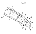
FIG. 2 is a partial cross-sectional view of a combustor assembly and transition piece of the turbomachine ofFIG. 1 ; -
FIG. 3 is a perspective view of the transition piece ofFIG. 2 ; -
FIG. 4 is a plan view of a fluid injector having an active control element in accordance with an exemplary embodiment; -
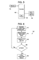
FIG. 5 is a block diagram illustrating a controller coupled to the active control element ofFIG. 4 ; and -
FIG. 6 is a flow chart illustrating a method of controlling the active control element ofFIG. 4 . - The detailed description explains embodiments of the invention, together with advantages and features, by way of example with reference to the drawings.
- With reference to
FIGs. 1 and2 , a turbomachine in accordance with an exemplary embodiment is indicated generally at 2. Turbomachine 2 includes a compressor portion 4 operatively connected to aturbine portion 6 through a common compressor/turbine shaft 8. Compressor portion 4 is also fluidly connected toturbine portion 6 through acombustor assembly 12.Combustor assembly 12 includes one or more circumferentially spacedcombustors 14 arranged in a can-annular array. Of course it should be understood thatcombustor assembly 12 may also include other combustor arrangements.Combustor 14 is fluidly connected toturbine portion 6 through atransition piece 20. With this arrangement air from compressor portion 4 is mixed with fuel to form a combustible mixture. The combustible mixture is combusted within acombustion chamber 30 ofcombustor 14 forming hot gases. The hot gases flow fromcombustor 14 to a first stage (not shown) ofturbine portion 6. -
Transition piece 20 includes abody 32 having afirst end 35 that extends to asecond end 36 through anintermediate portion 38.First end 35 is coupled tocombustor 14 whilesecond end 36 connects withturbine portion 6 through aframe element 39.Intermediate portion 38 includes anouter surface 40 and aninner surface 43.Inner surface 43 defines aflow duct 50 that extends between first andsecond ends Transition piece 20 includes a plurality of dilution openings 54-60 (FIGs. 2 and3 ) formed inintermediate portion 38. Dilution openings 54-60 extend throughbody 32 to fluidly connectflow duct 50 with an external flow area (not separately labeled). Each dilution opening 54-60 includes a dimension, for example a diameter, which is selectively adjusted to control fluid flow passing intoflow duct 50. More specifically, compressed air from compressor portion 4 flowing overouter surface 40 may pass through dilution openings 54-60 intoflow duct 50 to mix with the hot gases fromcombustor 14. The addition of the compressed air conditions the hot gas to achieve a desired temperature profile as will be detailed more fully below. The desired temperature profile is selected to enhance an over all operational life of turbine blades while, at the same time, maintaining turbomachine efficiency. - In accordance with one aspect of the exemplary embodiment,
transition piece 20 is provided with a plurality offluid injectors 70 such as shown inFIG. 4 , that selectively control the dimension of respective ones of dilution openings 54-60.Fluid injector 70 includes abody 74 having acentral passage 80.Central passage 80 includes aninlet 83 and anoutlet 85.Inlet 83 is exposed to compressed air flowing overouter surface 40 andoutlet 85 is arranged withinflow duct 50.Central passage 80 is provided with anactive control element 90 that is selectively controlled to adjust a flow rate of compressed air passing through respective ones of dilution openings 54-60. - In accordance with one aspect of the exemplary embodiment,
active control element 90 takes the form of a shaped memory alloy (SMA) actuator. Shaped memory alloys change shape when exposed to heat or when actively heated, and return to an original shape as the heat is removed. In accordance with yet another aspect of the exemplary embodiment,active control element 90 takes the form of a micro-electro-mechanical actuator that employs a micro electro-mechanical systems (MEMS) element to control fluid flow passing throughcentral passage 80. In accordance with still another aspect of the exemplary embodiment,active control element 90 takes the form of a micro optical-mechanical (MOM) or a micro optical-electro-mechanical (MOEM) actuator that is controlled by light through, for example fiber optic cables. In accordance with still another aspect of the exemplary embodiment,active control element 90 takes the form of a piezoelectric actuator. - In accordance with another aspect of the exemplary embodiment,
active control element 90 is operatively coupled to acontroller 100 as shown inFIG. 5 .Controller 100 includes a central processing unit (CPU) 104 and is also coupled to one ormore sensors 110 provided in various portions of turbomachine 2.Sensors 110 include one or more of a micro-electro-mechanical system (MEMS) sensor, a piezoelectric sensor, a transducer, and the like.Sensors 110 provide input tocontroller 100 of one or more operating parameters of turbomachine 2. The one or more operating parameters include a temperature profile of the hot or combustion gases flowing throughflow duct 50.Controller 100 determines a desired temperature profile for the hot gases and, if conditioning is warranted, signalsactive control element 90 to establish a desired flow rate of compressor gases intoflow duct 50. - A method of operating turbomachine 2 and, more specifically, controlling a temperature profile of gases flowing through
flow duct 50 is indicated at 140 inFIG. 6 .Controller 100 determines a desired temperature profile (DTP) of combustion gases flowing throughflow duct 50 as shown inblock 142.Controller 100 employs inputs fromsensors 110 and a stored algorithm to select the DTP.Controller 100 also measures an actual temperature profile (ATP) of the gases flowing throughflow duct 50 as shown in block 144.Controller 100 compares the DTP with the ATP inblock 146. If the DTP is the same as or within a desired range, for example 5% of the ATP, no action is taken as seen onblock 148. If, however it is determined inblock 148 that the DTP does not equal or fall within the desired range of the ATP,controller 100 signalsactive control element 90 to adjust the dimension ofcentral passage 80 to control an amount of compressor air entering intoflow duct 50 to mix with and condition the hot gases fromcombustor 14 to achieve the DTP as seen inblock 150. Adjusting the dimension ofcentral passage 80 includes increasing the dimension ofcentral passage 80 to increase compressor air intoflow duct 50 and decreasing the dimension ofcentral passage 80 to reduce the amount of compressor air passing intoflow duct 50. - At this point it should be understood that the exemplary embodiments provide a system and method for controlling fluid flow into a transition piece to condition gases flowing from a combustor to a turbine portion of a turbomachine. It should be understood that while shown and described as being formed as part of a fluid injector, the active control element can be mounted directly into one or more of the dilution openings. Also, it should be appreciated that while various examples of active control elements and sensors were described and claimed in connection with the exemplary embodiment, other types of active control elements and sensors may also be employed.
- While the invention has been described in detail in connection with only a limited number of embodiments, it should be readily understood that the invention is not limited to such disclosed embodiments. Rather, the invention can be modified to incorporate any number of variations, alterations, substitutions or equivalent arrangements not heretofore described, but which are commensurate with the spirit and scope of the invention. Additionally, while various embodiments of the invention have been described, it is to be understood that aspects of the invention may include only some of the described embodiments. Accordingly, the invention is not to be seen as limited by the foregoing description, but is only limited by the scope of the appended claims.
- Various aspects and embodiments of the present invention are defined by the following numbered clauses:
- 1. A transition piece for a gas turbomachine comprising:
- a body having an outer surface and an inner surface that defines a flow duct;
- a plurality of openings extending through the body; and
- an active control element provided at one or more of the plurality of openings, the active control element being configured and disposed to selectively establishing a dimension of the one or more of the plurality of openings.
- 2. The transition piece according to clause, further comprising: a fluid injector positioned in the one or more of the plurality of openings, the active control element being provided in the fluid injector.
- 3. The transition piece according to any preceding clause, further comprising: a controller operatively connected to the active control element, the controller being configured and disposed to adjust the active control element to establish a desired dimension of the one or more of the plurality of openings.
- 4. The transition piece according to any preceding clause, further comprising: one or more sensors operatively connected to the controller, the controller being configured and disposed to establish the desired dimension of the one or more of the plurality of openings based on an operating parameter sensed by the one or more sensors.
- 5. The transition piece according to any preceding clause, wherein the one or more sensors comprises a micro-electro-mechanical system (MEMS) sensor.
- 6. The transition piece according to any preceding clause, wherein the one or more sensors comprises a piezoelectric sensor.
- 7. The transition piece according to any preceding clause, wherein the active control element comprises a shaped memory alloy actuator.
- 8. The transition piece according to any preceding clause, wherein the active control element comprises a micro-electro-mechanical system (MEMS) actuator.
- 9. The transition piece according to any preceding clause, wherein the active control element comprises one of a micro-optical mechanical system (MOMS) and a micro-optical electro-mechanical system (MOEMS) actuator.
- 10. The transition piece according to any preceding clause, wherein the active control element comprises a piezoelectric actuator.
- 11. A turbomachine comprising:
- a compressor portion;
- a turbine portion;
- a combustor assembly fluidically connected to the compressor portion and the turbine portion; and
- a transition piece linking the combustor assembly and the turbine portion, the transition piece comprising:
- a body having an outer surface and an inner surface that defines a flow duct;
- a plurality of openings extending through the body; and
- an active control element provided at one or more of the plurality of openings, the active control element being configured and disposed to selectively establish a dimension of the one or more of the plurality of openings.
- 12. The turbomachine according to any preceding clause, further comprising: a fluid injector positioned in the one or more of the plurality of openings, the active control element being provided in the fluid injector.
- 13. The turbomachine according to any preceding clause, further comprising: a controller operatively connected to the active control element, the controller being configured and disposed to adjust the active control element to establish a desired dimension of the one or more of the plurality of openings.
- 14. The turbomachine according to any preceding clause, further comprising: one or more sensors operatively connected to the controller, the controller being configured and disposed to establish the desired dimension of the one or more of the plurality of openings based on an operating parameter sensed by the one or more sensors.
- 15. The turbomachine according to any preceding clause, wherein the active control element comprises one of a shaped memory alloy actuator, a micro-electro-mechanical system (MEMS) actuator, a micro-optical mechanical system (MOMS) actuator, a micro-optical electro-mechanical system (MOEMS) actuator, and a piezoelectric actuator.
- 16. A method of operating a turbomachine comprising:
- combusting fuel and air in a combustion chamber to form combustion gases;
- guiding the combustion gases through a transition piece into a turbine portion of a turbomachine;
- directing compressor air over an outer surface of the transition piece;
- passing the compressor air through one or more dilution openings formed in the transition piece to mix with the combustion gases; and
- signaling an active control element associated with at least one of the one or more dilution openings to control a flow rate of the compressor air.
- 17. The method of any preceding clause, further comprising: sensing an operating parameter of the turbomachine; and
signaling the active control element to control the flow rate of the compressor air based on the operating parameter of the turbomachine. - 18. The method of any preceding clause, further comprising: controlling the flow rate of the compressor air to adjust a temperature profile of the combustion gases.
- 19. The method of any preceding clause, wherein signaling the active control element comprises adjusting a dimension of the one or more dilution openings.
- 20. The method of any preceding clause, wherein adjusting a dimension of the one or more dilution openings comprises actuating one of a one of a shaped memory alloy actuator, a micro-electro-mechanical system (MEMS) actuator, a micro-optical mechanical system (MOMS) actuator, a micro-optical electro-mechanical system (MOEMS) actuator, and a piezoelectric actuator.
Claims (15)
- A transition piece (20) for a gas turbomachine (2) comprising:a body (32) having an outer surface (40) and an inner surface (43) that defines a flow duct (50);a plurality of openings (54-60) extending through the body (32); andan active control element (90) provided at one or more of the plurality of openings (54-60), the active control element (90) being configured and disposed to selectively establishing a dimension of the one or more of the plurality of openings (54-60).
- The transition piece (20) according to claim 1, further comprising: a fluid injector (70) positioned in the one or more of the plurality of openings (54-60), the active control element (90) being provided in the fluid injector (70).
- The transition piece (20) according to any preceding claim, further comprising: a controller (100) operatively connected to the active control element (90), the controller (100) being configured and disposed to adjust the active control element (90) to establish a desired dimension of the one or more of the plurality of openings(54-60).
- The transition piece (20) according to claim 3, further comprising: one or more sensors (110) operatively connected to the controller (100), the controller (100) being configured and disposed to establish the desired dimension of the one or more of the plurality of openings (54-60) based on an operating parameter sensed by the one or more sensors (110).
- The transition piece (20) according to claim 4, wherein the one or more sensors (110) comprises a micro-electro-mechanical system (MEMS) sensor.
- The transition piece (20) according to claim 4 or claim 5, wherein the one or more sensors (110) comprises a piezoelectric sensor.
- The transition piece (20) according to any preceding claim, wherein the active control element (90) comprises a shaped memory alloy actuator.
- The transition piece (20) according to any preceding claim, wherein the active control element (90) comprises a micro-electro-mechanical system (MEMS) actuator.
- The transition piece (20) according to any preceding claim, wherein the active control element (90) comprises one of a micro-optical mechanical system (MOMS) and a micro-optical electro-mechanical system (MOEMS) actuator.
- The transition piece (20) according to any preceding claim, wherein the active control element (90) comprises a piezoelectric actuator.
- A turbomachine (2) comprising:a compressor portion (4);a turbine portion (6);a combustor assembly (12) fluidically connected to the compressor portion (4) and the turbine portion (6); anda transition piece linking the combustor assembly and the turbine portion, the transition piece comprising:a body (32) having an outer surface (40) and an inner surface (43) that defines a flow duct (50);a plurality of openings (54-60) extending through the body (32); andan active control element (90) provided at one or more of the plurality of openings (54-60), the active control element (90) being configured and disposed to selectively establish a dimension of the one or more of the plurality of openings (54-60).
- The turbomachine (2) according to claim 11, further comprising: a fluid injector (70) positioned in the one or more of the plurality of openings (54-60), the active control element (90) being provided in the fluid injector (70).
- The turbomachine (2) according to claim 11 or claim 12, further comprising: a controller (100) operatively connected to the active control element (90), the controller (100) being configured and disposed to adjust the active control element (90) to establish a desired dimension of the one or more of the plurality of openings (54-60).
- The turbomachine (2) according to claim 13, further comprising: one or more sensors (110) operatively connected to the controller (100), the controller (100) being configured and disposed to establish the desired dimension of the one or more of the plurality of openings (54-60) based on an operating parameter sensed by the one or more sensors (110).
- The turbomachine (2) according to any of claims 11 to 14, wherein the active control element (90) comprises one of a shaped memory alloy actuator, a micro-electro-mechanical system (MEMS) actuator, a micro-optical mechanical system (MOMS) actuator, a micro-optical electro-mechanical system (MOEMS) actuator, and a piezoelectric actuator.
Applications Claiming Priority (1)
| Application Number | Priority Date | Filing Date | Title |
|---|---|---|---|
| US13/489,776 US20130327055A1 (en) | 2012-06-06 | 2012-06-06 | Transition piece for a gas turbomachine |
Publications (1)
| Publication Number | Publication Date |
|---|---|
| EP2672069A2 true EP2672069A2 (en) | 2013-12-11 |
Family
ID=48539030
Family Applications (1)
| Application Number | Title | Priority Date | Filing Date |
|---|---|---|---|
| EP13170418.1A Withdrawn EP2672069A2 (en) | 2012-06-06 | 2013-06-04 | Transition piece for a gas turbomachine |
Country Status (5)
| Country | Link |
|---|---|
| US (1) | US20130327055A1 (en) |
| EP (1) | EP2672069A2 (en) |
| JP (1) | JP2013253768A (en) |
| CN (1) | CN103470377A (en) |
| RU (1) | RU2013125742A (en) |
Cited By (1)
| Publication number | Priority date | Publication date | Assignee | Title |
|---|---|---|---|---|
| CN116624897A (en) * | 2023-05-24 | 2023-08-22 | 沈阳航空航天大学 | Combustion chamber and method for suppressing oscillating combustion based on 4D printing technology |
Families Citing this family (1)
| Publication number | Priority date | Publication date | Assignee | Title |
|---|---|---|---|---|
| US20160178199A1 (en) * | 2014-12-17 | 2016-06-23 | United Technologies Corporation | Combustor dilution hole active heat transfer control apparatus and system |
Family Cites Families (2)
| Publication number | Priority date | Publication date | Assignee | Title |
|---|---|---|---|---|
| GB0319329D0 (en) * | 2003-08-16 | 2003-09-17 | Rolls Royce Plc | Variable geometry combustor |
| US7677045B2 (en) * | 2006-04-14 | 2010-03-16 | Power Systems Mfg., Llc | Gas turbine transition duct |
-
2012
- 2012-06-06 US US13/489,776 patent/US20130327055A1/en not_active Abandoned
-
2013
- 2013-06-03 JP JP2013116558A patent/JP2013253768A/en active Pending
- 2013-06-04 EP EP13170418.1A patent/EP2672069A2/en not_active Withdrawn
- 2013-06-05 RU RU2013125742/06A patent/RU2013125742A/en not_active Application Discontinuation
- 2013-06-06 CN CN2013102239864A patent/CN103470377A/en active Pending
Non-Patent Citations (1)
| Title |
|---|
| None |
Cited By (1)
| Publication number | Priority date | Publication date | Assignee | Title |
|---|---|---|---|---|
| CN116624897A (en) * | 2023-05-24 | 2023-08-22 | 沈阳航空航天大学 | Combustion chamber and method for suppressing oscillating combustion based on 4D printing technology |
Also Published As
| Publication number | Publication date |
|---|---|
| RU2013125742A (en) | 2014-12-10 |
| US20130327055A1 (en) | 2013-12-12 |
| JP2013253768A (en) | 2013-12-19 |
| CN103470377A (en) | 2013-12-25 |
Similar Documents
| Publication | Publication Date | Title |
|---|---|---|
| EP2236760B1 (en) | Thermally decoupled can-annular transition piece | |
| US9810070B2 (en) | Turbine rotor blade for a turbine section of a gas turbine | |
| EP1854961A2 (en) | Clearance control apparatus | |
| US20140255145A1 (en) | Systems and Methods for Providing a Flow of Purge Air and an Adjustable Flow of Cooling Air in a Gas Turbine Application | |
| US20140373504A1 (en) | Gas turbine having an exhaust gas diffuser and supporting fins | |
| US20170350269A1 (en) | Passive clearance control sysem for gas turbomachine | |
| US9175604B2 (en) | Gas turbine engine with high and intermediate temperature compressed air zones | |
| CN103485841A (en) | Active control device and method of bucket cooling supply for turbine | |
| WO2014143236A1 (en) | Turbine vane cooling system, corresponding gas turbine engine and operating method | |
| US10502071B2 (en) | Controlling cooling flow in a cooled turbine vane or blade using an impingement tube | |
| EP2581664A1 (en) | Annular Flow Conditioning Member for Gas Turbomachine Combustor Assembly | |
| KR100785546B1 (en) | Flame temperature control and regulation system of single-shaft gas turbine | |
| US9127558B2 (en) | Turbomachine including horizontal joint heating and method of controlling tip clearance in a gas turbomachine | |
| EP2672069A2 (en) | Transition piece for a gas turbomachine | |
| EP2982846A1 (en) | Turbomachine system including an inlet bleed heat system and method of operating a turbomachine at part load | |
| JP2009144706A5 (en) | ||
| CN107345488B (en) | Turbine including clearance control system | |
| EP2672063A2 (en) | Turbomachine bucket assembly, corresponding turbomachine and method of cooling a turbomachine bucket assembly | |
| US9435219B2 (en) | Gas turbine inlet system and method | |
| CN109416180B (en) | Combustor assembly for use in a turbine engine and method of assembling the same | |
| WO2015069125A1 (en) | Turbomachine exhaust frame | |
| ITMI20130089A1 (en) | GAS TURBINE PLANT FOR THE PRODUCTION OF ELECTRICITY AND METHOD TO OPERATE THE PLANT | |
| US20160312649A1 (en) | High performance robust gas turbine exhaust with variable (adaptive) exhaust diffuser geometry |
Legal Events
| Date | Code | Title | Description |
|---|---|---|---|
| PUAI | Public reference made under article 153(3) epc to a published international application that has entered the european phase |
Free format text: ORIGINAL CODE: 0009012 |
|
| AK | Designated contracting states |
Kind code of ref document: A2 Designated state(s): AL AT BE BG CH CY CZ DE DK EE ES FI FR GB GR HR HU IE IS IT LI LT LU LV MC MK MT NL NO PL PT RO RS SE SI SK SM TR |
|
| AX | Request for extension of the european patent |
Extension state: BA ME |
|
| STAA | Information on the status of an ep patent application or granted ep patent |
Free format text: STATUS: THE APPLICATION IS DEEMED TO BE WITHDRAWN |
|
| 18D | Application deemed to be withdrawn |
Effective date: 20160105 |