EP2671795A1 - Composite material structure and aircraft wing provided therewith - Google Patents
Composite material structure and aircraft wing provided therewith Download PDFInfo
- Publication number
- EP2671795A1 EP2671795A1 EP12741802.8A EP12741802A EP2671795A1 EP 2671795 A1 EP2671795 A1 EP 2671795A1 EP 12741802 A EP12741802 A EP 12741802A EP 2671795 A1 EP2671795 A1 EP 2671795A1
- Authority
- EP
- European Patent Office
- Prior art keywords
- composite material
- wing
- structure member
- panel
- section
- Prior art date
- Legal status (The legal status is an assumption and is not a legal conclusion. Google has not performed a legal analysis and makes no representation as to the accuracy of the status listed.)
- Granted
Links
- 239000002131 composite material Substances 0.000 title claims abstract description 42
- 239000011151 fibre-reinforced plastic Substances 0.000 claims abstract description 13
- 229920002430 Fibre-reinforced plastic Polymers 0.000 claims abstract description 12
- 239000013585 weight reducing agent Substances 0.000 abstract 1
- 238000000034 method Methods 0.000 description 10
- 239000004918 carbon fiber reinforced polymer Substances 0.000 description 8
- 238000010008 shearing Methods 0.000 description 8
- 239000000463 material Substances 0.000 description 6
- 230000003014 reinforcing effect Effects 0.000 description 6
- 230000006835 compression Effects 0.000 description 5
- 238000007906 compression Methods 0.000 description 5
- 230000002093 peripheral effect Effects 0.000 description 5
- 238000007689 inspection Methods 0.000 description 4
- 239000000853 adhesive Substances 0.000 description 3
- 230000001070 adhesive effect Effects 0.000 description 3
- 230000002787 reinforcement Effects 0.000 description 3
- 229910000838 Al alloy Inorganic materials 0.000 description 2
- 229920000049 Carbon (fiber) Polymers 0.000 description 2
- 229910001069 Ti alloy Inorganic materials 0.000 description 2
- 239000004917 carbon fiber Substances 0.000 description 2
- 230000000694 effects Effects 0.000 description 2
- 239000000835 fiber Substances 0.000 description 2
- 239000011152 fibreglass Substances 0.000 description 2
- 239000012530 fluid Substances 0.000 description 2
- 239000000446 fuel Substances 0.000 description 2
- 239000002828 fuel tank Substances 0.000 description 2
- 238000012423 maintenance Methods 0.000 description 2
- 239000007769 metal material Substances 0.000 description 2
- VNWKTOKETHGBQD-UHFFFAOYSA-N methane Chemical compound C VNWKTOKETHGBQD-UHFFFAOYSA-N 0.000 description 2
- 229920006231 aramid fiber Polymers 0.000 description 1
- 238000007789 sealing Methods 0.000 description 1
Images




Classifications
-
- B—PERFORMING OPERATIONS; TRANSPORTING
- B64—AIRCRAFT; AVIATION; COSMONAUTICS
- B64C—AEROPLANES; HELICOPTERS
- B64C3/00—Wings
- B64C3/26—Construction, shape, or attachment of separate skins, e.g. panels
-
- B—PERFORMING OPERATIONS; TRANSPORTING
- B32—LAYERED PRODUCTS
- B32B—LAYERED PRODUCTS, i.e. PRODUCTS BUILT-UP OF STRATA OF FLAT OR NON-FLAT, e.g. CELLULAR OR HONEYCOMB, FORM
- B32B15/00—Layered products comprising a layer of metal
- B32B15/04—Layered products comprising a layer of metal comprising metal as the main or only constituent of a layer, which is next to another layer of the same or of a different material
- B32B15/08—Layered products comprising a layer of metal comprising metal as the main or only constituent of a layer, which is next to another layer of the same or of a different material of synthetic resin
-
- B—PERFORMING OPERATIONS; TRANSPORTING
- B32—LAYERED PRODUCTS
- B32B—LAYERED PRODUCTS, i.e. PRODUCTS BUILT-UP OF STRATA OF FLAT OR NON-FLAT, e.g. CELLULAR OR HONEYCOMB, FORM
- B32B15/00—Layered products comprising a layer of metal
- B32B15/14—Layered products comprising a layer of metal next to a fibrous or filamentary layer
-
- B—PERFORMING OPERATIONS; TRANSPORTING
- B32—LAYERED PRODUCTS
- B32B—LAYERED PRODUCTS, i.e. PRODUCTS BUILT-UP OF STRATA OF FLAT OR NON-FLAT, e.g. CELLULAR OR HONEYCOMB, FORM
- B32B15/00—Layered products comprising a layer of metal
- B32B15/20—Layered products comprising a layer of metal comprising aluminium or copper
-
- B—PERFORMING OPERATIONS; TRANSPORTING
- B32—LAYERED PRODUCTS
- B32B—LAYERED PRODUCTS, i.e. PRODUCTS BUILT-UP OF STRATA OF FLAT OR NON-FLAT, e.g. CELLULAR OR HONEYCOMB, FORM
- B32B27/00—Layered products comprising a layer of synthetic resin
- B32B27/06—Layered products comprising a layer of synthetic resin as the main or only constituent of a layer, which is next to another layer of the same or of a different material
- B32B27/08—Layered products comprising a layer of synthetic resin as the main or only constituent of a layer, which is next to another layer of the same or of a different material of synthetic resin
-
- B—PERFORMING OPERATIONS; TRANSPORTING
- B32—LAYERED PRODUCTS
- B32B—LAYERED PRODUCTS, i.e. PRODUCTS BUILT-UP OF STRATA OF FLAT OR NON-FLAT, e.g. CELLULAR OR HONEYCOMB, FORM
- B32B3/00—Layered products comprising a layer with external or internal discontinuities or unevennesses, or a layer of non-planar shape; Layered products comprising a layer having particular features of form
- B32B3/10—Layered products comprising a layer with external or internal discontinuities or unevennesses, or a layer of non-planar shape; Layered products comprising a layer having particular features of form characterised by a discontinuous layer, i.e. formed of separate pieces of material
-
- B—PERFORMING OPERATIONS; TRANSPORTING
- B32—LAYERED PRODUCTS
- B32B—LAYERED PRODUCTS, i.e. PRODUCTS BUILT-UP OF STRATA OF FLAT OR NON-FLAT, e.g. CELLULAR OR HONEYCOMB, FORM
- B32B3/00—Layered products comprising a layer with external or internal discontinuities or unevennesses, or a layer of non-planar shape; Layered products comprising a layer having particular features of form
- B32B3/10—Layered products comprising a layer with external or internal discontinuities or unevennesses, or a layer of non-planar shape; Layered products comprising a layer having particular features of form characterised by a discontinuous layer, i.e. formed of separate pieces of material
- B32B3/14—Layered products comprising a layer with external or internal discontinuities or unevennesses, or a layer of non-planar shape; Layered products comprising a layer having particular features of form characterised by a discontinuous layer, i.e. formed of separate pieces of material characterised by a face layer formed of separate pieces of material which are juxtaposed side-by-side
-
- B—PERFORMING OPERATIONS; TRANSPORTING
- B32—LAYERED PRODUCTS
- B32B—LAYERED PRODUCTS, i.e. PRODUCTS BUILT-UP OF STRATA OF FLAT OR NON-FLAT, e.g. CELLULAR OR HONEYCOMB, FORM
- B32B3/00—Layered products comprising a layer with external or internal discontinuities or unevennesses, or a layer of non-planar shape; Layered products comprising a layer having particular features of form
- B32B3/26—Layered products comprising a layer with external or internal discontinuities or unevennesses, or a layer of non-planar shape; Layered products comprising a layer having particular features of form characterised by a particular shape of the outline of the cross-section of a continuous layer; characterised by a layer with cavities or internal voids ; characterised by an apertured layer
- B32B3/263—Layered products comprising a layer with external or internal discontinuities or unevennesses, or a layer of non-planar shape; Layered products comprising a layer having particular features of form characterised by a particular shape of the outline of the cross-section of a continuous layer; characterised by a layer with cavities or internal voids ; characterised by an apertured layer characterised by a layer having non-uniform thickness
-
- B—PERFORMING OPERATIONS; TRANSPORTING
- B32—LAYERED PRODUCTS
- B32B—LAYERED PRODUCTS, i.e. PRODUCTS BUILT-UP OF STRATA OF FLAT OR NON-FLAT, e.g. CELLULAR OR HONEYCOMB, FORM
- B32B3/00—Layered products comprising a layer with external or internal discontinuities or unevennesses, or a layer of non-planar shape; Layered products comprising a layer having particular features of form
- B32B3/26—Layered products comprising a layer with external or internal discontinuities or unevennesses, or a layer of non-planar shape; Layered products comprising a layer having particular features of form characterised by a particular shape of the outline of the cross-section of a continuous layer; characterised by a layer with cavities or internal voids ; characterised by an apertured layer
- B32B3/266—Layered products comprising a layer with external or internal discontinuities or unevennesses, or a layer of non-planar shape; Layered products comprising a layer having particular features of form characterised by a particular shape of the outline of the cross-section of a continuous layer; characterised by a layer with cavities or internal voids ; characterised by an apertured layer characterised by an apertured layer, the apertures going through the whole thickness of the layer, e.g. expanded metal, perforated layer, slit layer regular cells B32B3/12
-
- B—PERFORMING OPERATIONS; TRANSPORTING
- B32—LAYERED PRODUCTS
- B32B—LAYERED PRODUCTS, i.e. PRODUCTS BUILT-UP OF STRATA OF FLAT OR NON-FLAT, e.g. CELLULAR OR HONEYCOMB, FORM
- B32B5/00—Layered products characterised by the non- homogeneity or physical structure, i.e. comprising a fibrous, filamentary, particulate or foam layer; Layered products characterised by having a layer differing constitutionally or physically in different parts
- B32B5/22—Layered products characterised by the non- homogeneity or physical structure, i.e. comprising a fibrous, filamentary, particulate or foam layer; Layered products characterised by having a layer differing constitutionally or physically in different parts characterised by the presence of two or more layers which are next to each other and are fibrous, filamentary, formed of particles or foamed
- B32B5/24—Layered products characterised by the non- homogeneity or physical structure, i.e. comprising a fibrous, filamentary, particulate or foam layer; Layered products characterised by having a layer differing constitutionally or physically in different parts characterised by the presence of two or more layers which are next to each other and are fibrous, filamentary, formed of particles or foamed one layer being a fibrous or filamentary layer
- B32B5/26—Layered products characterised by the non- homogeneity or physical structure, i.e. comprising a fibrous, filamentary, particulate or foam layer; Layered products characterised by having a layer differing constitutionally or physically in different parts characterised by the presence of two or more layers which are next to each other and are fibrous, filamentary, formed of particles or foamed one layer being a fibrous or filamentary layer another layer next to it also being fibrous or filamentary
-
- B—PERFORMING OPERATIONS; TRANSPORTING
- B32—LAYERED PRODUCTS
- B32B—LAYERED PRODUCTS, i.e. PRODUCTS BUILT-UP OF STRATA OF FLAT OR NON-FLAT, e.g. CELLULAR OR HONEYCOMB, FORM
- B32B7/00—Layered products characterised by the relation between layers; Layered products characterised by the relative orientation of features between layers, or by the relative values of a measurable parameter between layers, i.e. products comprising layers having different physical, chemical or physicochemical properties; Layered products characterised by the interconnection of layers
- B32B7/04—Interconnection of layers
-
- B—PERFORMING OPERATIONS; TRANSPORTING
- B32—LAYERED PRODUCTS
- B32B—LAYERED PRODUCTS, i.e. PRODUCTS BUILT-UP OF STRATA OF FLAT OR NON-FLAT, e.g. CELLULAR OR HONEYCOMB, FORM
- B32B7/00—Layered products characterised by the relation between layers; Layered products characterised by the relative orientation of features between layers, or by the relative values of a measurable parameter between layers, i.e. products comprising layers having different physical, chemical or physicochemical properties; Layered products characterised by the interconnection of layers
- B32B7/04—Interconnection of layers
- B32B7/08—Interconnection of layers by mechanical means
-
- B—PERFORMING OPERATIONS; TRANSPORTING
- B32—LAYERED PRODUCTS
- B32B—LAYERED PRODUCTS, i.e. PRODUCTS BUILT-UP OF STRATA OF FLAT OR NON-FLAT, e.g. CELLULAR OR HONEYCOMB, FORM
- B32B7/00—Layered products characterised by the relation between layers; Layered products characterised by the relative orientation of features between layers, or by the relative values of a measurable parameter between layers, i.e. products comprising layers having different physical, chemical or physicochemical properties; Layered products characterised by the interconnection of layers
- B32B7/04—Interconnection of layers
- B32B7/12—Interconnection of layers using interposed adhesives or interposed materials with bonding properties
- B32B7/14—Interconnection of layers using interposed adhesives or interposed materials with bonding properties applied in spaced arrangements, e.g. in stripes
-
- B—PERFORMING OPERATIONS; TRANSPORTING
- B64—AIRCRAFT; AVIATION; COSMONAUTICS
- B64C—AEROPLANES; HELICOPTERS
- B64C3/00—Wings
- B64C3/18—Spars; Ribs; Stringers
- B64C3/182—Stringers, longerons
-
- B—PERFORMING OPERATIONS; TRANSPORTING
- B64—AIRCRAFT; AVIATION; COSMONAUTICS
- B64C—AEROPLANES; HELICOPTERS
- B64C3/00—Wings
- B64C3/20—Integral or sandwich constructions
-
- B—PERFORMING OPERATIONS; TRANSPORTING
- B64—AIRCRAFT; AVIATION; COSMONAUTICS
- B64C—AEROPLANES; HELICOPTERS
- B64C3/00—Wings
- B64C3/34—Tanks constructed integrally with wings, e.g. for fuel or water
-
- B—PERFORMING OPERATIONS; TRANSPORTING
- B32—LAYERED PRODUCTS
- B32B—LAYERED PRODUCTS, i.e. PRODUCTS BUILT-UP OF STRATA OF FLAT OR NON-FLAT, e.g. CELLULAR OR HONEYCOMB, FORM
- B32B2260/00—Layered product comprising an impregnated, embedded, or bonded layer wherein the layer comprises an impregnation, embedding, or binder material
- B32B2260/02—Composition of the impregnated, bonded or embedded layer
- B32B2260/021—Fibrous or filamentary layer
-
- B—PERFORMING OPERATIONS; TRANSPORTING
- B32—LAYERED PRODUCTS
- B32B—LAYERED PRODUCTS, i.e. PRODUCTS BUILT-UP OF STRATA OF FLAT OR NON-FLAT, e.g. CELLULAR OR HONEYCOMB, FORM
- B32B2260/00—Layered product comprising an impregnated, embedded, or bonded layer wherein the layer comprises an impregnation, embedding, or binder material
- B32B2260/04—Impregnation, embedding, or binder material
- B32B2260/046—Synthetic resin
-
- B—PERFORMING OPERATIONS; TRANSPORTING
- B32—LAYERED PRODUCTS
- B32B—LAYERED PRODUCTS, i.e. PRODUCTS BUILT-UP OF STRATA OF FLAT OR NON-FLAT, e.g. CELLULAR OR HONEYCOMB, FORM
- B32B2262/00—Composition or structural features of fibres which form a fibrous or filamentary layer or are present as additives
- B32B2262/02—Synthetic macromolecular fibres
- B32B2262/0261—Polyamide fibres
- B32B2262/0269—Aromatic polyamide fibres
-
- B—PERFORMING OPERATIONS; TRANSPORTING
- B32—LAYERED PRODUCTS
- B32B—LAYERED PRODUCTS, i.e. PRODUCTS BUILT-UP OF STRATA OF FLAT OR NON-FLAT, e.g. CELLULAR OR HONEYCOMB, FORM
- B32B2262/00—Composition or structural features of fibres which form a fibrous or filamentary layer or are present as additives
- B32B2262/10—Inorganic fibres
- B32B2262/101—Glass fibres
-
- B—PERFORMING OPERATIONS; TRANSPORTING
- B32—LAYERED PRODUCTS
- B32B—LAYERED PRODUCTS, i.e. PRODUCTS BUILT-UP OF STRATA OF FLAT OR NON-FLAT, e.g. CELLULAR OR HONEYCOMB, FORM
- B32B2262/00—Composition or structural features of fibres which form a fibrous or filamentary layer or are present as additives
- B32B2262/10—Inorganic fibres
- B32B2262/106—Carbon fibres, e.g. graphite fibres
-
- B—PERFORMING OPERATIONS; TRANSPORTING
- B32—LAYERED PRODUCTS
- B32B—LAYERED PRODUCTS, i.e. PRODUCTS BUILT-UP OF STRATA OF FLAT OR NON-FLAT, e.g. CELLULAR OR HONEYCOMB, FORM
- B32B2307/00—Properties of the layers or laminate
- B32B2307/70—Other properties
- B32B2307/718—Weight, e.g. weight per square meter
-
- B—PERFORMING OPERATIONS; TRANSPORTING
- B32—LAYERED PRODUCTS
- B32B—LAYERED PRODUCTS, i.e. PRODUCTS BUILT-UP OF STRATA OF FLAT OR NON-FLAT, e.g. CELLULAR OR HONEYCOMB, FORM
- B32B2307/00—Properties of the layers or laminate
- B32B2307/70—Other properties
- B32B2307/732—Dimensional properties
-
- B—PERFORMING OPERATIONS; TRANSPORTING
- B32—LAYERED PRODUCTS
- B32B—LAYERED PRODUCTS, i.e. PRODUCTS BUILT-UP OF STRATA OF FLAT OR NON-FLAT, e.g. CELLULAR OR HONEYCOMB, FORM
- B32B2605/00—Vehicles
- B32B2605/18—Aircraft
-
- Y—GENERAL TAGGING OF NEW TECHNOLOGICAL DEVELOPMENTS; GENERAL TAGGING OF CROSS-SECTIONAL TECHNOLOGIES SPANNING OVER SEVERAL SECTIONS OF THE IPC; TECHNICAL SUBJECTS COVERED BY FORMER USPC CROSS-REFERENCE ART COLLECTIONS [XRACs] AND DIGESTS
- Y10—TECHNICAL SUBJECTS COVERED BY FORMER USPC
- Y10T—TECHNICAL SUBJECTS COVERED BY FORMER US CLASSIFICATION
- Y10T428/00—Stock material or miscellaneous articles
- Y10T428/19—Sheets or webs edge spliced or joined
- Y10T428/192—Sheets or webs coplanar
-
- Y—GENERAL TAGGING OF NEW TECHNOLOGICAL DEVELOPMENTS; GENERAL TAGGING OF CROSS-SECTIONAL TECHNOLOGIES SPANNING OVER SEVERAL SECTIONS OF THE IPC; TECHNICAL SUBJECTS COVERED BY FORMER USPC CROSS-REFERENCE ART COLLECTIONS [XRACs] AND DIGESTS
- Y10—TECHNICAL SUBJECTS COVERED BY FORMER USPC
- Y10T—TECHNICAL SUBJECTS COVERED BY FORMER US CLASSIFICATION
- Y10T428/00—Stock material or miscellaneous articles
- Y10T428/19—Sheets or webs edge spliced or joined
- Y10T428/192—Sheets or webs coplanar
- Y10T428/197—Sheets or webs coplanar with noncoplanar reinforcement
-
- Y—GENERAL TAGGING OF NEW TECHNOLOGICAL DEVELOPMENTS; GENERAL TAGGING OF CROSS-SECTIONAL TECHNOLOGIES SPANNING OVER SEVERAL SECTIONS OF THE IPC; TECHNICAL SUBJECTS COVERED BY FORMER USPC CROSS-REFERENCE ART COLLECTIONS [XRACs] AND DIGESTS
- Y10—TECHNICAL SUBJECTS COVERED BY FORMER USPC
- Y10T—TECHNICAL SUBJECTS COVERED BY FORMER US CLASSIFICATION
- Y10T428/00—Stock material or miscellaneous articles
- Y10T428/24—Structurally defined web or sheet [e.g., overall dimension, etc.]
- Y10T428/24008—Structurally defined web or sheet [e.g., overall dimension, etc.] including fastener for attaching to external surface
Definitions
- the present invention relates to a composite material structure including holes and an aircraft wing having the composite material structure.
- a composite material made of fiber reinforced plastics is widely used as a structure increased in strength and reduced in weight. Holes are sometimes formed in such a composite material for inspection and for access during assembly. When the holes are formed, since stress concentration occurs in the peripheral edge portions of the holes, it is necessary to increase the strength of the peripheral edge portions of the holes.
- PTL 1 described below discloses an invention for adding a reinforcing layer to increase thickness and increasing strength in order to reinforce the peripheral edge portions of access holes of an outer plate of an aircraft.
- the reinforcing layer described in PTL 1 is fixed to a base material by pins or stitches to prevent the reinforcing layer from peeling when the reinforcing layer receives a load.
- the invention described in PTL 1 has a problem in terms of productivity because a process for applying the pins or the stitches to the reinforcing layer when the reinforcing layer is added increases.
- a lower surface outer plate 103 of a wing 100 of an aircraft having a structure shown in Fig. 6 is known.
- a plurality of access holes 102 are formed in the center section in the width direction of the lower surface outer plate 103.
- the access holes 102 are used for inspection or during assembly of a fuel tank provided in the wing 100.
- Broken lines shown in the figure indicate contour lines of the wing 100 including a flap and a slat.
- a laminate for reinforcement 104 is stacked (padded up) on a base material laminate 106.
- the laminate for reinforcement 104 has a shape formed with a taper reduced in thickness further away from the access hole 102.
- a fixed thickness portion 104a located in the peripheral edge portion of the access hole 102 and having fixed thickness is enough. However, if only the fixed thickness portion 104a is formed, peeling occurs in an interface with the base material 106 when the fixed thickness portion 104a receives a load.
- the fixed thickness portion 104a is not only formed but also further extended to form a taper portion 104b and gradually increase thickness.
- the taper portion 104b is hatched to facilitate understanding.
- the taper portion 104b and the fixed thickness portion 104a are continuous and formed by the same stacked sheet.
- the process for applying the pins or the stitches described in PTL 1 is unnecessary.
- the taper portion 104b is originally unnecessary and is a cause of an increase in weight.
- the present invention has been devised in view of such circumstances and it is an object of the present invention to provide a composite material structure with holes enabled to be reduced in weight and an aircraft wing provided therewith.
- a composite material structure according to a first aspect of the present invention includes: a first structure member extending in one direction and formed as a composite material made of fiber reinforced plastics; a second structure member separated from the first structure member by a predetermined space, extending in the one direction, and formed as a composite material made of fiber reinforced plastics; and a panel provided between the first structure member and the second structure member and having a dimension in the one direction shorter than the first structure member and the second structure member.
- the panel is not movable from the first structure member side and from the second structure member side in an orthogonal direction substantially orthogonal to the one direction and set to be displaceable in the one direction and is removable.
- the panel Since the panel is removable, a hole formed after the panel is removed can be used for various kinds of work such as maintenance. In this way, a composite material structure with holes can be realized by the removable panel.
- the material of the panel fiber reinforced plastics is suitable. However, the material may be other materials. For example, a metal material such as a titanium alloy or an aluminum alloy can also be used.
- the composite material structure according to the first aspect may include a plurality of the panels.
- the panels may be continuously provided side by side over the one direction.
- the plurality of panels are continuously provided side by side over the one direction, it is possible to form a hole in an arbitrary position by removing the panel in an arbitrary position.
- a lower surface outer plate of a wing of an aircraft may be configured by the first structure member, the second structure member, and the panel.
- the lower surface outer plate configures a lower surface portion of a torque box that bears a load applied to the wing of the aircraft. Therefore, a tensile load is applied to the lower surface outer plate in the longitudinal direction of the wing during flight.
- the first structure member and the second structure member bear the tensile load.
- An access hole for performing inspection and the like of the inside of the torque box is provided in the wing.
- the hole since the hole is formed by removing the panel, the hole can be used as an access hole. Since the panel does not bear the tensile load, it is possible to provide the wing reduced in weight through reduction in thickness.
- the panel that does not bear the tensile load and the compression load and bears only the shearing load is adopted, it is possible to reduce weight of the panel by reducing thickness of the panel. Since the panel is removed to form the hole, it is possible to realize the composite material structure with holes.
- FIG. 1A a lower surface outer plate 3 of a wing 1 of an aircraft is shown.
- the lower surface outer plate 3 is formed by a composite material structure made of fiber reinforced plastics (FRP).
- Broken lines shown in the figure indicate contour lines of the wing 1 including a flap and a slat.
- the lower surface outer plate 3 is configured by three sections, i.e., a front section (a first structure member) 3a located on the front edge side of the wing 1, a center section 3b connected to the front section 3a, and a rear section (a second structure member) 3c connected to the center section 3b and located on the rear edge side of the wing 1.
- the front section 3a, the center section 3b, and the rear section 3c are divided on a division surface 4 extending in the longitudinal direction of the wing 1.
- the center section 3b is configured to a plurality of access panels 5 continuously arranged along the longitudinal direction of the wing 1 (one direction).
- the lower surface outer plate 3 forms a torque box having a box shape in conjunction with a front spar 20 and a rear spar 22, which are side surface outer plates, erected from both ends in the width direction of the lower surface outer plate 3 and an upper surface outer plate 24 that connects upper ends of the front spar 20 and the rear spar 22.
- the lower surface outer plate 3 bears a load of the wing 1.
- a plurality of stringers 26 are provided in the longitudinal direction of the wing 1.
- the stringers 26 are composite materials made of FRP like the lower surface outer plate 3 and the like.
- the respective stringers 26 are fixed to the inner surfaces of the lower surface outer plate 3 and the upper surface outer plate 24 and mainly bear a load in the longitudinal direction of the wing 1.
- ribs 28 are provided to divide an internal space of the wing 1 into a plurality of spaces in the longitudinal direction.
- the ribs 28 are formed in a plate shape extending over the width direction (a direction orthogonal to the longitudinal direction) of the wing 1.
- a plurality of ribs 28 are arranged at a predetermined interval in the longitudinal direction. As shown in Fig. 3 , the front and rear ends of the respective ribs 28 are respectively fixed to the front spar 20 and the rear spar 22 by predetermined fasteners 30 such as bolts and nuts.
- the front section 3a of the lower surface outer plate 3 is a composite material mainly formed of carbon fiber reinforced plastics (CFRP).
- the number of stacked layers of the composite material used in the front section 3a is determined by bearing strength.
- the rear section 3c of the lower surface outer plate 3 is a composite material mainly formed of carbon fiber reinforced plastics (CFRP).
- CFRP carbon fiber reinforced plastics
- the number of stacked layers of the composite material used in the rear section 3c is determined by bearing strength.
- the access panels 5 that configure the center section 3b of the lower surface outer plate 3 are composite materials mainly formed of carbon fiber reinforced plastics (CFRP).
- CFRP carbon fiber reinforced plastics
- the access panels 5 are removable and can be used as access holes (holes) 5 used during inspection, during assembly, and the like of a fuel tank provided in the wing 1. Consequently, the lower surface outer plate 3 of the wing 1 can be used as a structure member with holes.
- the access holes 5 are not formed in the front section 3a and the rear section 3c described above. As shown in Fig. 1B , the access panel 5 does not need to bear a load in the longitudinal direction of the wing 1 compared with the front section 3a and the rear section 3c. Therefore, the number of stacked layers is reduced to reduce thickness.
- a metal material such as a titanium alloy and an aluminum alloy may be used.
- FIG. 4 a longitudinal sectional view in B-B in Fig. 2 is shown.
- a method of attaching the access panels 5 in a connecting direction is shown.
- the access panels 5 are slidably (dispaceably) attached to a wing main body side (the side of the front section 3a and the side of the rear section 3c fixed to the wing main body). That is, an attachment structure in which a flange section 28a of the rib 28 on the wing main body side is clamped by the access panels 5 and clamp angles 40 is adopted.
- the access panels 5 are slidably attached to the ribs 28 (i.e., the wing main body side). Therefore, the access panels 5 do not bear a load even when a tensile load (or a compression load) is generated in the longitudinal direction of the wing 1 (in the figure, the left right direction).
- FIG. 5 A cross sectional view in C-C in Fig. 2 is shown in Fig. 5 .
- a method of attaching the access panel 5 and the front section 3a is shown.
- the access panel 5 is fixed to the wing main body side (the side of the front section 3a fixed to the wing main body) via the stringer 26.
- connection to the rear section 3c is the same.
- the stringer 26 and the front section 3a are fixed by fasteners 50 after being bonded in a bonding section 48.
- the fixing of the stringer 26 and the front section 3a may be by only bonding or only fasteners.
- a method of curing both of the stringer 26 and the front section 3a and thereafter bonding the stringer 26 and the front section 3a using an adhesive is used.
- an after-cure bonding method a co-bond method of interposing an adhesive between the stringer 26 after curing and the front section 3a before curing or between the stringer 26 before curing and the front section 3a after curing and thereafter applying temperature and/or pressure to integrally cure the stringer 26 and the front section 3a
- a co-cure method of interposing an adhesive between the stringer 26 before curing and the front section 3a before curing and thereafter applying temperature and/or pressure to integrally cure the stringer 26 and the front section 3a is used.
- the access panel 5 is fixed to the stringer 26 by flat head bolts 52.
- the flat head bolts 52 inserted from the lower surface side of the access panel 5 are screwed into dome nuts 54, whereby a flange section 26a and a seal retainer 56 of the stringer 26 clamped between the flat head bolts 52 and the dome nuts 54 are tightened.
- the dome nuts 54 are provided with a self-sealing function and can be fluid-tightly fixed.
- a seal tube 58 is provided between the seal retainer 56 and the access panel 5.
- an O ring 60 is provided between the lower surface of the flange section 26a of the stringer 26 and the access panel 5.
- the plate thickness of the front section and the rear section 3c is larger than the plate thickness in the structure shown in Fig. 6 .
- the wing as a whole, it is possible to sufficiently realize a reduction in weight.
- the access panels 5 are removable, holes formed after the access panels 5 are removed can be used as access holes for maintenance and the like. In this way, the wing formed as the composite material structure with holes can be realized by the removable access panels 5.
- the application to the lower surface outer plate 3 of the wing 1 is explained.
- the present invention is not limited to this and can be widely applied to composite material structures including holes.
- a configuration same as the lower surface outer plate 3 may be applied to an upper surface outer plate that configures a torque box in conjunction with the lower surface outer plate 3.
- CFRP carbon fiber reinforced plastics
- GFRP glass fiber reinforced plastics
- AFRP aramid fiber reinforced plastics
Landscapes
- Engineering & Computer Science (AREA)
- Mechanical Engineering (AREA)
- Aviation & Aerospace Engineering (AREA)
- Moulding By Coating Moulds (AREA)
- Laminated Bodies (AREA)
Abstract
Description
- The present invention relates to a composite material structure including holes and an aircraft wing having the composite material structure.
- In the fields of aircrafts, ships, vehicles, and the like, a composite material made of fiber reinforced plastics (FRP) is widely used as a structure increased in strength and reduced in weight. Holes are sometimes formed in such a composite material for inspection and for access during assembly. When the holes are formed, since stress concentration occurs in the peripheral edge portions of the holes, it is necessary to increase the strength of the peripheral edge portions of the holes.
-
PTL 1 described below discloses an invention for adding a reinforcing layer to increase thickness and increasing strength in order to reinforce the peripheral edge portions of access holes of an outer plate of an aircraft. The reinforcing layer described inPTL 1 is fixed to a base material by pins or stitches to prevent the reinforcing layer from peeling when the reinforcing layer receives a load. - Japanese Translation of
PCT international Application, Publication No. 2003-513821 - However, the invention described in
PTL 1 has a problem in terms of productivity because a process for applying the pins or the stitches to the reinforcing layer when the reinforcing layer is added increases. - As a method of not using such pins or stitches, a lower surface
outer plate 103 of awing 100 of an aircraft having a structure shown inFig. 6 is known. As shown inFig. 6A , a plurality ofaccess holes 102 are formed in the center section in the width direction of the lower surfaceouter plate 103. Theaccess holes 102 are used for inspection or during assembly of a fuel tank provided in thewing 100. Broken lines shown in the figure indicate contour lines of thewing 100 including a flap and a slat. - To increase the strength of the peripheral edge portions of the
access holes 102, as shown inFig. 6B , a laminate forreinforcement 104 is stacked (padded up) on abase material laminate 106. When viewed in section as shown inFig. 6B , the laminate forreinforcement 104 has a shape formed with a taper reduced in thickness further away from theaccess hole 102. To reinforce theaccess hole 102, afixed thickness portion 104a located in the peripheral edge portion of theaccess hole 102 and having fixed thickness is enough. However, if only thefixed thickness portion 104a is formed, peeling occurs in an interface with thebase material 106 when thefixed thickness portion 104a receives a load. To prevent the peeling, thefixed thickness portion 104a is not only formed but also further extended to form ataper portion 104b and gradually increase thickness. Note that, inFig. 6B , thetaper portion 104b is hatched to facilitate understanding. However, thetaper portion 104b and thefixed thickness portion 104a are continuous and formed by the same stacked sheet.
In the structure shown inFigs. 6A and 6B , the process for applying the pins or the stitches described inPTL 1 is unnecessary. However, from the viewpoint of only reinforcement of theaccess hole 102, thetaper portion 104b is originally unnecessary and is a cause of an increase in weight. - The present invention has been devised in view of such circumstances and it is an object of the present invention to provide a composite material structure with holes enabled to be reduced in weight and an aircraft wing provided therewith.
- In order to solve the problems, a composite material structure and an aircraft wing provided therewith of the present invention adopt the following solutions.
That is, a composite material structure according to a first aspect of the present invention includes: a first structure member extending in one direction and formed as a composite material made of fiber reinforced plastics; a second structure member separated from the first structure member by a predetermined space, extending in the one direction, and formed as a composite material made of fiber reinforced plastics; and a panel provided between the first structure member and the second structure member and having a dimension in the one direction shorter than the first structure member and the second structure member. The panel is not movable from the first structure member side and from the second structure member side in an orthogonal direction substantially orthogonal to the one direction and set to be displaceable in the one direction and is removable. - When a tensile load or a compression load is applied in the one direction of the composite material structure, since the panel is set to be displaceable in the one direction, only the first structure member and the second structure member bear the load. On the other hand, not only the first structure member and the second structure member but also the panel fixed in the orthogonal direction bear a load (a shearing load) in the orthogonal direction of the composite material structure. In this way, the panel bears only the shearing load and does not need to bear the tensile load and the compression load. Therefore, it is possible to reduce strength of the panel. That is, it is possible to reduce the thickness of the panel and realize a reduction in weight.
Since the panel is removable, a hole formed after the panel is removed can be used for various kinds of work such as maintenance. In this way, a composite material structure with holes can be realized by the removable panel.
As the material of the panel, fiber reinforced plastics is suitable. However, the material may be other materials. For example, a metal material such as a titanium alloy or an aluminum alloy can also be used. - Further, the composite material structure according to the first aspect may include a plurality of the panels. The panels may be continuously provided side by side over the one direction.
- Since the plurality of panels are continuously provided side by side over the one direction, it is possible to form a hole in an arbitrary position by removing the panel in an arbitrary position.
- Further, in the composite material structure according to the second aspect, a lower surface outer plate of a wing of an aircraft may be configured by the first structure member, the second structure member, and the panel.
- The lower surface outer plate configures a lower surface portion of a torque box that bears a load applied to the wing of the aircraft. Therefore, a tensile load is applied to the lower surface outer plate in the longitudinal direction of the wing during flight. The first structure member and the second structure member bear the tensile load. An access hole for performing inspection and the like of the inside of the torque box is provided in the wing. However, in the present invention, since the hole is formed by removing the panel, the hole can be used as an access hole.
Since the panel does not bear the tensile load, it is possible to provide the wing reduced in weight through reduction in thickness. - With the composite material structure and the aircraft wing provided therewith of the present invention, since the panel that does not bear the tensile load and the compression load and bears only the shearing load is adopted, it is possible to reduce weight of the panel by reducing thickness of the panel.
Since the panel is removed to form the hole, it is possible to realize the composite material structure with holes. -
- {
Fig. 1A} Fig. 1A is a plan view showing a lower surface outer plate of a wing of an aircraft according to an embodiment of a composite material structure of the present invention. - {
Fig. 1B} Fig. 1B is a longitudinal sectional view showing the lower surface outer plate of the wing of the aircraft according to the embodiment of the composite material structure of the present invention. - {
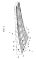
Fig. 2} Fig. 2 is a perspective view showing the lower surface outer plate and stringers that configure a part of the wing formed in a box structure. - {
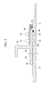
Fig. 3} Fig. 3 is a cross sectional view in A-A inFig. 2 . - {
Fig. 4} Fig. 4 is a longitudinal sectional view in B-B inFig. 2 . - {
Fig. 5} Fig. 5 is a cross sectional view in C-C inFig. 2 . - {
Fig. 6A} Fig. 6A is a plan view showing a lower surface outer plate of a conventional wing of an aircraft. - {
Fig. 6B} Fig. 6B is a longitudinal sectional view showing the lower surface outer plate of the conventional wing of the aircraft. - An embodiment of the present invention is explained below with reference to
Figs. 1 to 5 .
InFig. 1A , a lower surfaceouter plate 3 of awing 1 of an aircraft is shown. The lower surfaceouter plate 3 is formed by a composite material structure made of fiber reinforced plastics (FRP). Broken lines shown in the figure indicate contour lines of thewing 1 including a flap and a slat. - The lower surface
outer plate 3 is configured by three sections, i.e., a front section (a first structure member) 3a located on the front edge side of thewing 1, acenter section 3b connected to thefront section 3a, and a rear section (a second structure member) 3c connected to thecenter section 3b and located on the rear edge side of thewing 1. Thefront section 3a, thecenter section 3b, and therear section 3c are divided on adivision surface 4 extending in the longitudinal direction of thewing 1.
Thecenter section 3b is configured to a plurality ofaccess panels 5 continuously arranged along the longitudinal direction of the wing 1 (one direction). - As shown in
Figs. 2 and3 , the lower surfaceouter plate 3 forms a torque box having a box shape in conjunction with afront spar 20 and arear spar 22, which are side surface outer plates, erected from both ends in the width direction of the lower surfaceouter plate 3 and an upper surfaceouter plate 24 that connects upper ends of thefront spar 20 and therear spar 22. The lower surfaceouter plate 3 bears a load of thewing 1. - A plurality of
stringers 26 are provided in the longitudinal direction of thewing 1. Thestringers 26 are composite materials made of FRP like the lower surfaceouter plate 3 and the like. Therespective stringers 26 are fixed to the inner surfaces of the lower surfaceouter plate 3 and the upper surfaceouter plate 24 and mainly bear a load in the longitudinal direction of thewing 1.
On the inside of thewing 1 formed in the box structure,ribs 28 are provided to divide an internal space of thewing 1 into a plurality of spaces in the longitudinal direction. Theribs 28 are formed in a plate shape extending over the width direction (a direction orthogonal to the longitudinal direction) of thewing 1. A plurality ofribs 28 are arranged at a predetermined interval in the longitudinal direction. As shown inFig. 3 , the front and rear ends of therespective ribs 28 are respectively fixed to thefront spar 20 and therear spar 22 bypredetermined fasteners 30 such as bolts and nuts. - The
front section 3a of the lower surfaceouter plate 3 is a composite material mainly formed of carbon fiber reinforced plastics (CFRP). A ratio of orientation of carbon fiber is set to a normal degree used in a structure of an aircraft. For example, when an extending direction (the longitudinal direction) of thewing 1 is 0°, a plurality of sheets having respective fiber directions are stacked to configure the composite material such that the ratio is (0°, +45°, -45°, 90°)=(30%, 30%, 30%, 10%). The number of stacked layers of the composite material used in thefront section 3a is determined by bearing strength. - Like the
front section 3a, therear section 3c of the lower surfaceouter plate 3 is a composite material mainly formed of carbon fiber reinforced plastics (CFRP). Like thefront section 3a, a ratio of orientation of carbon fiber is set to a normal degree used in a structure of an aircraft. For example, when an extending direction of thewing 1 is 0°, a plurality of sheets having respective fiber directions are stacked to configure the composite material such that the ratio is (0°, +45°, -45°, 90°)=(30%, 30%, 30%, 10%). The number of stacked layers of the composite material used in therear section 3c is determined by bearing strength. - The
access panels 5 that configure thecenter section 3b of the lower surfaceouter plate 3 are composite materials mainly formed of carbon fiber reinforced plastics (CFRP).
Theaccess panels 5 are removable and can be used as access holes (holes) 5 used during inspection, during assembly, and the like of a fuel tank provided in thewing 1. Consequently, the lower surfaceouter plate 3 of thewing 1 can be used as a structure member with holes. The access holes 5 are not formed in thefront section 3a and therear section 3c described above.
As shown inFig. 1B , theaccess panel 5 does not need to bear a load in the longitudinal direction of thewing 1 compared with thefront section 3a and therear section 3c. Therefore, the number of stacked layers is reduced to reduce thickness.
As theaccess panel 5, a metal material such as a titanium alloy and an aluminum alloy may be used. - Next, a method of attaching the
access panels 5 is explained.
InFig. 4 , a longitudinal sectional view in B-B inFig. 2 is shown. In the figure, a method of attaching theaccess panels 5 in a connecting direction is shown. Theaccess panels 5 are slidably (dispaceably) attached to a wing main body side (the side of thefront section 3a and the side of therear section 3c fixed to the wing main body). That is, an attachment structure in which aflange section 28a of therib 28 on the wing main body side is clamped by theaccess panels 5 and clampangles 40 is adopted. Specifically,flat head bolts 42 are inserted from the lower surface side of theaccess panels 5 and screwed into the clamp angles 40 set in above the access panels 5 (in the torque box of the wing 1). Consequently, at rib side ends 40a of the clamp angles 40, spaces between the clamp angles 40 and theaccess panels 5 are narrowed to clamp theflange sections 28a of theribs 28. Note that O rings 44a and 44b are respectively provided on contact surfaces of the clamp angles 40 and theaccess panels 5 and contact surfaces of the clamp angles 40 and theflange sections 28a of theribs 28. Fluid tightness against fuel stored in the torque box of thewing 1 is secured by the O rings 44a and 44b.
In this way, theaccess panels 5 are slidably attached to the ribs 28 (i.e., the wing main body side). Therefore, theaccess panels 5 do not bear a load even when a tensile load (or a compression load) is generated in the longitudinal direction of the wing 1 (in the figure, the left right direction). - A cross sectional view in C-C in
Fig. 2 is shown inFig. 5 . In the figure, a method of attaching theaccess panel 5 and thefront section 3a is shown. Theaccess panel 5 is fixed to the wing main body side (the side of thefront section 3a fixed to the wing main body) via thestringer 26. Although not shown in the figure, connection to therear section 3c is the same.
Thestringer 26 and thefront section 3a are fixed byfasteners 50 after being bonded in abonding section 48. The fixing of thestringer 26 and thefront section 3a may be by only bonding or only fasteners. As the bonding, a method of curing both of thestringer 26 and thefront section 3a and thereafter bonding thestringer 26 and thefront section 3a using an adhesive (an after-cure bonding method) is used. Besides, for example, a co-bond method of interposing an adhesive between thestringer 26 after curing and thefront section 3a before curing or between thestringer 26 before curing and thefront section 3a after curing and thereafter applying temperature and/or pressure to integrally cure thestringer 26 and thefront section 3a or a co-cure method of interposing an adhesive between thestringer 26 before curing and thefront section 3a before curing and thereafter applying temperature and/or pressure to integrally cure thestringer 26 and thefront section 3a is used. - The
access panel 5 is fixed to thestringer 26 byflat head bolts 52. Specifically, theflat head bolts 52 inserted from the lower surface side of theaccess panel 5 are screwed intodome nuts 54, whereby aflange section 26a and aseal retainer 56 of thestringer 26 clamped between theflat head bolts 52 and thedome nuts 54 are tightened. Thedome nuts 54 are provided with a self-sealing function and can be fluid-tightly fixed. Aseal tube 58 is provided between theseal retainer 56 and theaccess panel 5. Further, anO ring 60 is provided between the lower surface of theflange section 26a of thestringer 26 and theaccess panel 5. Fluid tightness against the fuel stored in the torque box of thewing 1 is secured by thedome nuts 54, theseal tube 58, and theO ring 60.
In this way, theaccess panel 5 is fixed to the rib 28 (i.e., the wing main body side). Therefore, when a shearing load is generated in a direction orthogonal to the longitudinal direction of thewing 1, theaccess panel 5 can bear the load in the shearing direction. - Next, the function effects obtained when the
wing 1 including the configuration explained above is used are explained.
During flight, a load is applied to thewing 1 to displace the distal end of thewing 1 upward. Therefore, a tensile load is applied to the lower surfaceouter plate 3 of thewing 1 in the longitudinal direction of the wing 1 (the 0° direction). In this case, since theaccess panel 5 is set displaceably in the longitudinal direction, only thefront section 3a and therear section 3c bear the load. On the other hand, not only thefront section 3a and therear section 3c but also theaccess panels 5 bear a load (a shearing load) in an orthogonal direction orthogonal to the longitudinal direction. In this way, theaccess panels 5 bear only the shearing load and do not need to bear the tensile load and the compression load. Therefore, it is possible to reduce strength of theaccess panels 5. That is, it is possible to reduce the thickness of the panel to realize a reduction in weight.
For example, when a stress concentration factor around elliptical holes shown inFig. 6 is 2 and the strength of the structure shown inFig. 6 is 100, when it is taken into account that a ratio of a shearing load and a tensile load applied to the lower surfaceouter plate 3 of thewing 1 is 3:7, it is possible to reduce the plate thickness of theaccess panels 5 to about 15% according to the following equation:
Compared with the structure shown inFig. 6 , since only thefront section 3a and therear section 3c bear the tensile load, the plate thickness of the front section and therear section 3c is larger than the plate thickness in the structure shown inFig. 6 . However, as the wing as a whole, it is possible to sufficiently realize a reduction in weight. - Since the
access panels 5 are removable, holes formed after theaccess panels 5 are removed can be used as access holes for maintenance and the like. In this way, the wing formed as the composite material structure with holes can be realized by theremovable access panels 5. - Note that, in this embodiment, the application to the lower surface
outer plate 3 of thewing 1 is explained. However, the present invention is not limited to this and can be widely applied to composite material structures including holes.
For example, a configuration same as the lower surfaceouter plate 3 may be applied to an upper surface outer plate that configures a torque box in conjunction with the lower surfaceouter plate 3. - In the embodiment, carbon fiber reinforced plastics (CFRP) is mainly used. However, the present invention is not limited to this. For example, glass fiber reinforced plastics (GFRP) or aramid fiber reinforced plastics (AFRP) may be used.
-
- 1
- wing
- 3
- lower surface outer plate (composite material structure)
- 3a
- front section (adjacent structure member)
- 3b
- center section
- 3c
- rear section (adjacent structure member)
- 5
- panels (access panels)
Claims (4)
- A composite material structure comprising:a first structure member extending in one direction and formed as a composite material made of fiber reinforced plastics;a second structure member separated from the first structure member by a predetermined space, extending in the one direction, and formed as a composite material made of fiber reinforced plastics; anda panel provided between the first structure member and the second structure member and having a dimension in the one direction shorter than the first structure member and the second structure member,wherein the panel is not movable from the first structure member side and from the second structure member side in an orthogonal direction substantially orthogonal to the one direction and set to be displaceable in the one direction and is removable.
- The composite material structure according to claim 1, wherein the composite material structure includes a plurality of the panels, and
the panels are continuously provided side by side over the one direction. - The composite material structure according to claim 1 or 2, wherein a lower surface outer plate of a wing of an aircraft is configured by the first structure member, the second structure member, and the panel.
- An aircraft wing comprising the composite material structure according to claim 3.
Applications Claiming Priority (2)
| Application Number | Priority Date | Filing Date | Title |
|---|---|---|---|
| JP2011023155A JP5808112B2 (en) | 2011-02-04 | 2011-02-04 | Composite structure and aircraft main wing provided with the same |
| PCT/JP2012/051700 WO2012105416A1 (en) | 2011-02-04 | 2012-01-26 | Composite material structure and aircraft wing provided therewith |
Publications (3)
| Publication Number | Publication Date |
|---|---|
| EP2671795A1 true EP2671795A1 (en) | 2013-12-11 |
| EP2671795A4 EP2671795A4 (en) | 2018-01-03 |
| EP2671795B1 EP2671795B1 (en) | 2019-07-03 |
Family
ID=46602633
Family Applications (1)
| Application Number | Title | Priority Date | Filing Date |
|---|---|---|---|
| EP12741802.8A Active EP2671795B1 (en) | 2011-02-04 | 2012-01-26 | Composite material structure and aircraft wing provided therewith |
Country Status (5)
| Country | Link |
|---|---|
| US (1) | US9027881B2 (en) |
| EP (1) | EP2671795B1 (en) |
| JP (1) | JP5808112B2 (en) |
| CN (1) | CN103339028B (en) |
| WO (1) | WO2012105416A1 (en) |
Families Citing this family (11)
| Publication number | Priority date | Publication date | Assignee | Title |
|---|---|---|---|---|
| JP6004669B2 (en) | 2012-02-29 | 2016-10-12 | 三菱重工業株式会社 | Composite structure, aircraft wing and aircraft fuselage provided with the same, and method for manufacturing composite structure |
| US20140117022A1 (en) | 2012-10-30 | 2014-05-01 | The Boeing Company | Composite Structures Having Bondlines with Matched Electrical Conductivity |
| JP6093192B2 (en) * | 2013-01-25 | 2017-03-08 | 三菱航空機株式会社 | Aircraft fuselage panel, aircraft wing |
| US9849967B2 (en) * | 2015-04-01 | 2017-12-26 | The Boeing Company | Composite rib for an aircraft |
| US10040536B2 (en) * | 2015-09-17 | 2018-08-07 | The Boeing Company | Wing structure, stringer structure, and related apparatus and methods of assembly |
| US10179640B2 (en) * | 2016-08-24 | 2019-01-15 | The Boeing Company | Wing and method of manufacturing |
| CN110290919A (en) * | 2017-02-22 | 2019-09-27 | 三菱重工业株式会社 | Composite material and method for manufacturing composite material |
| JP7210248B2 (en) * | 2018-11-30 | 2023-01-23 | 三菱重工業株式会社 | panel structure and aircraft |
| US11047831B2 (en) * | 2019-07-15 | 2021-06-29 | Kellogg Brown & Root Llc | Nondestructive inspection apparatus and methods of use |
| US11319051B2 (en) * | 2020-01-03 | 2022-05-03 | The Boeing Company | Stiffened composite ribs |
| WO2021157672A1 (en) * | 2020-02-04 | 2021-08-12 | Hapsmobile Inc. | Trailing edge spar connection for an unmanned aerial vehicle |
Family Cites Families (16)
| Publication number | Priority date | Publication date | Assignee | Title |
|---|---|---|---|---|
| US2355681A (en) * | 1939-04-17 | 1944-08-15 | Scheler Emil | Aircraft wing |
| US2576734A (en) * | 1949-07-29 | 1951-11-27 | Republic Aviat Corp | Access door and method of making and mounting the same |
| DE3113079C2 (en) | 1981-04-01 | 1985-11-21 | Messerschmitt-Bölkow-Blohm GmbH, 8000 München | Large aerodynamic wing and process for its manufacture |
| US4749155A (en) | 1985-09-30 | 1988-06-07 | The Boeing Company | Method of making wing box cover panel |
| US4741943A (en) | 1985-12-30 | 1988-05-03 | The Boeing Company | Aerodynamic structures of composite construction |
| JPH0312232A (en) | 1989-06-12 | 1991-01-21 | Hitachi Ltd | Process operation supporting system |
| JP2000006893A (en) * | 1998-06-23 | 2000-01-11 | Fuji Heavy Ind Ltd | Composite wing structure |
| JP4187878B2 (en) | 1999-07-19 | 2008-11-26 | 富士重工業株式会社 | Aircraft composite wing and method for manufacturing the same |
| GB9926579D0 (en) | 1999-11-11 | 2000-01-12 | British Aerospace | Reinforcement of a laminated member for an aircraft |
| JP4545339B2 (en) * | 2001-04-05 | 2010-09-15 | 富士重工業株式会社 | COMPOSITE WING AND MANUFACTURING METHOD THEREOF |
| JP4574086B2 (en) * | 2001-09-03 | 2010-11-04 | 富士重工業株式会社 | Method for manufacturing composite wing and composite wing |
| US6830218B2 (en) * | 2002-12-31 | 2004-12-14 | The Boeing Company | Structural attach method for thin fairings |
| FR2863185B1 (en) * | 2003-12-04 | 2007-02-09 | Airbus France | DEVICE FOR EQUIPPING A HOLE IN A PANEL AND PANEL THUS EQUIPPED |
| JP4657189B2 (en) * | 2006-11-02 | 2011-03-23 | 本田技研工業株式会社 | Airplane wing structure |
| ES2347507B1 (en) * | 2007-12-27 | 2011-08-17 | Airbus Operations, S.L. | OPTIMIZED AIRCRAFT ACCESS MOUTH. |
| FR2928343B1 (en) * | 2008-03-10 | 2010-08-20 | Airbus France | PORCH PANEL AND METHOD OF MANUFACTURING SUCH AN AIRCRAFT PANEL COMPRISING A DOOR PANEL |
-
2011
- 2011-02-04 JP JP2011023155A patent/JP5808112B2/en not_active Expired - Fee Related
-
2012
- 2012-01-26 US US13/881,521 patent/US9027881B2/en active Active
- 2012-01-26 WO PCT/JP2012/051700 patent/WO2012105416A1/en not_active Ceased
- 2012-01-26 CN CN201280007133.0A patent/CN103339028B/en not_active Expired - Fee Related
- 2012-01-26 EP EP12741802.8A patent/EP2671795B1/en active Active
Non-Patent Citations (1)
| Title |
|---|
| See references of WO2012105416A1 * |
Also Published As
| Publication number | Publication date |
|---|---|
| JP2012162148A (en) | 2012-08-30 |
| WO2012105416A1 (en) | 2012-08-09 |
| CN103339028A (en) | 2013-10-02 |
| US9027881B2 (en) | 2015-05-12 |
| US20130216766A1 (en) | 2013-08-22 |
| EP2671795B1 (en) | 2019-07-03 |
| CN103339028B (en) | 2015-12-23 |
| JP5808112B2 (en) | 2015-11-10 |
| EP2671795A4 (en) | 2018-01-03 |
Similar Documents
| Publication | Publication Date | Title |
|---|---|---|
| EP2671795B1 (en) | Composite material structure and aircraft wing provided therewith | |
| EP2671794B1 (en) | Composite material structure, and aircraft wing and fuselage provided therewith | |
| EP2487106B1 (en) | Composite material structure, as well as aircraft wing and fuselage provided therewith | |
| US8490920B2 (en) | Composite bulkhead and skin construction | |
| RU2740669C2 (en) | Rigging element with an open channel | |
| US9475568B2 (en) | Composite structure, aircraft wing and aircraft fuselage including composite structure, and method of manufacturing composite structure | |
| US10717511B2 (en) | Aircraft side of body joint | |
| EP2621802B1 (en) | Stiffener run-out | |
| JP2012162147A5 (en) | ||
| CA2815966C (en) | Composite material structure, and aircraft wing and fuselage provided therewith | |
| EP3293107B1 (en) | Aircraft wings and aircraft including such aircraft wings | |
| US10005267B1 (en) | Formation of complex composite structures using laminate templates | |
| US20130270392A1 (en) | Interface arrangement for aircraft lifting surface | |
| EP3805095B1 (en) | Enhanced design for stringer runout terminations on composite panels |
Legal Events
| Date | Code | Title | Description |
|---|---|---|---|
| PUAI | Public reference made under article 153(3) epc to a published international application that has entered the european phase |
Free format text: ORIGINAL CODE: 0009012 |
|
| 17P | Request for examination filed |
Effective date: 20130425 |
|
| AK | Designated contracting states |
Kind code of ref document: A1 Designated state(s): AL AT BE BG CH CY CZ DE DK EE ES FI FR GB GR HR HU IE IS IT LI LT LU LV MC MK MT NL NO PL PT RO RS SE SI SK SM TR |
|
| DAX | Request for extension of the european patent (deleted) | ||
| RA4 | Supplementary search report drawn up and despatched (corrected) |
Effective date: 20171201 |
|
| RIC1 | Information provided on ipc code assigned before grant |
Ipc: B64C 3/20 20060101ALI20171128BHEP Ipc: B32B 3/26 20060101ALI20171128BHEP Ipc: B64C 3/26 20060101AFI20171128BHEP |
|
| GRAP | Despatch of communication of intention to grant a patent |
Free format text: ORIGINAL CODE: EPIDOSNIGR1 |
|
| STAA | Information on the status of an ep patent application or granted ep patent |
Free format text: STATUS: GRANT OF PATENT IS INTENDED |
|
| RIC1 | Information provided on ipc code assigned before grant |
Ipc: B64C 3/20 20060101ALI20181214BHEP Ipc: B32B 3/26 20060101ALI20181214BHEP Ipc: B64C 3/26 20060101AFI20181214BHEP |
|
| INTG | Intention to grant announced |
Effective date: 20190123 |
|
| GRAS | Grant fee paid |
Free format text: ORIGINAL CODE: EPIDOSNIGR3 |
|
| GRAA | (expected) grant |
Free format text: ORIGINAL CODE: 0009210 |
|
| STAA | Information on the status of an ep patent application or granted ep patent |
Free format text: STATUS: THE PATENT HAS BEEN GRANTED |
|
| AK | Designated contracting states |
Kind code of ref document: B1 Designated state(s): AL AT BE BG CH CY CZ DE DK EE ES FI FR GB GR HR HU IE IS IT LI LT LU LV MC MK MT NL NO PL PT RO RS SE SI SK SM TR |
|
| REG | Reference to a national code |
Ref country code: GB Ref legal event code: FG4D |
|
| REG | Reference to a national code |
Ref country code: CH Ref legal event code: EP Ref country code: AT Ref legal event code: REF Ref document number: 1150664 Country of ref document: AT Kind code of ref document: T Effective date: 20190715 |
|
| REG | Reference to a national code |
Ref country code: DE Ref legal event code: R096 Ref document number: 602012061671 Country of ref document: DE |
|
| REG | Reference to a national code |
Ref country code: IE Ref legal event code: FG4D |
|
| REG | Reference to a national code |
Ref country code: NL Ref legal event code: MP Effective date: 20190703 |
|
| REG | Reference to a national code |
Ref country code: LT Ref legal event code: MG4D |
|
| REG | Reference to a national code |
Ref country code: AT Ref legal event code: MK05 Ref document number: 1150664 Country of ref document: AT Kind code of ref document: T Effective date: 20190703 |
|
| PG25 | Lapsed in a contracting state [announced via postgrant information from national office to epo] |
Ref country code: NO Free format text: LAPSE BECAUSE OF FAILURE TO SUBMIT A TRANSLATION OF THE DESCRIPTION OR TO PAY THE FEE WITHIN THE PRESCRIBED TIME-LIMIT Effective date: 20191003 Ref country code: SE Free format text: LAPSE BECAUSE OF FAILURE TO SUBMIT A TRANSLATION OF THE DESCRIPTION OR TO PAY THE FEE WITHIN THE PRESCRIBED TIME-LIMIT Effective date: 20190703 Ref country code: FI Free format text: LAPSE BECAUSE OF FAILURE TO SUBMIT A TRANSLATION OF THE DESCRIPTION OR TO PAY THE FEE WITHIN THE PRESCRIBED TIME-LIMIT Effective date: 20190703 Ref country code: HR Free format text: LAPSE BECAUSE OF FAILURE TO SUBMIT A TRANSLATION OF THE DESCRIPTION OR TO PAY THE FEE WITHIN THE PRESCRIBED TIME-LIMIT Effective date: 20190703 Ref country code: BG Free format text: LAPSE BECAUSE OF FAILURE TO SUBMIT A TRANSLATION OF THE DESCRIPTION OR TO PAY THE FEE WITHIN THE PRESCRIBED TIME-LIMIT Effective date: 20191003 Ref country code: AT Free format text: LAPSE BECAUSE OF FAILURE TO SUBMIT A TRANSLATION OF THE DESCRIPTION OR TO PAY THE FEE WITHIN THE PRESCRIBED TIME-LIMIT Effective date: 20190703 Ref country code: LT Free format text: LAPSE BECAUSE OF FAILURE TO SUBMIT A TRANSLATION OF THE DESCRIPTION OR TO PAY THE FEE WITHIN THE PRESCRIBED TIME-LIMIT Effective date: 20190703 Ref country code: CZ Free format text: LAPSE BECAUSE OF FAILURE TO SUBMIT A TRANSLATION OF THE DESCRIPTION OR TO PAY THE FEE WITHIN THE PRESCRIBED TIME-LIMIT Effective date: 20190703 Ref country code: PT Free format text: LAPSE BECAUSE OF FAILURE TO SUBMIT A TRANSLATION OF THE DESCRIPTION OR TO PAY THE FEE WITHIN THE PRESCRIBED TIME-LIMIT Effective date: 20191104 Ref country code: NL Free format text: LAPSE BECAUSE OF FAILURE TO SUBMIT A TRANSLATION OF THE DESCRIPTION OR TO PAY THE FEE WITHIN THE PRESCRIBED TIME-LIMIT Effective date: 20190703 |
|
| PG25 | Lapsed in a contracting state [announced via postgrant information from national office to epo] |
Ref country code: AL Free format text: LAPSE BECAUSE OF FAILURE TO SUBMIT A TRANSLATION OF THE DESCRIPTION OR TO PAY THE FEE WITHIN THE PRESCRIBED TIME-LIMIT Effective date: 20190703 Ref country code: ES Free format text: LAPSE BECAUSE OF FAILURE TO SUBMIT A TRANSLATION OF THE DESCRIPTION OR TO PAY THE FEE WITHIN THE PRESCRIBED TIME-LIMIT Effective date: 20190703 Ref country code: LV Free format text: LAPSE BECAUSE OF FAILURE TO SUBMIT A TRANSLATION OF THE DESCRIPTION OR TO PAY THE FEE WITHIN THE PRESCRIBED TIME-LIMIT Effective date: 20190703 Ref country code: RS Free format text: LAPSE BECAUSE OF FAILURE TO SUBMIT A TRANSLATION OF THE DESCRIPTION OR TO PAY THE FEE WITHIN THE PRESCRIBED TIME-LIMIT Effective date: 20190703 Ref country code: GR Free format text: LAPSE BECAUSE OF FAILURE TO SUBMIT A TRANSLATION OF THE DESCRIPTION OR TO PAY THE FEE WITHIN THE PRESCRIBED TIME-LIMIT Effective date: 20191004 Ref country code: IS Free format text: LAPSE BECAUSE OF FAILURE TO SUBMIT A TRANSLATION OF THE DESCRIPTION OR TO PAY THE FEE WITHIN THE PRESCRIBED TIME-LIMIT Effective date: 20191103 |
|
| PG25 | Lapsed in a contracting state [announced via postgrant information from national office to epo] |
Ref country code: TR Free format text: LAPSE BECAUSE OF FAILURE TO SUBMIT A TRANSLATION OF THE DESCRIPTION OR TO PAY THE FEE WITHIN THE PRESCRIBED TIME-LIMIT Effective date: 20190703 |
|
| PG25 | Lapsed in a contracting state [announced via postgrant information from national office to epo] |
Ref country code: RO Free format text: LAPSE BECAUSE OF FAILURE TO SUBMIT A TRANSLATION OF THE DESCRIPTION OR TO PAY THE FEE WITHIN THE PRESCRIBED TIME-LIMIT Effective date: 20190703 Ref country code: PL Free format text: LAPSE BECAUSE OF FAILURE TO SUBMIT A TRANSLATION OF THE DESCRIPTION OR TO PAY THE FEE WITHIN THE PRESCRIBED TIME-LIMIT Effective date: 20190703 Ref country code: EE Free format text: LAPSE BECAUSE OF FAILURE TO SUBMIT A TRANSLATION OF THE DESCRIPTION OR TO PAY THE FEE WITHIN THE PRESCRIBED TIME-LIMIT Effective date: 20190703 Ref country code: IT Free format text: LAPSE BECAUSE OF FAILURE TO SUBMIT A TRANSLATION OF THE DESCRIPTION OR TO PAY THE FEE WITHIN THE PRESCRIBED TIME-LIMIT Effective date: 20190703 Ref country code: DK Free format text: LAPSE BECAUSE OF FAILURE TO SUBMIT A TRANSLATION OF THE DESCRIPTION OR TO PAY THE FEE WITHIN THE PRESCRIBED TIME-LIMIT Effective date: 20190703 |
|
| PG25 | Lapsed in a contracting state [announced via postgrant information from national office to epo] |
Ref country code: IS Free format text: LAPSE BECAUSE OF FAILURE TO SUBMIT A TRANSLATION OF THE DESCRIPTION OR TO PAY THE FEE WITHIN THE PRESCRIBED TIME-LIMIT Effective date: 20200224 Ref country code: SM Free format text: LAPSE BECAUSE OF FAILURE TO SUBMIT A TRANSLATION OF THE DESCRIPTION OR TO PAY THE FEE WITHIN THE PRESCRIBED TIME-LIMIT Effective date: 20190703 Ref country code: SK Free format text: LAPSE BECAUSE OF FAILURE TO SUBMIT A TRANSLATION OF THE DESCRIPTION OR TO PAY THE FEE WITHIN THE PRESCRIBED TIME-LIMIT Effective date: 20190703 |
|
| REG | Reference to a national code |
Ref country code: DE Ref legal event code: R097 Ref document number: 602012061671 Country of ref document: DE |
|
| PLBE | No opposition filed within time limit |
Free format text: ORIGINAL CODE: 0009261 |
|
| STAA | Information on the status of an ep patent application or granted ep patent |
Free format text: STATUS: NO OPPOSITION FILED WITHIN TIME LIMIT |
|
| PG2D | Information on lapse in contracting state deleted |
Ref country code: IS |
|
| 26N | No opposition filed |
Effective date: 20200603 |
|
| PG25 | Lapsed in a contracting state [announced via postgrant information from national office to epo] |
Ref country code: MC Free format text: LAPSE BECAUSE OF FAILURE TO SUBMIT A TRANSLATION OF THE DESCRIPTION OR TO PAY THE FEE WITHIN THE PRESCRIBED TIME-LIMIT Effective date: 20190703 Ref country code: SI Free format text: LAPSE BECAUSE OF FAILURE TO SUBMIT A TRANSLATION OF THE DESCRIPTION OR TO PAY THE FEE WITHIN THE PRESCRIBED TIME-LIMIT Effective date: 20190703 |
|
| REG | Reference to a national code |
Ref country code: CH Ref legal event code: PL |
|
| GBPC | Gb: european patent ceased through non-payment of renewal fee |
Effective date: 20200126 |
|
| REG | Reference to a national code |
Ref country code: BE Ref legal event code: MM Effective date: 20200131 |
|
| PG25 | Lapsed in a contracting state [announced via postgrant information from national office to epo] |
Ref country code: LU Free format text: LAPSE BECAUSE OF NON-PAYMENT OF DUE FEES Effective date: 20200126 Ref country code: GB Free format text: LAPSE BECAUSE OF NON-PAYMENT OF DUE FEES Effective date: 20200126 |
|
| PG25 | Lapsed in a contracting state [announced via postgrant information from national office to epo] |
Ref country code: CH Free format text: LAPSE BECAUSE OF NON-PAYMENT OF DUE FEES Effective date: 20200131 Ref country code: BE Free format text: LAPSE BECAUSE OF NON-PAYMENT OF DUE FEES Effective date: 20200131 Ref country code: LI Free format text: LAPSE BECAUSE OF NON-PAYMENT OF DUE FEES Effective date: 20200131 |
|
| PG25 | Lapsed in a contracting state [announced via postgrant information from national office to epo] |
Ref country code: IE Free format text: LAPSE BECAUSE OF NON-PAYMENT OF DUE FEES Effective date: 20200126 |
|
| PGFP | Annual fee paid to national office [announced via postgrant information from national office to epo] |
Ref country code: DE Payment date: 20211130 Year of fee payment: 11 |
|
| PG25 | Lapsed in a contracting state [announced via postgrant information from national office to epo] |
Ref country code: MT Free format text: LAPSE BECAUSE OF FAILURE TO SUBMIT A TRANSLATION OF THE DESCRIPTION OR TO PAY THE FEE WITHIN THE PRESCRIBED TIME-LIMIT Effective date: 20190703 Ref country code: CY Free format text: LAPSE BECAUSE OF FAILURE TO SUBMIT A TRANSLATION OF THE DESCRIPTION OR TO PAY THE FEE WITHIN THE PRESCRIBED TIME-LIMIT Effective date: 20190703 |
|
| PG25 | Lapsed in a contracting state [announced via postgrant information from national office to epo] |
Ref country code: MK Free format text: LAPSE BECAUSE OF FAILURE TO SUBMIT A TRANSLATION OF THE DESCRIPTION OR TO PAY THE FEE WITHIN THE PRESCRIBED TIME-LIMIT Effective date: 20190703 |
|
| REG | Reference to a national code |
Ref country code: DE Ref legal event code: R119 Ref document number: 602012061671 Country of ref document: DE |
|
| PG25 | Lapsed in a contracting state [announced via postgrant information from national office to epo] |
Ref country code: DE Free format text: LAPSE BECAUSE OF NON-PAYMENT OF DUE FEES Effective date: 20230801 |
|
| PGFP | Annual fee paid to national office [announced via postgrant information from national office to epo] |
Ref country code: FR Payment date: 20241209 Year of fee payment: 14 |